

Page 1

Quin Systems Limited
Q-drive Servo Amplifier
Installation & Users Manual
Issue 1.5
June 1996
(MAN430)
Page 2

Copyright Notice
Copyright 1996 Quin Systems Limited. All rights reserved.
Reproduction of this document, in part or whole, by any means, without the
prior written consent of Quin Systems Limited is strictly prohibited.
Software Version
This manual reflects the following software versions.
• QDRIVE.EXE version 2.0 or high er.
Important Notice
Quin Systems reserves the right to make changes without notice in the
products described in this document in order to improve design or performance
and for further product development. Examples given are for illustration only,
and no responsibility is assumed for th eir suitability in particular applications.
Although every attempt has been made to ensure the accuracy of the
information in this document, Quin Systems assu mes no liability for inadvertent
errors.
Suggestions for improvements in either the products or the documentation are
welcome.
Relevant Directives
This product is designed to be incorporated into a system for the control of
machinery, and needs external equipment to enable it to fulfil this function. It
must not be relied upon to provide safety-critical features such as guarding or
emergency-stop functions. It must not be put into service until the machinery
into which it is incorporated h as been declare d in conformi ty with the Machi nery
Directive 89/392/EEC and/or its relevant amendments.
The installation instructions in this manual should be followed in constructing a
system which meets requirements.
The product has been tested in typical configurations, and meets the EMC
Directive 89/336/EEC When used with the recommended mains filter.
This product as normally supplied has mains level voltages accessible to touch,
and requires t o be mounte d within a su itable cabine t to meet a ny required IP
rating to BSEN 60529.
Page 3

Issue 1.5 Q-Drive Installation Manual
Table of Contents
List of Figures iii
List of Tables iv
1. Introduction 1
1.1 Q-Drive Characteristics 2
1.2 EMC Compliance 3
2. Unpacking and Inspection 5
3. Drive Specifications 7
3.1 Mechanical specification 7
3.2 Environmental specification 7
3.3 Power supply specification 7
3.4 Electrical Specification 8
3.4.1 General data for all types 8
3.4.2 Drive Performance Specification 9
3.4.3 Analogue readings on the motherboard 9
3.5 Mounting Details 10
3.6 Relevant Directives 11
4. Connections 13
4.1 General 13
4.1.1 Wiring and connectors 14
4.1.2 Cable lengths and cross-sections 14
4.2 Low Voltage Connections 15
4.2.1 P2 Upper: R esolver 15
4.2.2 P2 Lower: Encoder 16
4.2.3 P4 RS422 Out / RS232 18
4.2.4 P3 RS422 In 18
4.2.5 P10, P11 & P12 19
4.3 High Voltage Connections 20
4.3.1 P7, Three Phase In 20
4.3.2 P8, Earth Terminals 20
4.3.3 P9, Motor 20
4.3.4 Wago Spring Terminals 21
5. Electrical Installation 23
5.1 General 23
5.2 Mains supply 24
5.3 Auxiliary Supply 25
5.4 Earth connections 26
5.5 Connecting the motor to the drive 27
5.6 Connecting the drive to the controller 28
6. Safety - Using Guards and Limits 29
6.1 Choosing a motor 30
6.2 Mounting the motor 32
6.3 Connecting the motor to the load 32
Copyright © 1996 Quin Systems Ltd. Page i
Page 4

Q-Drive Installation Manual Issue 1.5
7. Drive Parameters 33
7.1 Serial Link 33
7.2 Getting Around the Configuration Program 33
7.3 Page 0 Parameters 36
7.4 Page 1 Parameters 37
7.5 Page 2 Parameters 39
7.6 Page 3 parameters 41
7.7 Page 6 parameters 41
7.8 Page 8 parameters 42
7.9 Page 9 parameters 43
7.10 Status & Alarm page 44
8. Switching On 47
8.1 Switching the Servo-Amplifier On Without a Motor 47
8.2 Checking LEDS and 7 segment display 47
8.3 7 segment display on the front panel 48
8.3.1 Checking the electrical rotation sense of the resolver 49
8.4 Determining the motor phases 50
8.5 Switch the Servo Amplifier on with a Motor and Optimization 51
8.5.1 Preparation before switching the mains voltage on 51
8.5.2 Switching the mains voltage on 51
8.6 Compensating the speed controller 52
8.6.1 Offset and speed compensation 52
8.7 Trouble Shooting 54
9. Testing the System 55
9.1 General 55
9.2 Serial port 55
9.3 Resolver Interface 55
9.4 Encoder Simulator 56
10. Configurations 57
10.1 General 57
10.2 Resolver Ratio 57
10.3 Amplifier Configuration 58
10.4 Servo-amplifier fuses 58
10.5 Backplane configuration 60
10.6 Backplane Fuse 62
11. Options List 63
Page ii Copyright © 1996 Quin Systems Ltd.
Page 5

Issue 1.5 Q-Drive Installation Manual
List of Figures
Figure 1: EMC filtering 3
Figure 2: Fixing centres for the Q-Drive. 10
Figure 3: Connections 13
Figure 4: P2 Upper: resolver connector 16
Figure 5: P2 Lower: encoder connector 17
Figure 6: P10, P11, P12: discrete signals 19
Figure 7: P7, P8, P9: power connectors 20
Figure 8: Wago spring terminals 21
Figure 9: General installation arrangement 23
Figure 10: Auxiliary supply connection 25
Figure 11: System earthing 26
Figure 12: Q-Drive.exe: password entry page 34
Figure 13: Q-Drive.exe: scanning for active drives 35
Figure 14: Q-Drive.exe: page 0 parameters. 36
Figure 15: Q-Drive.exe: page 1 parameters 37
Figure 16: Q-Drive.exe: page 2 parameters 39
Figure 17: Q-Drive.exe: page 3 parameters 41
Figure 18: Q-Drive.exe: page 6 parameters 41
Figure 19: Q-Drive.exe: page 8 parameters 42
Figure 20: Q-Drive.exe: page 9 parameters 43
Figure 21: Q-Drive.exe: status display 44
Figure 22: Seven segment display codes 48
Figure 23: Electrical rotation sense of the resolver 49
Figure 24: Backplane configuration 61
Figure 25: Backplane fuse 62
Figure 26: Drive amplifier jumper & fuse locations 64
Figure 27: Complete wiring plan 65
Copyright © 1996 Quin Systems Ltd. Page iii
Page 6

Q-Drive Installation Manual Issue 1.5
List of Tables
Table 1: Drive Data 9
Table 2: Test Points 9
Table 3: Cable Sizes 14
Table 4: P2 Upper, Resolver Input Connections 15
Table 5: P2 Lower, Encoder Output Connections 17
Table 6: P4 RS422 Out / RS232 Connections 18
Table 7: P3 to P4 RS422 Daisy Chain Connections 18
Table 8: P10, P11, P12 Connections 19
Table 9: Motor Phase Determination 50
Table 10: Q-Drive Trouble Shooting 54
Table 11: Amplifier Configuration 58
Table 12: Amplifier Fuses 58
Table 13: Backplane configuration Jumpers 60
Page iv Copyright © 1996 Quin Systems Ltd.
Page 7

Issue 1.5 Q-Drive Installation Manual
1. Introduction
This document is the Installation Manual for the Q-Drive s ervo amplifier, a me mber of
the Quin Systems Ltd. digital Programmable Transmission System (PTS) range.
The Q-Drive series of servo-amplifiers are intended to control 3 phase AC servomotors with electronic commutation and resolver feedback, up to a maximum rating of
18 Amps, 6.8kW continuous.
Such servo-motors are generally ca lled AC Brushless, but to avoid any confusion,
motors which can be used with the Q-Dri ve series servo-amplifiers should have the
following characteristics:
• Rotor constructed with permanent magnets a rranged in 1, 2, 3, 4, 5 or 6 po le
pairs, without commutator or slip rings.
• Stator constructed with 3 windings connected in star or delta.
• Electronic commutation is effected by means of a resolver (motors with Hall
effect sensors or tachogenerators are not suitable).
Note:
Servo-amplifiers which deliver a 3 phase sinusoidal supply are usually called
AC Brushless. The name DC Brushless is reserved for servo-amplifiers whose
output supply is trapezoidal.
PLEASE READ THIS MANUAL BEFORE INSTALLATION.
It is very important that the guidelines for installation are observed, otherwise damage
to the system or to the machine may occur. Quin Systems Limited accept no liability
for damage or costs arising from incorrect or inadequate installation of the systems, or
from incorrect programming of the system for the required application. Digital control
systems are not simple, but can be used successfully to control industrial machinery and
provide great improvements in reliability, performance and flexibility.
Copyright © 1996 Quin Systems Ltd. Page 1
Page 8

Q-Drive Installation Manual Issue 1.5
1.1 Q-Drive Characteristics
The main characteristics of the Q-Drive servo-amplifiers are as follows:
• Digital servo-amplifier with analogue speed command +/- 10V, for Brushless
motor with resolver.
• Utilises a 16 bit DSP (Digital Signal Processor)
• Compact unit for connection to 3 phase power supply with built-in braking
module.
• Double Eurocard Format using Surface Mount Technology (SMD).
• Completely programmable by a multi-drop RS422 or direct RS 232 serial link.
• Sinusoidal current output assures smooth torque and optimum performance at
low speed.
• Power and command circuits are optically isolated from each other.
• Protections and ruggedness for use in severe conditions.
• Easy to use external connections including two part connectors for resolver
input and encoder output.
• Simulated incremental encoder output with adjustable resolution to 1024 ppr
and adjustable marker pulse. Differential line driver outputs.
• 7 segment status indicator for diagnostic display.
• Short-circuit protected output stage.
• I2t protection.
• Detection of resolver fault, motor overheating.
• Velocity or current regulation.
• Auxiliary voltages are produced within the drive, no external power supply
required.
• Drive can be enabled using an optional opto-coupled input or using a volt free
contact.
• Motor connections are constantly monitored.
Page 2 Copyright © 1996 Quin Systems Ltd.
Page 9
Issue 1.5 Q-Drive Installation Manual
1.2 EMC Compliance
The Q-Drive amplifier has been tested to and complies with BSEN 50081-1 and BSEN
50081-2 for radiated emissions. The Q-Drive also complies with mains borne
interference tests when used with a suitable three phase filter and when both the Q Drive and the filter are securely mounted and earth bonded to a conductive panel. If the
auxiliary supply is used then this too must be filtered. Both filters must provide at least
55dB attenuation at 1MHz. The cable between the filters and the Q-Drive should
preferably be screened and be kept as short as possible. Figure 1. below shows a typical
arrangement between the filter and Q-Drive,
U
V
W
E
E
E
R
S
T
Q-Drive
S'
R'
transformer
1 ø isolating
B
C
2 ø M
1 ø line
filter
uto3 ø A
transformer
B
C
3 ø M
Drive
Contactor
3 ø line
filter
R
T
S
E
Figure 1. EMC filtering
Copyright © 1996 Quin Systems Ltd. Page 3
Page 10

Q-Drive Installation Manual Issue 1.5
This Page is intentionally Left Blank
Page 4 Copyright © 1996 Quin Systems Ltd.
Page 11

Issue 1.5 Q-Drive Installation Manual
2. Unpacking and Inspection
Inspect the packaging for external signs of damage if possible before signing the
delivery receipt, as this may indicate that the goods have been mishandled in transit.
When unpacking the Q-drive , keep all the packaging materials if possible. If it is
necessary to ship th e Q-drive to another site, or to return it for service, the original
packing can be reused.
Inspect the Q-drive carefully when it is unpacked. Check for any loose parts, any circuit
boards loose in their card guides, cables not connected, or any bending of the case or
chassis.
If any defect or damage is suspected, do not connect powe r to the system
the carrier immediately, and contact your sales of fice or the Quin Systems Service
Department:
Quin Systems Limited
Service Department
Oaklands Business Centre
Oaklands Park
Wokingham
Berkshire RG11 2FD
England
Telephone Wokingham (01734) 771077
Fax (01734) 776728
. Notify
Copyright © 1996 Quin Systems Ltd. Page 5
Page 12

Q-Drive Installation Manual Issue 1.5
This Page is intentionally Left Blank
Page 6 Copyright © 1996 Quin Systems Ltd.
Page 13

Issue 1.5 Q-Drive Installation Manual
3. Drive Specifications
This section gives the overall specifications of the drive, including mechanical details
and environmental requirements.
3.1 Mechanical specification
The dimensions of the Q-Drive are as follows:
Height 400 mm
Width 115 mm
Depth 290mm
Weight 4 kg
IP Rating IP20
The drive is designed to be mounted wit h the circuit board vertical, to allow cooling air
circulation by convection. There should be at least 100mm clearance above and below
the unit to allow free air flow. If the unit cannot be mounted with the drive vertical, then
a fan must be fitted to blow air through the unit. The 18 amp model has built in fans for
forced cooling, the fans are optional on other models.
3.2 Environmental specification
Temperature: operating 0°C to 60°C
full power 0°C to 45°C
storage -20°C to 70°C
Relative humidity: 20 to 80% non-condensing
The drive may be operated at higher ambient temperatures, but will require additional
cooling such as forced air ventilation in order to do so. The drive is normally supplied
in a case or chassis with ventilation holes top and bottom, and therefore is not protected
against dust, particle s, or liquids. If necessary, the unit can be supplied in a suitable
sealed cabinet. Please contact your sales office or Quin Systems directly for further
details.
3.3 Power supply specification
Supply voltage 3 x 220V AC +/- 15%
Supply frequency 45 to 65 Hz
An additional single phase 230V AC supply is required to keep the resolver interface
powered when the main three phase supply to the drive is interrupted, i.e. during an Estop situation. If this auxiliary supply is fitted it is very impo rtant to ensure that the
correct phases are used, this is explained further in section 5.3 on page 25.
Copyright © 1996 Quin Systems Ltd. Page 7
Page 14

Q-Drive Installation Manual Issue 1.5
3.4 Electrical Specification
3.4.1 General data for all types
Supply voltage 3 x 220V AC +/- 15%
Supply frequency 45 to 65 Hz
Operating temperature range 0 to 60° C
Operating temperature range at full power 0 to 45° C
(from 45°C, reduce output current by 2%/°C to 60°C)
Storage temperature range -20 °C to + 70 °C
PWM chopper frequency 9.99 kHz
Differential input reference +/- 10V
Speed control range 1/5000
Bandwidth:
speed loop 300 Hz
current loop 2 kHz
Rated power dissipation during braking
with standard resistance 125W
Max. output to motor 3 x 210 V, 0 to 500 Hz
Incremental encoder: output 5V
“low speed” settings available 128, 256, 512, 1024 ppr
“high speed” settings available 128, 256, 512 ppr
Theoretical max. speed for motor with resolver:
“low speed” up to 3500 rpm
“high speed” up to 6000 rpm
Switching threshold of brake module 385 V DC
Over voltage trip threshold 415 V DC
Voltage drop trip threshold 180 V DC
RS 232/RS422 serial link
baud rate
Standard: 9600 Bd
Configured by solder bridge: 19200 Bd
transmission Full duplex
format 1 Start bit
8 Data bit
no parity
1 Stop bit
RTS/DTR controls RS232 transmission flow
Page 8 Copyright © 1996 Quin Systems Ltd.
Page 15

Issue 1.5 Q-Drive Installation Manual
3.4.2 Drive Performance Specification
Servo-amplifier type
Rated rms current Amps 5,9 10,0 18,7
Rated peak current Amps 8,3 14,2 26,4
Max. rms current Amps 11,8 20,1 37,3
Max. peak current
Rated power (kW) 2,1 3,6 6,8
Max. power (kW) 4,3 7,3 13,6
:
Amps 16,7 28,4 52,8
Table 1: Drive Data
PQD506 PQD510 PQD518
Note:
I
= I
rms
P =1.73 x I
- in star V
I
rms phase
- in delta V
peak
rms phase
= I
/ 1.41
x V
rms
= 210V / 1.73
rms
rms phase
or P= 3 x I
rms
= 210V
rms phase
x V
rms phase
I
rms phase
Example: Type PQD506 I
P
max
P
rated
= I
rms
/ 1.73
rms max
= 11.8 A
= 1.73 x 11.8 x 210 = 4.3 kW
= 1.73 x 5.9 x 210 = 2.1 kW
rms rated
= 5.9 A
3.4.3 Analogue readings on the motherboard
The Q-Dri ve mo therboard contains several meas urement points which permit an
analogue reading of the three signals shown in Table 2-
Measurement
point
Current Instanta neo us Cur rent 10V corresponds to the ma x. current o f
Command Internal command voltage V
Speed Motor speed +/- 10V corresponds to the max. speed
Description Scaling
the unit
command
of 6000 rpm
= V
ext. cmd
Table 2: Test Points
The location of the measurement points is shown in Figure 24. on page 61
Copyright © 1996 Quin Systems Ltd. Page 9
Page 16

Q-Drive Installation Manual Issue 1.5
3.5 Mounting Details
The Q-Drive has mounting holes on the rear plate for fixing to an electrical panel inside
a cabinet. The unit is fixed with four M5 bolts using the fixing centres as shown in
Figure 2. below.
115.5m m
95.5m m
Braking
Over Current
4 off fixing holes
M5 Clearance.
m
385.0mm400.0m
Figure 2. Fixing centres for the Q-Drive.
Page 10 Copyright © 1996 Quin Systems Ltd.
Page 17

Issue 1.5 Q-Drive Installation Manual
3.6 Relevant Directives
This product is designed to be incorporated into a system for the control of
machinery, and needs external equipment to enable it to fulfil this function. It
must not be relied upon to provide safety-critical features such as guarding or
emergency-stop functions. It must not be put into service until the machinery
into which it is incorporated h as been declare d in conformi ty with the Machi nery
Directive 89/392/EEC and/or its relevant amendments.
The installation instructions in this manual should be followed in constructing a
system which meets requirements.
The product has been tested in typical configurations, and meets the EMC
Directive 89/336/EEC when used with the recommended mains filter.
This product as normally supplied has mains level voltages accessible to touch,
and requires t o be mounte d within a su itable cabine t to meet a ny required IP
rating to BSEN 60529.
Copyright © 1996 Quin System s Ltd. Page 11
Page 18

Q-Drive Installation Manual Issue 1.5
This Page is intentionally Left Blank
Page 12 Copyright © 1996 Quin Systems Ltd.
Page 19

Issue 1.5 Q-Drive Installation Manual
4. Connections
4.1 General
High and low voltage cable connections ha ve been segregated in the Q-drive. The
positions of the various connectors are shown in Figure 3.
P11
P12
P10
RESOLVER
P2 Upper
SW1
J4 J3
ENCODER
J1J2
P4
RS422/232
P2 Lower
P3
RS422
Fan
SUPPLY
T S R
P7
S'
R'
S'
Figure 3. Connections
R'
Copyright © 1996 Quin Systems Ltd. Page 13
Fan
P7
P8
EARTH
P8 P9
P9
MOTOR
W U V
Page 20

Q-Drive Installation Manual Issue 1.5
4.1.1 Wiring and connectors
The wiring of the Q-Drive series of servo-amplifiers must be carried out according to
the schematics in these instructions. Local wiring regulations must be observed.
Special attention should be paid with respect to wiring rules regarding ground, earth and
neutral.
The earth wire to the amplifier, motor and housing must be as short as possible and
connected to a common earth point.
The complete wiring plan is represented in on the next page.
4.1.2 Cable lengths and cross-sections
Quin Systems recommend that the following cable cross-sections are used:
Units PQD506 PQD510 PQD518
Supply voltage
Motor
Earth
Command signals
mm
mm
mm
mm
2
2
2
2
1.50 2.50 4.00
1.50 2.50 4.00
1.50 2.50 4.00
0.18 0.18 0.18
Table 3: Cable Sizes
Page 14 Copyright © 1996 Quin Systems Ltd.
Page 21

Issue 1.5 Q-Drive Installation Manual
4.2 Low Voltage Connections
Details of the low voltage connections which include the Encoder, Resolver, RS422/
RS232 and discrete signals, are described in the following sections.
4.2.1 P2 Upper: Resolver
The resolver interf ace uses the upper half of c onnector P2 and is wired as sh own in
Table 4: and Figure 4. . The external screen should be connected at both ends; motor
and amplifier. The overall screen must be connected at the amplifier end, pin 1 should
be used, and it should also be connected to the motor earth terminal at the motor end of
the cable. It is recommended that the three internal screens should be connected only at
the servo-amplifier end of the cable. They should be connected to pin 8 along with the
Ref. 2 connection. Pins 2 and 3 of the connector are used for the motor thermal overload
which can be either normally open or normally closed, or (if a thermal sensor is used)
have the following characteristics:
Contacts Open: >10kΩ
Contact closed <1kΩ
P2 Pin Number Function
1ScreenBraid J
2 Thermal Trip 1 White T
3 Thermal Trip 2 Brown S
4 Sin 2 Pink E
5Sin 1GreyC
6 Cos 2 Yellow P
7Cos 1GreenD
8Ref. 2Blue B
9Ref. 1Red A
Table 4: P2 Upper, Resolver Input Connections
Suggested Wire
Colour
SEM Motor
Resolver
connector
Copyright © 1996 Quin System s Ltd. Page 15
Page 22

Q-Drive Installation Manual Issue 1.5
1
2
3
4
5
6
7
8
Screen
White
Brown
Pink
Grey
Yellow
Green
Blue
Red
9
Heidenhain cable
type 200 775 02
Figure 4. P2 Upper: resolver connector
4.2.2 P2 Lower: Encoder
The Encoder output uses the lower half of connector P2 and is wired as shown in Table
5: and Figure 5. . The Q-Drive servo amplifier simulates an incremental encoder using
the positional information obtained from the resolver. The encoder resolution can be as
high as 1024 pulses per revolution (PPR) when the drive speed is limited to 3500 RPM.
If the drive is required to move the motor at higher speeds then the encoder resolution
drops to a maximum of 512 PPR. If the drive is set to 1024 PPR and 6000 RPM then an
incorrect encoder pulse train will be produced.
The cables used for the encoder signals should be high quality screened cables, using
individually screened twisted pairs, with an overall cable screen as well. The cable
screen should be connected directly to the main earth point, not via the control system
0V supply.
It is recommended that the maximum cable length for the enc oder output should not
exceed 25m, which should not be a problem as the Q-drive and control system can
usually be mounted within the same cabinet. If the machine installation requires a cable
longer than 25m, then it may be necessary to install an additional line driver unit to
boost the encoder signals.
Page 16 Copyright © 1996 Quin Systems Ltd.
Page 23

Issue 1.5 Q-Drive Installation Manual
Q-Drive Pin
Number.
1. A. 1. Pink.
2. /A. 6. Grey.
3. B. 2. Yellow.
4. /B. 7. Green.
5. Z. 3. Blue.
6. /Z. 8. Red.
7. Not Used. . .
8. 0V. 9. White.
9. Screen. 5. All screens.
Table 5: P2 Lower, Encoder Output Connections
Function.
PTS D-type Pin
no.
Suggested Wire
Colour.
1
2
3
4
5
6
7
Pink
Grey
Yellow
Green
Blue
Red
e
t
hi
W
Screen
Heidenhain cable
type 200 775 02
8
9
Figure 5. P2 Lower: encoder connector
Copyright © 1996 Quin System s Ltd. Page 17
Page 24

Q-Drive Installation Manual Issue 1.5
4.2.3 P4 RS422 Out / RS232
The socket P4 is used as the daisy chain OUT connector in an RS422 multi-drop drive
chain or the RS232 port in a single drive application. The RS232 option can only be
used if the drive has been setup for this format by Quin systems. The def ault
configuration is for RS422, the connections are shown below.
Pin Number. RS422 Function. RS232 Function.
1. Not Used. Not Used.
2. Tx. Tx.
3. Rx. Rx.
4. Not Used. Not Used.
5. Gnd. Gnd.
6. Not Used. Not Used.
7. /Tx. RTS.
8. /Rx. DTR.
9. Not Used. Not Used.
Table 6: P4 RS422 Out / RS232 Connections
4.2.4 P3 RS422 In
The plug P3 is used as the RS422 daisy chain IN connector in a multi -drop drive chain.
If the unit has been configured for RS232 then this connector has no function.As a
temporary measure, an RS232 device may connect to an RS422 drive (default linking)
with the connections shown.
P4 (OUT
Connector)
Pin Number.
1. Not Used. . 1.
2. Tx. . 2.
3. Rx. Gnd. 3.
RS422
Function.
RS232 (temporary
usage).
P3 (IN connector)
Pin Number.
4. Not Used. . 4.
5. Gnd. Gnd. 5.
6. Not Used. . 6.
7. /Tx. Tx. 7.
8. /Rx. Rx. 8.
9. Not Used. . 9.
Table 7: P3 to P4 RS422 Daisy Chain Connections
Page 18 Copyright © 1996 Quin Systems Ltd.
Page 25

Issue 1.5 Q-Drive Installation Manual
4.2.5 P10, P11 & P12
These connectors are used for interfacing all other low voltage signals to the drive and
are detailed below in Table 8: Figure 6. shows the pin 1 & 2 socket of connector P10,
Pin Number. Signal Name. Function.
P10.1. Earth. Command shield connection.
P10.2. Gnd. Drive internal Ground (not isolated).
P10.3. S+. Command signal +ve.
P10.4. S-. Command signal -ve.
P11.1. EXTILIM. External current limit,+10V
corresponds to max peak current.
P11.2. +12V Bat. External 12V battery +ve.
P11.3. RDY2. Volt free drive ready relay contact.
P11.4. RDY1. Volt free drive ready relay contact.
P12.1. -12V Bat. External 12V battery -ve.
P12.2. BGnd. External 12V battery Gnd.
P12.3. 024V. 0V for ENABLE signal.
P12.4. ENABLE. Drive enable signal from controller.
Table 8: P10, P11, P12 Connections
P11 & P12 already inserted into their respective mating half, whilst the pin 3 & 4
connectors are shown waiting to be inserted.
4
2
3
1
P
4
3
1
1
P
4
0
1
P
2
1
2
1
2
1
0
1
P
Figure 6. P10, P11, P12: discrete signals
Copyright © 1996 Quin System s Ltd. Page 19
Page 26

Q-Drive Installation Manual Issue 1.5
4.3 High Voltage Connections
4.3.1 P7, Three Phase In
P7 is a block of three high current scr ew terminals used to connec t the three pha se or
single phase supply to the Q-Drive. If a single phase supply is used then connections
‘R’ and ‘S’ should be use d. The individual phases ar e identified by markings o n the
circuit board just above the terminals.
4.3.2 P8, Earth Terminals
P8 is a block of three terminals, all connected to ground. These terminals should be used
to connect the earth wire from the three phase supply or transformer and an earth
connection to the motor. One of these terminals can also be used to connect an earth
bonding strap to the Q-Drive although there is an M4 stud just below these terminals
designed expressly for this purpose. All metal parts of the Q-Drive are bonded to this
stud and hence it is imperative that it is connected to ground. The earth terminals are
marked as ‘EARTH’ on the circuit board just above the terminals.
4.3.3 P9, Motor
P9 is used to connect the three phase output to the motor. As with P7 and P8 it uses high
current screw terminals, The output phases are marked just above the terminals and
should be connected to the corresponding phases at the motor.The standard connections
to an SEM motor plug are phase U to pin A, phase V to pin B, phase W to pin F, and
earth to pin E.
U
V
W
E
E
E
R
S
T
Figure 7. P7, P8, P9: power connectors
Page 20 Copyright © 1996 Quin Systems Ltd.
Page 27

Issue 1.5 Q-Drive Installation Manual
4.3.4 Wago Spring Terminals
A group of six Wago spring terminals are positioned to the left of the screw terminals.
These are used to connect the auxiliary supply and an external fan.The terminals
marked R‘ and S‘ are used to connect the single phase auxiliary supply to the Q-Drive.
This supply is required if the resolver position and encoder output signals are to be
maintained when the three phase supply is removed, i.e. during an emergency stop, it
does not supply power to the amplifier part of the drive. There are two terminals each
for R‘ and S‘. It is vitally important to ensure that the same phase is connected to R and
R‘ and similarly that the phase connected to S is the same as that connected to S‘. A
typical connection diagram is shown in Figure 10. on page 25 .
There are also a pair of terminals for the connection of an externally mounted fan, if one
is used. Fans can be fitted internally and if so then the internal power connector should
be used, leaving the external terminals free.
.
Figure 8. Wago spring terminals
Copyright © 1996 Quin System s Ltd. Page 21
Page 28

Q-Drive Installation Manual Issue 1.5
This page is intentionally left blank
Page 22 Copyright © 1996 Quin Systems Ltd.
Page 29

Issue 1.5 Q-Drive Installation Manual
5. Electrical Installation
5.1 General
This section gives some guidelines for the electrical installation of the drive amplifier
system. The diagram below shows a typical installation, and is used to highlight
specific areas described in the following sections. Note that this is only a very
simplified sketch, not a full installation wiring diagram. Details such as isolators,
contactors and other switching arrangements are not shown but in most cases will be
used. Please refer to the motor and control manufacturer’s instructions for further
details on electrical installation
Control System
ø1
ø2
ø3
Neutral
Earth
8 8
8
8
8
1 ø
Isolating
Transformer
QUIN
Encoder cable
3 ø
Isolating
Transformer
Resolver cable
8
Q-Drive
Motor
Figure 9. General installation arrangement
Copyright © 1996 Quin Systems Ltd. Page 23
Page 30

Q-Drive Installation Manual Issue 1.5
5.2 Mains supply
The Q-Drive can be powered from one of four sources:-
• 220V three phase supply
• Isolating transformer
• Auto-transformer.
• Single phase supply
The drives are fitted with surge limiting devices which pre vent the bridge rectifier from
being damaged by high inrush currents.
If the drive is to operated directly from a 220V three phase or single phase supply then
a 4mH three phase choke should be installed between the supply and the drive.
The size of the mains tra nsformer is approximat ely calculated from the incoming power
per axis.
Mechanical power:
Motor Torque(Nm) Motor Speed(RPM)×
---------------------------------------------------------------------------------------------------- 9550
Mechanical Power(kW)=
The power of the transformer in kVA should be about equal to the mechanical power if
the motor efficiency is ignored.
Page 24 Copyright © 1996 Quin Systems Ltd.
Page 31

Issue 1.5 Q-Drive Installation Manual
5.3 Auxiliary Supply
A group of six Wago spring terminals are positioned to the left of the screw terminals.
The first four of these (from the left) are used to connect the auxiliary supply. The
terminals marked R‘ and S‘ are used to connect the auxiliary single phase supply to the
Q-Drive. This supply is needed if the resolver position and encoder output signals are
to be maintained during an emergency stop, i.e. when the three phase supply is
removed, it will not supply power to the amplifier p art of the drive. There are two
terminals each for R‘ and S‘. It is vitally important to ensure that the same phase is
connected to R and R‘ and similarly that the phase connected to S is the same as that
connected to S‘. A typical connection diagram is shown in Figure 10. below.
.
U
V
W
E
E
E
R
S
T
Q-Drive
S'
R'
transformer
1 ø isolating
B
C
2 ø M
1 ø line
filter
uto3 ø A
transformer
B
C
3 ø M
Drive
Contactor
3 ø line
filter
R
T
S
E
Figure 10. Auxiliary supply connection
Copyright © 1996 Quin Systems Ltd. Page 25
Page 32

Q-Drive Installation Manual Issue 1.5
5.4 Earth connections
Earthing is very important in any electrical installation. It is an essential safety measure
to prevent electric shock in case of any failure of the eq uipment, and is also used for
screening between different units. It provides a ground refer ence point for all units in
the system. Incorrect earth connection can result in erratic operation due to noise or
earth loops, or may prevent the system from operating a t all. These problems can be
avoided by careful arrangement of the earth connections, and by techniques such as
isolation.
Control System
8
8 888
Encoder cable
QUIN
Resolver cable
8
Q-Drive
ø1
ø2
ø3
Neutral
Earth
1 ø
Isolating
Transformer
3 ø
Isolating
Transformer
Figure 11. System earthing
Motor
• The earth connections from the isolation transf ormer or whatever source of
supply is used shoul d be made using a suitab le gauge of wire. The I EE 16th
edition wiring regulations (or appropriate local regulations) should be consulted
to determine an appropriate gauge of wire for the earth bonding straps. All the
earth connections should be connected together at one point, prefera bly on the
electronics cabinet chassis earth connection.
•Do
not
tie the earth wires together with any low voltage signal cables, or run
them close together in the same conduit or cable duct.
• All screened cables should have their screens connected directly to earth, not via
the system 0V power supply. This is very important, as otherwise noise and
transients picked up in the screen will pass through the system, instead of being
dissipated directly to earth
Page 26 Copyright © 1996 Quin Systems Ltd.
Page 33

Issue 1.5 Q-Drive Installation Manual
5.5 Connecting the motor to the drive
A typical brushless A.C. motor is connected with two cables; one carries the power to
the motor windings, and the other returns sign als from a position or speed feedback
device such as a resolver to the drive for positional speed sensing. The motor should be
connected using cables as specified by the manufacturer. These cables usually have a
strict specification with regard to size and length of motor connections.
In general though...
•Do
not
tie the motor cable and resolver cable together, or run them together in
the same conduit or cable duct. The motor cable can carry high currents in
normal operation, and the resolver cable carries low voltage signals back to the
drive. The correct performance and accuracy of the motor and drive depend on
the quality of the resolver signals.
• Do use a screened cable with individually screened twisted pairs for the resolver
signals from the motor to the drive. This prevents crosstalk and noise interfering
with the resolver signals, and gives the best performance.
• Recommended cable for motor drive power:
RS part number 379-198
Recommended cable for Resolver or Encoder:
Heidenhain cable part number 200-775-02
(Formerly part number 2449-5501)
Copyright © 1996 Quin System s Ltd. Page 27
Page 34

Q-Drive Installation Manual Issue 1.5
5.6 Connecting the drive to the controller
The drive is connected to a Quin motion controller using usually two multicore cables
and two discrete wire leads: one cable carries the analogue speed demand to the drive,
and the other returns the position feedback as processed in the drive. A pair of leads
connects the command to enable the drive
The analogue speed command uses a 2-core screened cable. The controller’s command
output for the chosen axis is connected to P10.3, with its 0 vol ts return to P 10.4 and the
screen of the cable to P10.1 - refer to table 8. A suitable scree ned cable is RS part
number 367-325.
The encoder simulation output of the drive is connected to a Quin controller as per table
5 and figure 5, using the appropriate axis socket. The chosen axis parameters are to be
set for Quadrature x 4 encoder, which is usually the default setting.
The axis enable relay output (“normally open” and “common” pins) is connected across
P12.3 and P12.4, as per table 8: by default, the drive sources the 24 volts which is
switched by the relay. If an external 24 volts is to be used (maybe to enable a quicker
safety stopping), enable the “valid” opto isolator by removing backplane J2 links 1-2
and 3-4, then wire as per the PTS or TRC Installation Manual “typical example”.
Page 28 Copyright © 1996 Quin Systems Ltd.
Page 35

Issue 1.5 Q-Drive Installation Manual
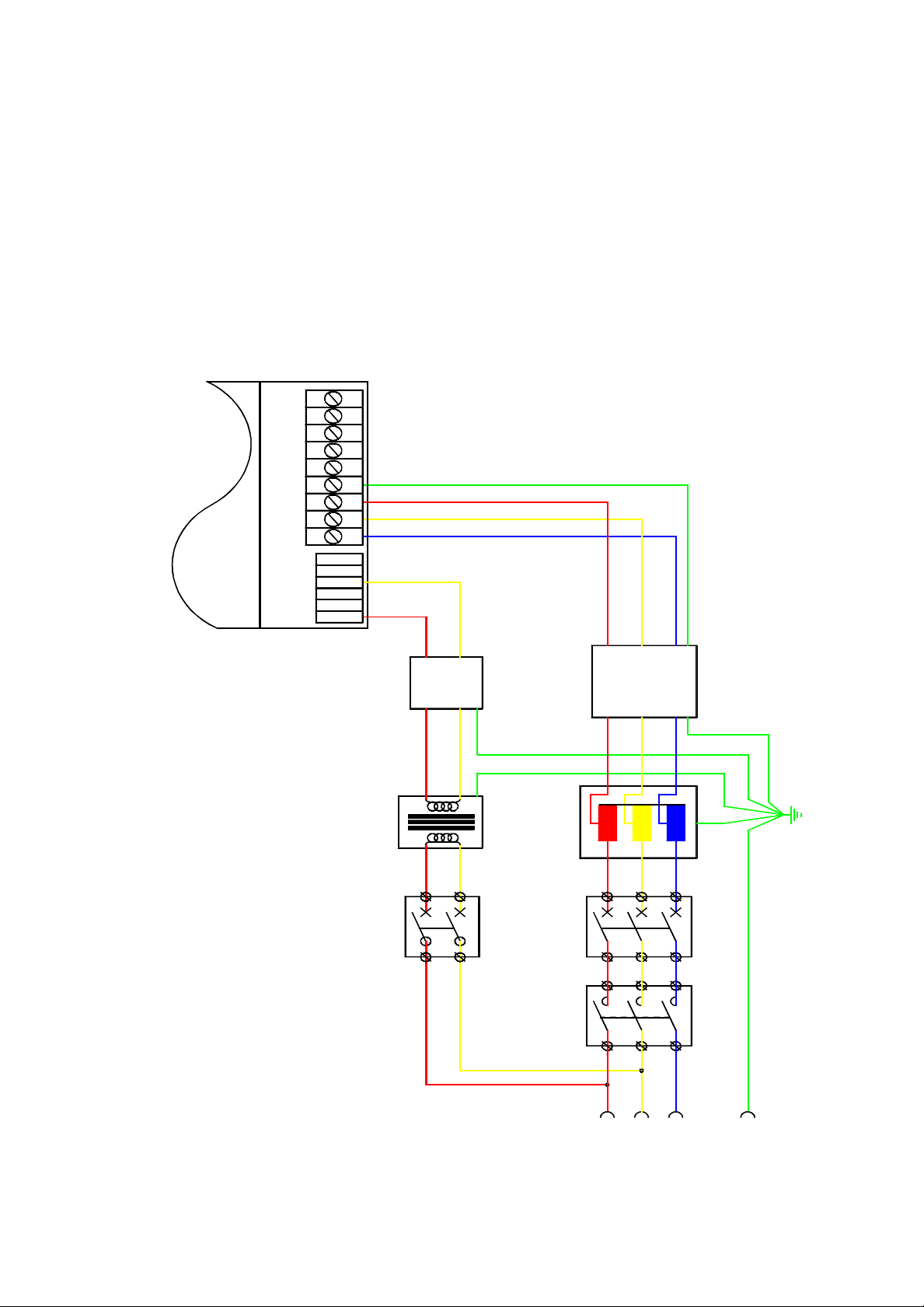
6. Safety - Using Guards and Limits
All machines should include comprehensive safety features. This is essential both for
normal safety considerations, and to comply with H ealth and Safety requirements. It
can also prevent any unwanted interference with the machine while it is running.
All moving machinery must be guarded so that it cannot be reached by anybody while
in motion. The guards should be fitted with guard switches or sensors, connected so as
to immediately cut power from the motors when any gu ard is opened. On some
machines, it may be useful to lock the guards closed by means of a solenoid to prevent
them from being opened while the machine is running. This allows the machine to
detect any attempt to open a guard and shut down the machine cleanly before unlocking
the guard and allowing it to open.
Motors which have constraints or limits on their range of motion should be fitted with
hard wired limit switches. These should cut power from the motors if any motor goes
outside its limits of travel. The machine must also have one or more locking em ergency
stop push-button switches, accessible from several positions around the machine.
Anyone operating or working on the machine must be able to instantly stop the machine
at any time by hitting an emergency stop switch.
There are no limit switches available on the Q-Drive but if the machine require s the use
of limit switches then they may be implemented using the digital i/o functio ns available
on the control system. If the control system is used to provide a limit switch function
then this should be backed up with an mechanical switch which should cut the power
to the Q-Drive.
Guards, emergency stop and limit switches may be connected into the control system
motor control systems, by using the digital input lines. However, the programmable
input functions on the control system should only be used in addition to the
conventional hard wired guard and limit switches, not to replace them. The digital
inputs can be used to trigger a smooth shutdown sequence, or to generate a limit switch
error and shut down immediately. The control system can then remove power from the
motors and drives if required, under software control, by using a digital output line to
switch the motor supply contactors.
switches MUST remove all electrical power fr om the motors and drives,
independently of any action of the control system.
control system, then again all power must be removed from the motors. This is easily
done by connecting the on board relay on each axis controller into the drive enable
function, or into the control circuit for the motor and drive main contactors.
Note that in most cases, it is not necessary to remove power from the control system,
only from all the high power equipment. If power to the control system and encoders
can be maintained even when the motors and drives are shut down, then the system does
not lose any position information. This can allow the machine to start up again much
more quickly than if the control system is powered off as well, since the machine does
not need to execute a complete initialisation before it can be restarted.
In all installations the limit switches and guard
If power is removed from the
Copyright © 1996 Quin Systems Ltd. Page 29
Page 36

Q-Drive Installation Manual Issue 1.5
2
6.1 Choosing a motor
The choice of motor for a particular application depends on several fac tors. Some of
these are given below.
• Maximum torque required.
• Continuous torque required (r.m.s.).
• Maximum motor shaft speed.
• Maximum acceleration rate.
The torque is the turning effort required from the motor in order to accelerate the
mechanical load or system at the desired rate. It is usually measured in Newton metres
(Nm), gram centimetres (gcm), pound feet (lb. ft ) or ounce inches (oz. in) . In order to
calculate the torque required from the motor, it is necessary to find out the following
information about the mechanical system.
• The reflected total inertia of the system or load, at the motor shaft.
• The reflected total friction of the load.
• The internal motor inertia and friction.
• The maximum acceleration rate of the motor.
• Any gear or pulley ratios in the mechanical system.
For example, consider a motor driving a load via a belt a nd pulleys. The total torque
required from the motor is given by:
2
D
1
T
------
ILI
D
+
2
2
D
dθ
M
t
d
1
------
F
+ +=
2
D
2
F
L
M
where T = total motor torque required
D1= diameter of motor pulley
D2= diameter of load pulley
I
= inertia of load
L
I
= inertia of motor
M
d θ
= acceleration at motor shaft
2
t
d
F
= friction torque of load
L
F
= friction of motor.
M
Page 30 Copyright © 1996 Quin Systems Ltd.
Page 37

Issue 1.5 Q-Drive Installation Manual
In most cases, the inertia and friction can be assumed constant, unless the system has a
changing load. In this case the maximum possible load should be used in the
calculations. The required velocity profile of the moto r should be sketched out by
plotting motor velocity against time. The slope of this gives the motor acceleration, and
thus the maximum required acceleration can be found from the steepest slope on the
graph. This acceleration value can then be substituted in the torque equation for a given
motor to see if the motor is powerful enough to do the job.
This can be repeated along the velocity-time plot for al l accelerations to give a graph of
torque against time. This can be used to find the average or r.m.s. continuous torque
required by the system. Servo motors are often specified with both a continuous and a
peak torque rating, and they should be chosen such that the torque requirement of the
machine is well within the capac ity of the motor. Care must al so be taken to ens ure that
the maximum speed of the motor is not exceeded.
Note that if too large a motor is selected, the motor inertia is higher than for a smaller
motor. This affects the maximum acceleration that the motor produces. It is not always
the largest or most powerful motor that accelerates the load at th e quickest rate . Also
note that maximum power transfer from the motor into the load is obtained if the motor
inertia and reflected load inertia are similar.
The ideal motor should have as high a torque to inertia ratio as possible. Pancake o r
printed armature motors are often used beca use they have low rotor inertias. This is also
another advantage of brushless motors, in that they have low rotor inertias because the
rotor often does not have any electrical windings but consists simply of a permanent
magnet on a shaft. Brushless motors also exh ibit better heat dissipation from their
wound stator.
Copyright © 1996 Quin System s Ltd. Page 31
Page 38

Q-Drive Installation Manual Issue 1.5
6.2 Mounting the motor
The motor must be mounted rigidly to the structure of the machine or to a solid floor.
If it is not mounted securely, it may vibrate or oscillate when the motor is powered up
and the position or velocity control loops closed. The motor exerts as much torque on
its mountings as it does on the lo ad. If the mountings are flexible, they ma y form a
resonant syst em, with the motor supplyi ng plenty of power to susta in severe
oscillations.
6.3 Connecting the motor to the load
The motor shaft must be connected se curely to the load. This may be by means of a
drive shaft, a toothed belt and pulleys, or by a gearbox. In all cases the coupling
between the motor and the load must be as stiff as possible, and must have minimum
backlash. At the same time, care must be taken to avo id adding any unnecessary friction
into the system, as this reduces the performance of the servo system.
A common problem when connecting the motor to its load is backlash. This is usually
found in gearboxes, where the input gear is allowed to move by a small amount between
the teeth of the output gear, while the output gear is stationary. A similar effect is seen
if the motor mountings are loose or sloppy, or if the coupling between motor and load
is too flexible. The effect of backlash is not just a loss of position accuracy, but may in
extreme cases result in a highly unstable system. All possible precautions must be taken
to minimise or eliminate backlash in the system.
Page 32 Copyright © 1996 Quin Systems Ltd.
Page 39

Issue 1.5 Q-Drive Installation Manual
7. Drive Parameters
7.1 Serial Link
The serial link is used to set or monitor drive parameters stored in non-volatile memory
using the configuration program.
This program allows the user to:
• set all user adjustable parameters
• monitor inputs and fault status
• In a multi drive configuration it is possible to acce ss all drives from a singl e PC
without having to transfer the serial cable from one drive to another.
With the serial link connected it is possible to monitor the position of the resolver (0-
1024) within one motor revolution.
Hardware:
A personal computer with either an RS422 adapter plus cable or an RS232 serial cable.
The choice depends upon how the drive has been configured.
7.2 Getting Around the Configuration Program
The program QDRIVE.EXE should be installed on an IBM compatible personal
computer (PC) and used to set the drive p arameters and monitor the servo-amplifier
status.
There are 80 parameters available on the Q-Drive that are divided up as detailed below.
On the following pages are descriptions of various parameter and their range of values;
parameters not described should not be changed.
0..10: Motor parameters
11..31: Installation parameters
32..43
44..59: Internal parameters (for testing)
60..63: Parameter protection bits
64..79: Status parameters, read only
Certain parameters only become active after they have been saved with the <F2>
function key. These are denoted by an <F2> symbol in their title
Copyright © 1996 Quin Systems Ltd. Page 33
Page 40

Q-Drive Installation Manual Issue 1.5
Run the configuration program by typing;
QDRIVE <Return>
The initial screen, shown below, appears asking for the password motor to be entered.
The program will allow changes to be made only if the password is correct, but will st ill
run if the password is incorrect to allow parameter monitoring only.
Figure 12. Q-Drive.exe: password entry page
The
QDRIVE.EXE
pr ogram presents the servo parameters using nine pa ges or screens.
The first three pages involve the setup of the servo-amplifier and the absolute position
of the resolver. The last page is used to monitor the inputs and alarm states. Only the
parameters on the first three pages can be modified through the computer program. In
order to change the parameters it is necessary to “Connect” to a pa rticular drive. This
is achieved in the following way.
1 Press the <F8> function key to put the program “On-Line”, the program will
immediately start trying to communicate with drive 1.
2 If drive 1 is not connected then press function key <F4> to scan fo r active
drives, Figure 13. on page 35 shows the program scanning for drives and
finding drive 1. When the active drive has been identified use the procedure
in steps 3 to 5 to connect to it.
3 To change to the required drive press and hold down the <Shift> key and
then press a function key from <F1> to <F10>, this will access drives 1
through to 10.
4 To access drives 11 to 15 press and hold down the <Ctrl> key and then
press a function key from <F1> to <F5>
5 When the desired drive has been selected, the message near the top of the
screen will show “ONLINE Connected”
Page 34 Copyright © 1996 Quin Systems Ltd.
Page 41

Issue 1.5 Q-Drive Installation Manual
Figure 13. Q-Drive.exe: scanning for active drives
Once a drive has been connected to it, it is possible to change the various pa rameters
available on each page. Moving around and selecting the parameters is done using the
following keys:
Change Pages:
The page displayed on the computer is changed by pressing the <TAB> key.
<Shift><Tab> will move backwards through the pages.
Select Parameters
The up/down arrow keys a re used to select the desired parameter on each page. The
selected parameter appears in reverse video, Figure 13. shows Proportional Gain as the
selected parameter.
Change Values:
The plus key <+> and the minus key <-> change the value of the selected parameter
displayed in reverse video. It is also possible to directly enter a value from the
keyboard, simply type in the new value and press the <Return> key.
Save Settings:
The <F2> key saves all settings to non-volatile (EEPROM) memory and in some cases
activates the changed value.
Read File:
A file containing preset drive parameters can be downloaded to the drive using the
<F3> key. Pressing this key will present the default drive parameter file name,
QDRIVE.CFG, this file name can be erased and replaced with another file name.
Copyright © 1996 Quin System s Ltd. Page 35
Page 42

Q-Drive Installation Manual Issue 1.5
Exit Program:
Press <ESC> to exit the program.
New Release:
For more information on new releases please look at the file README.TXT.
7.3 Page 0 Parameters
Figure 14. Q-Drive.exe: page 0 parameters.
0 Proportional Gain: (0..127)
1 Integral Gain: (0..127)
These two parameters determine the proportional and integral gain of the
servo velocity control loop. They are programmable from 0 to 127. Higher
values represent higher gains. The integral gain is cancelled for a value lower
or equal to 3.
2 Speed factor: (-127..+127)
This parameter sets the maximum speed and the direction of rotation of the
motor. This parameter is programmable from -127 to 127 corresponding to a
speed of -6000 rpm to +6000 rpm +/- 10%.
3 Maximum current: (0..127)
This parameter sets the peak current delivered to the motor. This parameter
is programmable from 0 to 127 (127 = maximum peak current of the
amplifier shown in Table 1: on page 9.
Page 36 Copyright © 1996 Quin Systems Ltd.
Page 43

Issue 1.5 Q-Drive Installation Manual
4 Nominal current: (10..64) <F2>
This parameter sets the con tinuous current delivered to the motor. This
parameter is programmable from 10 to 64
5 Pair of motor poles: (1..6)
This parameter sets the number of motor pole pairs for proper commutation.
This parameter is programmable from 1 to 6 (number of motor pole pairs).
6 Phase advance: (0..360)
This parameter is used to optimize the phase advance angle for each type of
motor. At max. speed (speed factor parameter = 127), this parameter can vary
the phase advance angle from 0 to 360 electrical degrees.
This parameter is programmable from 0 to 360° (typical value: 20).
7 Resolver Shift Angle: (-180..+180)
This parameter is used to set the resolver shift angle in software to
accommodate any resolver shift angle set by the motor manufacturer.
This parameter is programmable from -180 to +180 (electrical degrees).
7.4 Page 1 Parameters
Figure 15. Q-Drive.exe: page 1 parameters
8 Motor thermostat normally, open: (0,1)
The servo-amplifier is set to suit the motor thermal switch type by selecting:
0: for motor thermal switch normally CLOSED (or for PTC)
1: for motor thermal switch normally OPEN (or for NTC)
Copyright © 1996 Quin System s Ltd. Page 37
Page 44

Q-Drive Installation Manual Issue 1.5
9 Speed Offset:(-127..+127)
The setting of the servo-amplifier speed offset is done with this parameter.
which is adjustable between -127 and +127.
10 Parameter not used
11 Not used on Qdrive
12 Direction Stop: (0..3)
This parameter is used to prevent the motor from turning in a particular
direction and is setup as follows.
0: Turns in both +ve and -ve directions
1: Only turns in a +ve direction
2: Only turns in a -ve direction
3: Will not turn in either direction
13 Relay, Alarm or Ready: (0,1)
This parameter is used to define the function of the on-board relay:
0: Relay is on when there are no alarms
1: Relay is on when the drive is enabled
14 Inverted display: (0,1)
The 7 segment display can be inverted if the drive is to be mounted upside
down.
1: Normal display
0: Inverted display
15 RS232, RS422 Address: (0..17)
This parameter is used to set the address to which the drive amplifier will
respond and whether the drive is using RS232 or RS422 commu nications.
For use with an RS422 interface the drive can be set to read the address from
the Q-Drive backplane or be set to address 1. For use with an RS232 interface
it can be set to read the address from the Q-Drive backplane or set to an
address in the range 1 to 15:
0: RS422 Read address from backplane
1..15: RS232 Address 1..15
16: RS232 Read address from backplane
17: RS422 Set to address 1
Page 38 Copyright © 1996 Quin Systems Ltd.
Page 45

Issue 1.5 Q-Drive Installation Manual
7.5 Page 2 Parameters
Figure 16. Q-Drive.exe: page 2 parameters
Speed/Resolution: (1,2)
16
<F2>
This parameter selects one of two maximum motor speeds in order to enable
the servo-amplifier for the appropriate encoder resolution range.
The limits are:
1: Max. speed = 3500 rpm Max. resolution = 1024 ppr
2: Max. speed = 6000 rpm Max. resolution = 512 ppr
NOTE.
The encoder simulation will not work if the encoder simulation is set
to 1024ppr and the maximum speed is set 6000rpm
Encoder Resolution: (1..1024)
17
<F2>
This parameter selects the number of pulses generated by the encoder
simulator and can be set anywhere in the range 1 to 1024.
Reference Marker Width: (0..2)
18
<F2>
This parameter selects the width of the simulated encoder marker pulse (Z
pulse) relative to the width of the A channel period. The following values are
available: 1/4 , 1/2 and 1 and are set up as follows
0: 1/4 pulse width
1: 1/2 pulse width
2: 1 pulse width
Reference shift: (-512..+512)
19
<F2>
This parameter is used to shift the simulated encoder reference marker pulse
by +/- 180° relative to the null position of the resolver. It is programmable
over a range of, 512 (-180°) to +512 (+180°).
Copyright © 1996 Quin Systems Ltd. Page 39
Page 46

Q-Drive Installation Manual Issue 1.5
20 Enable: Hard, Trig, Soft: (0..2) <F2>
This parameter defines the way in which the amplifier is enabled. The first
setting, “Hard”, means that the amplifier can only be enabled using the
external contacts availa ble at P12 pins 3and 4. The second setting, “Trig”,
means that the amplifier has to be hardware enabled as in setting 1 above and
then software enabled using the <F5> key. If at any time the ampl ifier
becomes disabled e.g. because of a motor fault then the <F5> key will no
longer work until the hardware enable has been reset, i.e. re moved and then
replaced. The third setting “Soft”, allows the amplifier to be enabled and
disabled using the <F5> key, the hardware enable needs to be set all of the
time for this function to work.
0: Hard
1: Trig
2: Soft
21 Software Watchdog: (0..65535)
The value set in the watchdog parameter determines the time in milli seconds
which the amplifier will wait after the QDRIVE.EXE goes off-line or is
disconnected before reporting error code 9 and disabling the motor. The
watchdog is only active when the drive is enabled. Setting this value to 0 will
disable the watchdog
22 Alarm Latch 2,7,2&7: (0..3) <F2>
This parameters determines how the amplifier treats the Over current (I2t)
and Under voltage alarms, i.e. whether or not they are latched.
0: Neither alarm latched
1: Over current alarm latched
2: Under voltage alarm latched
3: Both alarms latched
23 Optional Speed Module
Page 40 Copyright © 1996 Quin Systems Ltd.
Page 47
Issue 1.5 Q-Drive Installation Manual
7.6 Page 3 parameters
Figure 17. Q-Drive.exe: page 3 parameters
24 to 53: Not used
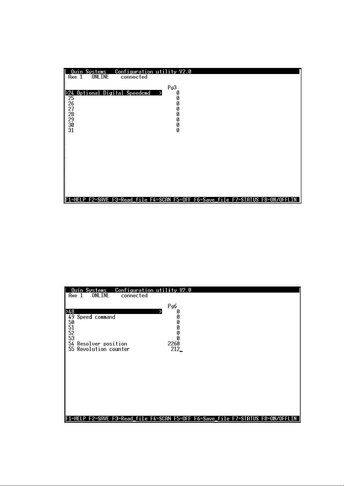
7.7 Page 6 parameters
Figure 18. Q-Drive.exe: page 6 parameters
Copyright © 1996 Quin Systems Ltd. Page 41
Page 48

Q-Drive Installation Manual Issue 1.5
The parameters on Page 6 are Read only and as such cannot be changed.
54 Resolver position
The resolver position is a 12 bit value of the current resolver position within
one rotation.
55 Revolution counter
The revolution counter is a 24 bit count of complete resolver revolutions.
This value can be used with the resolver position to effectively produce an
absolute encoder.
7.8 Page 8 parameters
Figure 19. Q-Drive.exe: page 8 parameters
The parameters on Page 8 are Read only and as such cannot be changed.
Page 42 Copyright © 1996 Quin Systems Ltd.
Page 49

Issue 1.5 Q-Drive Installation Manual
7.9 Page 9 parameters
Figure 20. Q-Drive.exe: page 9 parameters
Max Peak Current (0..127):
74
This parameter defines the maximum peak current that the drive will deliver
to the motor
75 Max Nominal Current (0..127):
This parameter defines the maximum nominal current that the amplifier will
deliver
76 Manufacturing week:
The week number in which the drive amplifier was manufactured.
77 Manufacturing year:
The year in which the drive amplifier was manufactured.
78 Hardware Version:
The hardware version number or revision number of the drive amplifier.
79 Firmware Version:
The firmware or EPROM revision number.
Copyright © 1996 Quin System s Ltd. Page 43
Page 50

Q-Drive Installation Manual Issue 1.5
7.10 Status & Alarm page
Figure 21. Q-Drive.exe: status display
Pressing function key <F7> from any of the nine pages will bring up the status page as
shown above. This page gives a continually updated display of all alarms and the
current status of the drive and is particularly useful whilst commissioning the drive.
Whilst this page is displayed it is possible to change from one drive to another to obtain
the new drive’s current status. If a non existent drive is selected, i.e. drive 6 in a 5 drive
system then the display will continue to show the previous drive’s val ues except for the
top line which will show
“Axe 6 ONLINE no connect”
i Earth Defect:-
If the optional Earth Fault module is fitted and the Q-Drive is supplied from
an Auto-transformer then this alarm indicates a problem with the amplifier
earthing
ii EEPROM Fault
The amplifier has been unable to read data from the EEPROM non-volatile
memory or the data is corrupt
iii Resolver Fault
The resolver or the connections to it are faulty and the system can no longer
read the resolver.
iv RDC Fault
The part of the system designed to convert the resolver signals into digital
signals is faulty.
Page 44 Copyright © 1996 Quin Systems Ltd.
Page 51

Issue 1.5 Q-Drive Installation Manual
v Battery Under voltage
The backup battery voltage is too low to reliably maintain the system in the
event of a power failure.
vi Software Watchdog
Software watchdog has tripped, this usually means that the processor has
stopped running or it is stuck in a perpetual loop.
vii End Switch 1
This alarm cannot occur in the Q-Drive as it does not support end switches.
viii Link Motor Fault
Failure in the wiring from the amplifier to the motor.
ix I2t reached
The amplifier has reached it’s power limit, if the control system is trying to
push the amplifier harder
x Torque Enable Input
This will show ON when the drive is enabled and OFF when the drive is
disabled.
xi Motor Thermostat
The thermostat built into the motor has tripped, the motor should be shut
down and allowed to cool.
xii Heatsink Thermostat
The amplifiers built-in heatsink has overheated, the amplifier should be
switched off and allowed to cool. The optional fans should be fitted into the
Q-Drive enclosure if the fault occurs on a regular basis.
xiii End Switch 2
This alarm can not occur in the Q-Drive as it does not support end switches
xiv Power Fault
The power amp section of the Q-Drive has developed a fault and can no
longer reliably drive the motor.
Copyright © 1996 Quin System s Ltd. Page 45
Page 52

Q-Drive Installation Manual Issue 1.5
This Page is intentionally Left Blank
Page 46 Copyright © 1996 Quin Systems Ltd.
Page 53

Issue 1.5 Q-Drive Installation Manual
8. Switching On
Preparation of AC Brushless servo motors and servo-amplifiers requires a little
more attention than that of DC servo-drives. We recommend that switching on
for the first time is done according to the following instructions.
8.1 Switching the Servo-Amplifier On Without a Motor
The first time the amplifier is switched on the enable contacts (connector P12 pins 3 and
4), should be open circuit. This will disable the power stages of the amplifie r. The
resolver should be connected to the servo-amplifier and some method o f reading the
encoder output, i.e. a Quin PTS system, should also be connected.
The three-motor phases must not be connected to the servo-amplifier.
8.2 Checking LEDS and 7 segment display
LED
“OVER I”
This LED lights up during a short-circuit between two motor phases or a power stage
fault.
The state of the LED and the output stage inhibit are latched. To clear a latched fault it
is necessary to cycle the power. If the power is cycled, ensur e that at least 30 se conds
is allowed between switching off and switching back on. If this delay is shortened then
it is possible that the residual power in the smoothing capacitors will hold up the
amplifier control circuits and the alarm latch will not be cleared.
“Braking”
This LED lights up when the braking modul e operates. This is a non latching alarm and
it is quite normal to see this LED illuminate particularly under fast braking conditions
with a heavy load.
red LED normally off
yellow LED normally off
Copyright © 1996 Quin Systems Ltd. Page 47
Page 54

Q-Drive Installation Manual Issue 1.5
8.3 7 segment display on the front panel
This display shows the state of the servo-amplifier and motor. The alarm d has the
highest priority (following C, 7, 6, 5 etc.). If some alarms take place simultaneously,
only the one with the higher priority will be displayed. A alarm reset is only possible
by switching off the servo-amplifier supply.
Servo-amplifier powered on
and enable contact closed
Servo-amplifier powered on, enable
contact closed and motor at zero position
Servo-amplifier powered on
and enable contact open
Servo-amplifier powered on, enable
contact open and motor at zero position
Continuous current limit reached
Motor over temperature fault (alarm latched)
Amplifier heatsink over temperature fault.
Alarm latched
Resolver digital converter not functioning.
Alarm latched
Resolver feedback fault.
Alarm latched
Power amplifier section faulty.
Decimal point displayed with any other
display to show clockwise motor rotation.
Motor connection failure
Ground fault detected.
only if option fitted
Figure 22. Seven segment display codes
Page 48 Copyright © 1996 Quin Systems Ltd.
Page 55

Issue 1.5 Q-Drive Installation Manual
8.3.1 Checking the electrical rotation sense of the resolver
The decimal point of the 7 segment display lights up when the motor shaft is turned
clockwise.
Figure 23. Electrical rotation sense of the resolver
If the decimal point lights up during anti-clockwise rotation, connections to the upper
half of connector P2 pin 7 (COS1) and pin 6 (COS2) must be reversed.
Copyright © 1996 Quin System s Ltd. Page 49
Page 56

Q-Drive Installation Manual Issue 1.5
8.4 Determining the motor phases
This operation must only be done when the three-phase motor order is unknown (motor
prototype or no documentation).
It is necessary to have a DC supply of about 3A. and of sufficient voltage to move the
motor but not in excess of the motor rated voltage.
The procedure is as follows:
1 Define arbitrarily the Phase U as one of the 3 motor phases.
2 Connect U to
“+”
and a
2nd phase
motor to
“-”
of the DC supply.
3 Switch supply on. The shaft will move to a stable position.
4 Mark the new shaft position with a pencil, at top dead centre.
5 Disconnect the “-” of the supply from the
6 connect the “-” to the
3rd phase
motor. Observe the axis rotation direction.
2nd phase
of the motor and
7 Mark with a pencil the new shaft axis position.
With the help of the table below, determine the 2 unknown motor phases.
sense of axis rotation 2nd phase 3rd phase
clockwise
anti-clockwise
V W
W V
Table 9: Motor Phase Determination
Page 50 Copyright © 1996 Quin Systems Ltd.
Page 57

Issue 1.5 Q-Drive Installation Manual
8.5 Switch the Servo Amplifier on with a Motor and
Optimization
8.5.1 Preparation before switching the mains voltage on
a) Disconnect motor from the machine.
The 3 phases motor should be again connected to the servo-amplifier. Check
if the axis is stopped and release the motor brake.
b) Check the following connections:
• motor cable to the backplane
• resolver cable is plugged into P2 (Upper)
• control signals connected to P10 pins 3 and 4, +ve to pin 3, 0v to pin 4.
• enable contact connected to P12 pins 3 and 4.
c) Reduce the maximum current setting of the servo-amplifier us ing the Q-
DRIVE software. Save this value using the key
< F2 >
.
d) Set the proportional and integral gains to 25 and 10 respectively. Also set t he
resolver shift angle to 90 degrees. Save these values using
the < F2 > key
e) Open the enable contact connected on P12 pins 3and 4.
8.5.2 Switching the mains voltage on
a) Switch on the amplifier.
b) The 7 segment display should indicate “1”.
c) Set a positive speed voltage (about 1 V) to the servo-amplifier and close the
enable contact. The 7 segment display should now show “0”.
d) Increase the
max. current
parameter until the motor starts running.
If the motor doesn't turn or turns very slowly, check the sta te of the motor
brake if fitted.
e) Reverse the polarity of the speed command and check that the motor turns in
the reverse direction.
.
f) Set the
Save the
Copyright © 1996 Quin System s Ltd. Page 51
max. current
max. current
parameter to the initial state.
using the key <F2>.
Page 58

Q-Drive Installation Manual Issue 1.5
8.6 Compensating the speed controller
Optimizing the performance of the motor over the whole speed range can be achieved
by adjusting the drive amplifiers
Proportional Gain
Connect a Personal computer to the amplifier and run the QDRIVE.EXE configuration
program:
a) Set the value of both proportional (KP) and integral (KI) gain to a value of
10, this represents a very low gain setting.
b) Connect an oscilloscope between measuring points on J1, pins 9 and 10, pin
9 is signal and pin 10 is ground.
c) Switch on the servo-amplifier and close the enable contact.
d) Apply a low command speed voltage (<100 m V)
Integral Gain
and
parameters.
e) Increase the valu e of the
Integral Gain
parameter whilst ensuring that the
following factors are maintained:
i good static torque
i smooth shaft rotation
f) Apply a step function of 2 v olts to the command input and monitor the
response of the drive using an oscilloscope. One of the three following results
will occur:
i The signal shows several oscillations, this means the system is under
damped, in this case increase the
Proportional Gain
value
ii The motor is noisy, this means that the motor is over damped, in which
case decrease the
Proportional Gain
value
iii The signal shows only one small overshoot, this indicates critical
damping has been achieved and therefore the speed loop overshoot is
optimized
g) When the
f iii)
condition is achieved, save the gains obtained with key <F2>.
8.6.1 Offset and speed compensation Offset compensation
a)
The setting of the servo-amplifier speed offset is done with the
offset control
parameter in the QDRIVE.EXE software.
The setting of the offset can be done with or without the position controller.
If a position controller, such a Quin PTS unit, is used then all of the controller
gain parameters must be set to zero. Having set the controller gain parameters
to zero enable the controller output and adjust the servo-amplifier offset
compensation value until the motor stops moving. There will probably be a
range of values where the motor appears to be stationary, find the limits of
this range and set the value to the mid point. To set the offset value without a
controller attached then short out the command input terminals and adjust the
offset value. Again there will probably be a range of values which result in
Page 52 Copyright © 1996 Quin Systems Ltd.
Page 59

Issue 1.5 Q-Drive Installation Manual
the motor remaining stationary, find the limits of the range and set the value
to the mid point.
Press the < F2 > key to save this value.
b) Speed compensation
The Speed factor parameter allows adjustmen t of the motor speed from 6000 rpm to + 6000 rpm.
Press the <F2> key to save this value.
Copyright © 1996 Quin Systems Ltd. Page 53
Page 60

Q-Drive Installation Manual Issue 1.5
8.7 Trouble Shooting
The following table shows the most frequent troubles and their causes.
No Trouble Possible cause
1 LED “OVER I”
switched on
2 Display 2 limit of continuous current reached
3 Display 3 motor overloaded
4 Display 4 servo-amplifier overloaded
5 Display 5 resolver conversion circuit failure
6 Display 6 resolver failure - resolver wiring failure
7 Display 7 appears with OVER I LED
8 Display C motor connection failure
9 Display d detection of a motor ground defect (option) with
10 Motor doesn't turn. Display
shows 0 when speed
command is applied
short-circuit between 2 motor terminals
Resolver Shift Angle
-
- badly wired or loose connection of wires for motor
thermal switch
- cooling fan failure
Resolver Shift Angle
-
- brake fuse failure or missing
- appears in case of over-voltage or supply missing
auto-transformer
- max. current of servo-amplifier limited too low
- motor brake engaged
- speed reference short-circuited by
parameter incorrect
parameter incorrect
REF
Jumper
11 Motor rotation is not smooth
12 Motor turns in wrong
direction
Table 10: Q-Drive Trouble Shooting
Motor pole pairs
- Motor wiring on terminal U, V, W not in the correct
sequence
Command signal is wired incorrectly, Reverse
connections to PP10.3 and P10.4 and change the
setting of jumper J3.
parameter incorrect
Page 54 Copyright © 1996 Quin Systems Ltd.
Page 61

Issue 1.5 Q-Drive Installation Manual
9. Testing the System
9.1 General
This section describes some si mple test procedures for some parts of the Q-Driv e
systems. These do not comprise a full system test, but may be useful to verify the basic
operation of the system, the motor and the encoder.
All these tests require the use of a personal computer w ith a serial port, preferably
RS422. Most test can be carried out on the PC but additional test equipment may be
necessary. The test are given in a logical sequence i.e . it is not possible to check the
resolver interface if the Serial communications do not work and the encoder simulator
will not generate signals until the resolver interface works.
9.2 Serial port
The serial port only transmits data after it receives a request from the QDRIVE.EXE
software, this means that it is necessary to connect a personal computer (PC) and run
the QDRIVE.EXE software in order to test the serial port. Ensure that the program is
requesting data from the axis number which the drive is set to, i.e. if the drive is set to
address 7 then the program should request data from axis 7. If the serial
communications are working correctly then the program will display the line:
“Axe 7 ONLINE”
Press the <F2> key this should make the 7 segment display on the front of the drive
flash. If there is no response from the drive then check the connections between the PC
and the drive. If there is still no response from the drive then check the serial data
signals using a data analyser or an oscilloscope, to verify whether the drive is actually
responding to the characters being sent to it. The serial data analyser should be set for
9600 Baud, 8 data bits, no parity and 1 stop bit.
9.3 Resolver Interface
Connect a resolver to the drive and monitor the
6 of the
produce an updating display every time the resolver shaft is moved then the drive will
need to be returned to Quin Systems Ltd. for repair.
QDRIVE.EXE
program whilst turning the shaft of the resolver. If this does not
“Resolver Position”
read out on page
Copyright © 1996 Quin System s Ltd. Page 55
Page 62

Q-Drive Installation Manual Issue 1.5
9.4 Encoder Simulator
The operation of the encoder simulator can be checked using a control system such as
a Quin Systems PTS unit. Connect the encoder output of the drive to the encoder input
on a PTS system and switch on both the drive and PTS system. Using a terminal
connected to the PTS type the command “DM” and then turn the shaft of the motor.
Whilst monitoring the second column of data turn the shaft in one direction, this should
produce positional data climbing in a positive or negative direction, turning the shaft in
the opposite direction should take the data back to zero and then climbing in the
opposite direction.
If the encoder position counts up and down by only one count, then one of the two
phases of the encoder signals is not being detected. If the encoder position value does
not change at all, then either or both phase signals are missing. If the position tends to
count either up or down whichever direction the shaft is turned, then the track A and B
signals are mixed up with their complementary signals, such that instead of the system
receiving two signals in quadrature, it always receives two signals in opposite phase
regardless of the shaft direction. These problems can be confirmed by monitoring the
encoder signals with an oscilloscope.
Page 56 Copyright © 1996 Quin Systems Ltd.
Page 63

Issue 1.5 Q-Drive Installation Manual
4400 K
10. Configurations
10.1 General
This section gives details of the configuration options on all the drive boards used in the
Q-Drive range of servo amplifiers, although the settings are not normally changed. The
amplifiers are set up as described below when shipped.
10.2 Resolver Ratio
The ratio and the amplitude to the primary of the resolver are determined by resistors
RSIN, RCOS and RREF.
Standard fitting:
RSIN = RCOS = 0 (bridge) for a resolver ratio of 2:1
RREF = 12 k ohm to obtain 4V
Special cases:
Use the following formula:
Where: - RREF is expressed in k ohm
to the resolver primary
eff
88
=
---------- Vref
10–
Rref
where: -Vref is rms voltage applied to the primary of the resolver.
Vref max. = 6 V
To calculate the values of Rsin and Rcos use the following formula, where Rcos and
Rsin are expressed in k ohm
Rsin Rcos
Kr is the resolver ratio
(Resolver ratio 2 : 1 corresponds to Kr = 0,5)
-----------------------10 Vref–
r×
100–==
Copyright © 1996 Quin Systems Ltd. Page 57
Page 64

Q-Drive Installation Manual Issue 1.5
10.3 Amplifier Configuration
The location of the solder bridges and jumper links used for configuration and the fuse
locations is given in Figure 26. on page 64 .
Name Element Function
SAD Solder bridge
VITCRT Solder bridge
BD1
BD2
BD3
BD4
BDOUT
INCABS Solder bridge
Solder bridge RS 232 serial link baud rate:
Solder bridge Synchronous link (option):
Table 11: Amplifier Configuration
1-2
: analogue command voltage (default)
2-3
: numeric command vo lta ge th r ough RS 232 se rial
link or through synchronous link (option)
1-2
: speed regulation (standard)
2-3
: current regulation
only BD2 soldered: 9600 Bd (default)
only BD1 soldered: 19200 Bd
only BD3 and BDOUT soldered: internal clock at
38400 Hz
only BD4 soldered: external clock
2-3
: encoder simulation available at the encoder
output connector (default)
1-2
: absolute position available th rough the se rial link
(option)
10.4 Servo-amplifier fuses
The following fuses are factory fitted on all Q-Dri ve units, the loca tion of the fuses can
be found in Figure 26. on page 64
Servo-amplifier type QDV-1-6 QDV-1-10
DC-BUS 10 AT 15 AT 20 AT
Braking module 4 AF 5 AF 8 AF
Supply 1 AT 1 AT 1 AT
Table 12: Amplifier Fuses
QDV-1-18
DC-BUS Fuse (F1)
“Littlefuse 326" are used on the DC-BUS. Dimensions: 6,3 x 32 mm.
Braking module fuse (FFR)
For units type QDV-1-6, “Wickmann 19194" type fuses are used.
Dimensions: 5 x 20 mm.
Page 58 Copyright © 1996 Quin Systems Ltd.
Page 65

Issue 1.5 Q-Drive Installation Manual
For unit types QDV-1-10 and -18, “Littlefuse 314" type fuses are used.
Dimensions: 6,3 x 32 mm.
Supply fuse(FHT)
All QDV-1 drives use a 20mm fuse
Warning:
Blown fuses should only be replaced with the same type and rating fuse and only after
the fault has been corrected. This work should be undertaken by qualified personnel.
Copyright © 1996 Quin System s Ltd. Page 59
Page 66

Q-Drive Installation Manual Issue 1.5
10.5 Backplane configuration
The various jumpers available on the Q-drive backplane are detailed in Table 13:
below. Figure 24. on page 61 shows the jumpers in their default positions
Name Jumper Function
Test points J1
“Valid” bypass &
RS422
terminators
Ground
reference
Address
range
Tx
inversion
Rx
inversion
J2
J3
J4
J5
J6
1
: Not used
3
: Not used
5
: ISMO
7
: COMO
9
: VEMO
2, 4, 6, 8 & 10
1-2
: By-pass “Valid” opto isolator.(Default)
3-4
: 0V connection when “Valid” is by-passed.(Default)
5-6
: RS422 transmit terminator.(Default)
7-8
: RS422 receive terminator.(Default)
1-2
: “S-” differential input connected to 0V (P10-4)
(Default)
2-3
: “S+” differential input connected to 0V(P10-3)
1-2
: Address range 1 to 15 (Default)
2-3
: Address range 16 to 31
1-3 & 2-4
1-2 & 3-4
1-3 & 2-4
1-2 & 3-4
Table 13: Backplane configuration Jumpers
: Gnd connection
: Tx and /Tx non-inverted (Default)
: Tx & /Tx inverted
: Rx and /Rx non-inverted (Default)
: Rx & /Rx inverted
Page 60 Copyright © 1996 Quin Systems Ltd.
Page 67

Issue 1.5 Q-Drive Installation Manual
SW1
0
1
F
2
E
D
C
B
A
7
9
8
P12
J4 J3 J2
3
4
5
6
11
P11
P10
J1
1
1
RESOLVER
ENCODER
P4
RS422/232
J6 J5
P2 Upper
P2 Lower
P3
RS422
Figure 24. Backplane configuration
Copyright © 1996 Quin System s Ltd. Page 61
Page 68

Q-Drive Installation Manual Issue 1.5
10.6 Backplane Fuse
The backplane is fitted with a single fuse rated at 500mA fast blow. This fuse is used
to protect the auxiliary supply when this option is fitted. It is accessed by removing the
front panel and extracting the drive amplifier card, the fuse can then be seen in the lower
left hand corner as shown in Figure 25. below.
IMPORTANT: Ensure that the auxiliary power is removed from the drive before
attempting to replace this fuse.
FUSE F1
Connector
for optional
fans
R'
S'
R'
P7
S'
Fan
Fan
SUPPLY
T S R
Figure 25. Backplane fuse
P8
EARTH
P9
MOTOR
W V U
Page 62 Copyright © 1996 Quin Systems Ltd.
Page 69

Issue 1.5 Q-Drive Installation Manual
11. Options List
Absolute position
The resolver and associated circuits can be permanently powered by an external +/12V battery supply. This option is wired onto the Q-Drive backplane using connectors
P11 and P12
Ground Defect
With this option it is possible to detect a ground defect in the supply but will only work
with an auto-transformer
220V Auxiliary Supply
An auxiliary supply can be wired into the drive using the connections marked R’ and
S’. This auxiliary supply is used to maintain the power to the low voltage part of the
drive so that positional info rmati on will not be lost i n the eve nt that the main c ontactor
drops out, it will not supply power to the amplifier part of the drive. It is vitally
important that the phase wired to R’ is the same phase that is wired to R and similarly
that the phase wired to S’ is the same phase that is wired to S. A typical connection
diagram is shown in chapter 3
.
Multi-Modules
Option 4 RDC modules. Each module define a maximum speed motor for a command
of +/- 10V.Ex: 6000 rpm - 3000 rpm - 1500 rpm - 700 rpm
Copyright © 1996 Quin System s Ltd. Page 63
Page 70

Q-Drive Installation Manual Issue 1.5
Layout of Drive Amplifier
FFR
BO4
BO3
BO2
BO1
SAD
F1
FHT
TRI
SAD
IMAX
VITCRT
INCABS
MO01
RCOS
RSIN
RREF
Figure 26. Drive amplifier jumper & fuse locations
Page 64 Copyright © 1996 Quin Systems Ltd.
Page 71

Issue 1.5 Q-Drive Installation Manual
to Connect
Use P3 or P4
to PC COM port
Screened Resolver cable
Screened Motor Cable
P3
RS422
P2 Upper
P2 Lower
P4
ENCODER
RESOLVER
P10
P11
P12
SW1
RS422/232
Screened Encoder cable
Interface
Diagnostic
Connect to PC COM
port or dumb terminal
PTS Control System
transformer
1ø isolating
p
m
MCB
2ø 3 A
Filter
1ø 3A
uto3ø A
transformer
p
m
MCB
3ø 16 A
ø2
ø1
Filter
3ø 16A
ø3
E
Figure 27. Complete wiring plan
Copyright © 1996 Quin System s Ltd. Page 65
Page 72

Q-Drive Installation Manual Issue 1.5
This Page is intentionally Left Blank
Page 66 Copyright © 1996 Quin Systems Ltd.
Page 73

Issue 1.5 Q-Drive Installation Manual
Index
A
acceleration 31
alarm
battery undervoltage 45
earth defect 44
EEPROM fault 44
endswitch 45
heatsink thermostat 45
I2t current limit 45
link motor 45
motor thermostat 45
power fault 45
RDC fault 44
resolver fault 44
software watchdog 45
torque enable 45
alarm latch 40
analogue readings 9
average torque 31
B
backlash 32
braking 47
C
cable lengths 14
characteristics 2
choice of motor 30
choosing a motor 30
configuration program 33
connections
earth 26
mains supply 24
motor and drive 27, 28
connectors
aux supply 21
earth 20
encoder 16
motor 20
resolver 15
RS232/RS422 18
signals 19
three phase 20
cooling 7
couplings 32
D
DC brushless 1
depth 7
direction stop 38
directives 11
display 38
drive connections 27, 28
drive parameters 33
drive performance 9
E
earth connections 26
electrical installation 23
EMC Directive 11
emergency stop 29
encoder
cables 16
faults 56
testing 56
encoder resolution 39
F
fixing centres 10
friction 31
function key
F2 33
F4 34
F7 44
G
guards 29
H
height 7
humidity 7
I
inertia 31
installation
earth connections 26
mains supply 24
integral gain (KI) 36
introduction 1
Copyright © 1996 Quin Systems Ltd. Page 67
Page 74

Q-Drive Installation Manual Issue 1.5
L
LED’s 47
M
machine guards 29
Machinery Directive 11
mains supply installation 24
maintaining position information 29
max nominal current 43
max peak current 43
maximum current 36
motor connections 27, 28
motor inertia 31
motor installation 32
motor phases 50
motor selection 30
motor thermostat 37
mounting details 10
mounting the motor 32
N
nominal current 37
O
offset compensation 52
over current 47
P
pair of motor poles 37
parameters
page 0 36
page 1 37
page 2 39
page 3 41
page 6 41
page 8 42
page 9 43
status and alarm page 44
phase advance 37
power down 29
proportional gain (KP) 36
Q
QDRIVE.EXE
online 34
password 34
R
r.m.s. torque 31
read file 35
reference marker width 39
reference shift 39
relay function 38
resolver
rotational sense 49
resolver position 42
resolver shift angle 37
revolution counter 42
RS422 address 38
S
safety
guards 29
limit switches 29
save settings 35
serial link 33
seven segment display 48
shutdown 29
software watchdog 40
specification 9
electrical 8
environmental 7
mechanical 7
power supply 7
speed compensation 52
speed factor 36
speed module 40
speed offset 38
speed/resolution 39
system tests 55
T
temperature range 7
testing
encoder 56
general 55
serial port 55
testing the encoder 56
torque 30
torque calculation 30
trouble shooting 54
V
velocity profile 31
Page 68 Copyright © 1996 Quin Systems Ltd.
Page 75

Issue 1.5 Q-Drive Installation Manual
W
weight 7
width 7
wiring faults 56
Copyright © 1996 Quin Systems Ltd. Page 69
 Loading...