

Page 1
INSTRUCTION MANUAL
NT.1310 & QG.1410 Series
for Installing
FURNITURE BARN DOOR HARDWARE
Page 2
Instruction Manual for Installing Furniture Barn Door Hardware
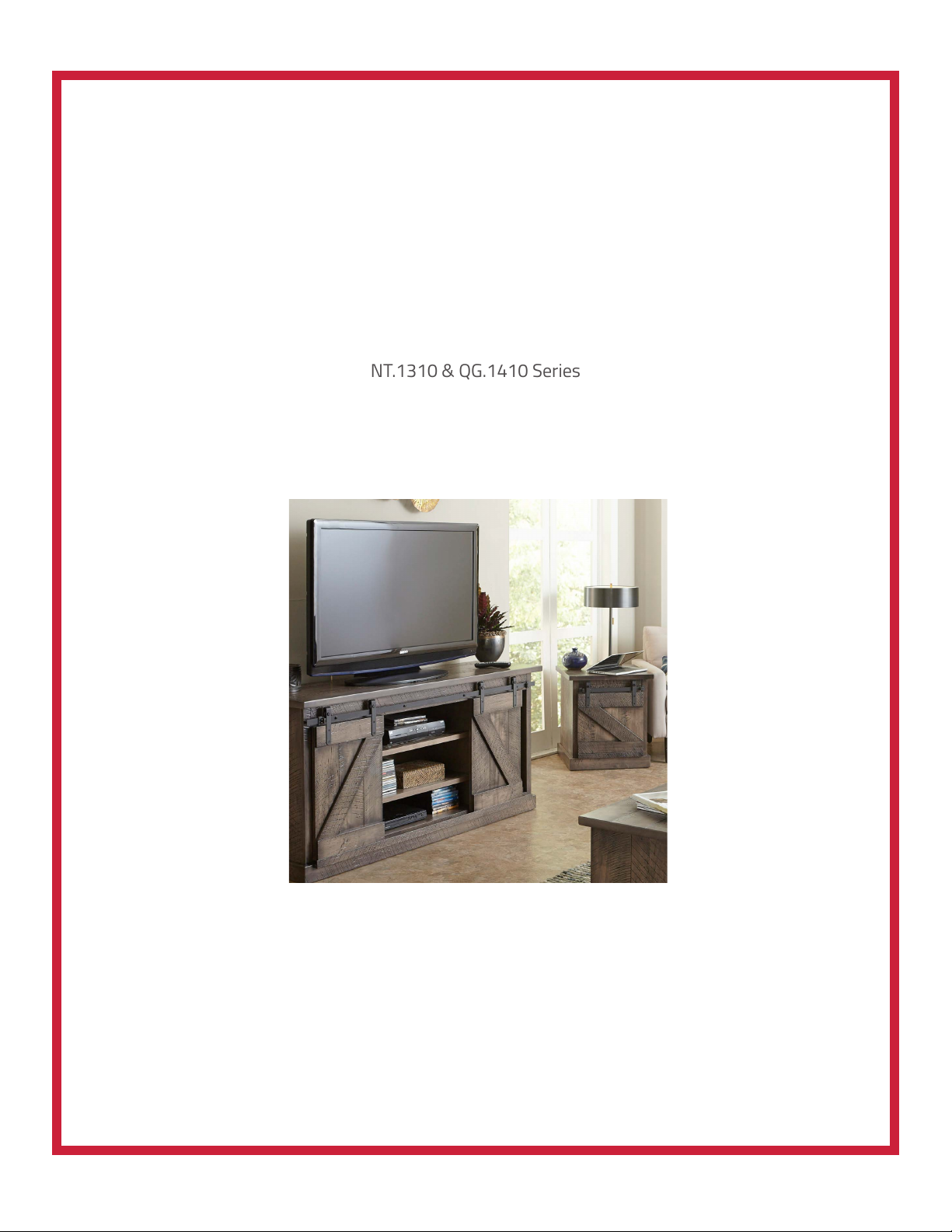
Shown: QG.1410.01.08
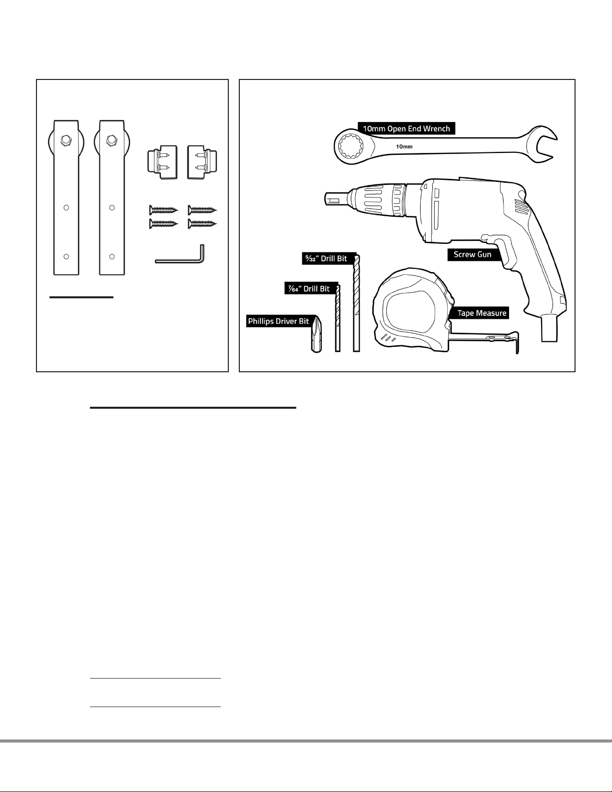
Comes with:
Two (2) Hook Carriers
Two (2) Door Stops
Four (4) Screws
2mm Allen Wrench
Installation Tools Needed:
Step 1: Installing the Straps on the Door (see figure 1)
1. For a single door installation, center the strap on the stile of the door or space it a
minimum of ⅝” from the edge of the door.
Note: For a biparting door application using the supplied adjustable door stops in the middle, there must
be a minimum of a ⅝” gap between the edge of the door and the edge of the strap for the doors to close
together properly.
2. Locate the top fastening hole by measuring from the top of the door down 1”. Mark the
location on the door.
3. Locate the bottom fastening hole by measuring from the top of the door down 3”. Mark
the location on the door.
Note: when using the optional anti-jump discs, part number NT.1318.08, the fastening hole
measurements will be ⅞” and 2 ⅞” respectively. The anti-jump discs CANNOT be used with the optional
soft-close mechanism.
4. Place the strap on the door and align the holes with the center marks on the door.
5. Using a #5 Vix bit or a ⁄ ” drill bit, drill a pilot hole.
6. Fasten the straps to the door with the supplied #6 x ¾” Phillips-drive pan-head screws.
Maximum door thickness = 1 ⅛” (when using the standard 1” standoff that is supplied
with each rail kit, NT.1302 series)
Maximum door thickness = 1 ½” (when using the optional 1 5/16” standoff, part number
NT.1303-34mm.08, sold separately)
2
Page 3
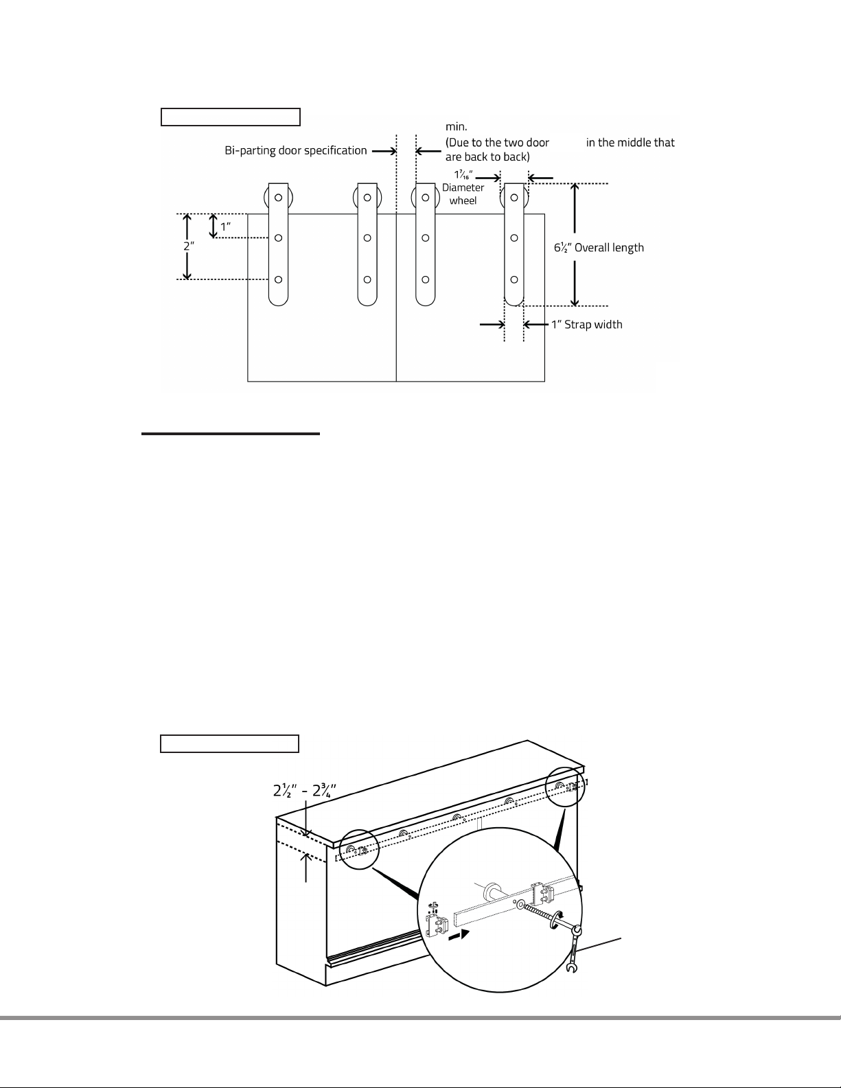
Figure 1
Top of door to
center of hole
⅝”
stops
Step 2: Installing the Rail (see figure 2)
1. Locate the desired position of the rail on the furniture/cabinet piece.
Note: In applications where the rail will be installed beneath an overhanging table/countertop, allow a
minimum of 2 ½” – 2 ¾” from the center of the rail to the underside of the table/countertop. This will create
approximately ¼” of clearance between the top of the strap and the underside of the table/countertop.
2. Draw a line on the face frame where the center of the rail will be installed.
3. Locate the fastener locations for the rail on the line (see attached “Specification for
Furniture Barn Door Rails and Standoffs” on p. 10 for center-to-center hole locations).
4. Drill a ⁄” (4mm) pilot hole into the face frame for each fastener hole location.
5. Using the supplied lag screws, fasten the rails to the face frame, using a 10mm socket
drive or 10mm open end wrench.
SPECIAL NOTE: In biparting door applications where doorstops are used in the center
between the 2 doors, be sure to mount these on the rail and slide them into the approximate
position before installing the rail onto the face frame.
Figure 2
10mm open end
wrench or socket
3
Page 4
Step 3: Securing the bottom of the Doors (from moving in and out)
There are a variety of ways that to accomplish this. Below are two possible methods.
1. Channel method (see figure 3)
a) Within the furniture piece or cabinet design, incorporate a bottom channel the
door will ride in. This channel should be slightly wider than the door and deep enough to
firmly keep the door in place.
b) Add one strip of felt or vinyl to the back of the door that sits in the channel
and another piece to the inside front of the channel. This will allow the door to run
smoothly within the channel.
Figure 3
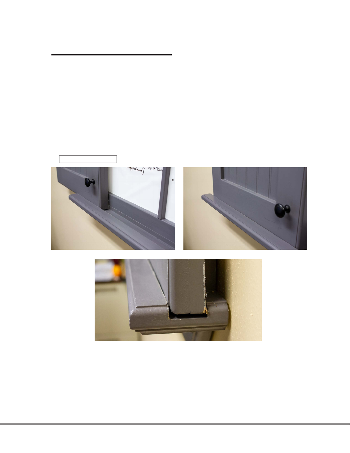
2. Door guide bolt method (part number HA.404.19.11B) (see figure 4a)
(This method involves using the door guide bolt along with a groove cut in the skirting trim of the furniture/
cabinet located below the door)
a) Drill a 35mm hole centered in the back of the door. The center of the 35mm
hole should be ½” up from the bottom edge of the door and drilled to a depth of ½”.
b) Install the door guide bolt into a 35mm hole in the back of the door. Secure the
door guide bolt to the door using pressure fit, glue, or screws.
4
Page 5
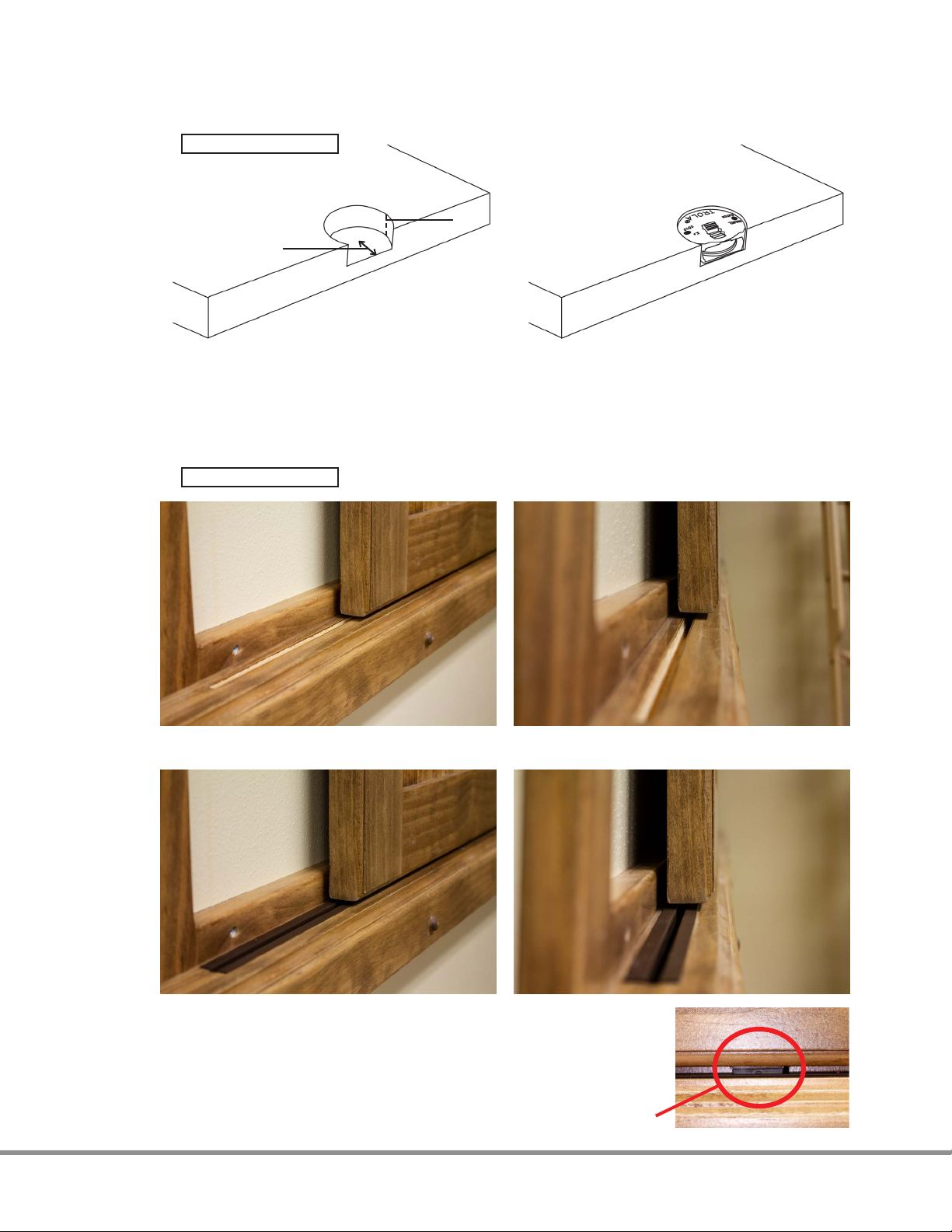
Figure 4a
1/2”
1/2”
c) Make sure the groove in the skirting trim of the furniture/cabinet is ¼” wide
and ½” deep. This groove should be directly in line with the “fin” of the door guide bolt.
Note: For a smoother glide of the door in this groove, insert the plastic channel (part number
QG.1313.CH36.07 or QG.1313.CH48.07), into the groove (see figure 4b).
Figure 4b
Without plastic channel
With plastic channel
Door guide bolt
5
Page 6
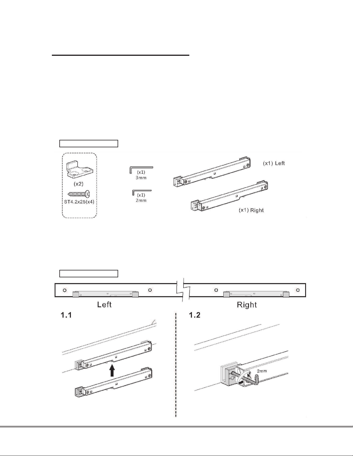
OPTIONAL: Soft-Close Mechanism Installation
Although the soft-close mechanism can be installed after the rail has been mounted, it is
much easier to access the small set screws that secure the mechanism to the rail prior to
mounting the rail.
For the soft-close mechanism to operate correctly, the gap between the top of the door
and the bottom of the rail must be ¼”.
1. The soft-close mechanisms come as a pair, left and right, so be sure to install the
mechanism in the correct orientation (see figure 5a).
Figure 5a
2. Determine the location of the soft-close mechanism on the rail (approximately above
the middle of the door where the door will be in the stopped position).
3. Using the supplied 2mm Allen wrench, secure the mechanism onto the rail by
tightening all four set screws (figure 5b).
Figure 5b
6
Page 7
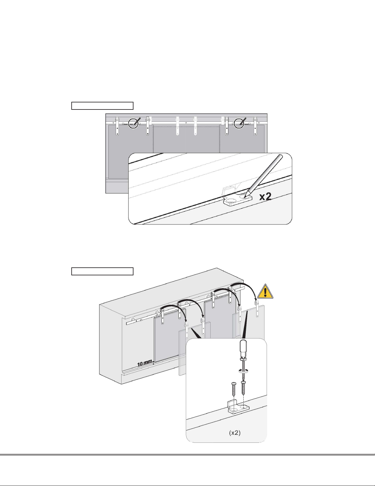
4. With the rail installed on the furniture/cabinet and the door installed on the rail, move
the door to the desired closed position (where the soft closure will slowly bring the door
into this position).
5. Position the soft-close actuator on the top of the door so that the tip of the actuator
rests in the captured position in the soft-close mechanism (figure 5c).
Figure 5c
6. Mark the location of the actuator on the top of the door, then remove the door and
install the actuator on the door by predrilling the mounting holes and using the supplied
screws (figure 5d).
Figure 5d
7
Page 8
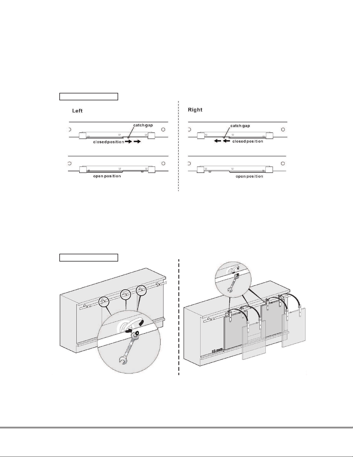
7. Reinstall the door (figure 5f). With the soft-close mechanism in the “loaded” position,
move the door until the actuator meets the soft-closure. Verify that the actuator is
in the correct position on the door so that the actuator fully engages the soft-close
mechanism (figure 5e).
Figure 5e
8. Push the door until the soft-closer “grabs” the door and softly closes it. Adjust the
position of the actuator, if necessary, to soft-close the door.
Note: It is also critical that the actuator is positioned in such a way that, when opening the door, the soft-close
mechanism returns and stops in the “loaded” position, ready to engage with the actuator when the door is to
be soft-closed again.
Figure 5f
Loosen the rail screws near the soft-close
mechanisms to make it easier to reinstall
the door.
Install the door on the rail and re-tighten
the screws.
8
Page 9

Specifications for
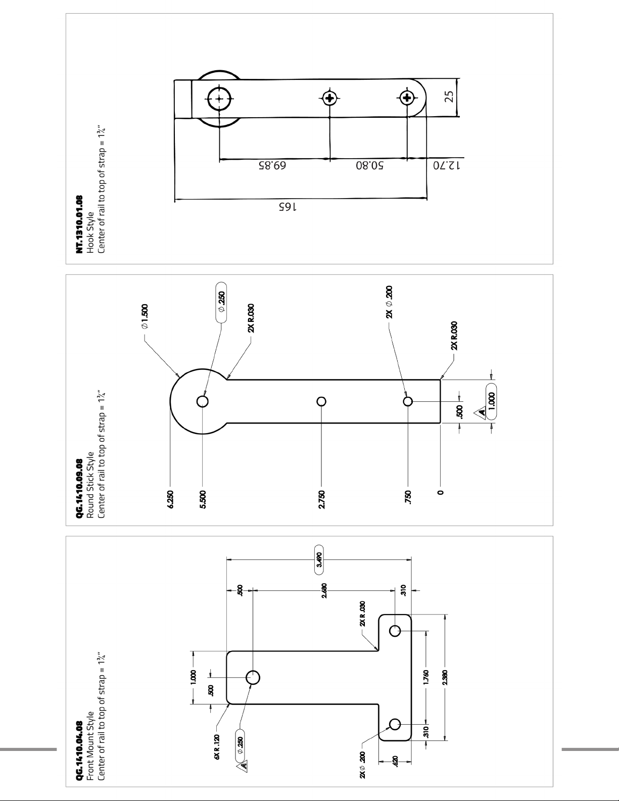
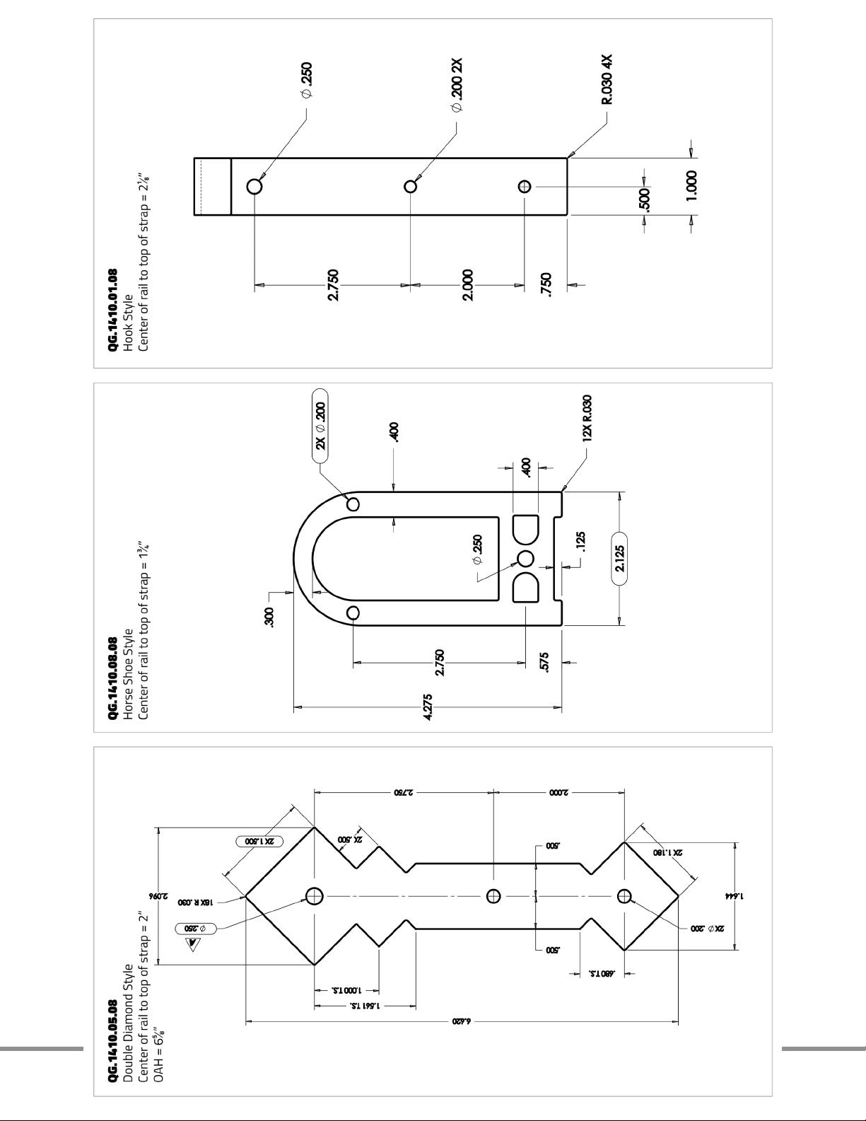
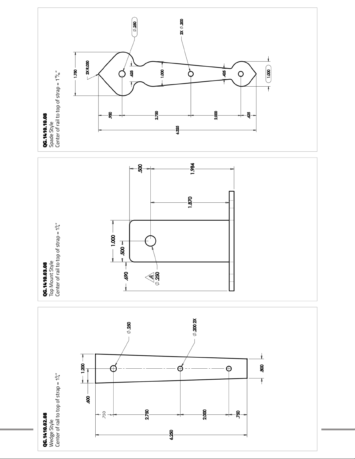
Furniture Barn Door Hardware Straps
Helpful design/installation specifications:
When using the standard 1” long rail standoffs
(included in rail kit)
1¼” = Distance between the front face of furniture/cabinet to the back of the strap
(installed on the rail)
1¼” minus door thickness = gap between furniture/cabinet face and back of door
(example: 1⅛” thick door would have a gap of ⅛”)
Lag Screw length = 2”
Lag screw will penetrate into the wood header by ⁄”
Maximum door thickness = 1⅛”
When using the optional ⁄” long rail standoffs
(sold individually, NOT in rail kits)
1⅝” = Distance between the front face of furniture/cabinet to the back of the strap
(installed on the rail)
1⅝” minus door thickness = gap between furniture/cabinet face and back of door
(example: 1½” thick door would have a gap of ⅛”)
Lag Screw length = 2⅛”
Lag screw will penetrate into the wood header by ⅝”
Maximum door thickness = 1½”
1⅝” to 2” = Distance from Cabinet face to Front surface of the strap (including mounting
acorn nut for wheel)
Note: This dimension depends on strap style
9
Page 10
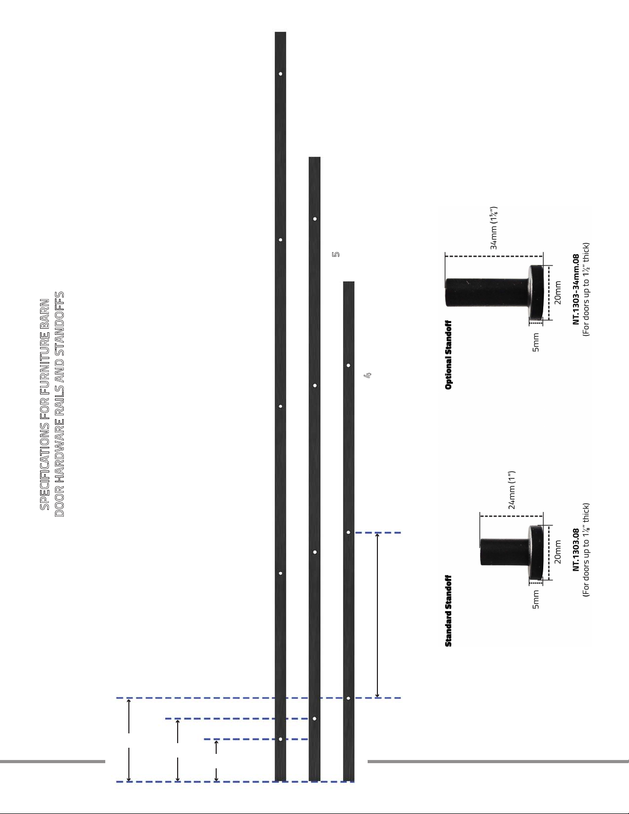
SPECIFICATIONS FOR FURNITURE BARN
DOOR HARDWARE RAILS AND STANDOFFS
(4’, 5’, & 6’ RAILS)
8”
6”
4”
16” cc
between holes for
all 3 rail sizes
NT.1302-72.08
NT.1302-72.SN
NT.1302-60.08
NT.1302-60.SN
NT.1302-48.08
NT.1302-48.SN
Custom Service Hardware
Revised:12/10/19
Rail Height = 1"
Rail Thickness = 1/8"
Rail Lengths = 48", 60", 72"
(5 ft.)
(6 ft.)
(4
ft.)
(Fastener hole locations pre-drilled in rails)
10
Page 11
111213
Page 12
Page 13
Page 14
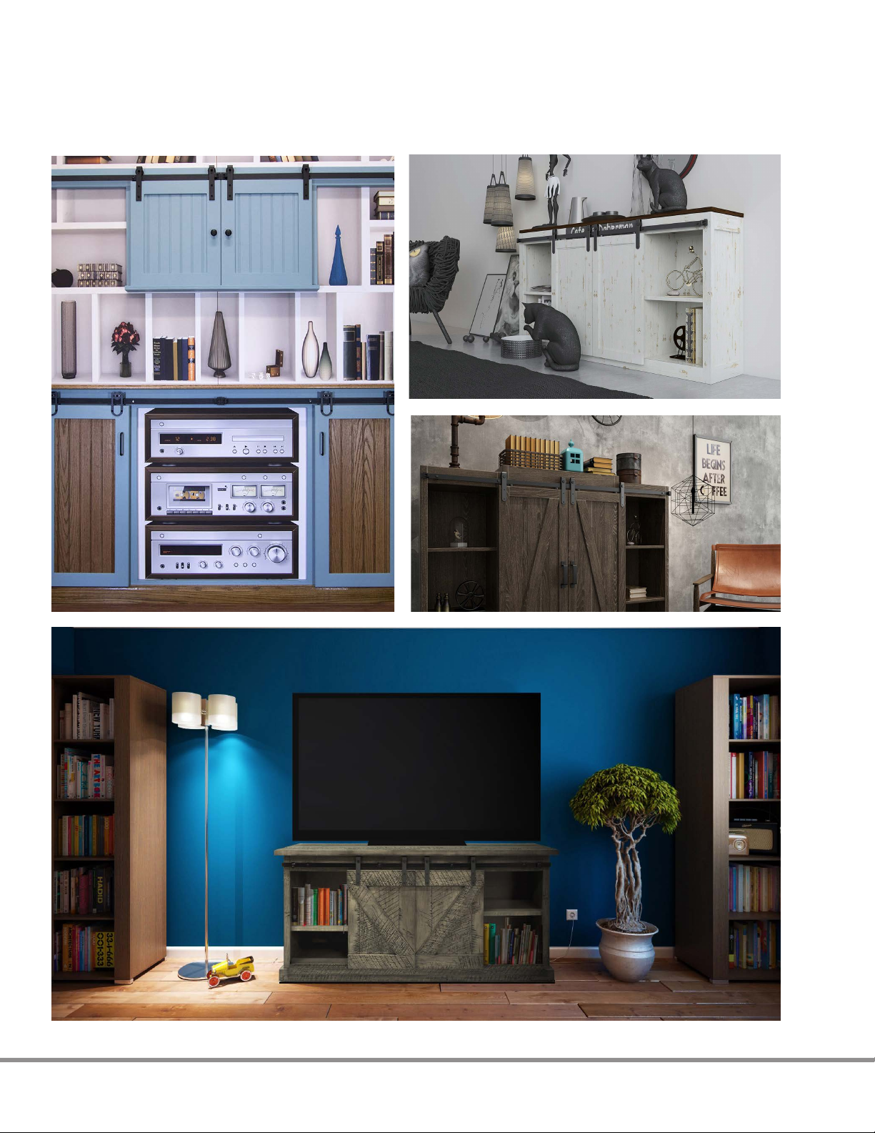
Application Photos of
Mini Barn Door Hardware
14
Page 15
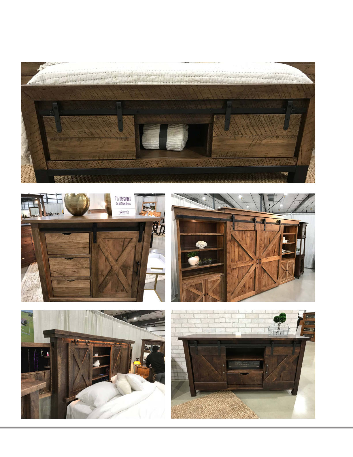
Mini Barn Door Hardware
in Previous Furniture Shows
15
 Loading...