

QuietCool IT-RFSWITCH-01, IT-RFHUB-01 Installation Manual

Rev 1.0
Page 1 of 4
O
verview
This document summarizes introductions for operating hub IT-RFHUB-01 and in-wall switch IT-RFSWITCH-01. Working as a paired set, IT-RFHUB-01
and IT-RFSWITCH-01 can remotely control the QuietCool Whole House Fans of QC Manufacturing Inc at up to three different speeds.
Key Specifications
IT-RFHUB-01 (Hub):
Voltage: 120V
Frequency: 60Hz
Motor load: 1HP, 735W (Max)
IT-RFSWITCH-01 (Switch):
Voltage: 3VDC (2 AAA batteries)
Battery Standby Current: ≤10uA
RF working distance: 100ft (no obstructions)
Warning:
- Disconnect power at the circuit breaker
before installing or servicing
- Use wires rated at least 105*C – copper
only
- Installation/wiring must be in accordance
with national and local code regulations
- Keep the enclosure cover closed at all
times when not servicing.
- Cover all unused wires with a wire
connector
FCC Regulations
This device complies with Part 15 of the FCC Rules. Operation is subject to the following two conditions: (1) this device may not cause harmful interference,
and (2) this device must accept any interference received, including interference that may cause undesired operation.
FCC Statement:
"This equipment has been tested and found to comply with the limits for a Class B digital device, pursuant to part 15 of the FCC Rules. These limits are
designed to provide reasonable protection against harmful interference in a residential installation. This equipment generates, uses and can radiate radio
frequency energy and, if not installed and used in accordance with the instructions, may cause harmful interference to radio communications. However,
there is no guarantee that interference will not occur in a particular installation. If this equipment does cause harmful interference to radio or television
reception, which can be determined by turning the equipment off and on, the user is encouraged to try to correct the interference by one or more of the
following measures:
—Reorient or relocate the receiving antenna.
—Increase the separation between the equipment and receiver.
—Connect the equipment into an outlet on a circuit different from that to which the receiver is connected.
—Consult the dealer or an experienced radio/TV technician for help."
FCC Caution:
Changes or modifications not expressly approved by the part responsible for compliance could void the user's authority to operate the equipment.
IT-RFSWITCH-01 Wall Switch & IT-RFHUB-01 Hub
Installation Guide
Rev 1.0
Page 2 of 4
Installation
In-wall Switch:
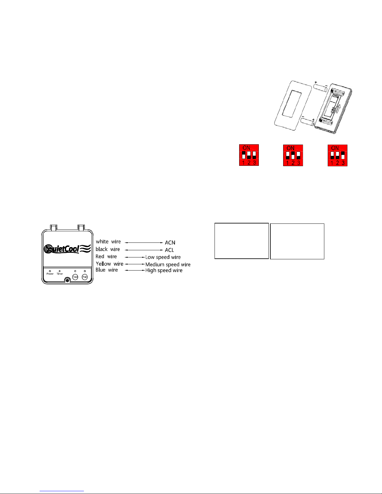
Fig. 1 Install Battery onto In—wall Switch
The in-wall switch is a standard decora style wall switch which can be fitted into a standard wall box or onto a wall-
mount base plate that comes with the switch.
As shown in Fig. 1, remove the front panel of in-wall switch, then install 2 pcs of AAA batteries into the holders.
Please make sure the battery polarity is correct. All the LED lights on the in-wall switch will be on for 3 seconds
and then go out, which means the in-wall switch operates properly. Install the front panel back onto the switch.
If LED lights are not on after batteries are installed, please check the battery status and try again.
IT-RFHUB-01 Hub:
(
Please switch off main power before wiring. The installation should be done by qualified
personnel only)
The hub (with a curved bottom) should be attached to the cylindrical fan housing and is wired to
the fan motor.
Remove the screw that holds down the hub cover and flip it up. Once the cover is open, a three
digit dip switch is available for fan speed configuration, as shown in Fig. 2.
Fig. 2 Dip Switch for Fan Speed Configuration
1 speed fan: Dial 1 to "ON”;
2 speed fan: Dial 2 to "ON”; and
3 speed fan: Dial 3 to "ON”
Once wiring is completed, close the hub cover and ti
ghten the screw.
Fig. 3 Connection Wires of IT-RFHUB-01
Input wires:
Black: Line voltage, ACL
White: Neutral, CAN
Output wires:
Red: Low speed
Yellow: Medium speed
Blue: High speed
 Loading...