

Page 1

Page 1 of 85
Page 2

TABLE OF CONTENTS
INTRODUCTION 3
CUSTOMER SERVICE 4
FEATURES 5
FRE-ASSEMBLY INFORMATION 6
REQUIRED TOOLS 7
HARDWARE & OPTIONAL ACCESSORIES 8
OTHER HARDWARE & OPTIONAL ACCESSORIES 9
OTHER REQUIREMENTS 11
PART LIST 12
SECTION 1: UPPER FRAMES 13
SECTION 2: LOWER FRAMES 28
SECTION 3: LANDING GEAR ASSEMBLY 41
SECTION 4: DRIVING SYSTEM 44
SECTION 5: TAIL ASSEMBLY 47
SECTION 6: CONTROL SYSTEMS 55
SECTION 7: ROTOR HEAD 60
SECTION 8: LINKAGE RODS AND SETTINGS 63
FRE-LIGHT CHECKS 78
WARNINGS 78
ADJUSTMENTS 79
HOW TO HOVER 80
HOW TO FLY FORWARD 81
AFTER FLIGHT CHECKS 83
WHAT IF THE HELICOPTER CRASHED 84
SPECIFICTION 84
Page 2 of 85
Page 3

INTRODUCTION
Congratulation and thank you for the purchase of great product! It is our sole desire for
you to enjoy the quality workmanship and performance of any of our Nitro powered
helicopters. We believe we have the latest designs and technology incorporated into our
model helicopters. Our CNC parts are produced using the best high density materials &
anodized using material hardening finishes with the tightest of tolerances. Our new
helicopters feature the latest advances in R/C helicopter design. The simple and
mechanically superior EMS design (also known as CCPM) ensures a helicopter that will
be more responsive and more stable than any other R/C helicopter you have ever
flown. Three servos are attached directly to the Swashplate to ensure precise control.
This kit features all metal construction, and a carbon or composite frames are standard.
Along with great products, our staffs are RC guys that fly and have hands on experience
with total manufacturing & testing of our helicopters. In addition, we stand behind all our
products 100% with satisfaction guaranteed. Our kits will be shipped 100% complete
and we can assure you that once you fly your helicopter you will love it.
The Super Learner
We believe you hold in your hands one of the best helicopters manufactured in the world
today. The brand new Super Learner is the newest version of our Big Nitro
Quick line. It is a bigger, stronger frames, yet powerful machine. This baby delivers
amazing power smoothly throughout the entire range of its nitro motor. It functions so
responsive and stable. The Super Learner Pro version features a fully
machined dual-spindle head, metal tail rotor, metal grips, carbon fiber frames, bigger
carbon rudder push rod, and carbon fiber boom supports. The Super Learner
Sport version features a G10 fiberglass frame, fully machined metal head,
carbon boom supports, carbon rudder push rod, and molded tail blade grips. Our
helicopters are carefully designed and tested, and manufactured of the highest quality
materials available.
In a short time, you can be flying.
We ask that you please read the entire manual before starting the construction of the
Super Learner, and if you have any questions our technical support staff can be
reached at
(610) 282-4811 M-F 9-6, S 9-4 Eastern time,
or by email at
For the latest information and updates, please visit our website at
www.quickworldwide.com
Page 3 of 85
Page 4

CUSTOMER SERVICE
Quickworldwide
201 South 3
rd. St. & 309 N.
Coopersburg, PA 18036
Phone: (610)-282-4811
Fax: (610)-282-4816
Office Hours:
Mon – Fri: 8:30 – 6:00
Sat: 8:30 – 1:30
(Eastern Daylight Time)
Technical Support Personnel:
Chuck – [email protected]
Jon –
Websites:
http://www.hhiheli.com
http://www.quickheli.com
http://www.giantscaleplanes.com
E-mail:
Page 4 of 85
Page 5

FEATURES
Super Learner
1. Frame Construction: Super Learner frames are made of the highest quality Carbon
Fiber or Black G-10. These frames are not only thick and rigid but will provide excellent vibration
absorption.
One-Way Hex Start Shaft System: The one-way bearing allows the engine to
2.
continue to run after the starter motor has been stopped.
3. Constant Tail Rotor Drive System: provides full tail authority during motor off
maneuvers.
4. Belt driven Tail: Smooth, reliable, and low maintenance.
5. High Quality Ball Bearings: Super Learner offers high quality ball bearings on all
moving parts.
6. EMS Collective System: The EMS Collective design allows ease of setup with
fewer moving parts. EMS demonstrates overall design simplicity and represents the future of
helicopter technology.
7. Heavy-Duty Clutch System: Based on the same design as our famous heavy-
duty clutch upgrade that fits most popular machines, this clutch will give many years of problem
free operation.
7. Control Linkages: The control linkages are high quality 2.3mm stainless steel rods
with Delrin® acetal resin rod ends.
8. Single Blade Axle Design: simple, very responsive, with exceptionally consistent
flight characteristics.
9. Advanced Airfoil Fly-bar Paddles: These paddles will provide the best flight
characteristics for both 3D & Sport flying: Smooth forward flight, with quick response upon
demand.
10. Rearward facing Engine Design: This design provides quick access to the
glow plug and is advantageous for easy engine removal.
11. Heavy-Duty Bearing Blocks: Bearing Blocks is specially designed for this model.
They couple to high quality bearings to carry and support all high speed moving operations.
Page 5 of 85
Page 6

PRE-ASSEMBLY INFORMATION
Warning
The radio-controlled model helicopter contained in this kit is not a toy.
Rather, it is a sophisticated piece of equipment. This product is not recommended for
use by children without adult supervision. Radio controlled models such as this are
capable of causing both property damage and/or bodily harm to both the
operator/assembler and spectators if not properly assembled and operated. Hobbies &
Helis assumes no liability for damage that could occur from the mis-assembly and/or
use/misuse of this product.
Academy of Model Aeronautics
We strongly encourage all prospective and current R/C aircraft pilots to join the
Academy of Model Aeronautics. The AMA is a non-profit organization that provides
services to model aircraft pilots. As an AMA member, you will receive a monthly
magazine entitled Model Aviation, as well as a liability insurance plan to cover against
possible accident or injury. All AMA charter aircraft clubs require individuals to hold a
current AMA sporting license prior to the operation of their model. For further information,
please contact AMA at:
Academy of Model Aeronautics
5161 East Memorial Drive
Muncie, IN 47302-9252
USA
Phone: (317) 287-1256
www.modelaircraft.org
Before you begin
Quick Helicopter kits are packaged with care and attention to detail. We recommend
when you are ready to begin building this model that you examine the kit carefully,
inspect the contents of each package, and read and understand these instructions
thoroughly before starting assembly. It is suggested that you purchase a parts box for
the small fasteners and hardware, or use small bowls or other containers.
Page 6 of 85
Page 7
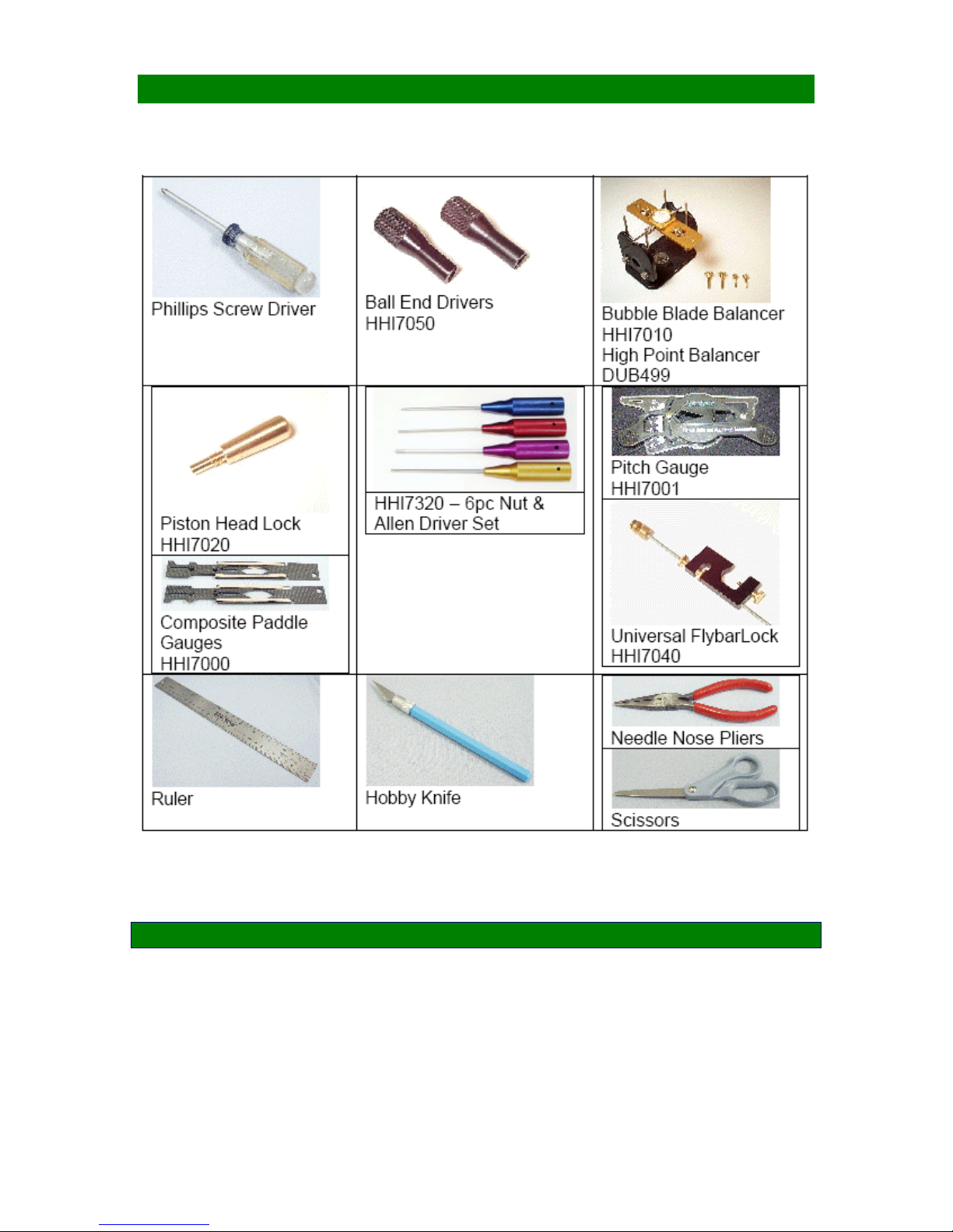
REQUIRED TOOLS
Page 7 of 85
Page 8
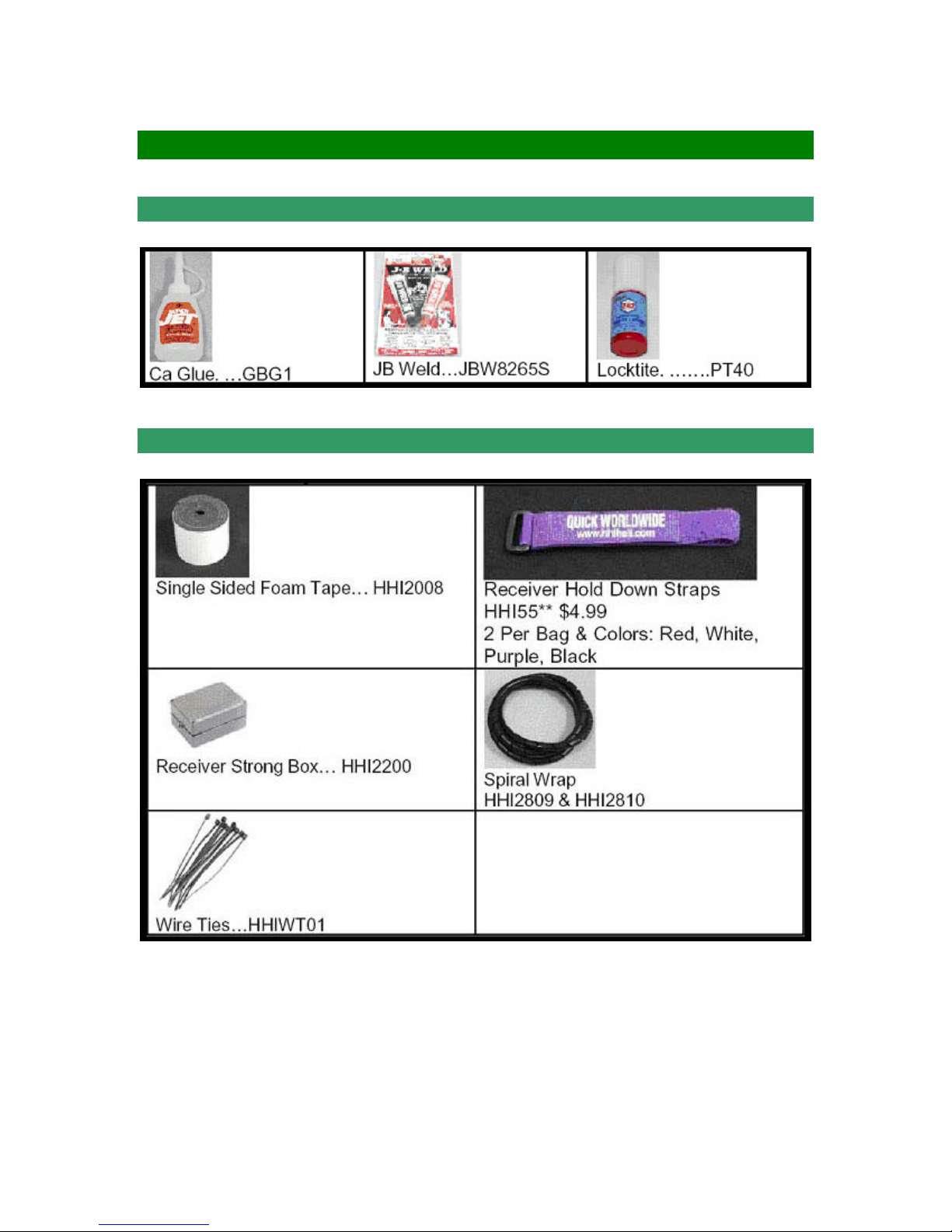
HARDWARE & OPTIONAL ACCESSORIES
GLUES AND THREAD LOCK COMPOUNDS
RADIO MOUNTING ACCESSORIES
Page 8 of 85
Page 9
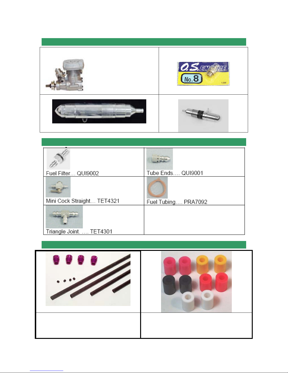
ENGINES, GLOW PLUGS, AND EXHAUST SYSTEM
ENGINES: we recommend OS46SX but others may work
GLOW PLUGS: OS # 8…OSMG2691
One-Piece Muffer
FUEL SYSTEM
Two-Piece Muffer
OTHER HARDWARE & OPTIONAL ACCESSORIES
3MM FLYBAR STIFFENERS
HHI 402
30 SIZE SKID STOPS
HHI 200 AVAILABLE IN COLORS
Page 9 of 85
Page 10
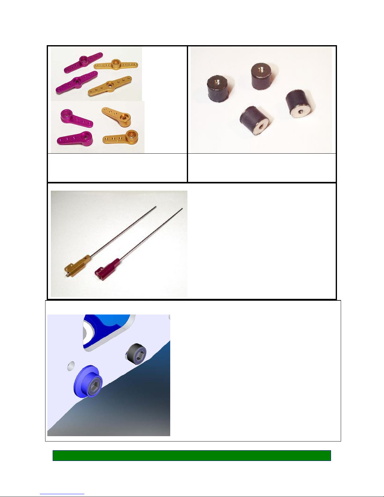
W
W
SERVO ARM SET
LANDING GEAR DAMPENERS
HHI 2004
BASE LOAD ANTENNA
HHI 53**
AVAILABLE IN BLUE, GOLD,
PURPLE
AND IN 40, 50, AND 72 Mhz
FINISHING CAPS
• Adds color and style
• Distributes force across larger surface area
ITH
ITHOUT
3mm 4mm
(20 pcs in a package) (8 pcs in a package)
BLACK HHIM11100B --BLUE HHIM11103 HHIM11108
GOLD HHIM11101 HHIM11106
GREEN HHIM11100G --PURPLE HHIM11100 HHIM11105
RED HHIM11100R --SILVER HHIM11100 HHIM11107
Page 10 of 85
Page 11

OTHER REQUIREMENTS
Radios:
Any radio that supports EMS/CCPM Mixing will work fine. Hobbies & Helis & its
distributors carry various lines of helicopter radios.
Note: Please consult the instruction for your Gyro for setting the overall travel
and limits to ensure proper operation and travel of Tail Pitch Slider.
Servos:
Any sport servo will offer acceptable performance. However, because servos
operate all critical functions of the helicopter, they can be the single most
important component that contributes to proper function of the helicopter. Due to
the nature of EMS collective, we suggest the use of digital servos to enhance
and ensure matched servo timing without servo interaction
Locktite Warning (CRITICAL):
.
This is a general warning about the use of Locktite and its
importance. Locktite must be used anywhere that a metal
fastener i.e. (M2, M3, M4 Cap Head Bolts, Set Screws etc.) is
threaded into a metal part i.e. (Bearing Blocks, Cross-members,
etc.). Failure to use Locktite can result in loosening of critical
operating components, loss of control of the model, and can
lead to a crash.
Page 11 of 85
Page 12

PART LIST
• In your kit, parts are bagged according to each major assembly and are labeled “Bag
1, Bag 2, etc.” You will note that the heading for each assembly indicates which bag
correlates with each assembly.
• For a good installation, only open up the bag that you need for particular assembly.
• Please check the parts in that bag against the parts list shown for each assembly as
well as each subassembly to make sure there are no missing parts.
• Small parts such as nuts and bolts can be put into containers or trays to prevent
losing parts.
• Part No. with ***** means that part is not included in the kit.
• The colors of drawings in this manual may look different from the parts you have in
the kit.
No. Bag No. Description Quantity Check
1 Bag 1 For Upper Frame Assembly 1
2 Bag 2 For Lower Frame Assembly 1
3 Bag 3 Landing Gear 1
4 Bag 4 Driving System 1
5 Bag 5 For Tail Assembly 1
6 Bag 6 Control System 1
7 Bag 7 Rotor Head 1
8 Bag 8 Linkage & Settings 1
9 Frame Frame 1
Canopy
Carbon Push Rod
Tail Gear Belt
Tail Boom
10 Loose in Box
11 HB Hardware Bag 1
Flybar
Decal Sheet
Instruction CD
Fuel Tank & Accessories
Fan Shroud
1
1
1
1
1
1
1
1
1
Page 12 of 85
Page 13
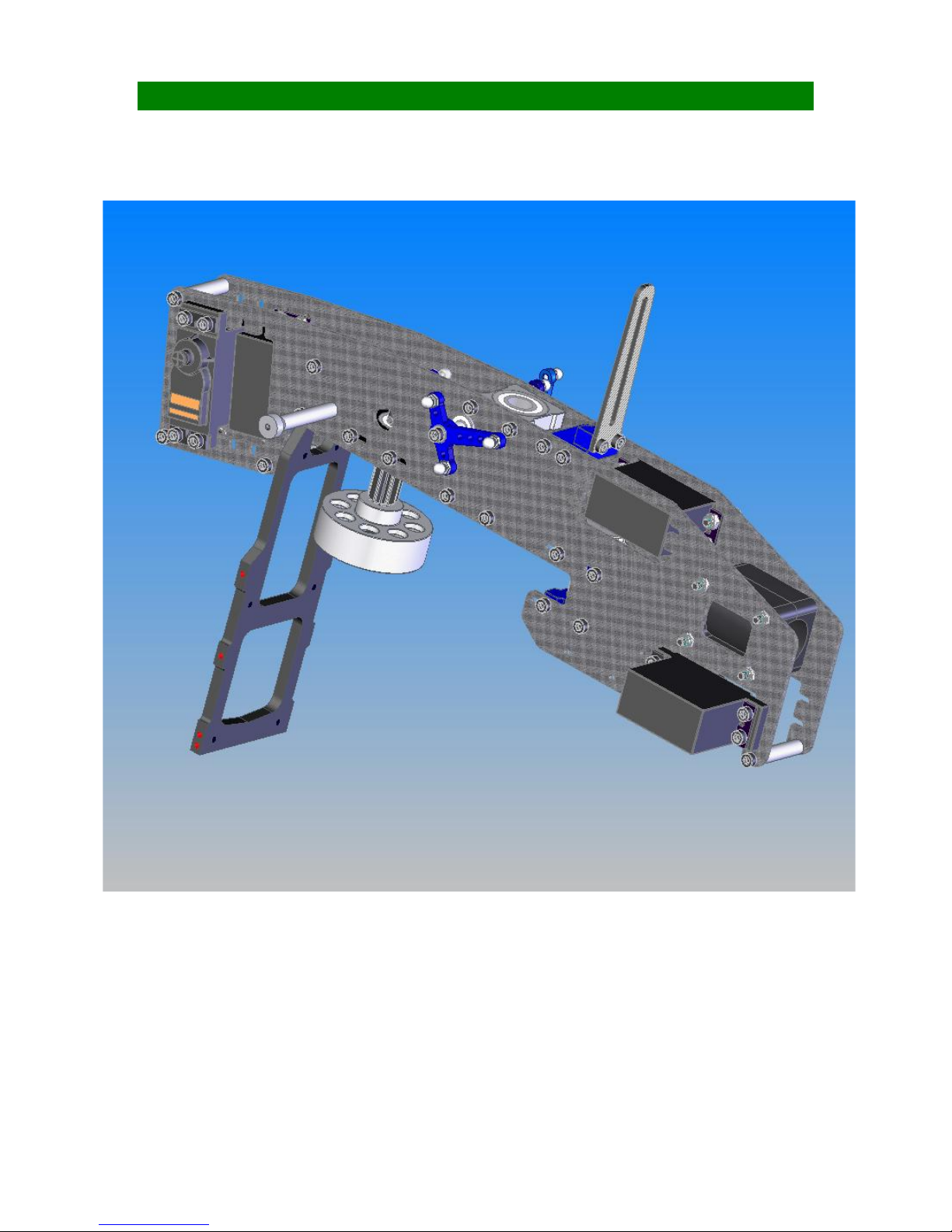
SECTION 1: UPPER FRAMES Bag 1
Page 13 of 85
Page 14
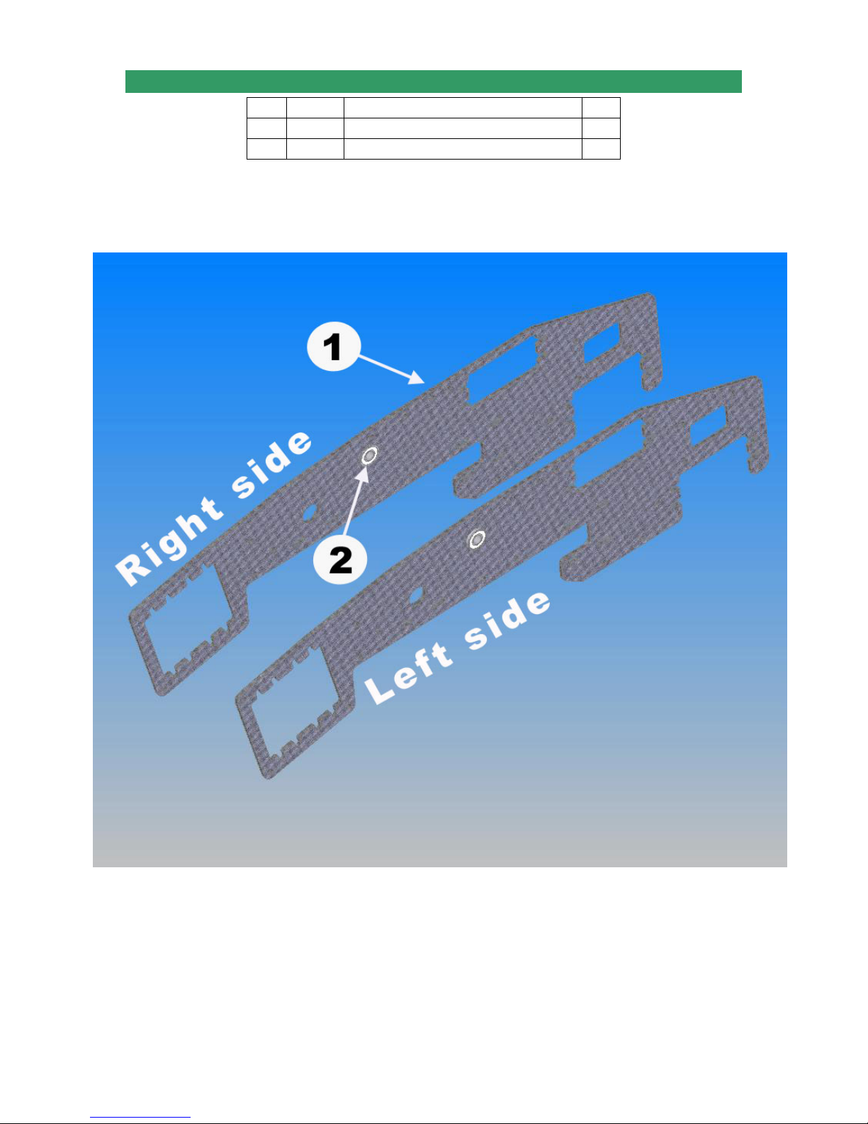
1-1 ELEVATOR SHAFT BEARINGS
No. Bag# Description Qty
1 Frame Upper Frame (from Frame Bag) 2
2 1 5X10X4Flanged Bearing 2
Note: The holes on the frames are designed for “push-fit” feature. Sometime you may have to
sand them a little bit before pushing the bearings in. The bearing flange mates against the
inside of the frames.
Page 14 of 85
Page 15
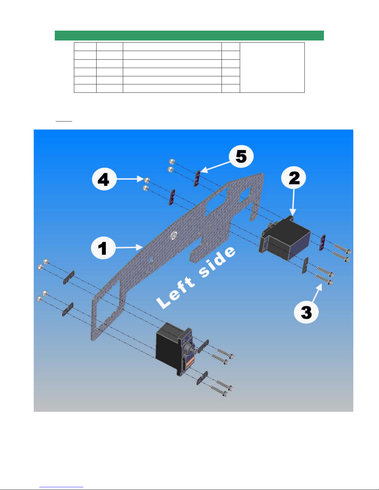
1-2 LEFT AILERON & RUDDER SERVO SUBASSEMBLY
No. Bag# Description Qty
1 Step 1-1 L. Upper Frame Subassembly 1
2***** Servo 2
3 HB* M2.5x14 Cap Head Bolt 8
4 HB M2.5 Locknut 8
5 HB Fixing Plate 8
***** Part No. with ***** means that part is not included in the kit.
*HB stands for Hardware Bag
Note: Be sure to use the rubber grommets and eyelets that are provided by the servo
manufacturer. Output Shaft of Rudder Servo should be toward the boom.
Remember to apply
Loctite for the Srews
( see Locktite Warning on
page 11)
Page 15 of 85
Page 16
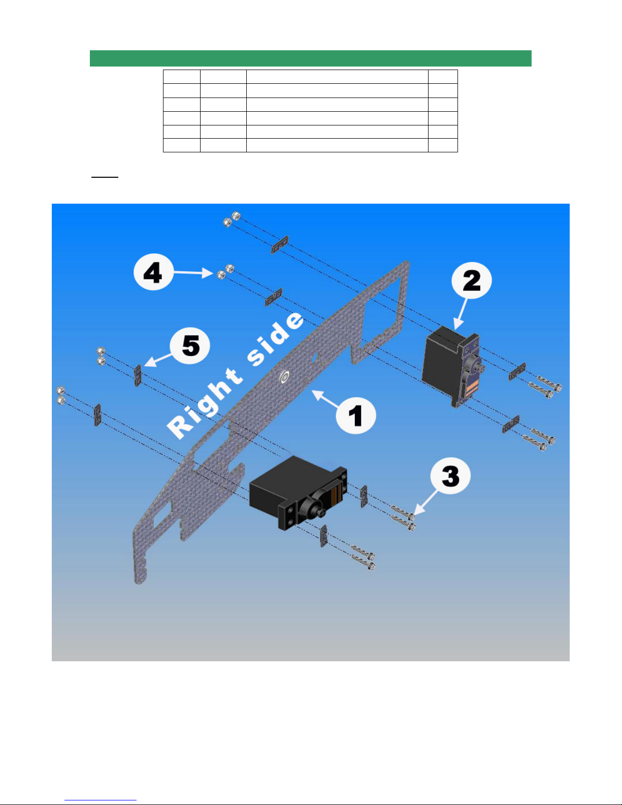
1-3 RIGHT AILERON & ELEVATOR SERVO SUBASSEMBLY
No. Bag# Description Qty
1 Step 1-1 R. Upper Frame Subassembly 1
2***** Servo 2
3 HB M2.5x14 Cap Head Bolt 8
4 HB M2.5 Locknut 8
5 HB Fixing Plate 8
***** Part No. with ***** means that part is not included in the kit.
Note: Be sure to use the rubber grommets and brass eyelets that are provided by the
servo manufacturer.
Page 16 of 85
Page 17
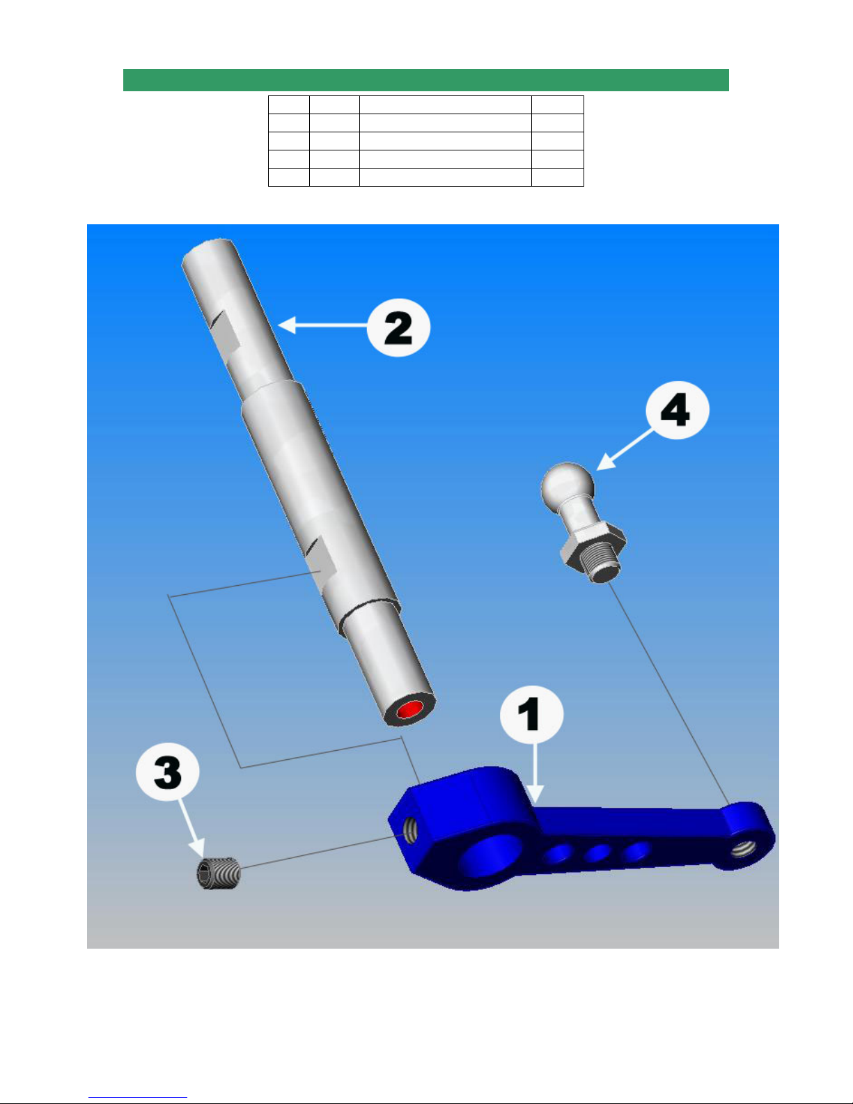
1-4 INNER ELEVATOR CONTROL ARM SUBASSEMBLY
No. Bag # Description Qty
1 1 Inner Elevator Control Arm* 1
2 1 Elevator Control Shaft 1
3 HB M3x5 Set Screw 1
4 HB M3x7 Pivot Ball Stud 1
Note: Quick Super Learner 37 has shorter Inner Elevator Control Arm.
Page 17 of 85
Page 18

1-5 TAIL TRANSMISSION ASSEMBLY
No Bag# Description Qty
1 1 Counter Gear 1
2 1 Counter Gea r Shaft 1
3 HB M3X5 Set Screw 2
4 1 Pulley Gear 1
5 1 Counter Gear Bearing Block 2
-Install Counter Gear to Counter Gear Shaft using M3x5
Set Screw (No. 3) to secure it.
-Put Counter Gear Bearing Block (Lower one ) in with the
Flange facing down
-Install Counter Gear Bearing Block (Upper one) with the
Flange facing down
-Install Pulley Gear and secure it with M3x5 Set Screw
Page 18 of 85
Page 19
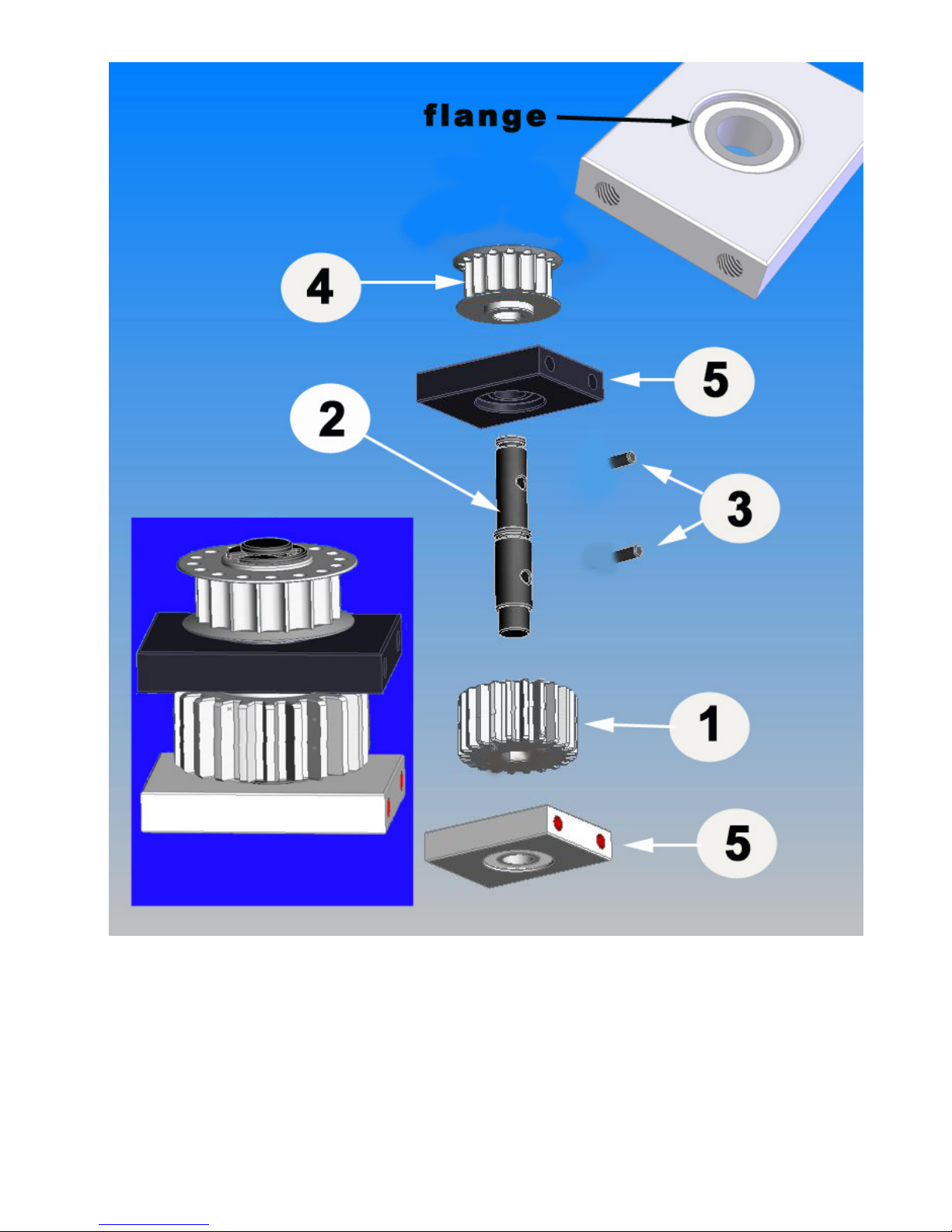
Note: Bearing Blocks shown may look differently.
Page 19 of 85
Page 20
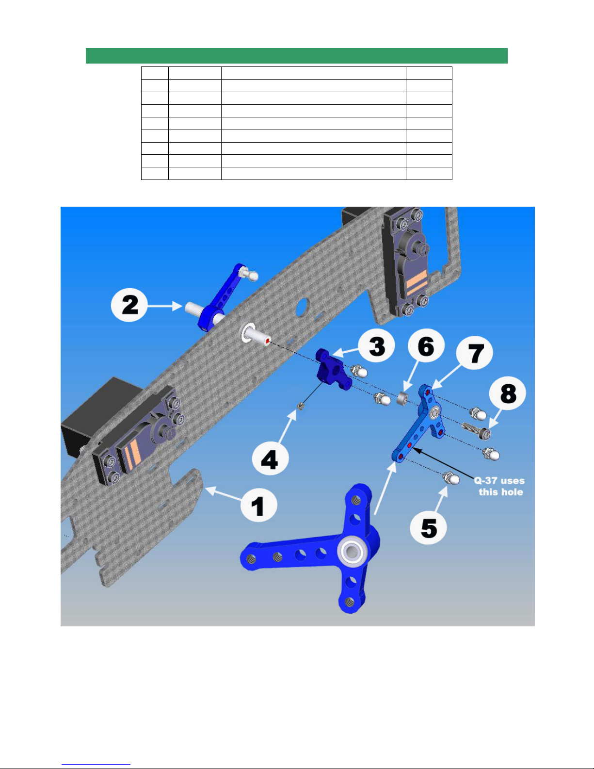
1-6 ELEVATOR CONTROL ARM-RIGHT SIDE
No. Bag# Description Qty
1 Step 1-3 R. A&E Arm Subassembly (step 1-3) 1
2 Step 1-4 Inner El. Ctrl. Arm Subassembly (step 1-4) 1
3 1 Outer Elevator Control Arm 1
4 HB M3x5 Set Screw 1
5 HB M3x4 Pivot Ball Stud 5
6 HB M3x5x3 Spacer 1
7 1 Right Aileron Control Lever 1
8 HB M3x14 Cap Head Bolt 1
Note: For Quick Super Learner 37, install the 3x4 Pivot Ball Stud into the 2
instead of the first hole for correct timing.
Page 20 of 85
nd
hole
Page 21
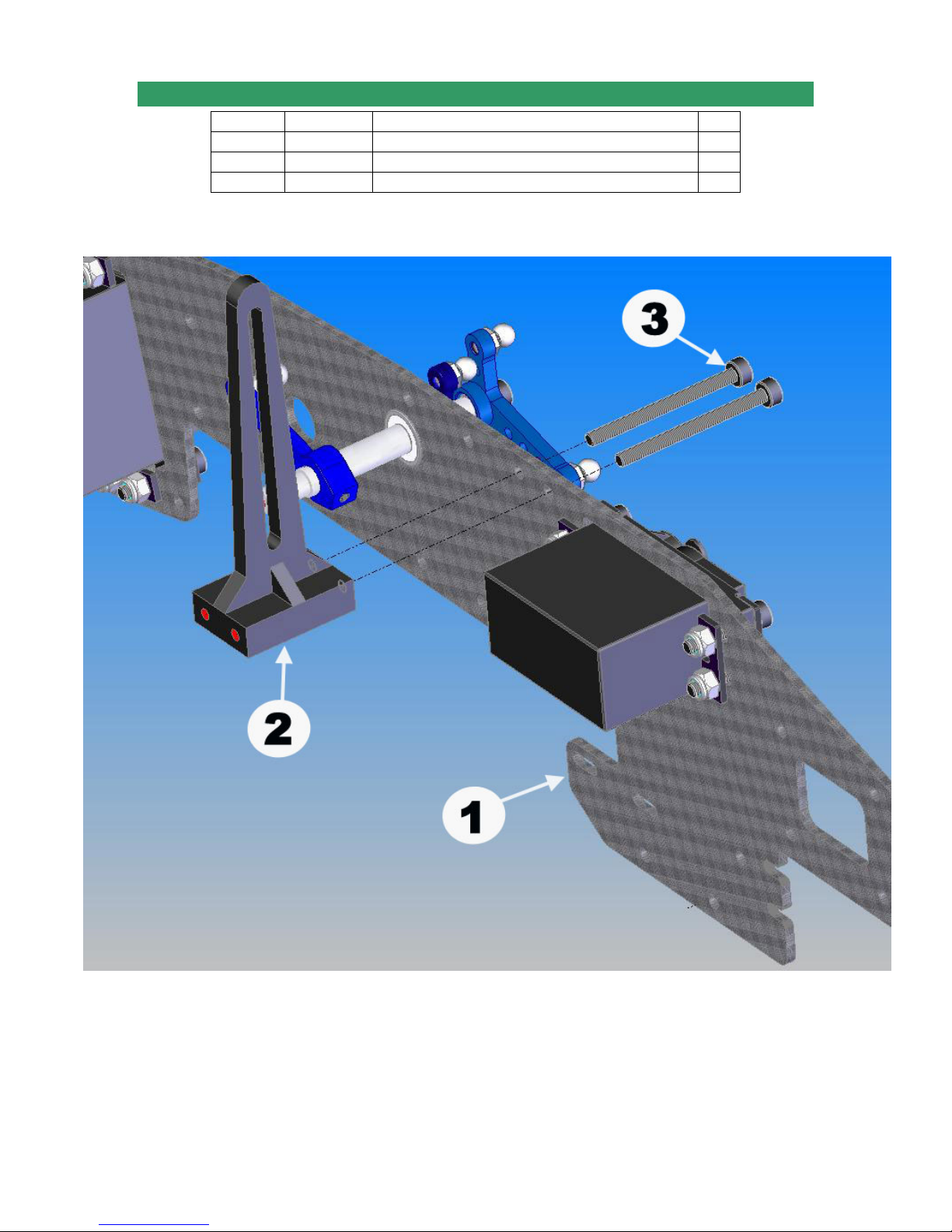
1-7-A ANTI-ROTATION GUIDE ASSEMBLY SPORT VERSION
No. Bag# Description Qty
1 Step 1-6 Right Upper Frame Subassembly 1
2 1 Washout Anti-Rot. Guide 1
3 HB M3x35 Cap Head Bolt 2
Page 21 of 85
Page 22
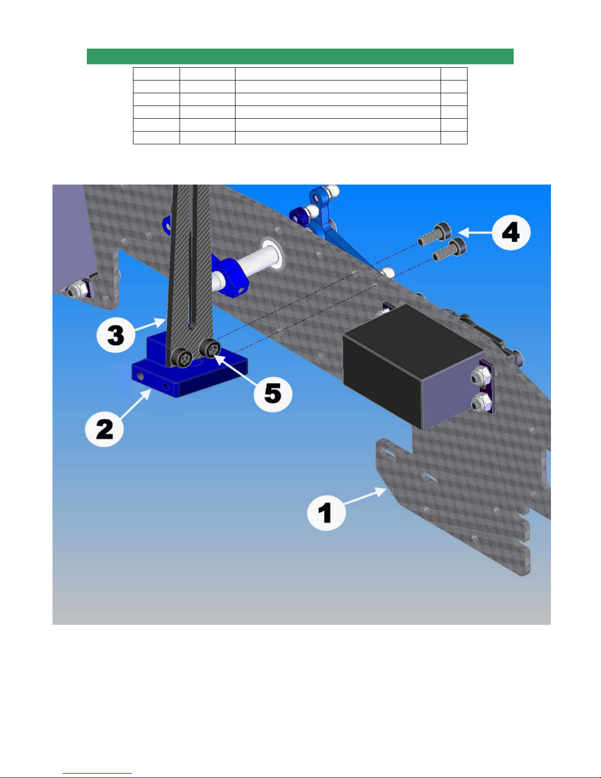
1-7-B ANTI-ROTATION GUIDE ASSEMBLY PRO VERSION
No. Bag# Description Qty
1 Step 1-6 Right Upper Frame Subassembly 1
2 1 Washout Anti-Rotation Guide Base 1
3 Frame Washout Anti-Rotation Guide 1
4 HB M3x8 Cap Head Bolt 2
5 HB M3x6 Cap Head Bolt 2
Page 22 of 85
Page 23
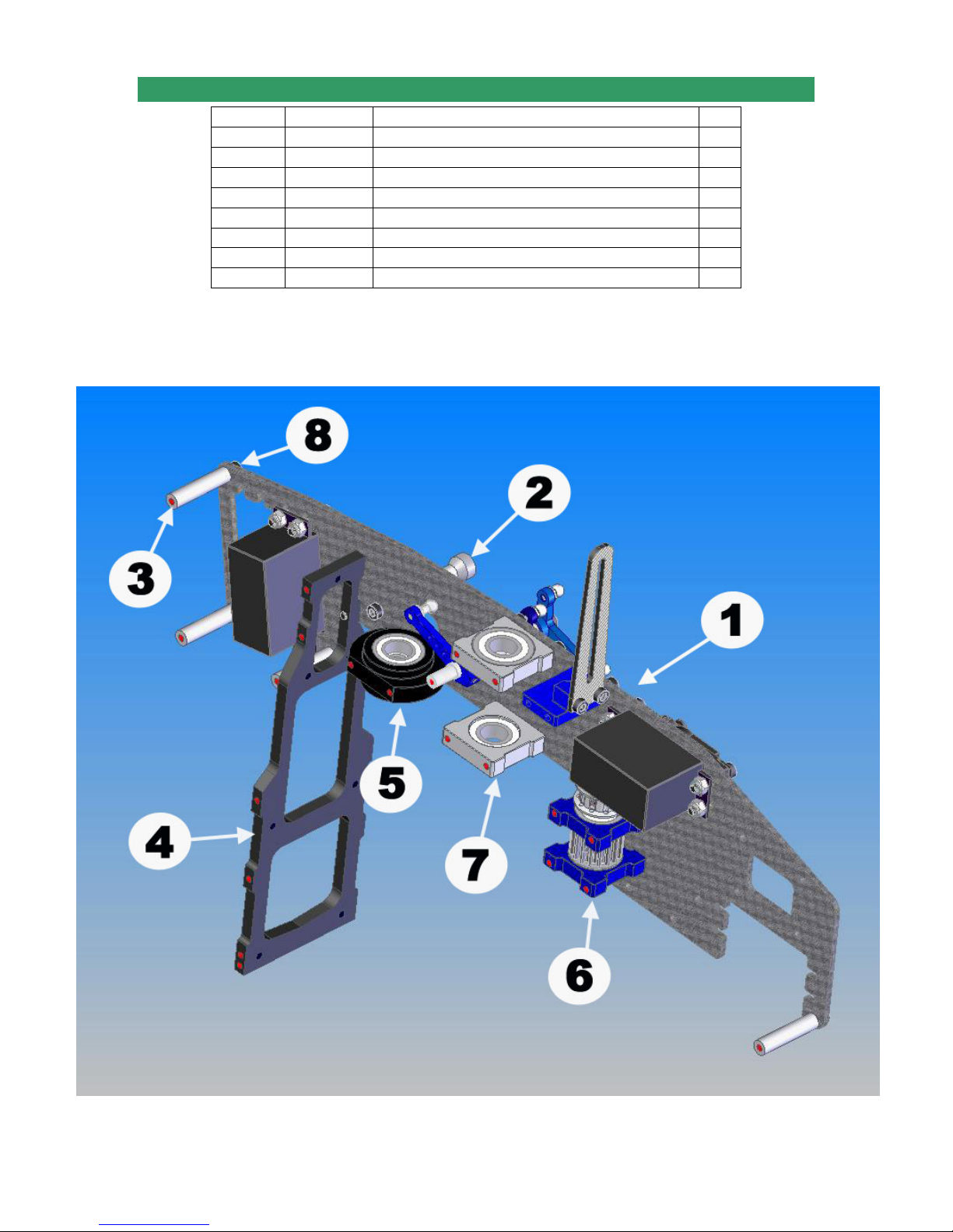
1-8 RIGHT SIDE ASSEMBLY
No. Bag# Description Qty
1 Step 1-7 Right Upper Frame Subassembly 1
2 1 Short Canopy Standoff 1
3 1 M3x26 Cross Member 4
4 Frame Bulkhead 1
5 1 Clutch Bearing Block 1
6 Step 1-5 Tail Transmission Assembly 1
7 1 Main Shaft Bearing Block 2
8 HB M3x8 Cap Head Bolt 17
Note: the flange of the Upper Main Shaft Bearing Block should face down and the one of the
Lower Bearing Block should face up. For the Clutch Bearing Block, the side with the smaller
bearing should be face up.
Page 23 of 85
Page 24
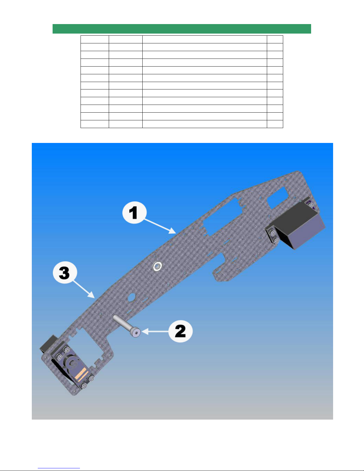
1-9 UPPER FRAME INSTALLATION
No. Bag# Description Qty
1 Step 1-2 Left Upper Frame Assembly 1
2 1 Short Canopy Standoff 1
3 HB M3x8 Cap Head Bolt 19*
4 Step 1-8 Right Upper Frame Assembly 1
5 1 Boom Holder 2
6 HB M3x35 Cap Head Bolt 4
7 HB M3 Locknut 4*
8 1 Left Aileron Arm Control Lever 1
9 HB M3x4 Pivot Ball Stud 3
10 HB M3x5x3 Spacer 1
11 HB M3x14 Cap Head Bolt 1
*Note: For the Sport Version, you need 17 M3x8 Cap Head Bolts and 6 M3 Locknuts.
Page 24 of 85
Page 25
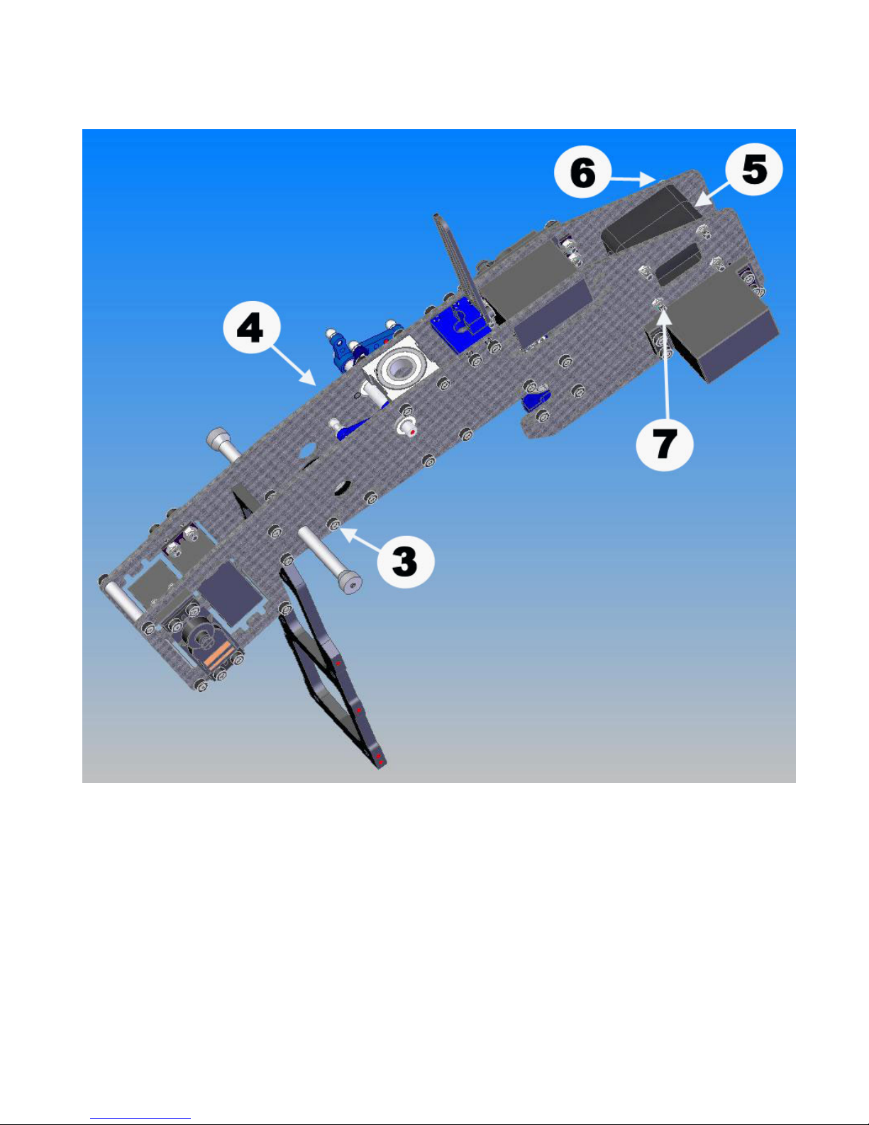
Attach the right side and left side together using M3x8 Cap Head Bolts and M3 Locknuts. For
the Boom Holder, keep the locknuts loose for installing the Tail later.
Page 25 of 85
Page 26
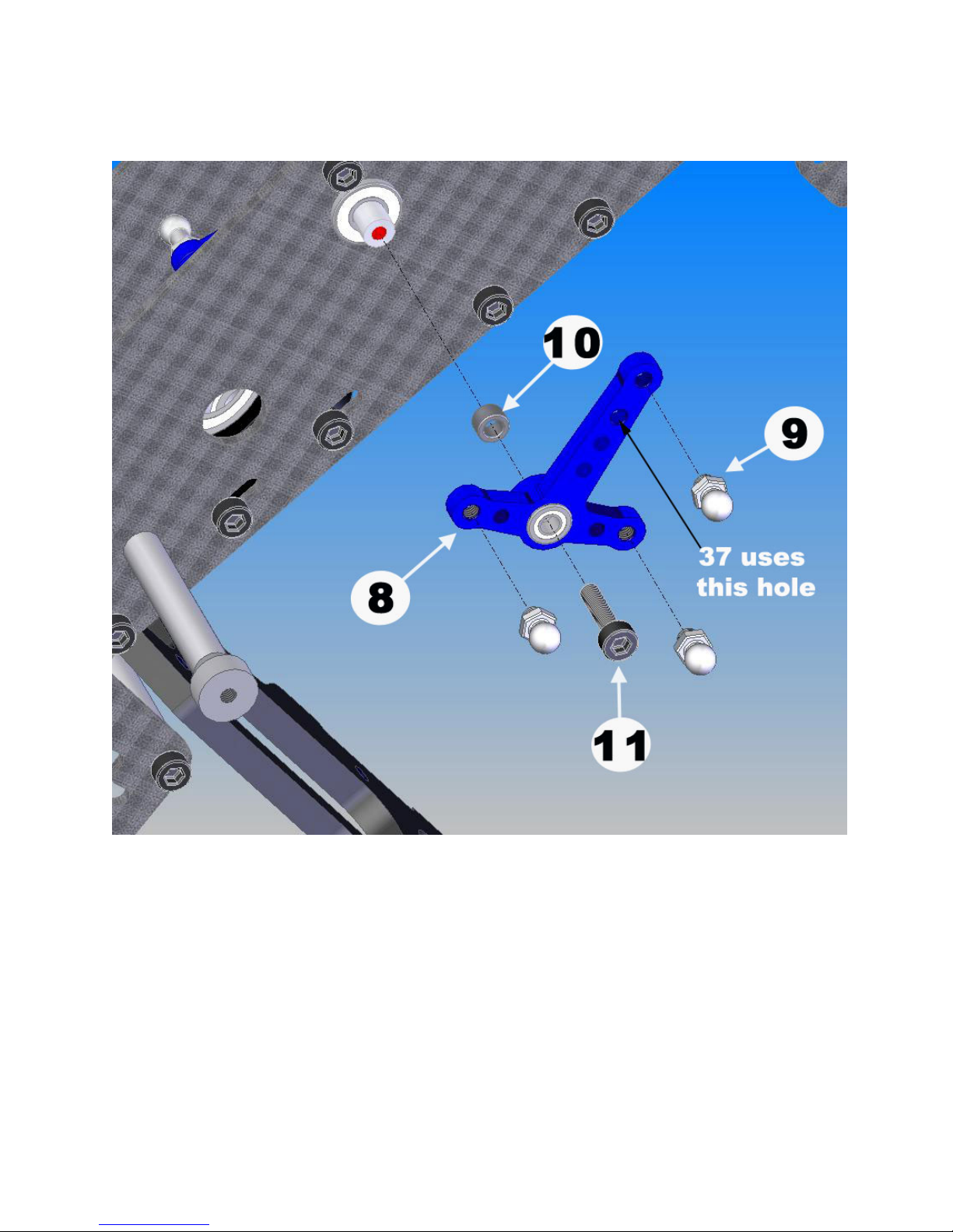
Note: For Quick Super Learner 37, install the 3x4 Pivot Ball Stud into the 2nd hole
instead of the first hole for correct timing.
Page 26 of 85
Page 27
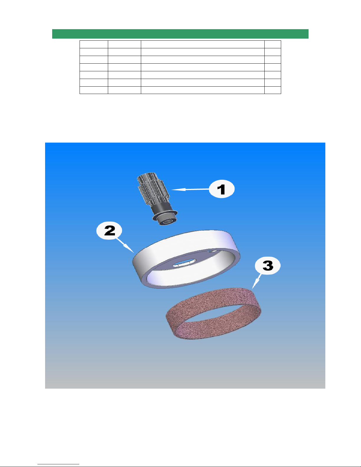
1-10 CLUTCH ASSEMBLY
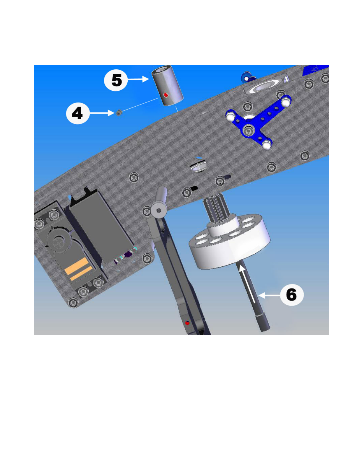
No. Bag# Description Qty
1 1 Pinion Gear 1
2 1 Clutch Bell 1
3 1 Clutch Shoe Lining 1
4 HB M4x4 Set Screw 1
5 1 Start Coupler 1
6 1 Start Shaft 1
Install (1) Clutch Lining into (1) Clutch Bell. Note: The recommended adhesives
for installing the clutch lining are JB Weld or 10 Min + Epoxy. Prepare the clutch
bell by scuffing the interior with an x-acto blade or sand paper. Apply the
adhesive thin and even and finish the installation by inserting and finishing the
clutch lining.
Page 27 of 85
Page 28
Page 28 of 85
Page 29
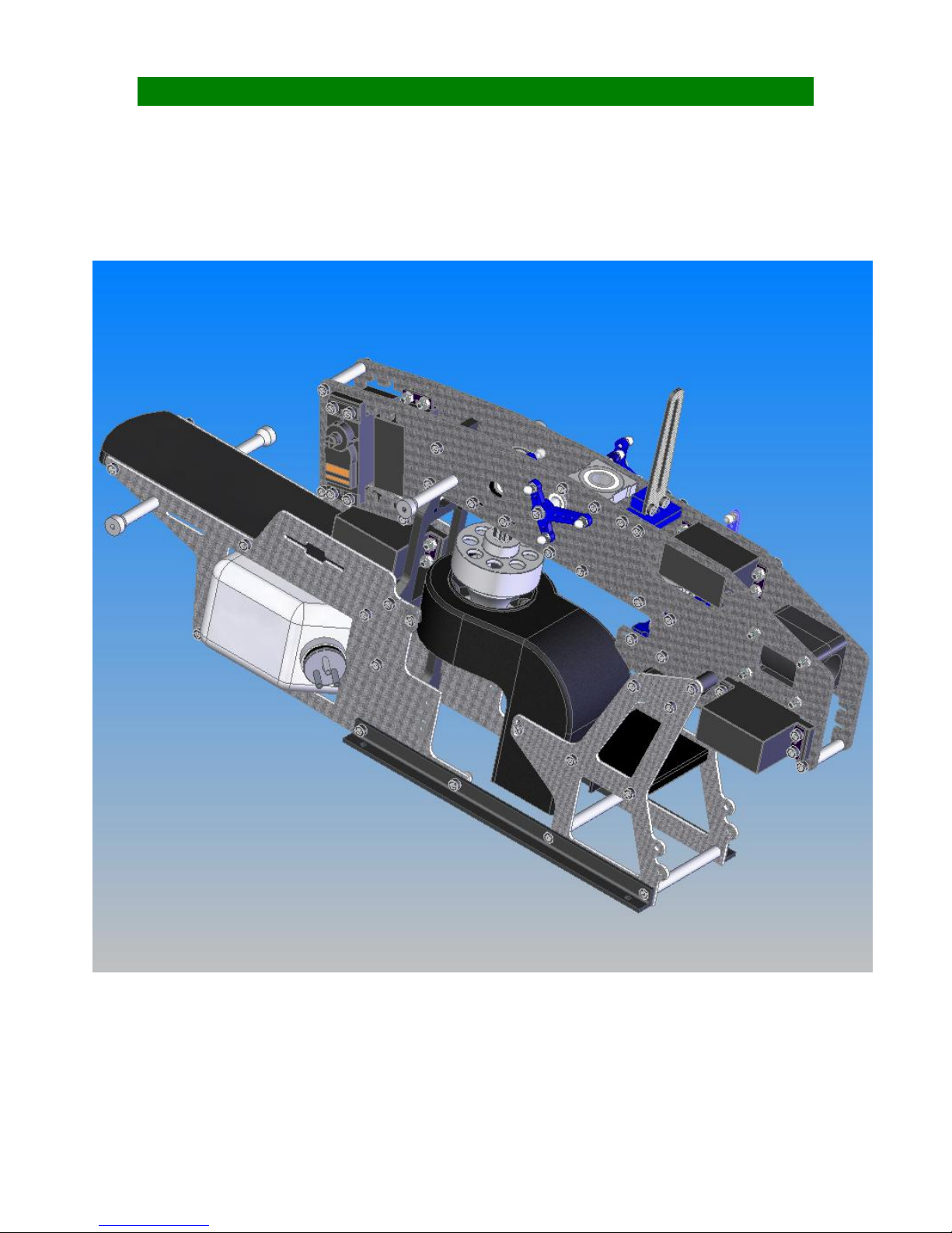
SECTION 2: LOWER FRAMES Bag 2
Page 29 of 85
Page 30
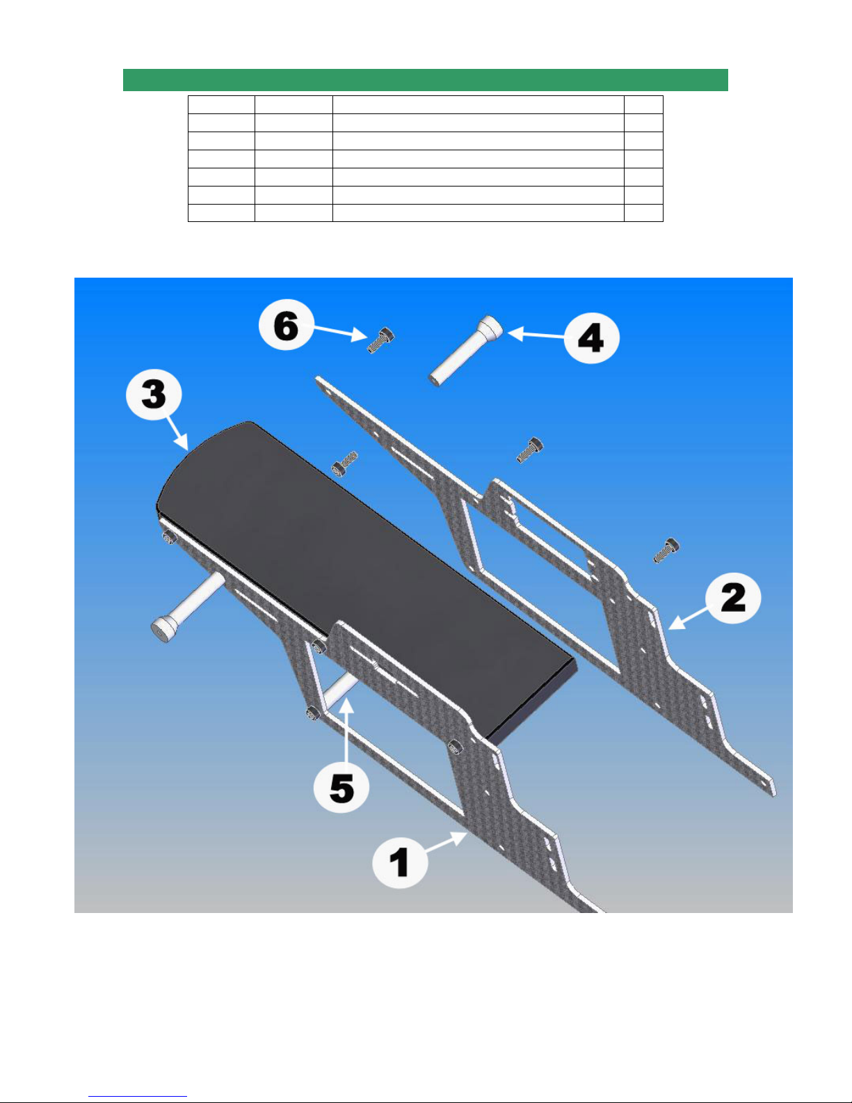
2-1 RADIO TRAY ASSEMBLY
No. Bag# Description Qty
1 Frame Left Front Lower Frame 1
2 Frame Right Front Lower Frame 1
3 Frame Radio Tray 1
4 2 Long Canopy Standoff 2
5 2 M3x54 Cross Member 1
6 HB M3x8 Cap Head Bolt 10
Page 30 of 85
Page 31
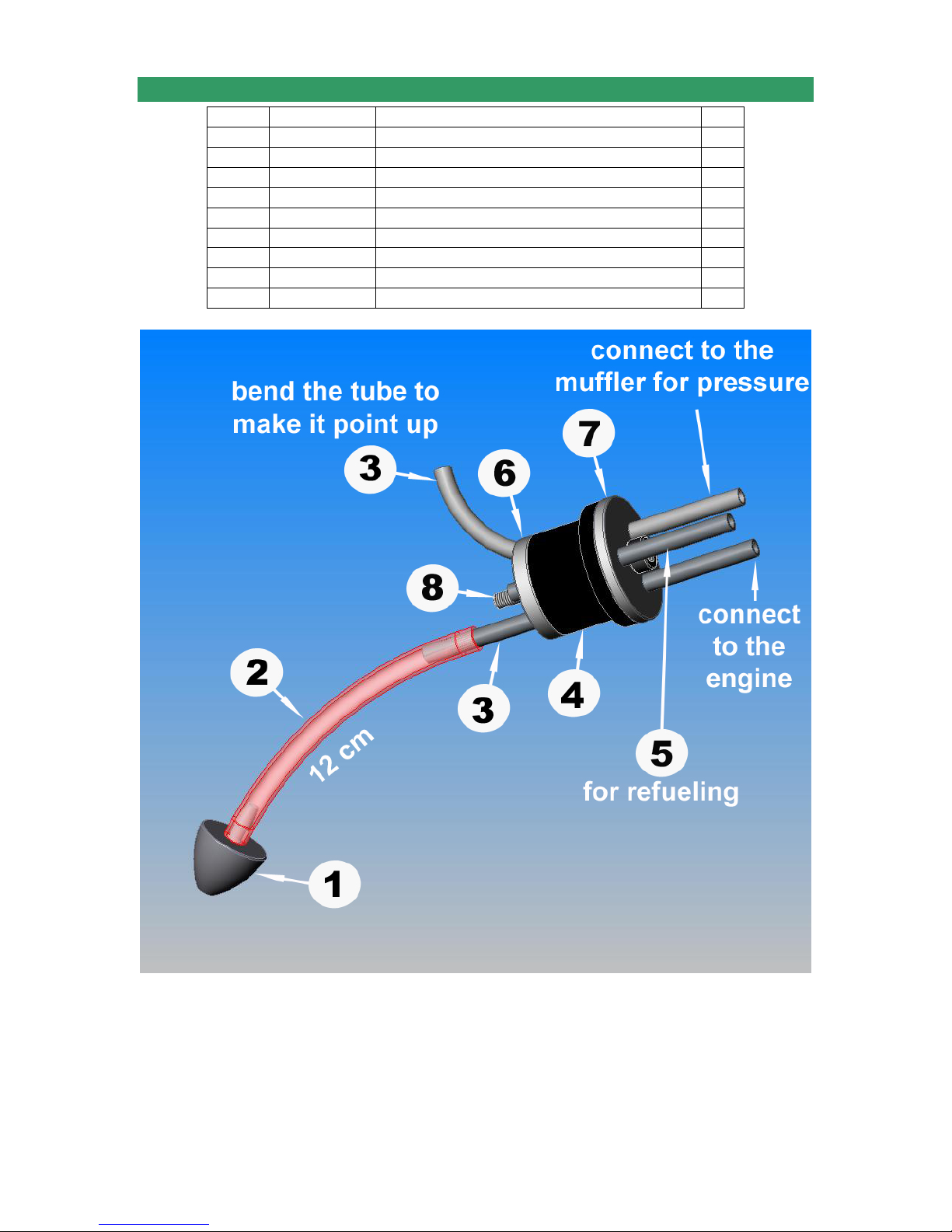
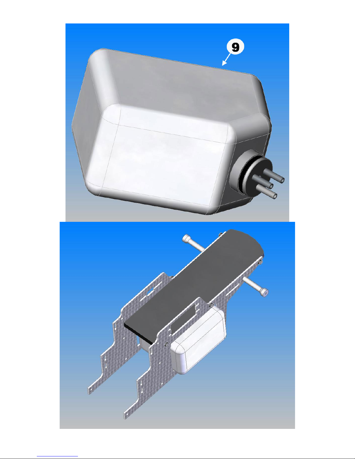
2-2 FUEL TANK ASSEMBLY
No. Bag# Description Qty
1 Loose in box Tank Clunk 1
2***** 12 cm Hose 1
3 Loose in box Long Tube 2
4 Loose in box Tank Rubber Plug 1
5 Loose in box Short Tube 1
6 Loose in box Tank Fuel Plug Bottom Flange 1
7 Loose in box Tank Fuel Plug Top Flange 1
8 Loose in box M3x25 Cap Head Bolt 1
9 Loose in box Fuel Tank 1
• There are three (3) lines (Aluminum fuel tubing) that need to be constructed for
the tank assembly. Depending on the engine you use, you may need only two (2)
lines. One line is the fuel pick-up line and requires a length of silicon fuel tubing
running from end of alum. Tube to clunk – which should be centered in tank. The
other line is pressure-line, which should be bent to reach the top of the tank on
the inside. The third line will generally be plugged. Tighten rubber stopper screw
– but do not over tighten or you will ruin rubber stopper!
• Insert the whole construction into the Fuel Tank.
Page 31 of 85
Page 32
Page 32 of 85
Page 33
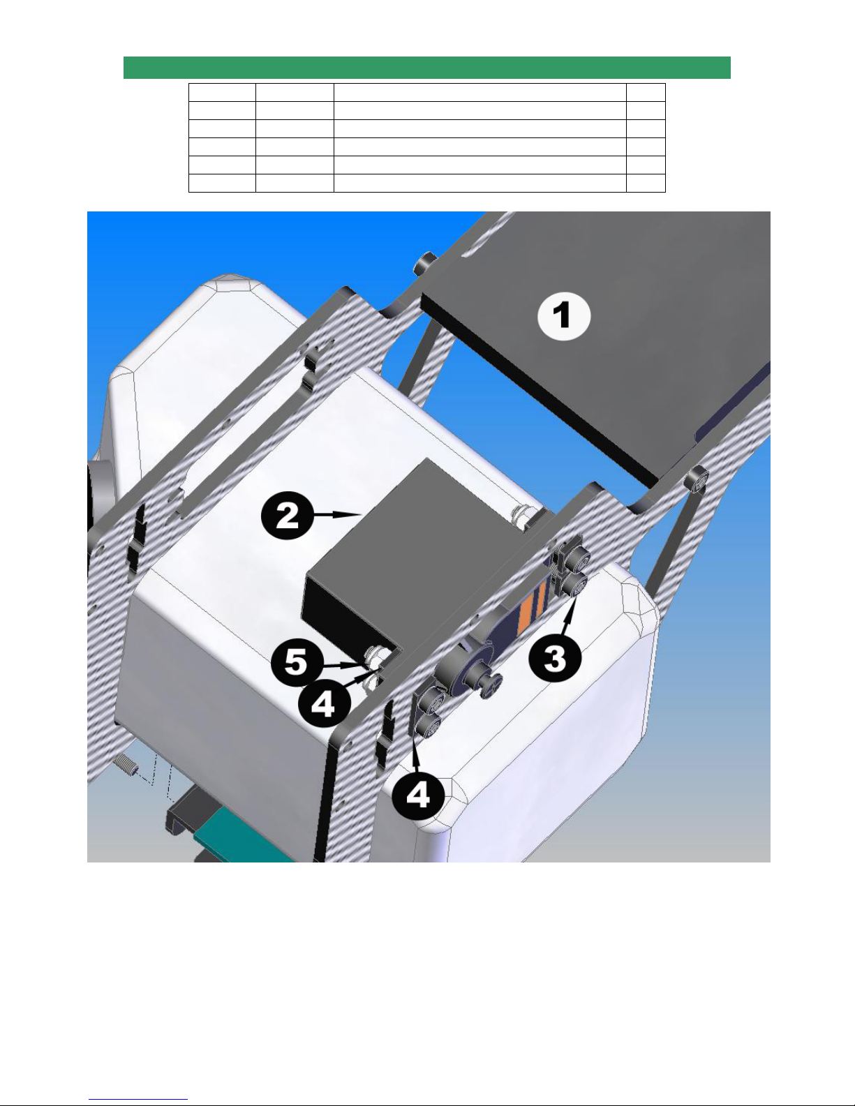
2-3 THROTTLE SERVO ASSEMBLY
No. Bag# Description Qty
1 Step 2-3 Fuel Tank Installation 1
2***** Servo 1
3 HB M2.5x14 Cap Head Bolt 4
4 2 Servo Fixing Plate 4
5 HB M2.5 Locknut 4
Note: Frame shown in the drawing may look differently
Page 33 of 85
Page 34
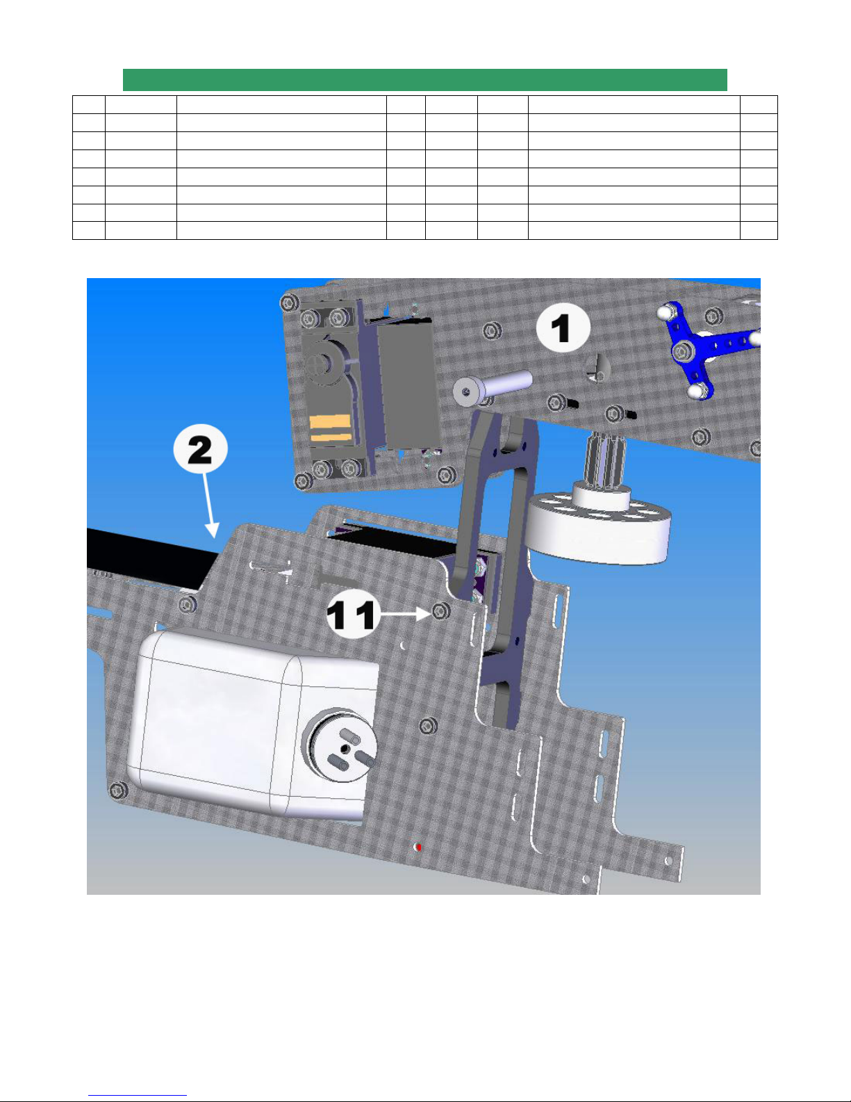
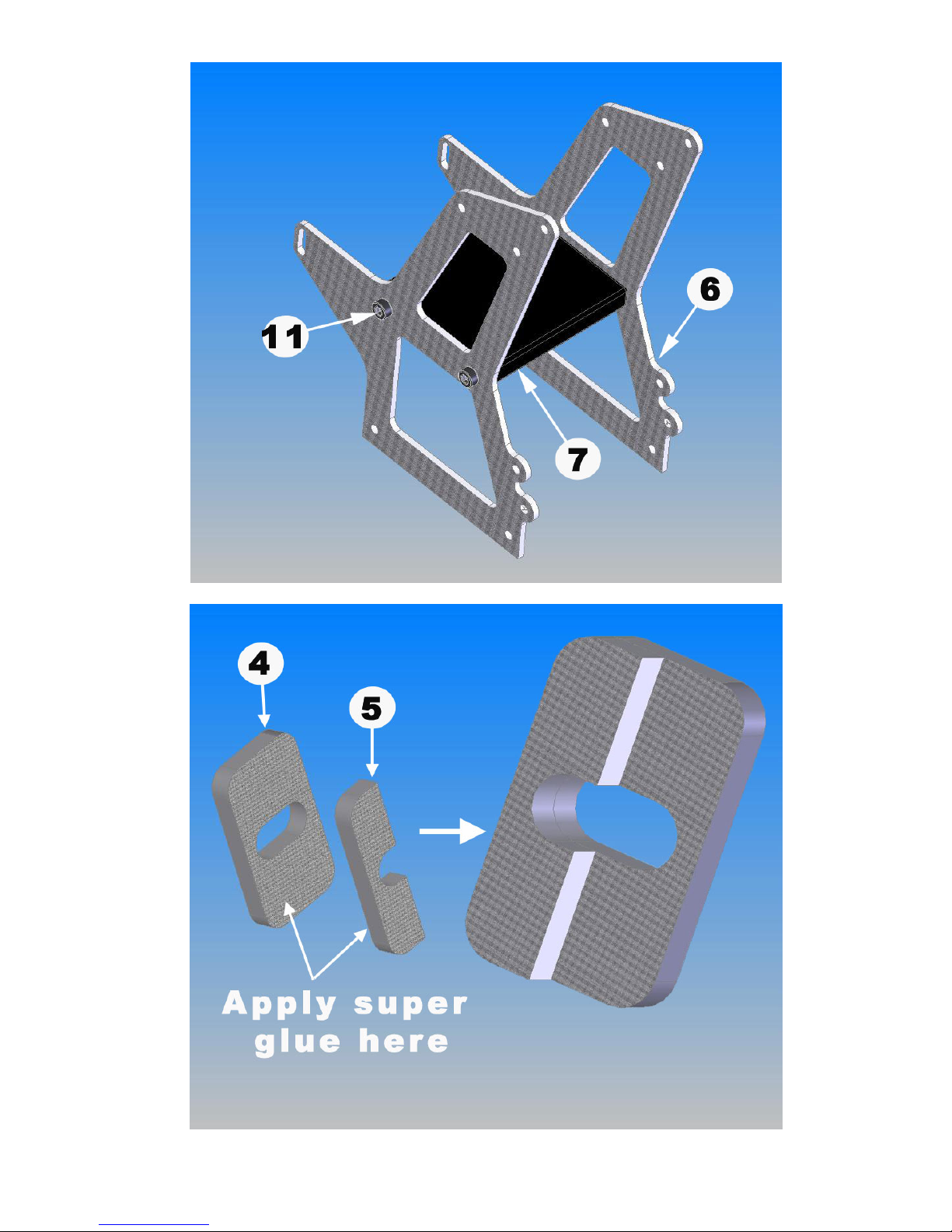
2-4 FAN SHROUD & REAR FRAME ASSEMBLY
No Bag# Description Qty No. Bag# Description Qty
1 Step 1-10 Upper Frame from step 1-10 1 8 2 26mm Inner One-Piece Rear Spacer 1
2 Step 2-3 Lower Frame from step 2-3 1 9 2 12mm Outer One-Piece Rear Spacer 2
3 In box Fan Shroud 1 10 HB 2.5x6 Self-Taping Screw 4
4 Frame Full Fan Shroud Mounting Tab* 2 11 HB M3x8 Cap Head Bolt 8
5 Frame Half Fan Shroud Mounting Tab* 2 12 HB M3x20 Cap Head Bolt 6
6 Frame Rear Frame 2 13***** Super Glue 1
7 Frame Gyro Plate 1
*For Quick Super Learner 37 only
Page 34 of 85
Page 35
Page 35 of 85
Page 36
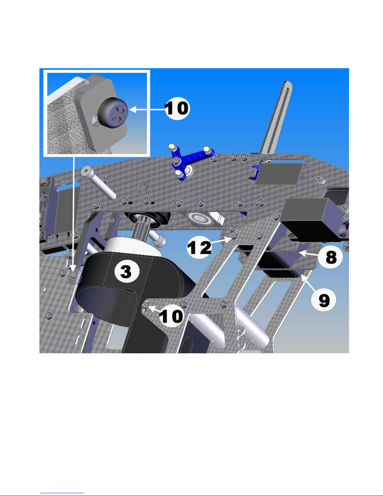
Note: Frame shown in the drawing may look differently
Page 36 of 85
Page 37
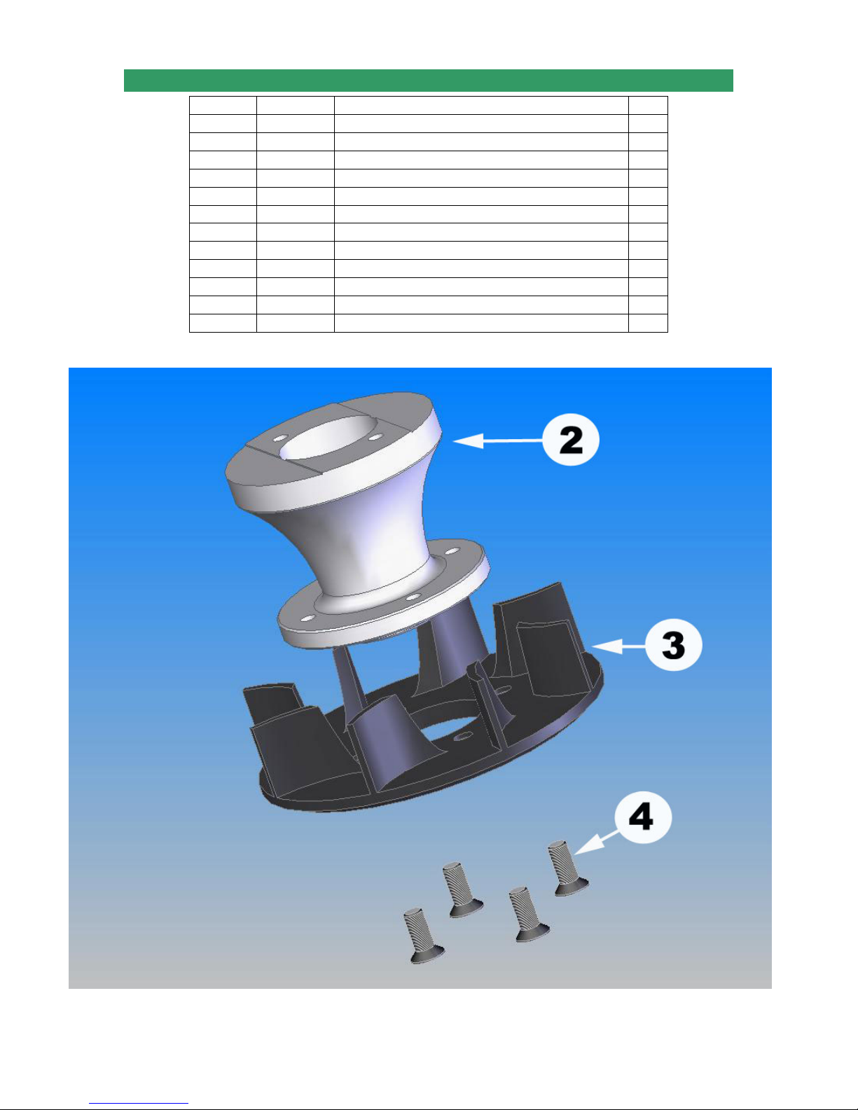
2-5 ENGINE ASSEMBLY
No. Bag# Description Qty
1***** Engine 1
2 2 Fan Hub 1
3 2 Cooling Fan 1
4 HB M3x6 Phillips Screw Flat Head 4
5 2 Engine Hub Lower Collet 1
6 HB M6 Nord-Loc Washer 2
7***** M6 Hex Nut 1
8 2 Clutch Shoe 1
9 2 Engine Mount 1
10 HB M3x12 Cap Head Bolt* 4
11 2 Engine Hub Upper Collet 1
12 HB M3x6 Cap Head Bolt 2
*Note: Model 46 takes M3.5x16 Cap Head Bolts
Page 37 of 85
Page 38
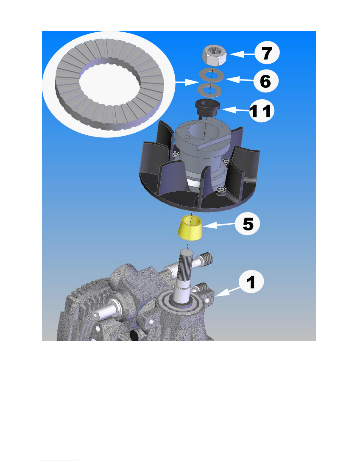
Note: Fan Hub Assy may look differently
Page 38 of 85
Page 39
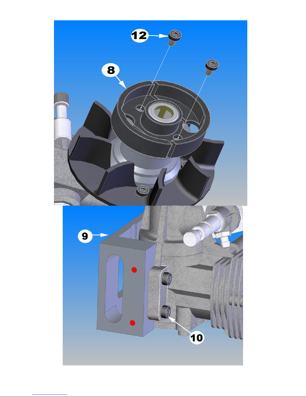
Note: Engine Mount may look differently from the one in the kit.
Page 39 of 85
Page 40
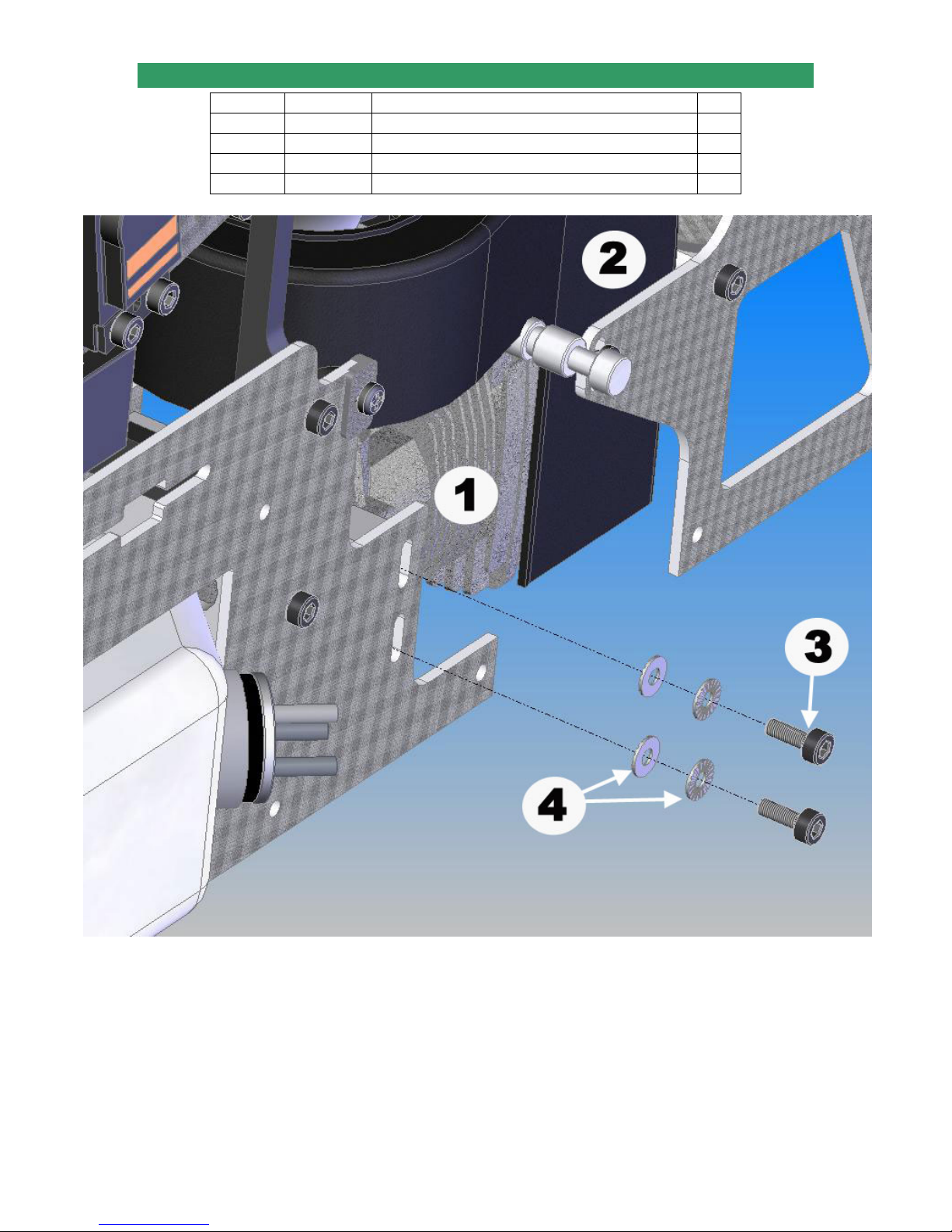
2-5 ENGINE INSTALLATION
No. Bag# Description Qty
1 Step 2-4 Engine Assembly 1
2 Step 2-3 Assembly up to step 2-3 1
3 HB M3x8 Cap Head Bolt 4
4 HB M3 Nord-Loc Washer 8
Page 40 of 85
Page 41
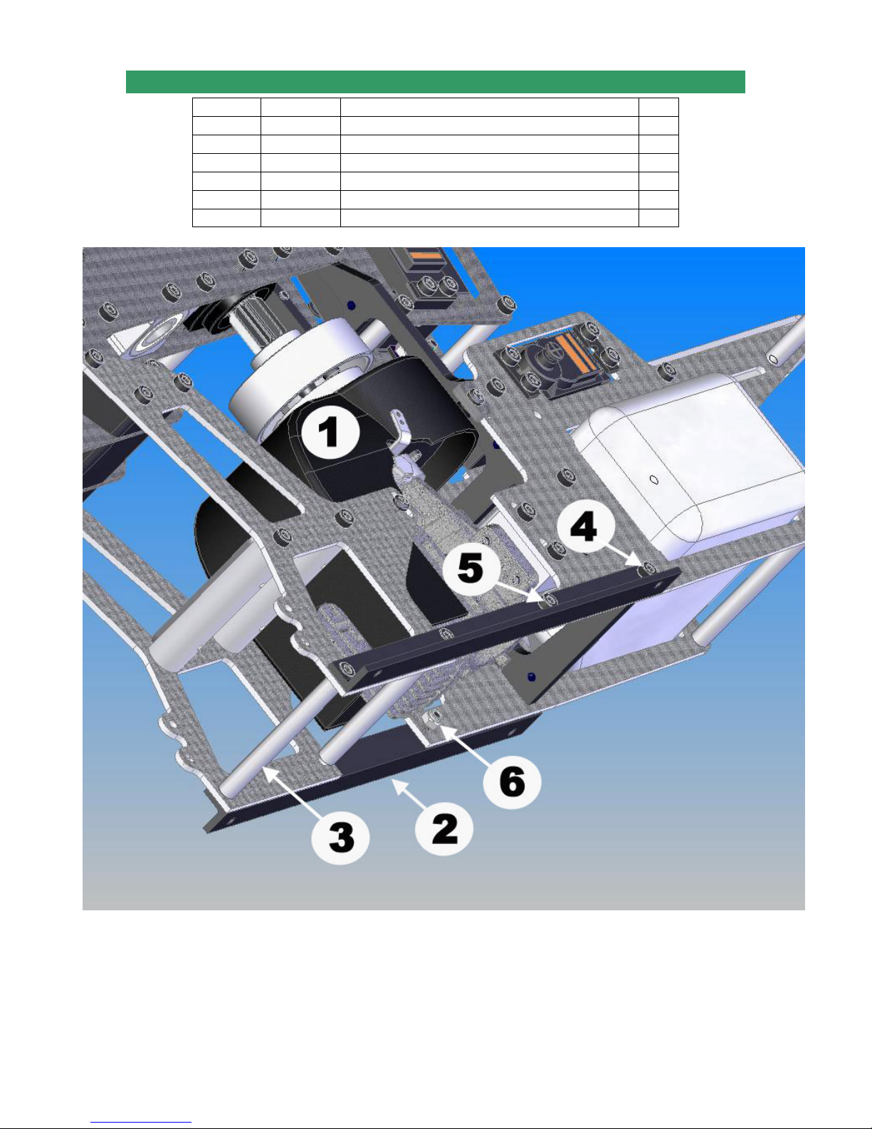
2-6 FRAME ANGLE ASSEMBLY
No. Bag# Description Qty
1 Step 2-5 Assembly up to step 2-5 1
2 Frame Frame Angle 2
3 2 M3x54 Cross Member 2
4 HB M3x8 Cap Head Bolt 6
5 HB M3x10 Cap Head Bolt 2
6 HB M3 Locknut 2
Note: Frame shown in the drawing may look differently
Page 41 of 85
Page 42
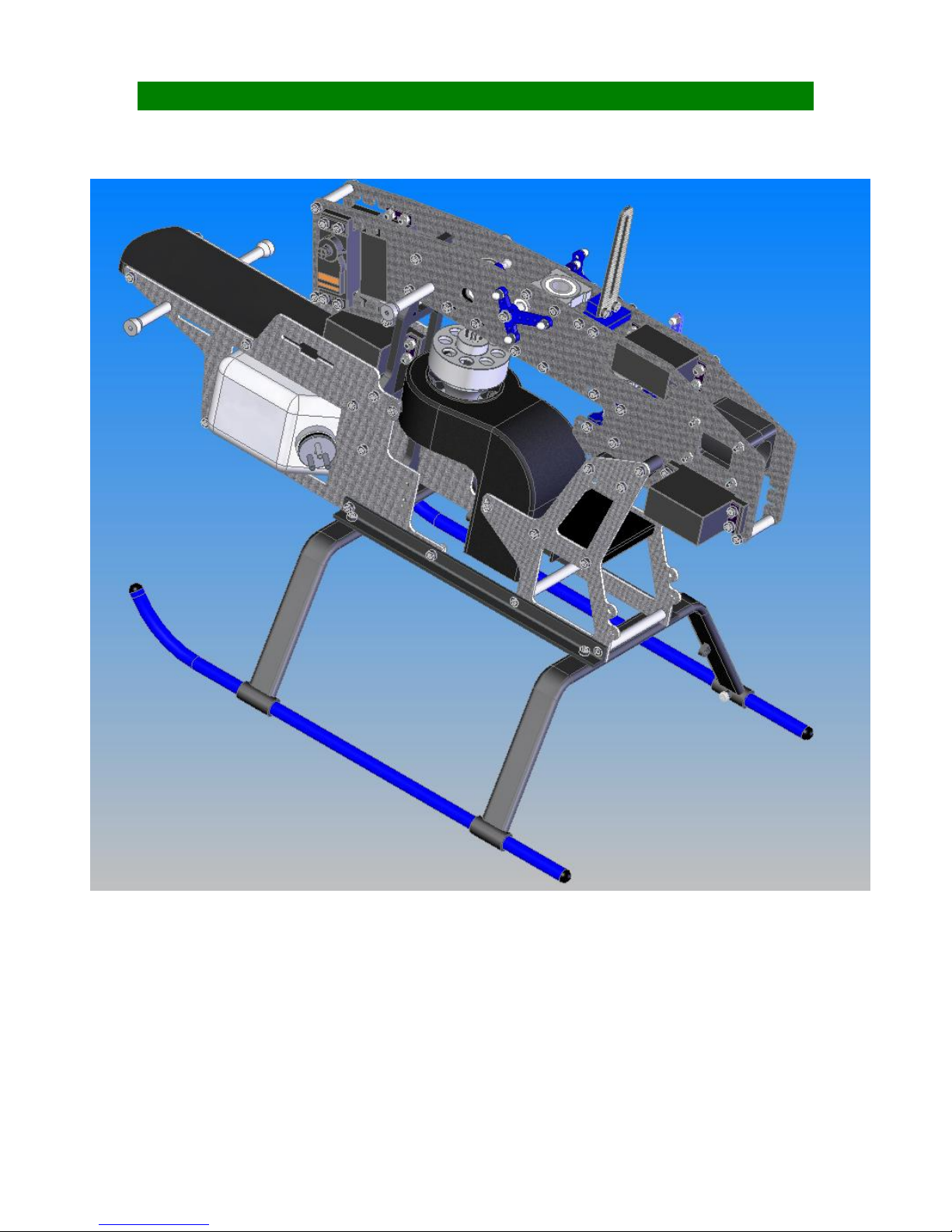
SECTION 3: LANDING GEAR ASSEMBLY Bag 3
Page 42 of 85
Page 43
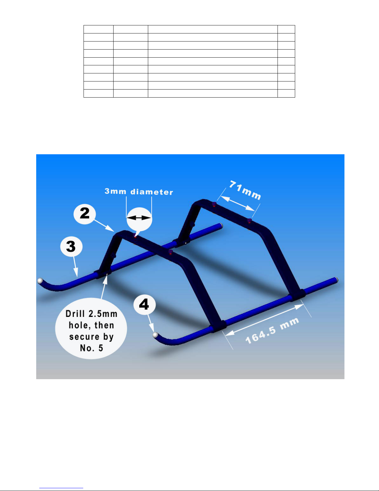
No. Bag# Description Qty
1 Step 2 Assembly up to Section 2 1
2 3 Landing Gear Strut 2
3 3 Landing Gear Skid 2
4 3 Landing Gear End Cap 4
5 HB M2.5x6 Self Taping Screws 4
6 HB M3x12 Cap Head Bolt 4
7 HB M3 Locknut 4
8***** CA Glue 1
• Drill 4 holes in the Landing Gear Struts with a 3mm drill bit with a spacing of 71mm
• Install the Landing Gear Skids into the Struts.
• Apply CA Glue into the Landing Gear End Cap then insert them into the Skids.
Drill four 2.5mm holes into the little rounds on the ends of the Struts then secure them with the
four M2.5x6 Phillips Screws.
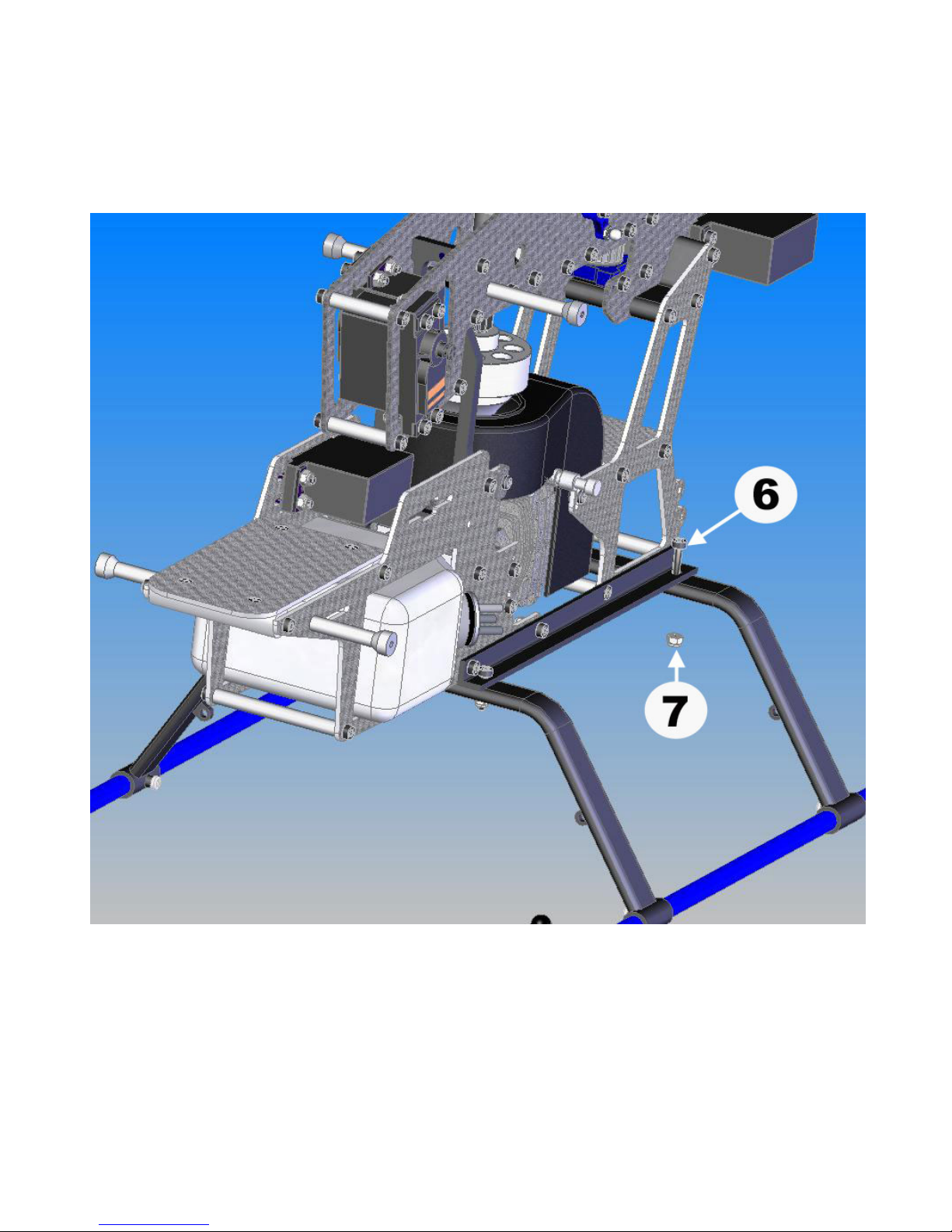
• Install the Main Frames onto the Landing Gear Assembly and secure them with
four M3x14 Cap Head Bolts.
Note: It is recommended to use “Landing Gear Dampener” to reduce vibration. See
“Other Hardware & Optional Accessories” to make order. Landing Gear Dampener is
installed between the Landing Gear and the Landing Supports.
Page 43 of 85
Page 44
Page 44 of 85
Page 45
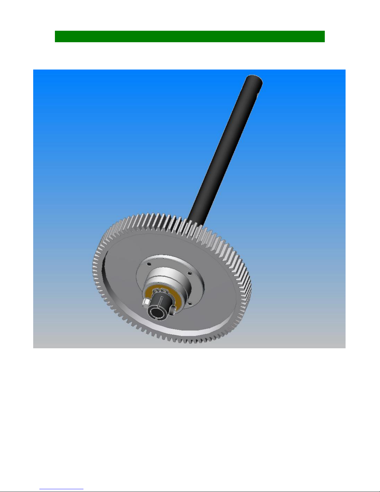
SECTION 4: DRIVING SYSTEM Bag 4
Page 45 of 85
Page 46
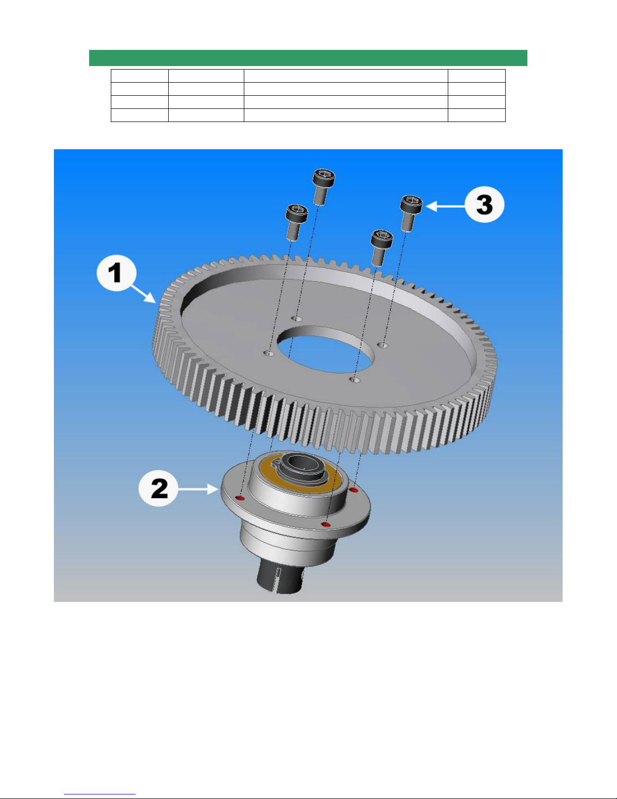
4-1 MAIN GEAR ASSEMBLY
No. Bag# Description Qty
1 4
2 4 Auto-rotation Clutch 1
3 HB M3x6 Cap Head Bolt 4
Main Gear 1
Page 46 of 85
Page 47
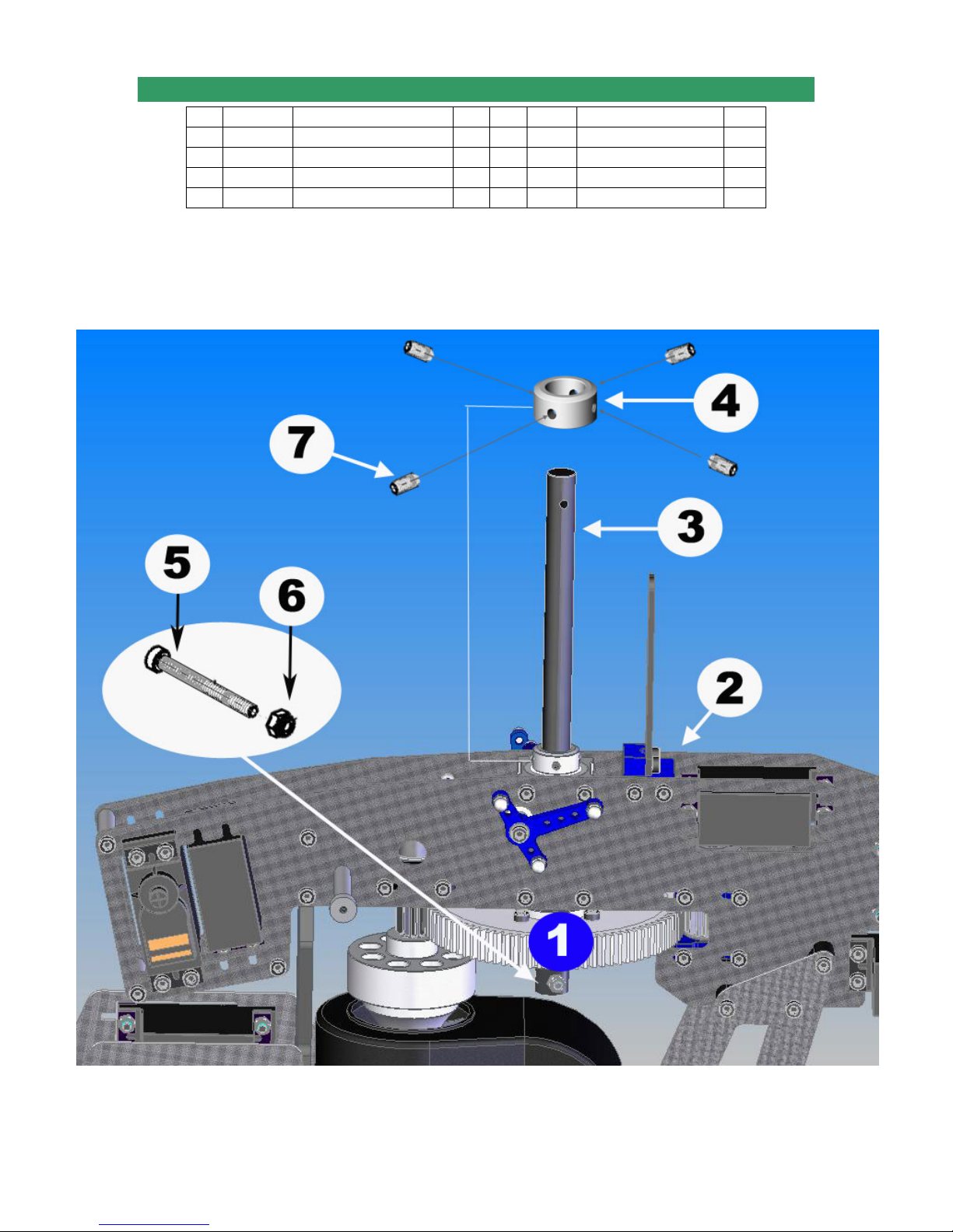
4-2 MAIN GEAR INSTALLATION
No. Bag# Description Qty No. Bag# Description Qty
1 Step 4-1
2 Step 3 Assembly up to step 3 1 6 HB M3 Locknut 1
3 3 Main Shaft 1 7 HB M3X5 Set Screw 4
4 3 Main Shaft Collar 1
• Slide the Main Gear Assembly in; install the Main Shaft down, then secure with one
M3x16 Cap Head Bolt and one M3 Locknut.
• Install the Main Shaft Collar on the Main Shaft then secure with four M3x5 Set
Screws. Be sure the ridge goes down.
Main Gear Assembly 1 5 HB M3x16 Cap Head Bolt 1
Page 47 of 85
Page 48
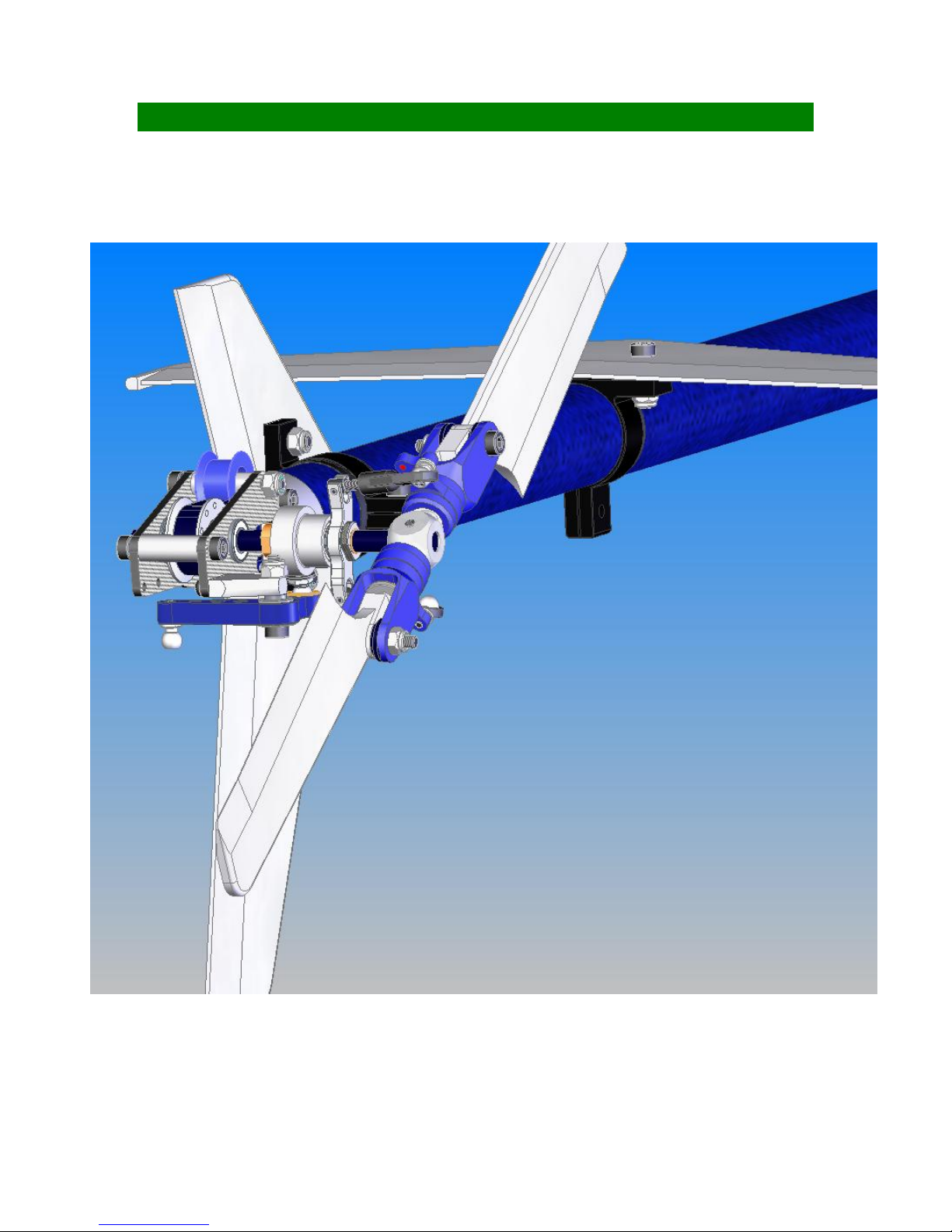
SECTION 5: TAIL ASSEMBLY Bag 5
Tail Rotor shown may look differently.
Page 48 of 85
Page 49
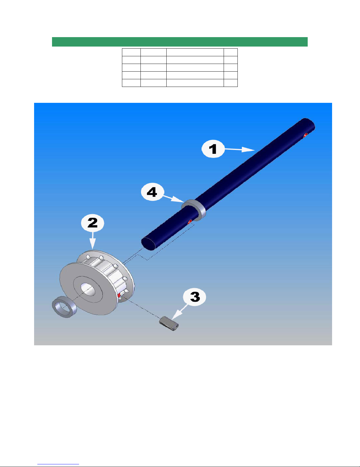
5-1 TAIL PULLEY GEAR ASSEMBLY
No. Bag# Description Qty
1 5
2 5 Tail Pulley Gear 1
3 HB M3x5 Set Screw 1
4 5 M5x7x2 Spacer 2
Tail Output Shaft 1
Page 49 of 85
Page 50
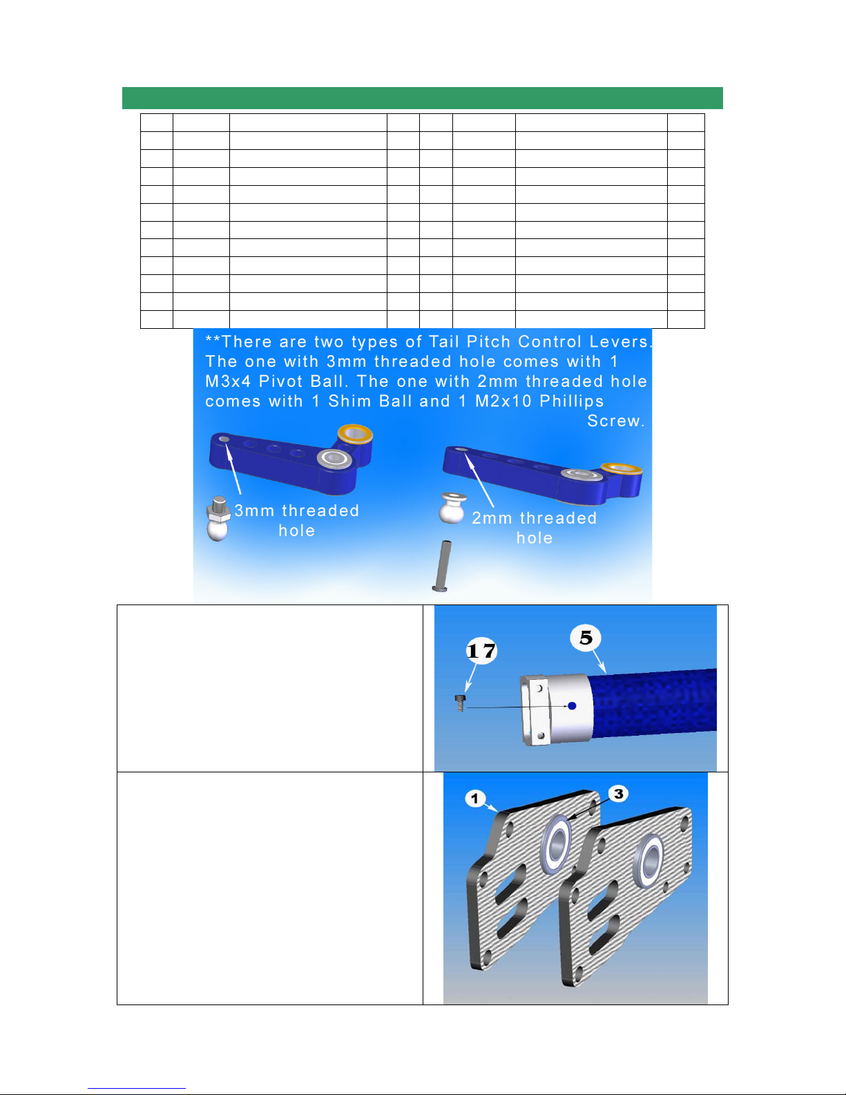
5-2 TAIL ROTOR ASSEMBLY
No Bag# Description Qty No. Bag# Description Qty
Frame Tail Case Side Plate 2 12 5 Tail Pitch Control Lever 1
1
2 5 Tail Pitch Lever Mount 1 13 HB M3x5x1 Spacer 1
3 5 5X10X4Flange Bearing 2 14 HB M3x16 Cap Head Bolt 1
4 HB M2x6 Phillips Screw 2 15 HB M3 Locknut 2
5 In box Tail Boom (in Box) 1 16 Step 5-1 Tail Pulley Gear Subassy 1
6 In box Timing Belt (in Box) 1 17 HB M2.5x6 Cap Head Bolt 1
7 HB M3x6 Cap Head Bolt 6 18 HB M3x7 Flat Washer 1
8
9 HB M3x4 Pivot Ball Stud** 2 20 5 Tail Idler 1
10 5 M2.3 Medium Ball Link 2 21 5 3x6x5.5 Spacer 2
11
5 Tail Case Cross Member 1
Tail Pitch Slider 1
5
19 HB M3x25 Cap Head Bolt 1
First, to prevent the Boom End from
rotating, drill a 2.5mm hole in the side of
the Boom End, then secure with an M2.5x6
Cap Head Bolt.
Install the Bearings into the Tail Case Side
Plates. The flanges should be inside.
Sometimes, the holes are too tight; you
have to sand them a little bit.
Page 50 of 85
Page 51
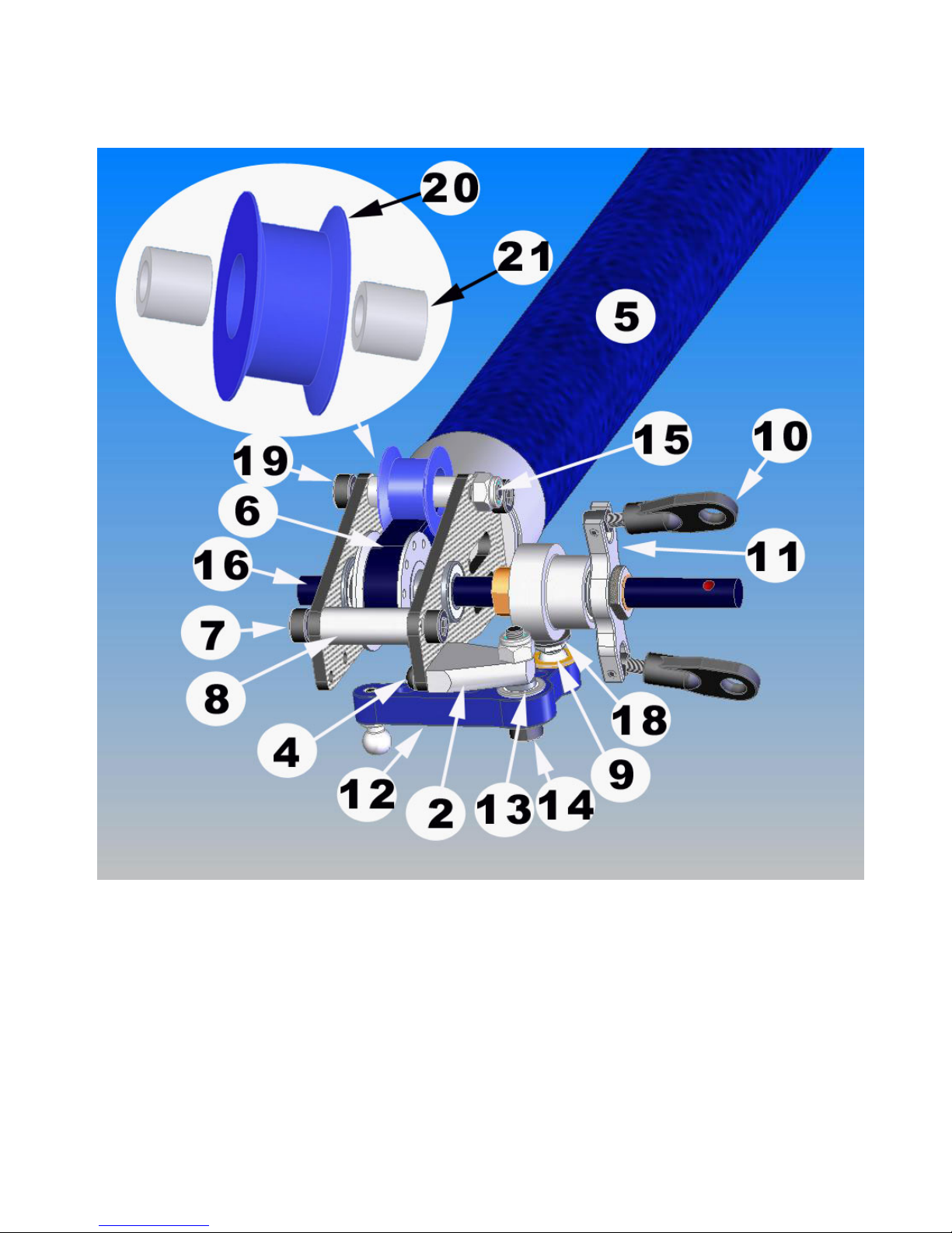
Note: Normally you just need one M3x5x1 Spacer between the Tail Pitch Control Lever
and Tail Pitch Lever Mount but you may need two of them in some cases (if you do not
have enough clearance for the lever.)
Page 51 of 85
Page 52
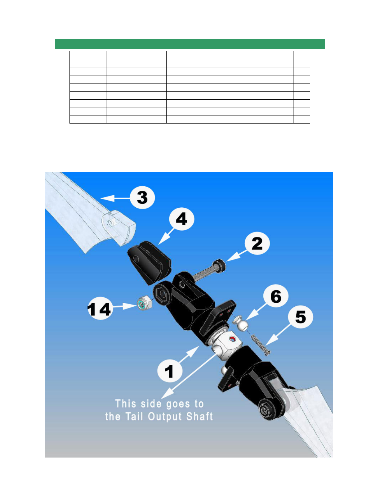
5-3 TAIL ROTOR INSTALLATION
No. Bag# Description Qty No. Bag# Description Qty
1 5 Dual Bearing Tail Rotor 1 9 5 Horizontal Fin Mount 1
2 HB M3x22 Cap Head Bolt 2 10 5 Vertical Fin Mount A * 1
3 5 Tail Blade 2 11 5 Vertical Fin Mount B* 1
4 5 Tail Blade Spacer 4 12 5 Horizontal Fin** 1
5 HB M2x8 Phillips Screw 2 13 5 Vertical Fin** 1
6 HB Shim Ball 2 14 HB M3 Locknut 4
7 HB M3x6 Cap Head Bolt 2 15 HB M3x30 Cap Head Bolt 2
8 HB M3x5 Set Screw 1 16 Step 5-2 Tail Rotor Assembly 1
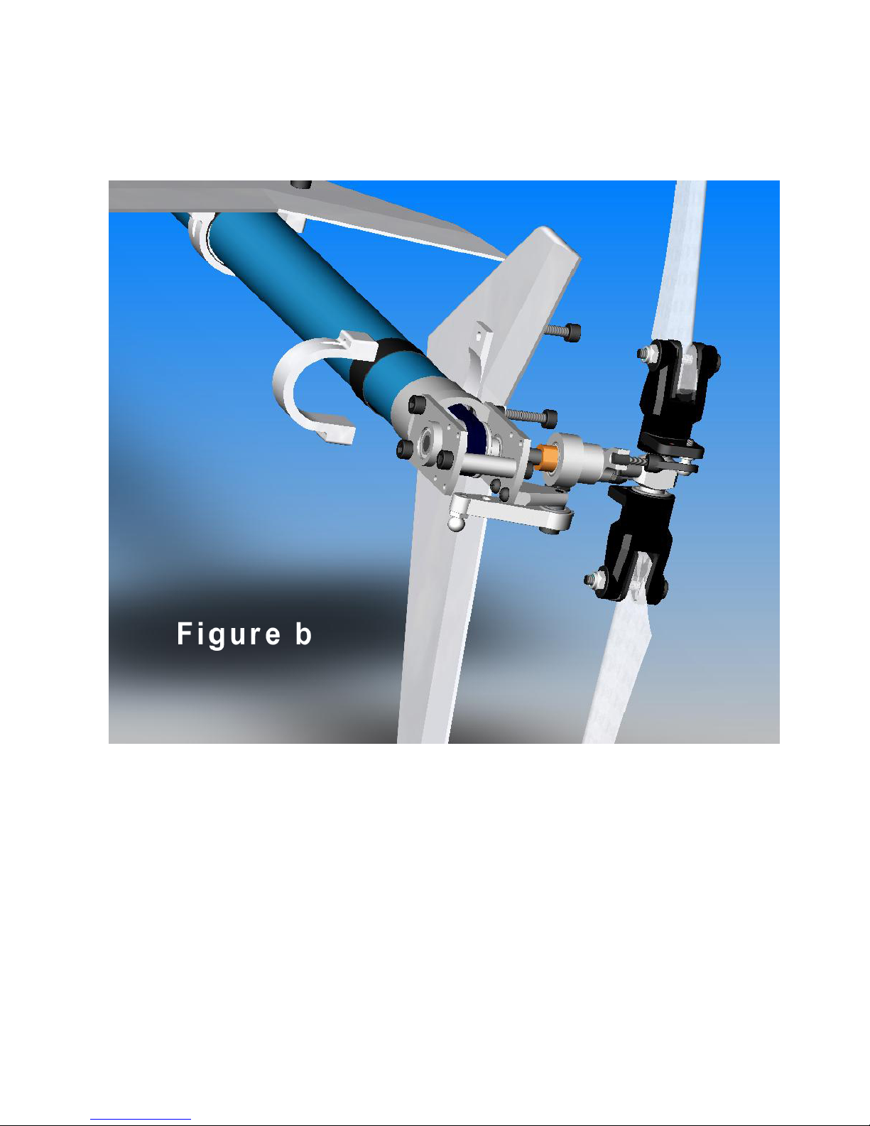
*Sometimes for the Vertical Fin Set, you may have one piece of Vertical Fin Mount and
one Vertical Fin molded with other mount. It works same as the other but the way you
install is a little bit different (see figure b). The Cap Head Bolt for this version should be
M3x12; the Locknuts are not needed.
*
* Carbon Fin Set is also available for option.
Page 52 of 85
Page 53
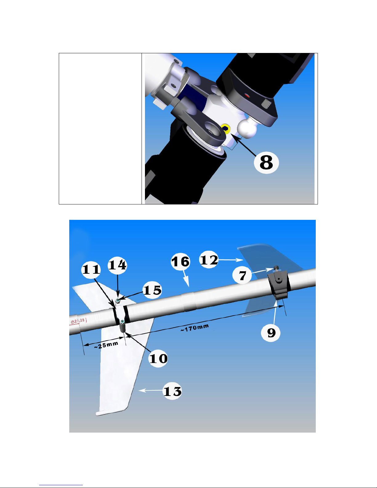
After installing all the
parts as shown above,
slide this subassembly
on the output shaft then
secure it with one M3x5
Set Screw.
Wrap electric tape around the boom couple times where you are going to install the fin
mounts. Note: Fin set may look lightly differently from the one in the kit.
Page 53 of 85
Page 54
OR
Page 54 of 85
Page 55
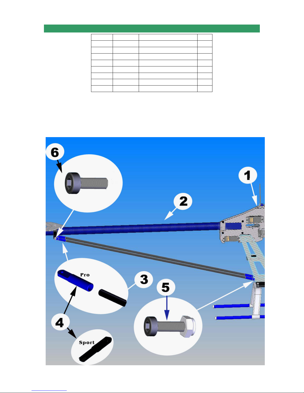
5-4 TAIL INSTALLATION
No. Bag# Description Qt.
1
2 Step 5-3 Tail Assembly 1
3 In box Boom Support 2
4 5 Boom Support End 4
5 HB M3x12 Cap Head Bolt 2
6 HB M3x8 Cap Head Bolt 2
7 HB M3 Locknut 2
8***** CA Glue 1
• Note for installing the timing belt: Turn the Tail assembly so that the Tail Output Shaft
pointing upward put the belt onto the Transmission, then twist the Tail Assembly 90
to the right. Make sure the belt not too tight or loose. Tighten the four screws on the
boom holders.
• Measure the Boom Support carefully before cutting. It is a good idea if you install one
end of the rod first, then make a measurement on the other and cut it. Remember
apply CA Glue for the rods when installing into the Support Ends.
Step 4 Assembly up to step 4 1
o
Page 55 of 85
Page 56
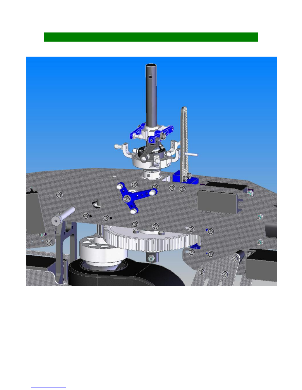
SECTION 6: CONTROL SYSTEMS Bag 6
Page 56 of 85
Page 57
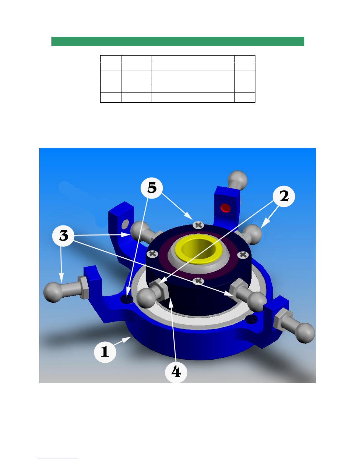
6-1 SWASHPLATE ASSEMBLY
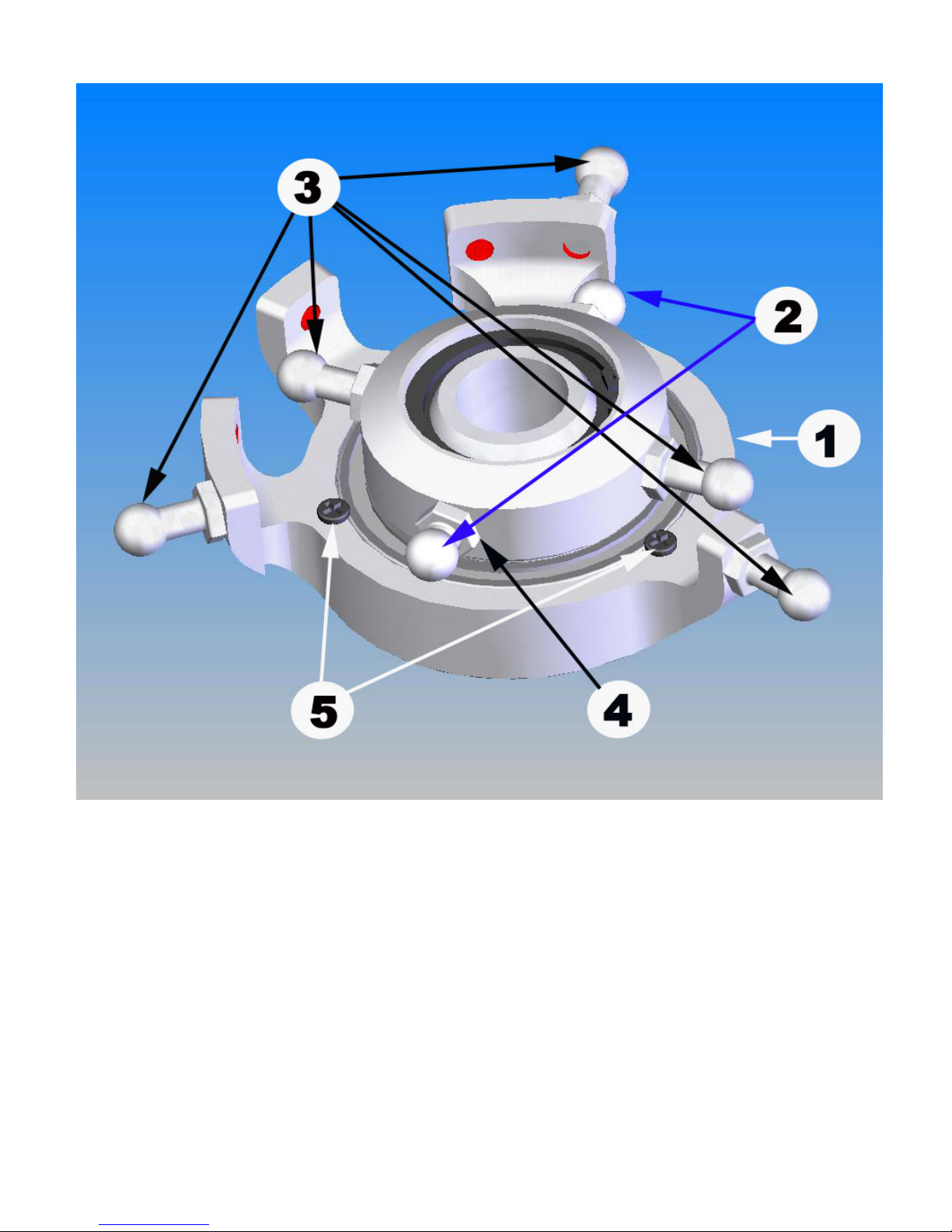
Note: There are some kinds of the Swashplate. One has little holes (maybe 7, 4, or 3 of
them.) The others have no hole on it. Both work the same. If you got the one with holes,
just fill them in with Phillips Screws. If you got the one with no hole, do not worry about
Phillips Screws; the Swashplate still works well.
No. Bag# Description Qty
1 6
2 HB M3x4 Pivot Ball Stud 2
3 HB M3x7 Pivot Ball Stud 5
4 HB
5 HB
Swashplate Complete 1
M3 x7 Flat Washer
M2X4 Phillips Screws
4
7
Page 57 of 85
Page 58
Page 58 of 85
Page 59
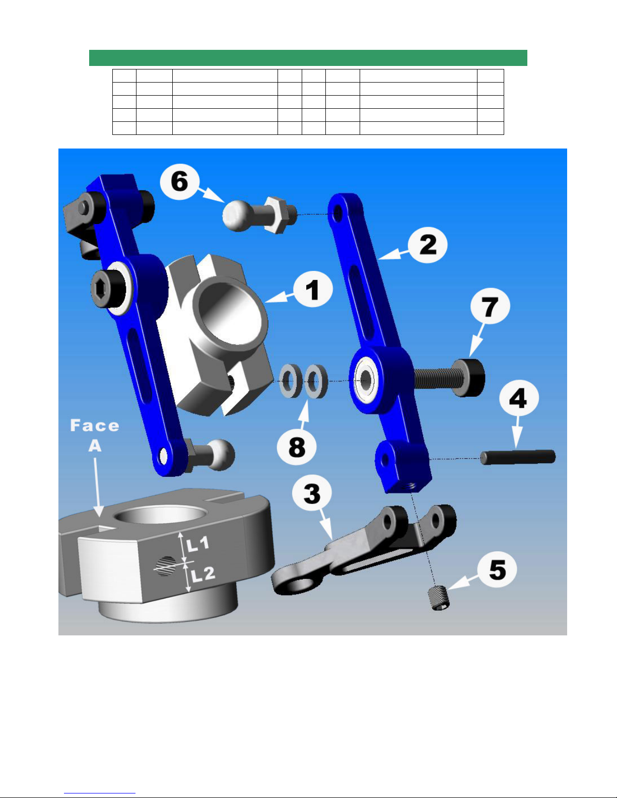
6-2 WASHOUT ASSEMBLY
No. Bag# Description Qty No. Bag# Description Qty
1 6
2
6
3
6
4
6
Washout Base 1 5 HB
Washout Arm 2 6 HB M3x7Pivot Ball Stud 2
Washout Link 2 7 HB M3x12 Cap Head Bolt 2
Washout Link Pin 2 8 HB M3X5X1 Spacer 4
M3x5 Set Screw
2
Note: There are some versions of the Washout Base (Item No. 1). All of them work the
same but they should be installed appropriately:
• If L1 is shorter or equal to L2, face A should go up.
• If L1 is longer than L2, face A should go down.
Page 59 of 85
Page 60
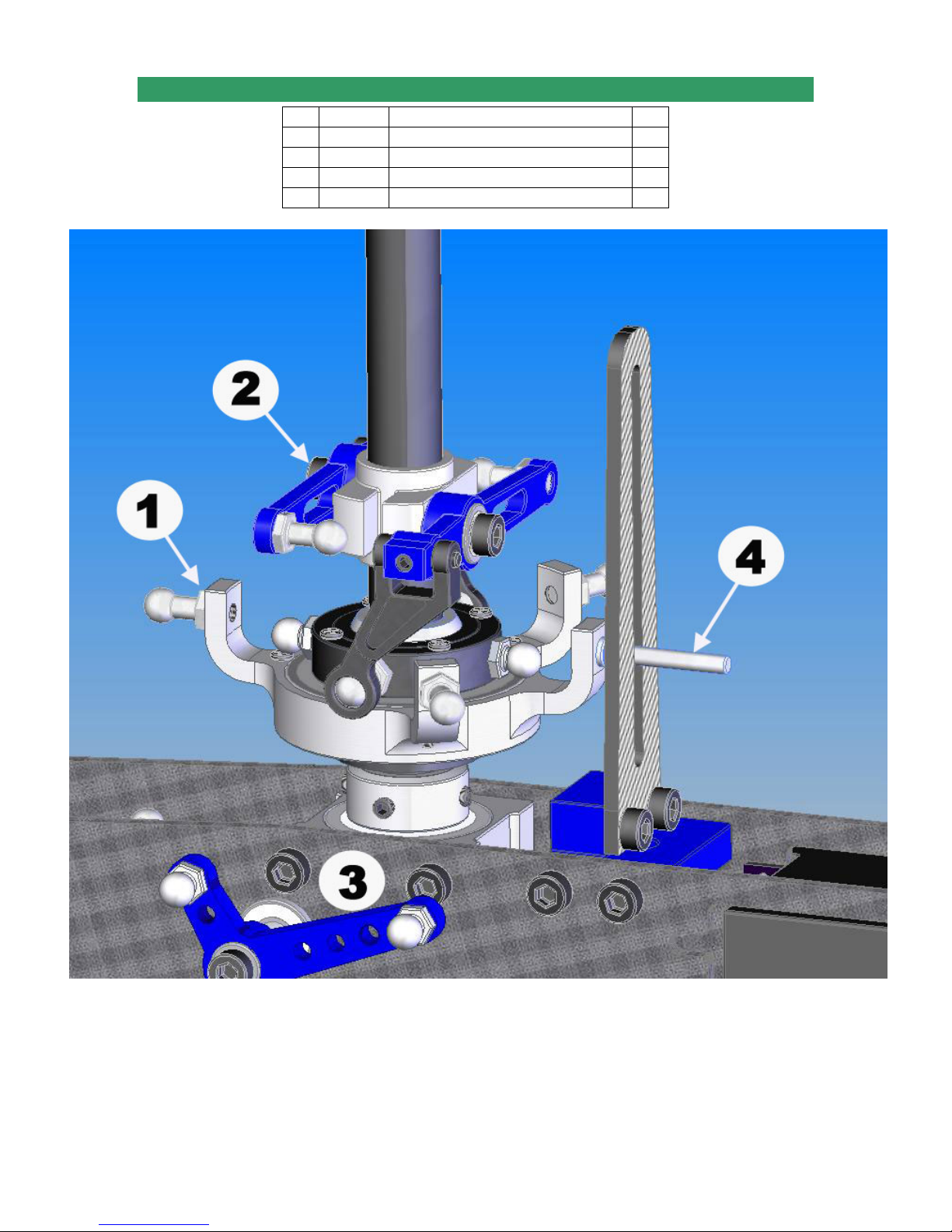
6-3 CONTROL SYSTEM INSTALLATION
No. Bag# Description Qty
1 Sep 6-1
2
Step 6-2
3
Step 5
4 6 Swash Anti-rotation Pin 1
Swashplate Assembly 1
Washout Assembly 1
Assembly up to step 5 1
Page 60 of 85
Page 61
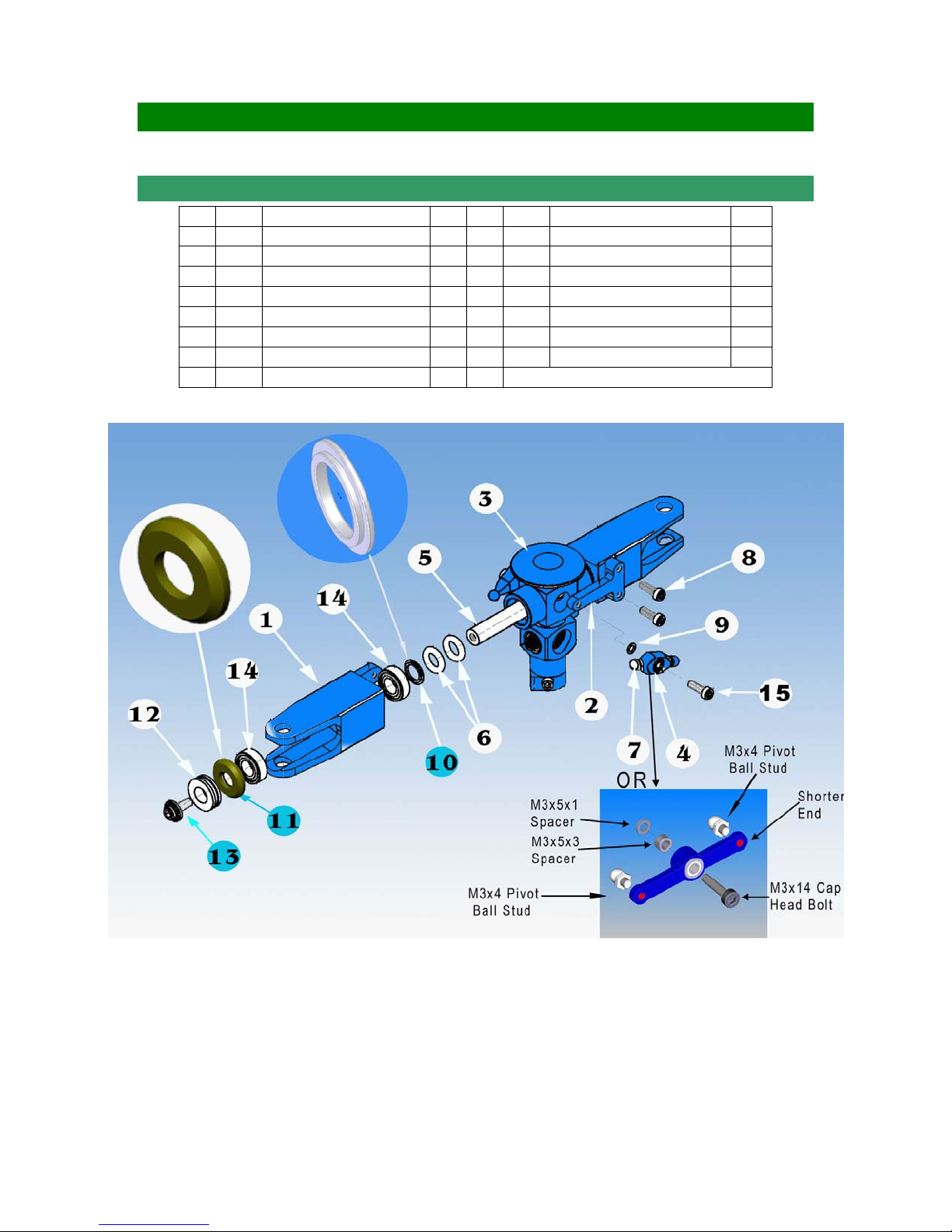
SECTION 7: ROTOR HEAD Bag 7
7-1 MAIN ROTOR HUB ASSEMBLY
No. Bag# Description Qty No. Bag# Description Qty
1 7
2
3 7 Center Hub 1 11 7 Thrust Bearing Spacer 2
4
5 7 Head Spindle 1 13 7 M4 x8 Flange Cap Head Bolt 2
6 7 Dampener O-Ring 4
7 HB M3x7 Pivot Ball Stud(1) 2
8 HB M3x10 Cap Head Bolt** 4 *Sport version: plastic
Main Blade Grip* 2 9 HB M3X5X3 Spacer 2
Pitch Arm** 2 10 7 Head Spindle Spacer 2
7
7 Hiller Arm
**Sport version: Pitch Arms is built in the Main Blade Grips so there is no M3x10 Cap Head Bolts
(1) or four M3x4 Pivot Ball Studs; (2) or two M3x14 Cap Head Bolts
2 12 7 8x16x5 Thrust Bearing 2
14
7 8x16x5 Regular Bearing 4
15
HB M3x12 Cap Head Bolt(2) 2
Note: Some Center Hubs are designed for one O-ring each side. If this is your case, use
one O-ring each side. The beveled edge of the Thrust Bearing Spacer (No. 11) should
be face away from the Center Hub. The flanges of the bearings of the Hiller Arms should
face outside. Usually the Thrust Bearing has three parts: two race washers and caged
ball bearings. The caged ball bearings will be between two race washers. In some cases,
you may get different version of the Thrust Bearing: one race washer, one flat washer,
and caged ball bearings in your kit. That is fine; it still works the same. In this case, you
need to install the flat washer first (next to Thrust Bearing Spacer-No. 11), then the
caged ball bearings, the race washer goes last.
Page 61 of 85
Page 62
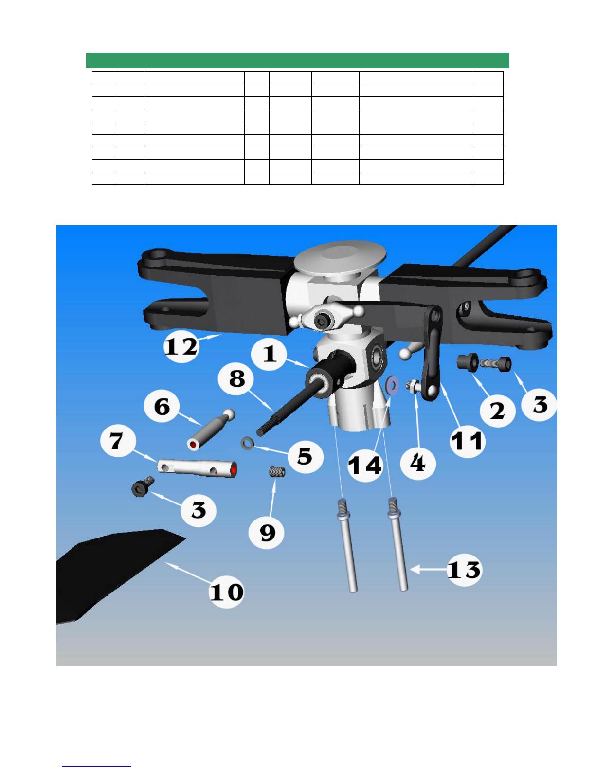
7-2 FLYBAR & SEESAW ASSEMBLY
No. Bag# Description Qty No. Bag# Description Qty
1 7
2
3 HB M3x8 Cap Head Bolt 4 11
4 HB M3x7 Pivot Ball Stud 2 12
5 HB M3x5x1 Spacer 2 13
6 7 Fly-Bar Control Arm A 2 14
7 7 Fly-Bar Control Arm B 2 15****
8 In 3mm Standard Flybar 1
Seesaw 1 9 HB
Seesaw Collar 2 10
7
M4X4 Set Screw
7 3mm Fly-Bar Paddle
7 Double Link
Step 7-1
7
HB
Main Rotor Hub Assembly 1
Washout Anti-rotation Pin 2
M3x7 Flat Washer 2
Epoxy Glue/JP Weld 1
Make sure to apply Epoxy Glue/JP Weld to the thread on Flybar and the Flybar Paddle (after
you finish the Setup)
2
2
2
Note: The Center Hub and Flybar Control Arm shown may look differently from the ones
in the kit. Attach the Double Link to the built-in ball of the Hiller Arm and the Pivot Ball
installed on the Seesaw (see drawing).
Page 62 of 85
Page 63
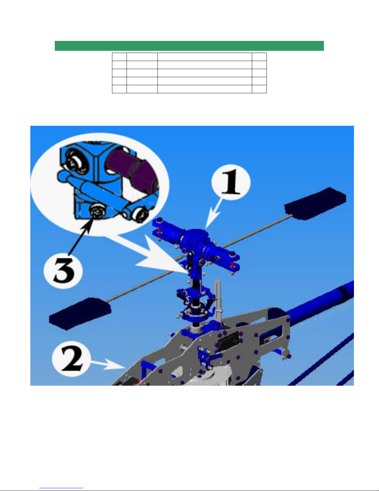
7-3 ROTOR HEAD INSTALLATION
No. Bag# Description Qty
1 Step 7-2
2 Step 6-3
3 HB M3x20 Cap Head Bolt 1
4 HB M3 Locknut 1
Install the Head Assembly into the Main Shaft, and then secure it by one M3x20 Cap
Head Bolt and one M3 Locknut.
Completed Rotor Head (step 7-2) 1
Helicopter (up to step 6-3) 1
Note: Frame may look differently.
Page 63 of 85
Page 64
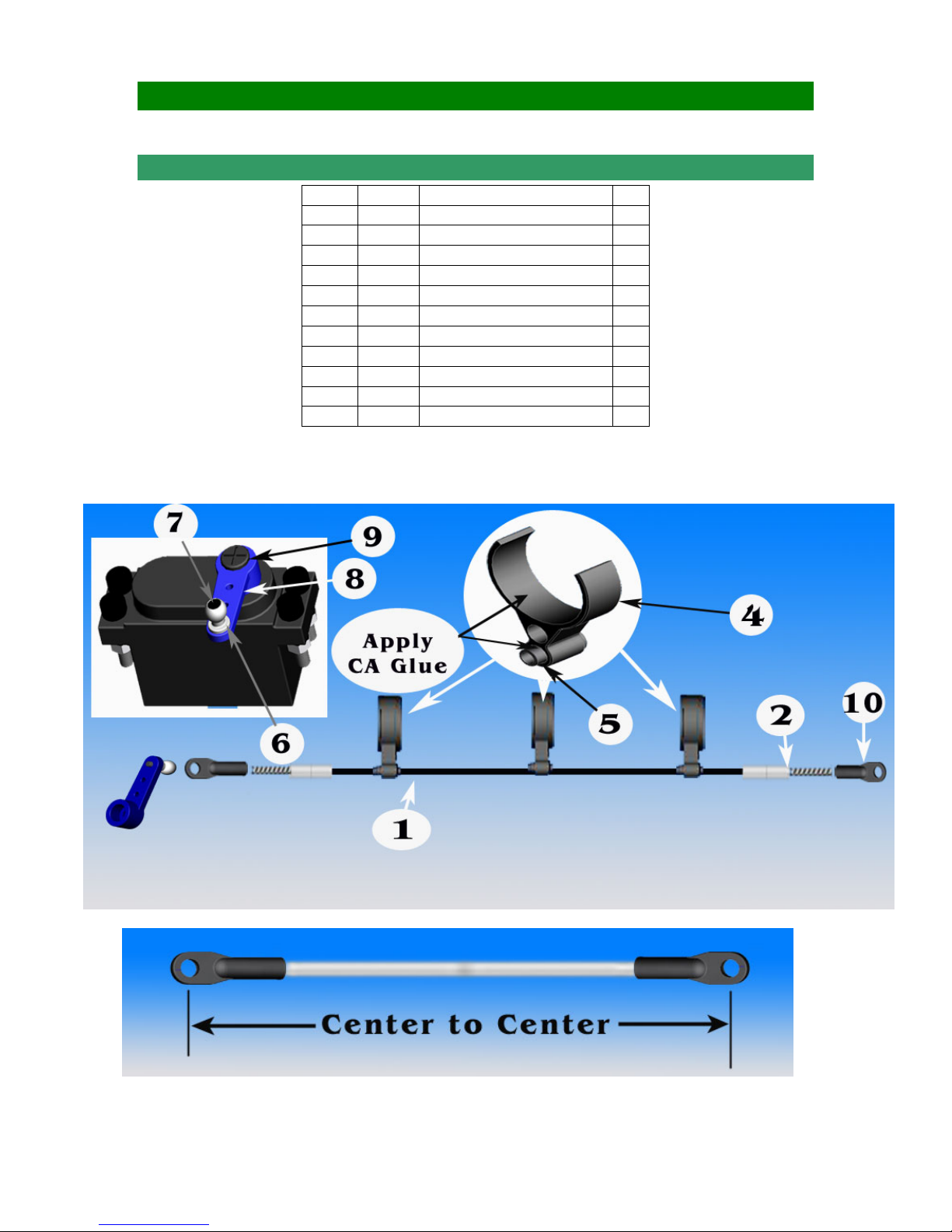
SECTION 8: LINKAGE RODS & SETTINGS Bag 8
8-1 RUDDER PUSH ROD ASSEMBLY
No. Bag# Description Qty
1
2 8 Rudder Push Rod End 2
3***** CA Glue 1
4 8 Rudder Pushrod Guide 3
5 8 Rudder Pushrod Guide Insert 3
6 8 Shim Ball 1
7 HB M2x8 Phillips Screw 1
8***** Servo Arm 1
9***** M3 Servo Phillips Screw 1
10
11*****
Note: Put electric tape around the Boom before installing the Rudder Push Guide in, so
you can remove them later when needed.
In box Rudder Push Rod 1
2.3mm Long Ball End 2
8
Electric Tape 1
The length of the Rudder Rod measured from center to center should be around 605 mm.
Page 64 of 85
Page 65
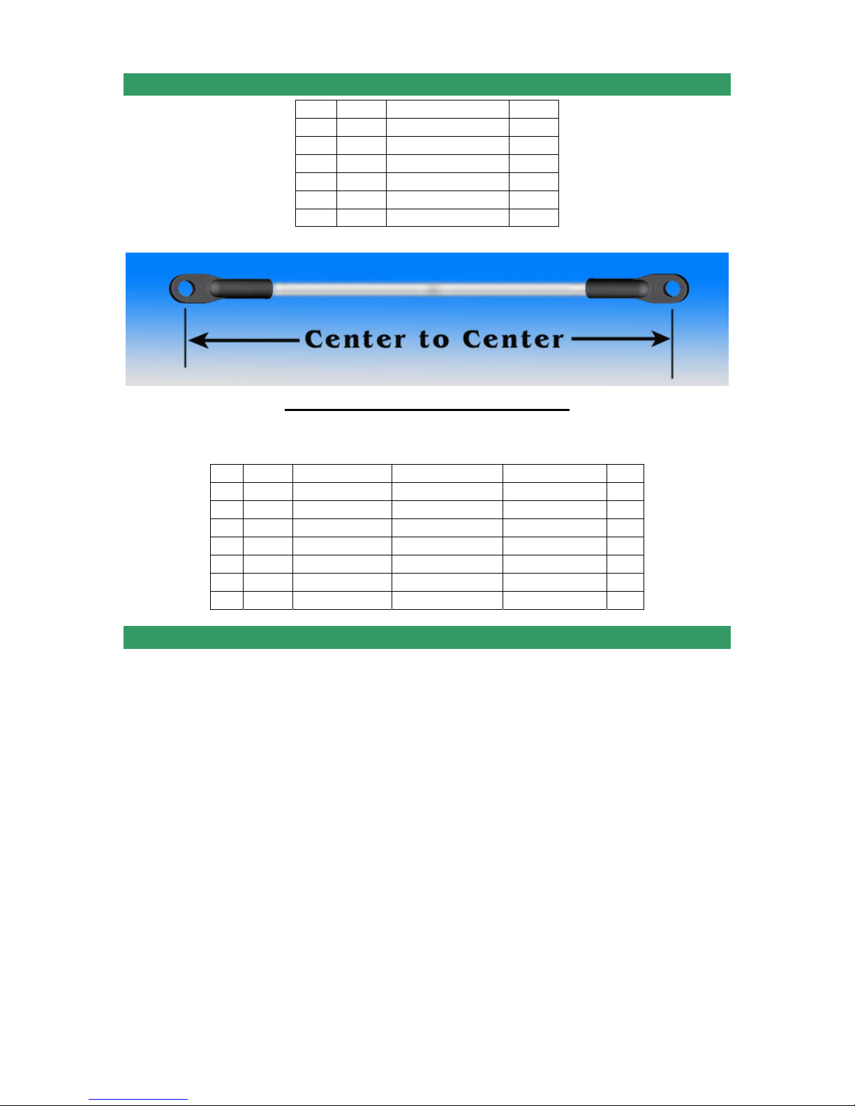
8-2 LINKAGE ROD ASSEMBLY
No. Bag# Description Qty
1 8
2
3
4
5
6
2.3 Long Ball End 19
2.3 Medium Ball End 9
8
2.3x16mm Rod 5
8
2.3x70mm Rod 4
8
2.3x75mm Rod 3
8
2.3x100mm Rod 2
8
Coding the Rod Assembly:
All the Linkages should be assembled with dimensions measured center to center and
coded as following:
No. Code Rod Description Center to Center Ball Ends Used Qty
1
2
3
4
5
6
7
2.3x16mm Rod 42 mm Medium + Long 2
A
2.3x16mm Rod 44 mm Medium + Long 3
B
2.3x70mm Rod 86 mm Medium 2
C
2.3x70mm Rod 92 mm Long 2
D
2.3x75mm Rod 103 mm Long 1
E
2.3x75mm Rod 105mm Long 2
F
2.3x100mm Rod 128 mm Long 2
G
Page 65 of 85
Page 66
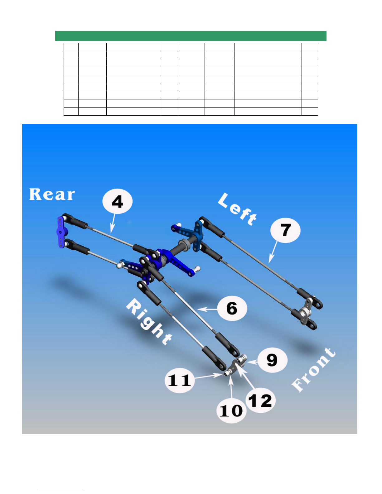
8-3 LINKAGE INSTALLATION
No. Code Center to Center Qty No. Bag# Description Qty
1
2
3
4
5
6
7
A
B
C
D
E
F
G
42 mm 2 8
44 mm 3 9*****
86 mm 2 10 HB Shim Ball 8
92 mm 2 11 HB M2x8 Phillips Screw 8
103 mm 1 12***** M3 Servo Phillips Screw 4
105 mm 2 13***** Throttle Extension 1
128 mm 2 14***** M2.5x10 Cap Head Bolt 1
15***** Single Servo Arm 1
7-3
Helicopter (up to step 7) 1
Double Servo Arm 3
Page 66 of 85
Page 67
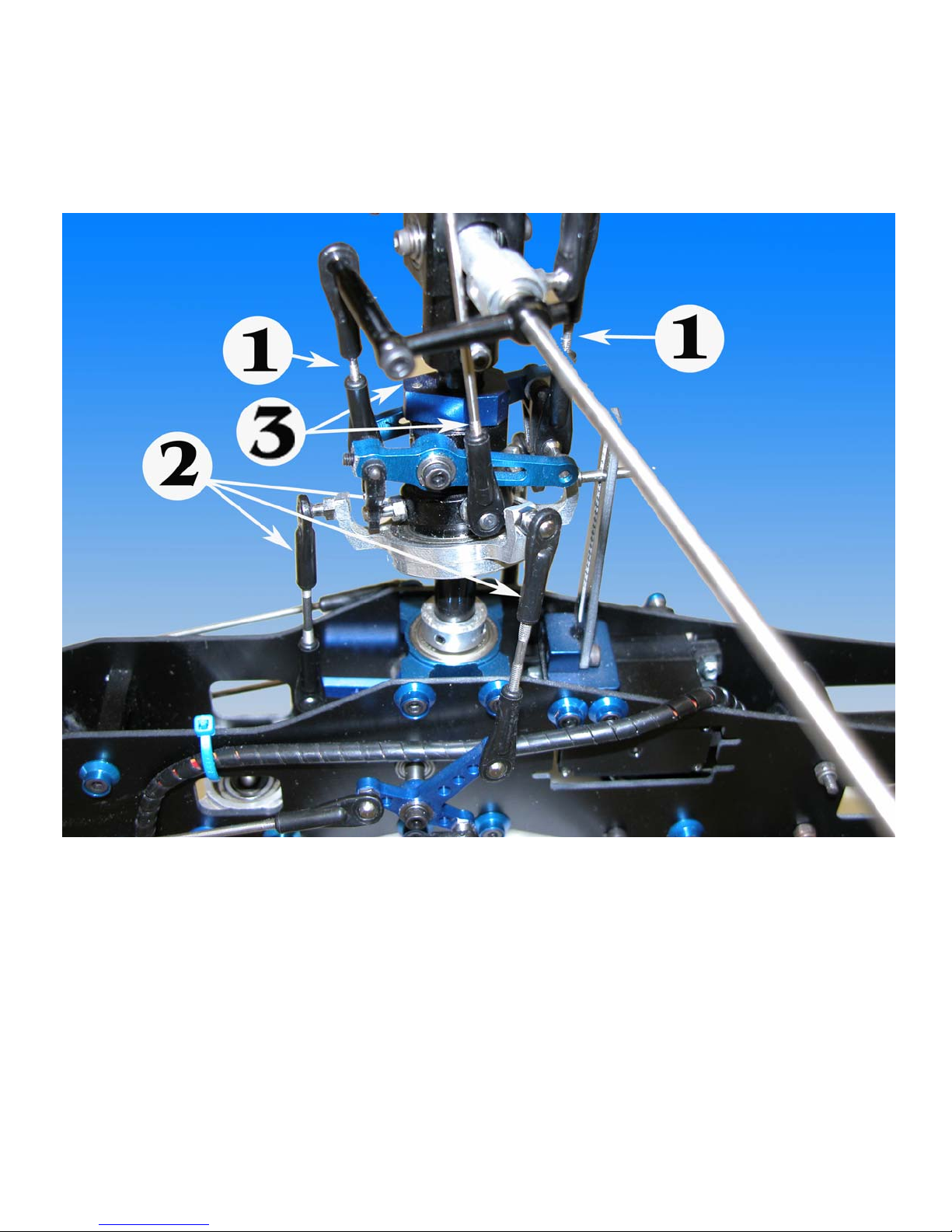
Page 67 of 85
Page 68
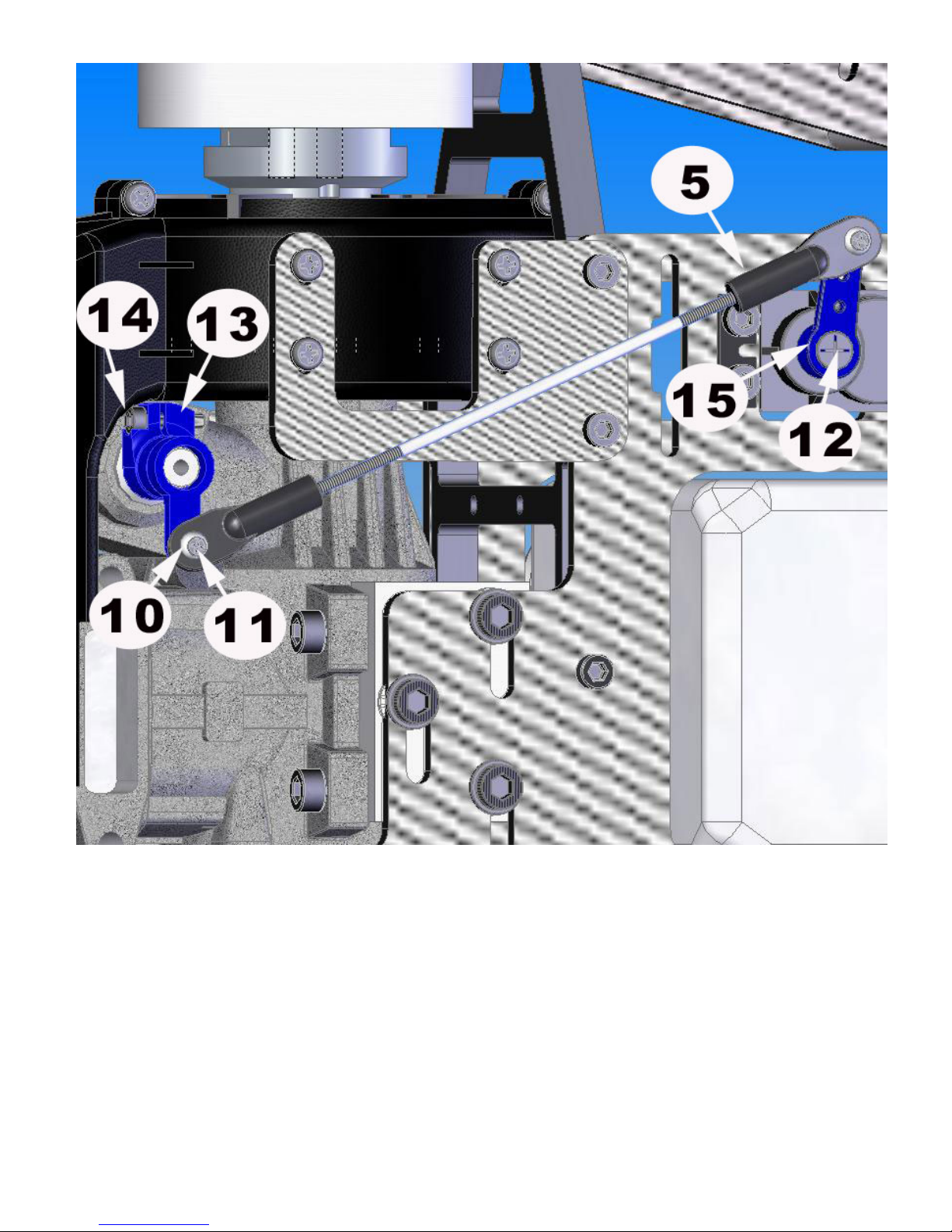
Note: the frame may look differently from the one in the kit.
Page 68 of 85
Page 69
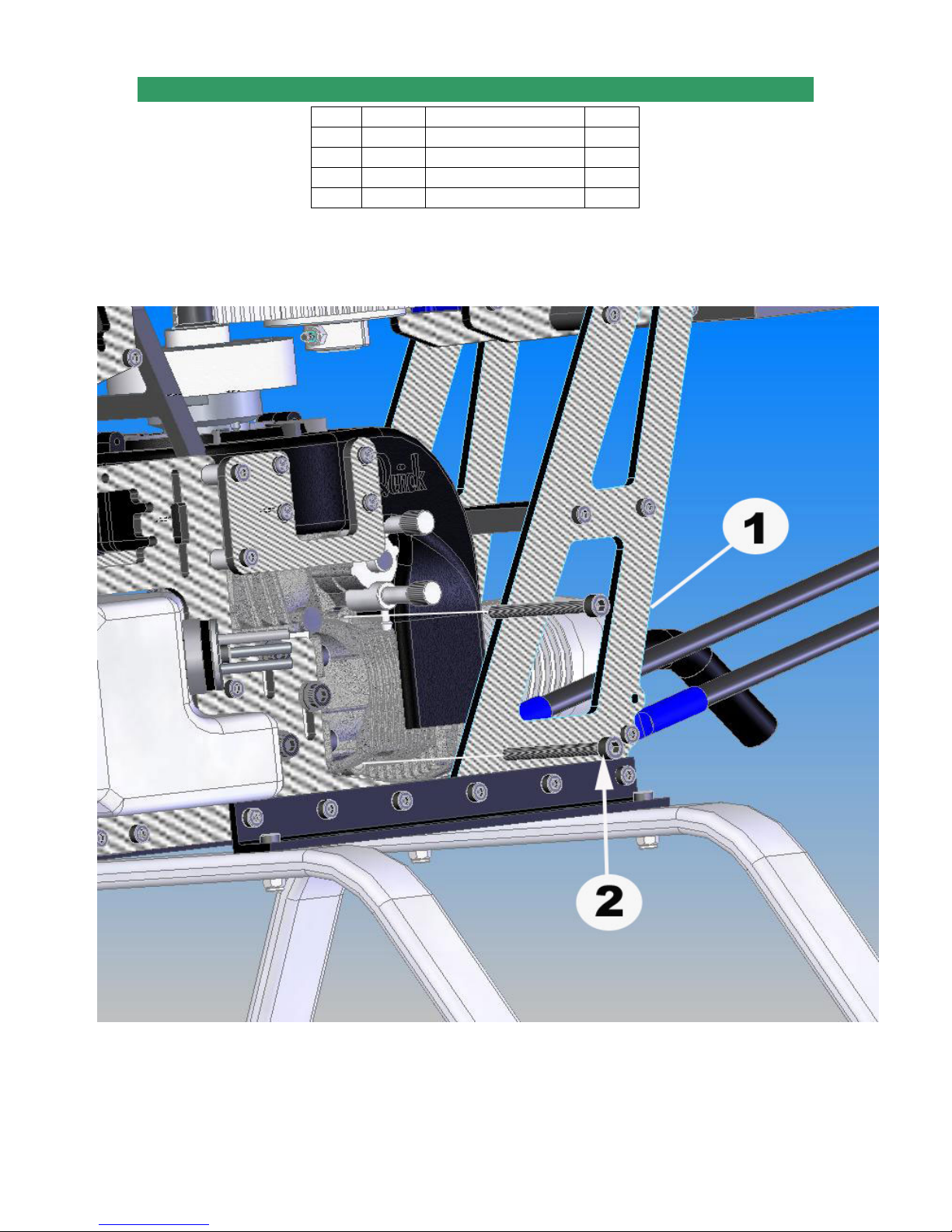
8-4 MUFFLER & HOSES ASSEMBLY
No. Bag# Description Qty.
1*****
2*****
3*****
4*****
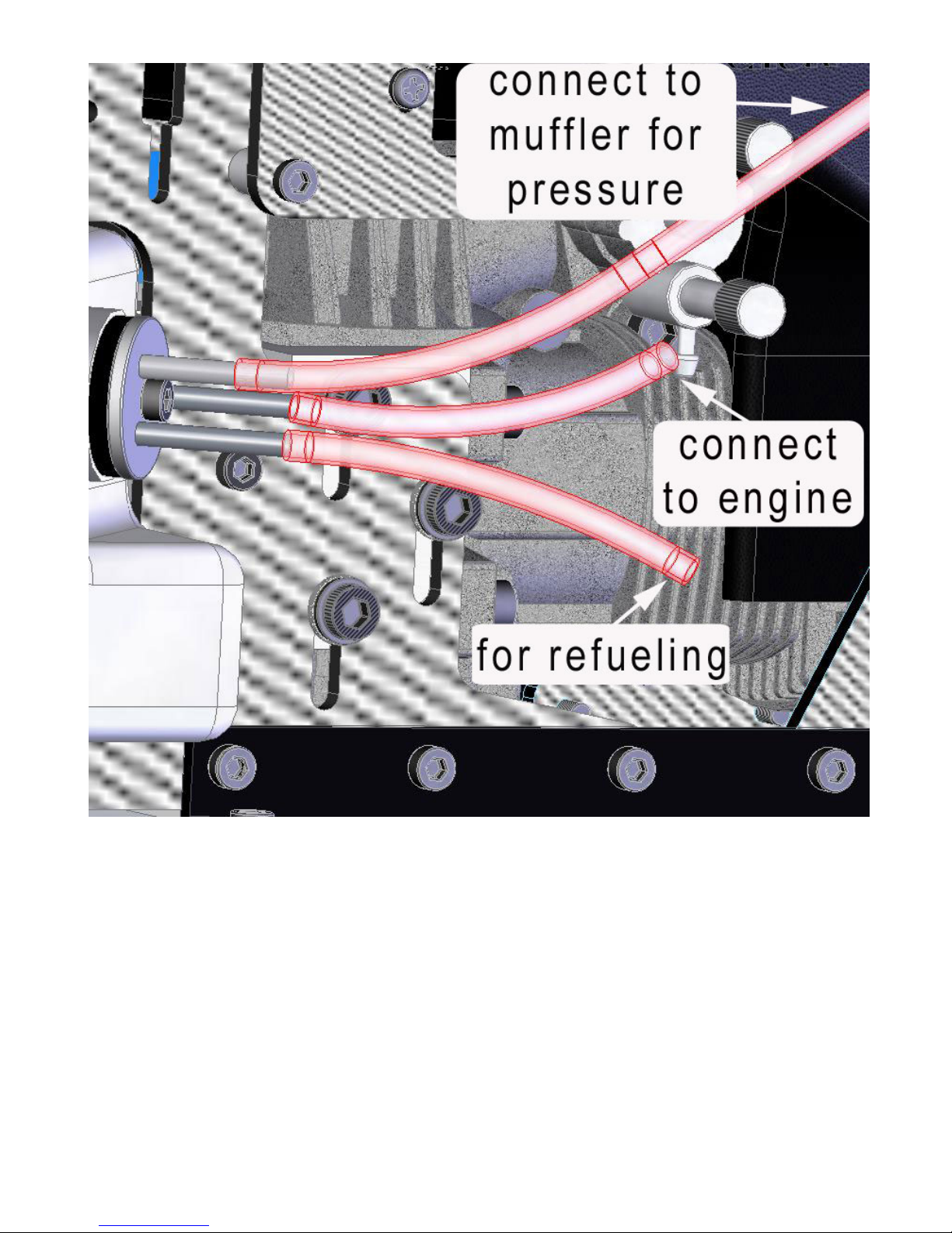
Note: For some kinds of engines and mufflers, you may have to cut the frame angle to
make room for screws to fit. Although the drawings do not show the valves for hoses,
you need to put one somewhere between the fuel tank and the engine; the other for
refueling hose.
The frame may look differently from the one in the kit.
Muffler 1
M3x35 Cap Head Bolt 2
Hose 3
M3 Locknut 2
Page 69 of 85
Page 70
Page 70 of 85
Page 71
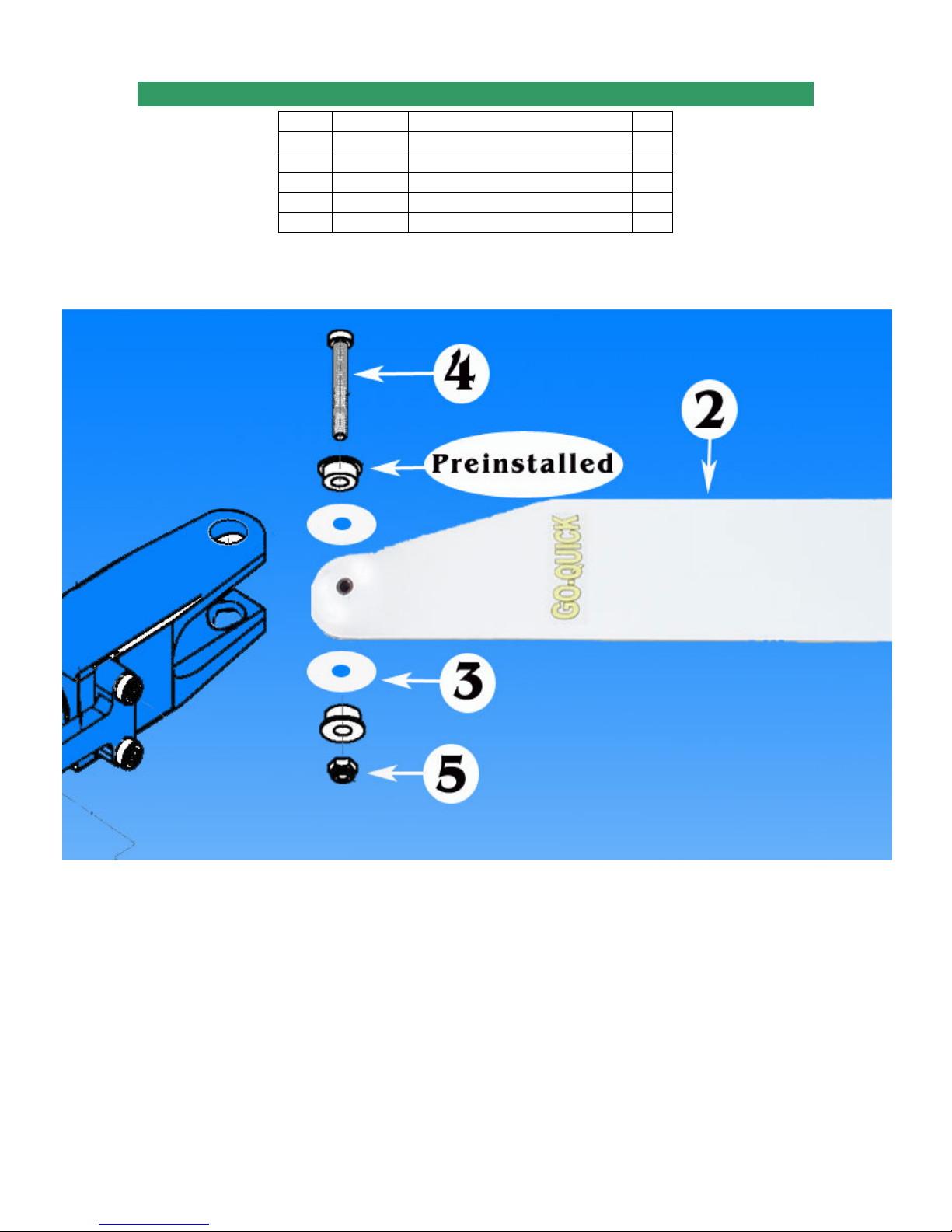
8-5 MAIN BLADE INSTALLATION
No. Bag# Description Qty
1
2*****
3*****
4 HB M4x30 Cap Head Bolt 2
5 HB M4 Locknut 2
Step 8-4
Helicopter (up to step 8-4) 1
Main Blade 2
Main Blade Spacer 4
Page 71 of 85
Page 72

8-6 RADIO SETUP
No. Bag# Description Qty
1
2
3
4
5 ***** Battery for Receiver 1
Step 8-5
*****
*****
*****
Before setting up the radio, you have to install the receiver, gyro, and batteries for your
helicopter. See your radio, receiver, and gyro manuals for how to hook up.
Helicopter (up to step 8-5) 1
Radio 1
Receiver 1
Gyro 1
Note: The frame may look differently from the one in the kit.
Instead of giving you the exact length of each linkage rod we will explain to you what you
are trying to achieve. This is the same for all Quick helicopters. Another thing worth
mentioning is that all controls on our helicopters are leading edge controlled. We have
three such controls on our helicopter and they are Main blades, Tail blade and flybar
control arms. For example the main blade pitch arms should be mounted so they are in
Page 72 of 85
Page 73
front of the blades in the direction of travel, clockwise if you look at the helicopter from
above, see picture 4. Your radio manual will be needed during this set up.
First, set your radio so that all travel values are at 100%. If you have a radio with Swash
Mixing set, ser those values to 50% (Aileron, Elevator, and Pitch.) Then use servo
reversing so that all servos are moving in the right direction. If Pitch operates reversed,
change the value in the Swash Mixing from + to -.
Step 1:First set your radio up so that all servos are moving in the right direction and
adjust all travel values to 100%. If you have a radio with Swash mixing values set those
to 50% (Pitch, Aileron and Elevator).
Now center both radio sticks (including “throttle”) and center all trim and sub-trim values.
When this is done turn your receiver pack on. Now mount the servo arms at a 90
towards the linkage rod. In our non push pull helis this will be horizontal. Use the
mounting position on the servo arm that will be closest to 90
100% correct. If they are visible off from the 90
o
position the use the sub-trim function in
o
, not all servos will line up
o
angle
your radio for fine tuning, do not use regular trim for this, see picture 1.
Now you have a good start and the rest of the setup will become easier.
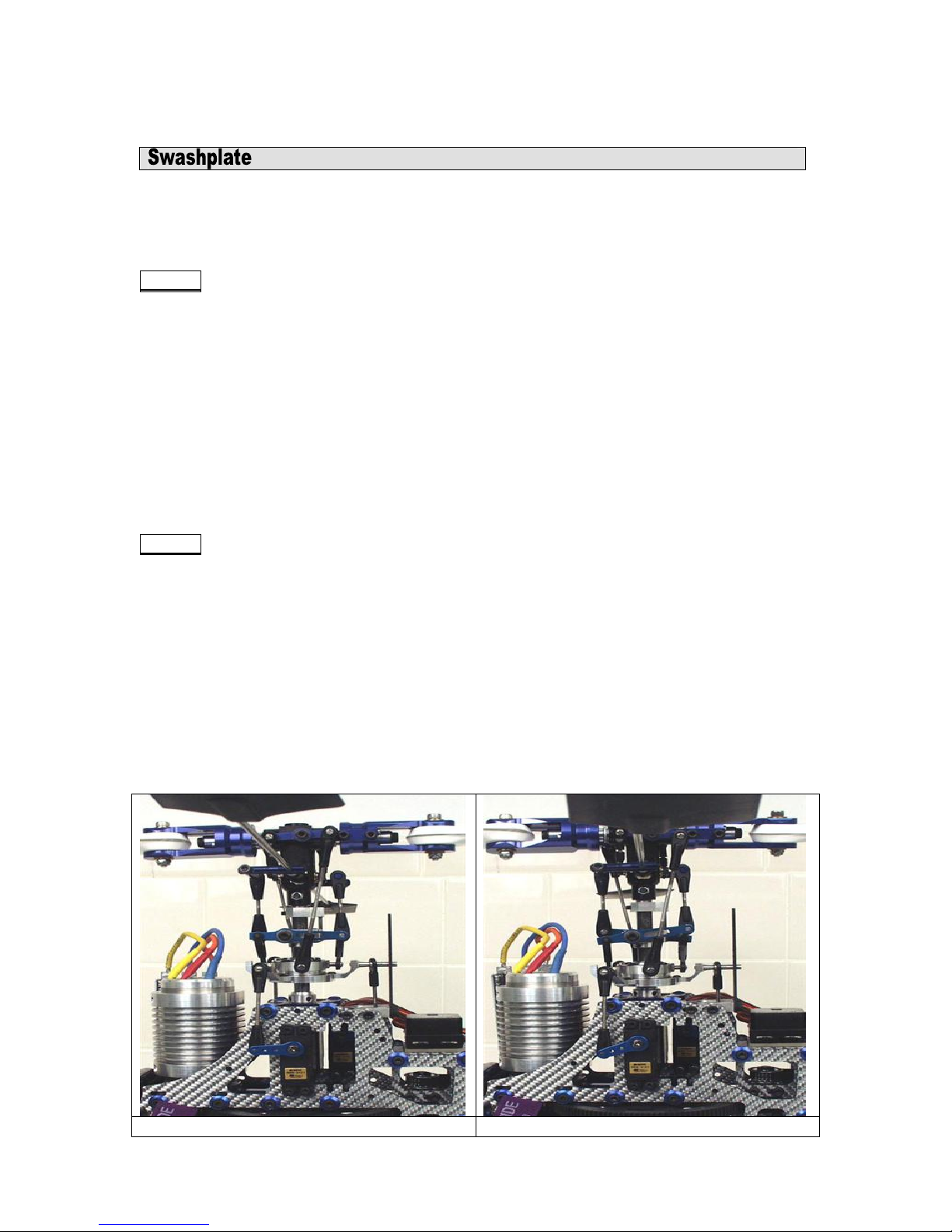
Step 2:Connecting the Swashplate at the right distance. This is done by moving your
Pitch (throttle) stick all the way down, see picture 2. When the servos are in this position
adjust the length of the linkage rods so the Swashplate is located towards the bottom,
but still leaves enough room for left/right (aileron) and front/back (elevator) travel. During
such travel, portions of the Swashplate will move below the Swashplate position
archived during Pitch full down radio stick position. So make sure you leave enough
room for this extra travel, see picture 2 for recommended height. Also make sure that all
3 linkage rods between the servo arms and the Swashplate are the same, so the
Swashplate is level. It should not tilt in any direction; unless your right radio stick is
moved. If it lilts, and all linage rods are the same length, then go back to step one and
make sure your three servo arms have the same neutral position (horizontal on non
push pull helis).
Picture 1, Swash center Picture 2, Swash Down
Page 73 of 85
Page 74
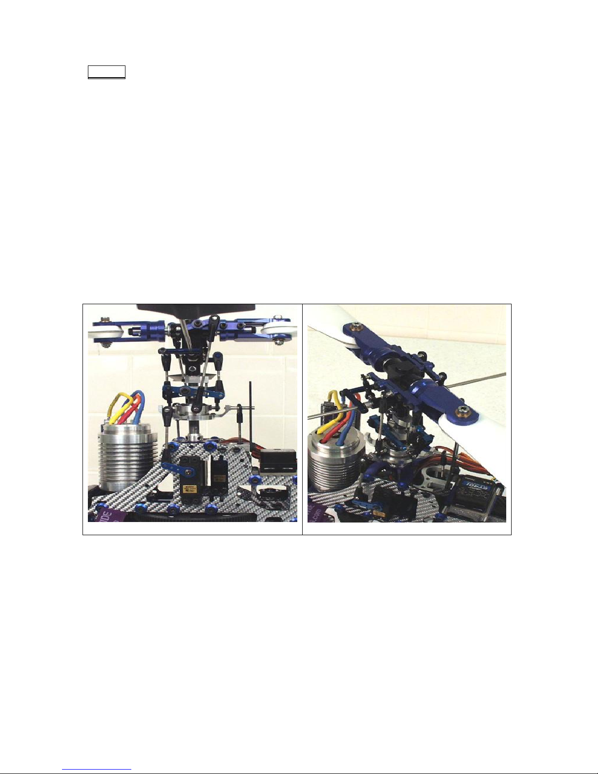
Step 3:Connecting the Washout assembly. Connect the fixed length plastic “A” arms to
the Swashplate, connect to the two longer pivot studs, if all four are the same length
then any two will do. The next step is to adjust the length of the linkage rod between the
Washout Arm and the Flybar connection point. Turn your radio and receiver back on and
center both sticks. Now adjust the length of the flybar linkage so the washout arms are
level (horizontal), see picture 1. Also make sure your flybar arms and flybar-paddles are
level (horizontal), when adjusting the linkage. After the length is adjusted make sure that
you have free travel in all directions and stick positions. When the Pitch stick is all the
way up it should look like picture 3. As you can see there is still plenty of room for aileron
and elevator travel. Now adjust the Washout Anti-rotation pin height so the pin is still in
the guide slot of the washout base during all travel positions. For the Left/Right Washout
Anti-rotation position, line the attachment point of the plastic washout “A” arm on the
Swashplate up with flybar linkage connection point. The imaginary line between these
points should be vertical.
Now you are almost done, only one set of links left, and the length of those links will be
depending on your desired setup whether it's Aerobatic or normal flying. Please refer to
the Pith travel setup table for this final link length.
Picture 3, Swash Up
Picture 4, Head
Page 74 of 85
Page 75
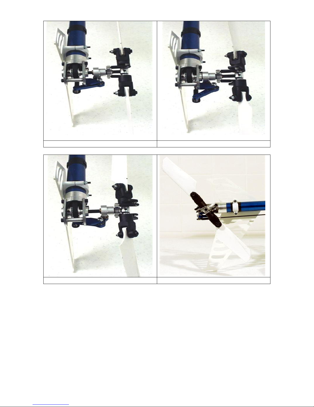
Picture 5, Tail Center Picture 6, Tail Positive Thrust
Picture 7, Tail Negative Thrust Picture 8, Tail
Page 75 of 85
Page 76

Pitch Travel Setup
Collective Position Normal Flying Aerobatic
Up (100%) +10o +10o
Center (50%) +5
Down (0%) -3o -10
o
+0o
o
Throttle Curve Setup
Flying
Electric
Aerobatic
Collective Position
Normal
Flying
Fuel
Aerobatic
(non governor mode)
Normal
Up (100%) 100% 100% 85% 85%
Center (50%) 70% 60% 75% 75%
Down (0%) 10% 100% 0% 85%
First adjust the servo arm position like you did with the swash, make sure your trim and
sub-trim values are centered. Attach the servo arm so it's 90
(vertical). Now adjust your two plastic ball ends, for the push rod, so they are screwed on
about half way onto the threaded pushrod guide end piece. This will allow you have
maximum amount of adjustment available in both directions. Use the outer holes on the
tail blade grips for the ball link attachments. When this is done cut the carbon pushrod to
a length that will achieve about 3
o
of positive pith on your tail blades, when the servo is
in its neutral (vertical) position. Then glue the two end pieces on to the pushrod with CA
glue, don't forget to insert the pushrod guides first.
o
When this is done you should have 3
of positive tail blade pitch. The tail should spin
counter clockwise looking at the right side of the helicopter with the nose to your right
and tail to your left. See pictures 5-8.
Note: Please consult the instruction for your Gyro for setting the overall travel and limits
to ensure proper operation and travel of Tail Pitch Slider.
o
to the tail pushrod
The throttle cure will be affected by several conditions; some of them are, motor choice,
blades choice, elevation, temperature, helicopter weight and type of helicopter. So in
order to explain this I will explain what you are looking for. Your goal is to achieve a
constant head speed once the helicopter is airborne. If you ad pitch (climb) you need to
ad power (throttle) to compensate for the added resistance a higher blade pitch creates.
If during climb your head speed drops, then you need to add throttle to that particular
stick position, and reversed if you have an increase in rpm. If during max climb out you
experience an increase in head speed then you need to give the blades a higher pitch,
do not try to adjust the max climb rpm by reducing throttle. There are other ways of
achieving this by using cyclic mixing, however we will stay away from this for now.
Follow the pitch guidelines in the table above, and if you need more pitch at max power
because the rpm is increasing, then add pitch. 10
Page 76 of 85
o
is just a guideline and will work in
Page 77

most setups, but a powerful motor or a light helicopter might need more. For rpm
adjustment during anything other than full stick deflection you should use the throttle.
A short recap, adjust throttle to adjust rpm during anything other than full collective. At
full collective adjust the pitch. See the Throttle table for general setup.
These are guidelines and will get you going but might not be 100% accurate in regards to
all helicopters. Especially the throttle curve table should be considered as initial guidelines.
As mentioned before it's greatly affected by your equipment. As you become more familiar
and proficient with your helicopter you can change the pitch and throttle curves to your
flying style.
Warning: to prevent the Flybar Paddle from falling off the Flybar, make sure to apply
Epoxy/JP Weld to the thread on Flybar and the Flybar Paddle after finishing Setup.
Page 77 of 85
Page 78
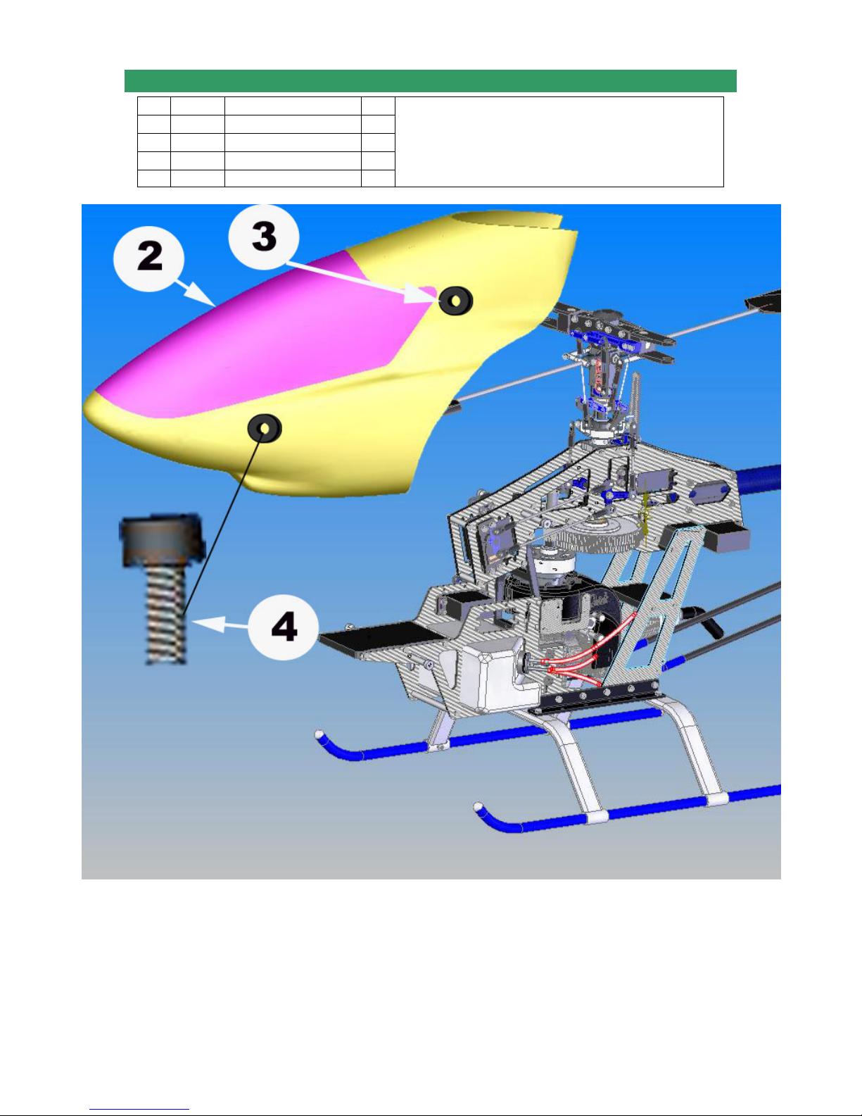
8-7 CANOPY INSTALLATION
No. Bag# Description Qty
1
2
In box
3 8 Canopy Grommet 4
4 HB M3x16 Cap Head Bolt 4
Helicopter 1
Canopy 1
• Put the Canopy on the helicopter, mark the right
positions for 4 holes, and then drill four 5.5mm holes.
• Install the Canopy Grommets on the Canopy.
• Secure the Canopy by 4 M3x16 Cap Head Bolts.
Note: The frame may look differently from the one in the kit.
Page 78 of 85
Page 79
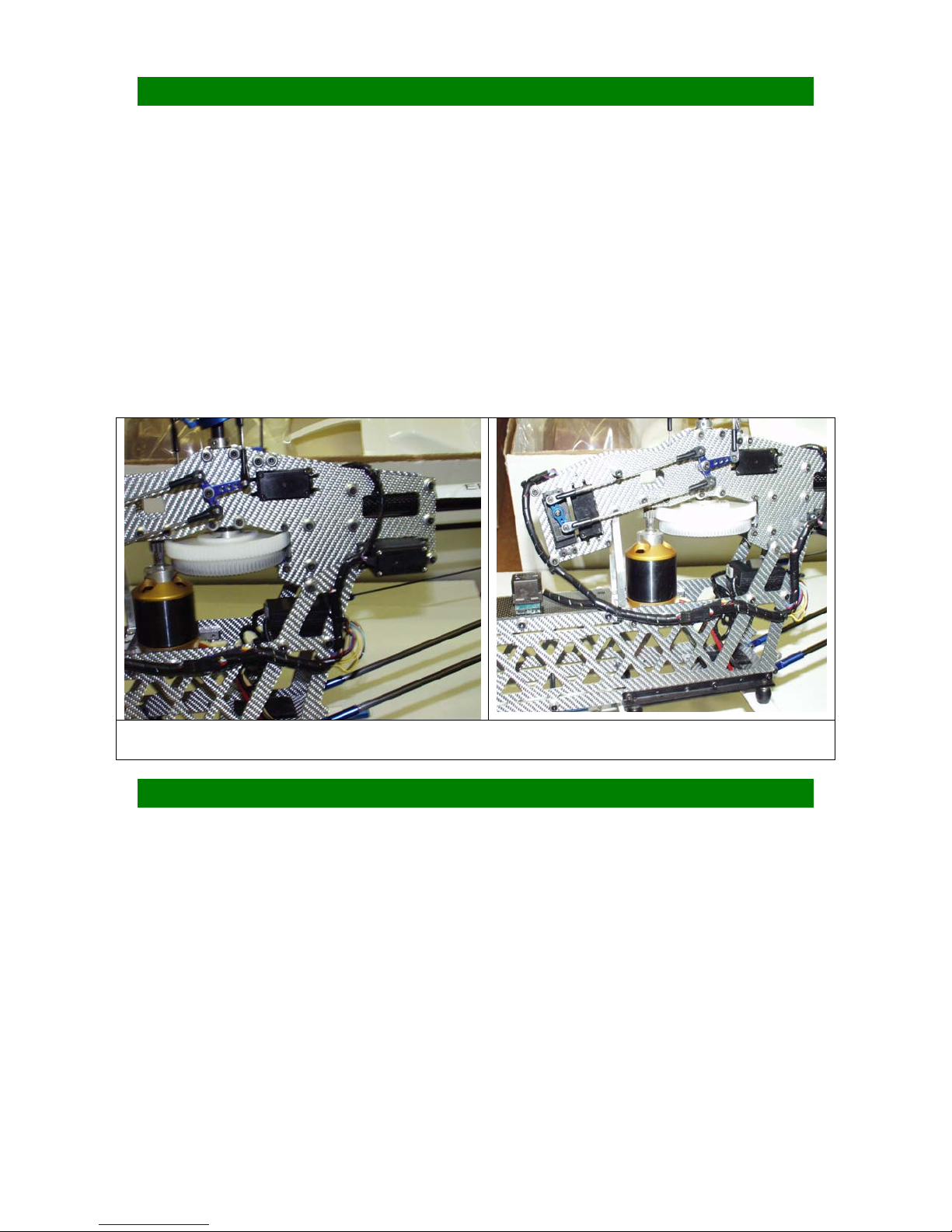
PRE-FLIGHT CHECKS
• The rotor flybar and shaft must be straight.
• The flybar and control paddles must tilt in the proper direction and operates smoothly
throughout the whole range.
• Check the swashplate to make sure it move smoothly and clean.
• When control input are given to tilt the swashplate, make sure no control arms or
pushrods are binding.
• Check the two control paddles for level, parallel, and proper direction.
• Make sure the batteries are fully charged and the fuel tank is full.
• Make sure the radio and receiver are on and all controls operate properly before
flight.
• There should be no interference of radio signal in your flying zone. Range check the
radio.
• Always grab onto the helicopter main rotor head when turning on the helicopter.
These pictures illustrate how everything should be neatly wired up and strapped down
before your helicopters first flights.
WARNINGS
•
Do not operate helicopters in rainy, windy, or snowy condition.
•
Operate helicopter in a safe zone away from crowds, traffic, or distractions.
•
Use the proper batteries to prevent damage to the motor and equipment.
•
Make sure all the batteries are fully and properly charged and the fuel tank is full.
•
Make sure all the controls operate properly before flight.
•
The main and tail rotors blades operate at very high speed (rpm); therefore,
make sure nothing can come into contact with them while they are spinning.
•
Perform a range check on the radio before flying.
•
Make sure the transmitter and receiver are turned on before starting the engine
•
Keep a safe distance when operating a helicopter.
•
Do not fly for a long period of time. Take some rests during flights.
Page 79 of 85
Page 80
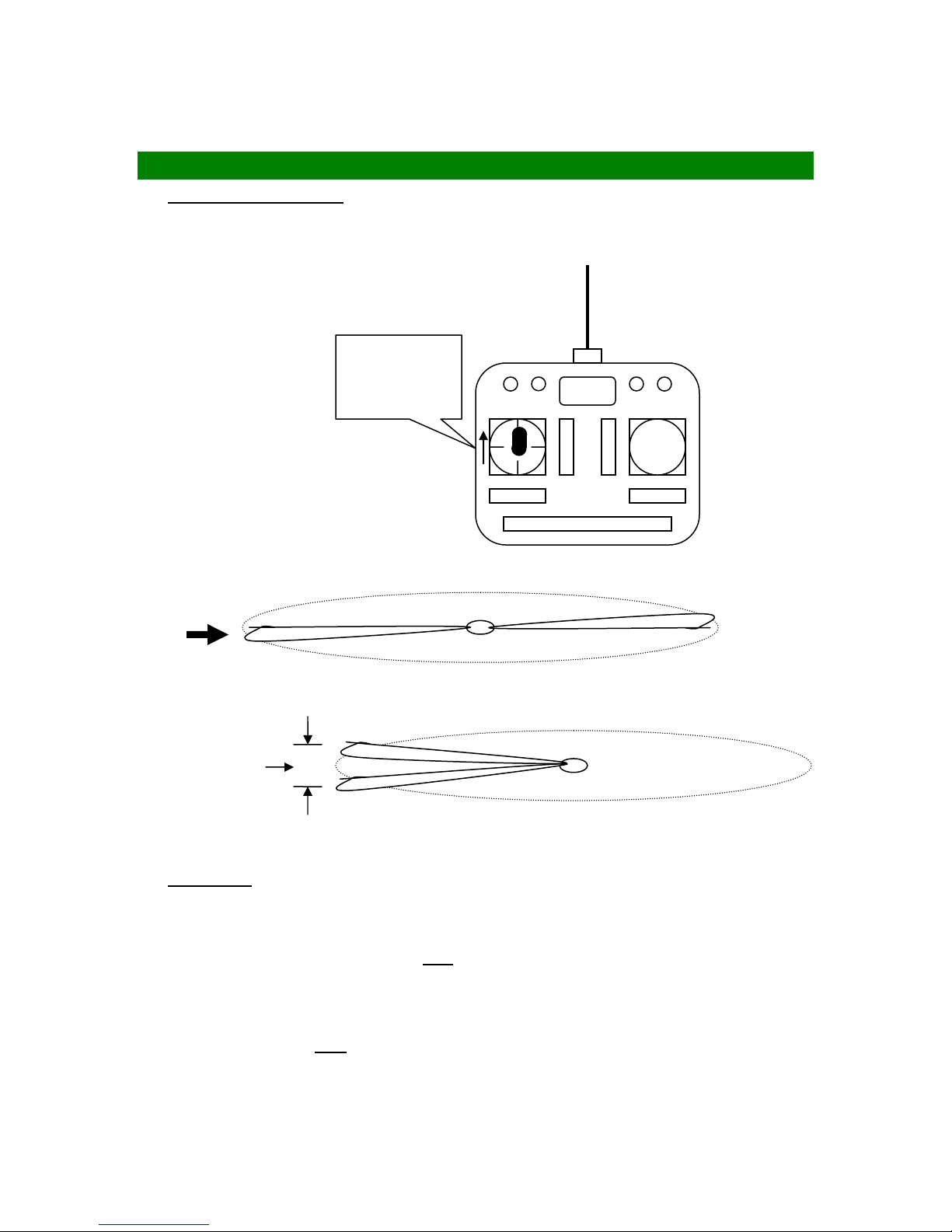
• Motors are often very hot after operation. So be careful when handling or
touching them immediately after flying.
ADJUSTMENTS
Tracking Adjustment: The tips of the main rotor blades should follow the same
path when they rotate. We call the main rotor blades are in track.
(a) Rev up the motor until the helicopter becomes light on its landing gear.
Raise throttle
gently and
gradually
(b) If the main rotor blades are in track, it’s good.
(c) If the blades are out of track, then adjust one of the pushrods that connect to the
main rotor blade pitch arm.
Out of track
Repeat steps (a) to (c) until the blades are in track.
Trimming: Most of new built helicopters are unstable. But if you trim your helicopter
properly, you will stop it from drifting away or yawing by itself quickly. Followings are
instructions for trimming your helicopter.
(a) If the helicopter nose starts to
compensate. If using a Heading Hold Gyro, do not adjust the trim lever on the radio.
yaw left or right, adjust the tail rotor push rod to
(b) If the helicopter rolls to left or right, then:
Page 80 of 85
Page 81
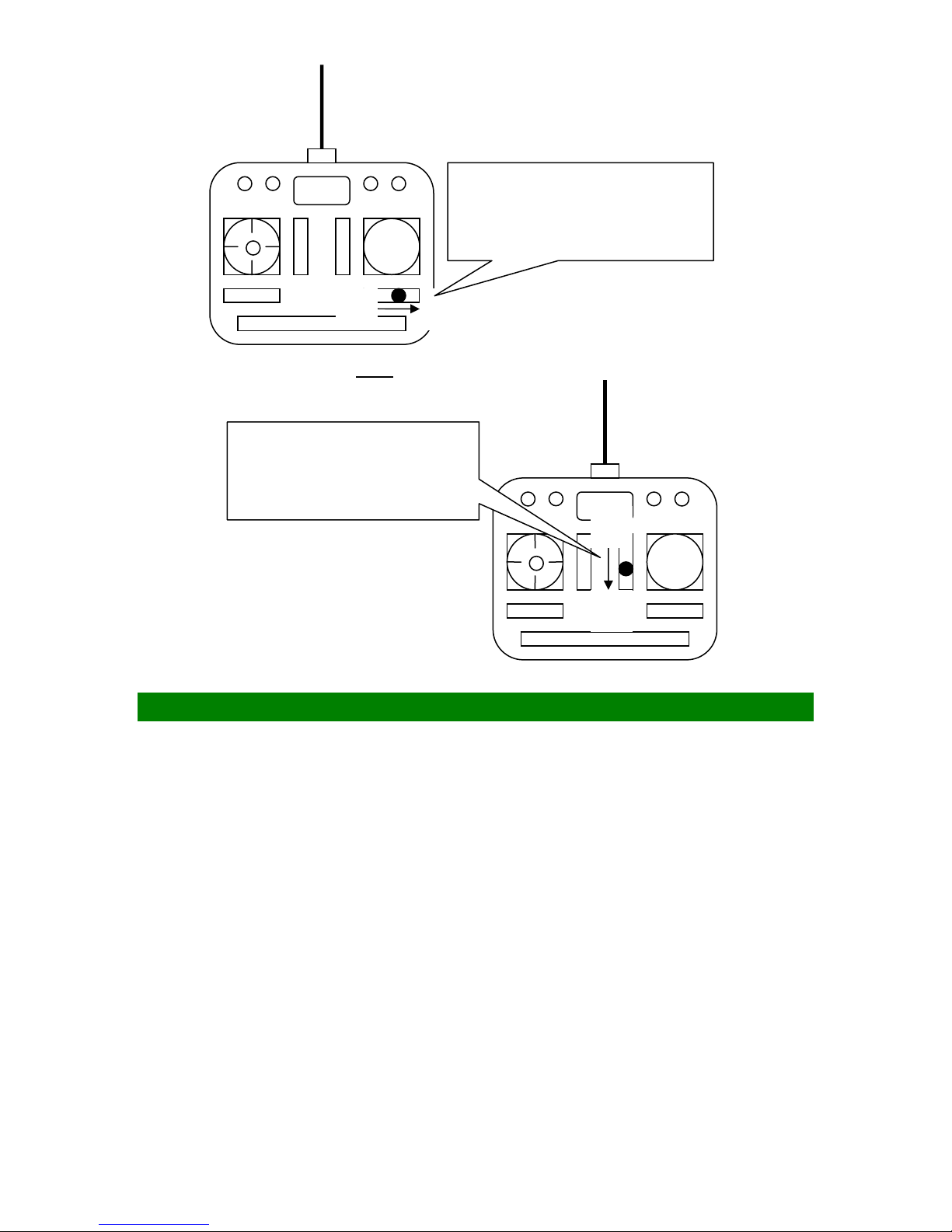
•
Rolls to the left, move the
button to R
• Rolls to the right, move the
button to L
L R
(c) If the helicopter nose goes down or up, then:
• Goes up, move the stick
to U
• Goes down, move the
stick to D
U
D
HOW TO HOVER
Basic maneuver for a pilot is learning how to hover a helicopter. When the helicopter is
floating in a stationary position in the air, we call that hovering. Use the following
procedure to practice your hovering:
(a) Make sure everything is clear in the flying zone. Stand at least 30 feet (10 meters)
behind the helicopter.
(b) Check the main rotor fore/aft and left/right cyclic to make sure the main rotor is
following to your cyclic command before taking off. Make sure the helicopter nose
will swing in your desired directions by moving the tail rotor control stick.
(c) Now, increase the throttle/collective gently to lift the helicopter landing gear off the
ground to no more than 4 inches (10 cm). At the beginning, it is very difficult for the
pilot to keep the helicopter from moving. It will also be difficult to know if the
helicopter is in trim or not for a beginner. Keep going on the practice close to ground
you will develop your skills.
(d) Keep practicing lifting your helicopter no more than 8 inches (20cm) from the ground
until you feel comfortable with control commands. Once you can keep it at one place,
then it is time to slowly increase the height a few inches in each fight. Soon, you will
be able to hover the helicopter confidently at a few feet high. Beginners should
Page 81 of 85
Page 82
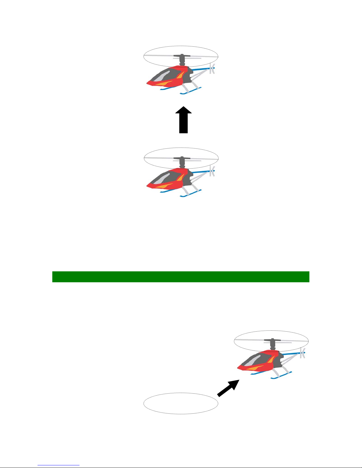
always practice hovering close to ground since in an emergency situation; you can
drop the throttle and collective quickly without making any big damage.
4 ~ 8 inches
(e) Stand behind the helicopter so you can watch the nose of the helicopter. A left tail rotor
command will yaw the helicopter nose to the left, and a right command will yaw to the
right. Also, a left cyclic command will cause the helicopter to translate left., Start
practice hovering while standing to either side of the model after you can comfortably
hover the helicopter at 3 feet (1m) high without drifting. Finally, you need to learn
hovering the model from any positions. When you can confidently hover a helicopter at
any altitude and at any position, you have mastered most of the fundamental control
movements of a helicopter.
HOW TO FLY FORWARD
Once you have mastered hovering fight:
(a) Let’s begin the exercise of changing positions by practice moving the helicopter to
the left or right slowly from 60 inches (1.5 m) above the ground.
Page 82 of 85
Page 83
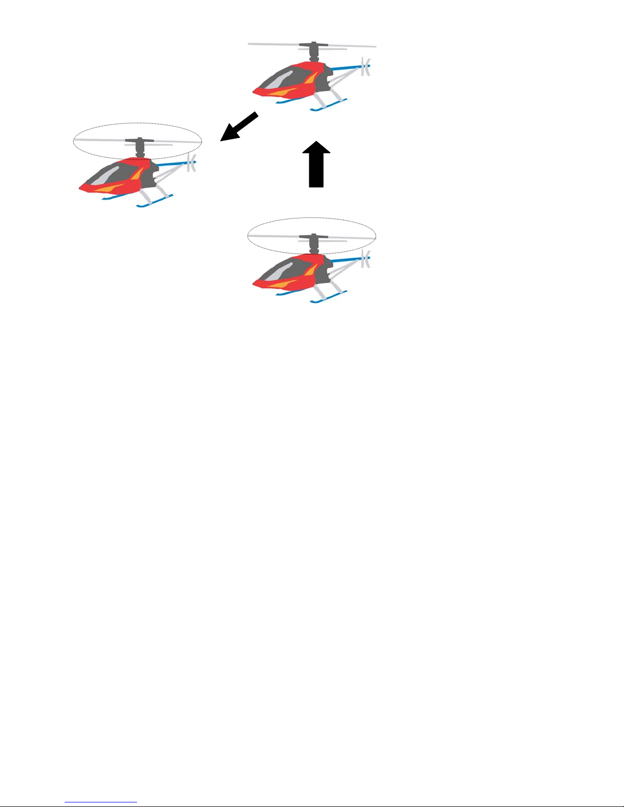
Hovering at 60 inches
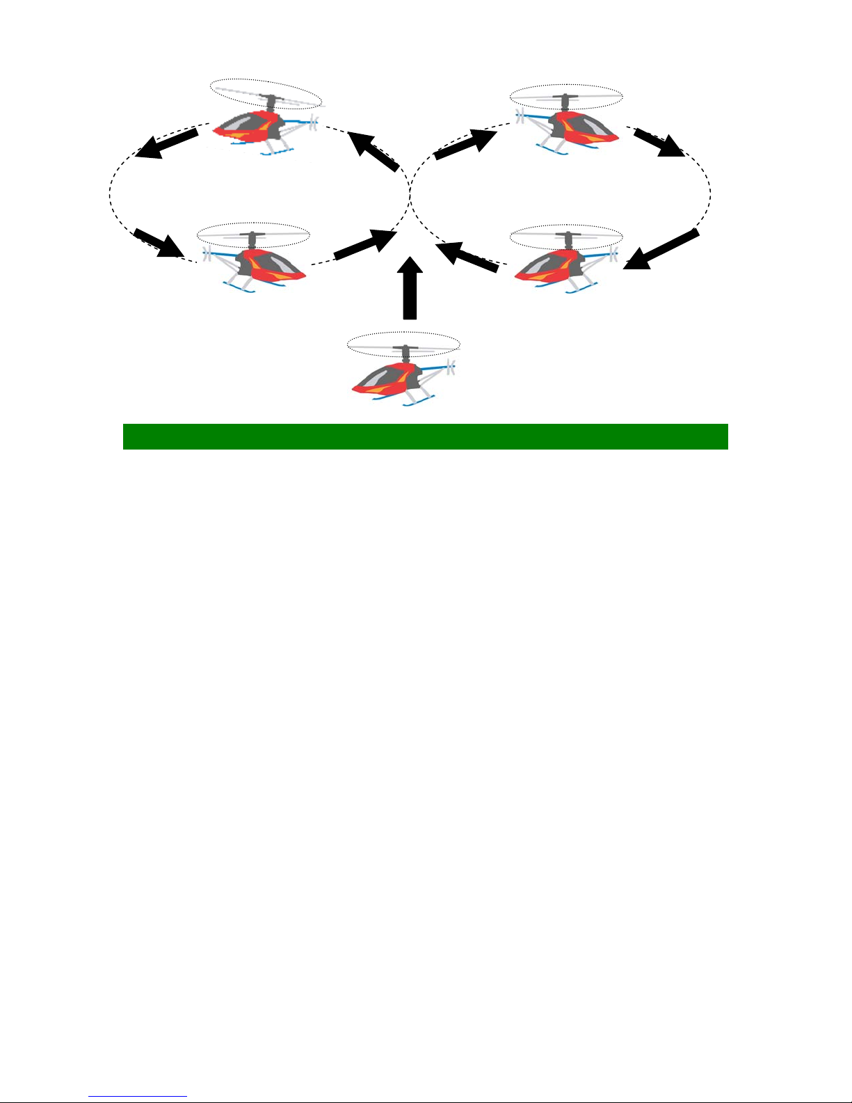
(b) Once you have been comfortable with all the movements and controls in the
previous step, start using some tail rotor control to make the helicopter point slightly
to the left or right as you fly it to the left or right. Keep practicing the figure-eight path
as shown below, you will master all basic control movements of a helicopter.
Page 83 of 85
Page 84
AFTER-FLIGHT CHECKS
After each flight, the helicopter should be thoroughly inspected:
(a) Unplug the batteries.
(b) Check every bolt, nut, and screw to make sure none has loosened due to vibration.
(c) Check every rotating and movable part like head rotor, swashplate, tail rotor, to ensure
they still move smoothly and properly.
(d) Check all movable parts, such as gears, ball links, belt, etc. for unusual wear.
(e) Clean up the helicopter then lubricate every moving part with oil to ensure a smooth
operation in the future.
(f) Keep the helicopter in a cool and dry place. Avoid storage under direct sun light or
near heat.
(g) Please replace any damaged parts if they are discovered during maintenance.
Page 84 of 85
Page 85

WHAT IF THE HELICOPTER CRASHED
Turn off everything and check the helicopter immediately. If any item is damaged,
replace the damaged parts to ensure safe operation. Do not try to glue any broken or
damaged plastic or carbon parts specially broken rotor blades. The followings are parts
that should be inspected right away:
• Main and tail rotor blades.
• Flybar, main shaft, head spindle, and tail output shaft.
• All the gears.
• Tail boom and supports for cracks.
• Vertical and horizontal fins.
• Frames.
• All pushrods.
• Servos, motor, and batteries.
SPECIFICATIONS
Specification Super Learner
Blades Quick 520-580 mm
Length 1025 mm
Height 405 mm
Fully Equipped Weight ~ 6.0 lbs (2.72 kg)
Engine 32-37-46
Frame Thickness 2.0-2.2 mm
Spindle 8.0 mm
Main Shaft 10 mm
Canopy Fiberglass
Flying Aerobatic / 3D
Page 85 of 85
 Loading...