

QL5030 QuickPCI Data Sheet Rev C
1
•
•
•
•
•
•
• • • • • •
QL5030 QuickPCI Data Sheet
33 MHz/32-bit PCI Target with Embedded Programmab le Logic
and Dual Port SRAM
1.0 Device Highlights
High Performance PCI Controller
• 32-bit / 33 MHz PCI Target
• Zero-wait state PCI Target Provides 132
MB/s Transfer Rates
• Programmable Back-end Interface to
Optional Local Processor
• Independent PCI bus (33 MHz) and Local Bus
• (up to 160 MHz) Clocks
• Fully Customizable PCI Configuration Space
• Configurable FIFOs with Depths up to 128
• Reference Design with Driver Code
(Win 95/98/Win 2000/NT4.0) Available
• PCI v2.2 Compliant
• Supports Type 0 Configuration Cycles
• 3.3V, 5V Tolerant PCI Signaling Supports
Universal PCI Adapter Designs
• 3.3V CMOS in 144-pin TQFP
• Supports Endian Conversions
• Unlimited/Continuous Burst Transfers
Supported
Extendable PCI Functionality
• Support for Configuration Space from 0x40
to 0x3FF
• Multi-Function, Expanded Capabilities, &
Expansion ROM Capable
• Power Management, Compact PCI,
Hot-swap/Hot-plug Compatible
• PCI v2.2 Power Management Spec
Compatible
• PCI v2.2 Vital Product Data (VPD)
Configuration Support
• Programmable Interrupt Generator
• I2O Support with Local Processor
• Mailbox Register Support
Programmable Logic
• 24K System gates / 266 Logic Cells
• 9,216 RAM bits, 71 I/O pins
• 250 MHz 16-bit counters, 275 MHz
Datapaths, 160 MHz FIFOs
• All Back-end Interface and Glue-logic can be
Implemented on Chip
• 4 64-deep FIFOs (2 RAMs each) or 2 128-
deep FIFOs (4 RAMs each) or a Combination
that Requires 8 or less QuickLogic
RAM Modules
• (2) 32-bit Busses Interface between the PCI
Controller and the Programmable Logic
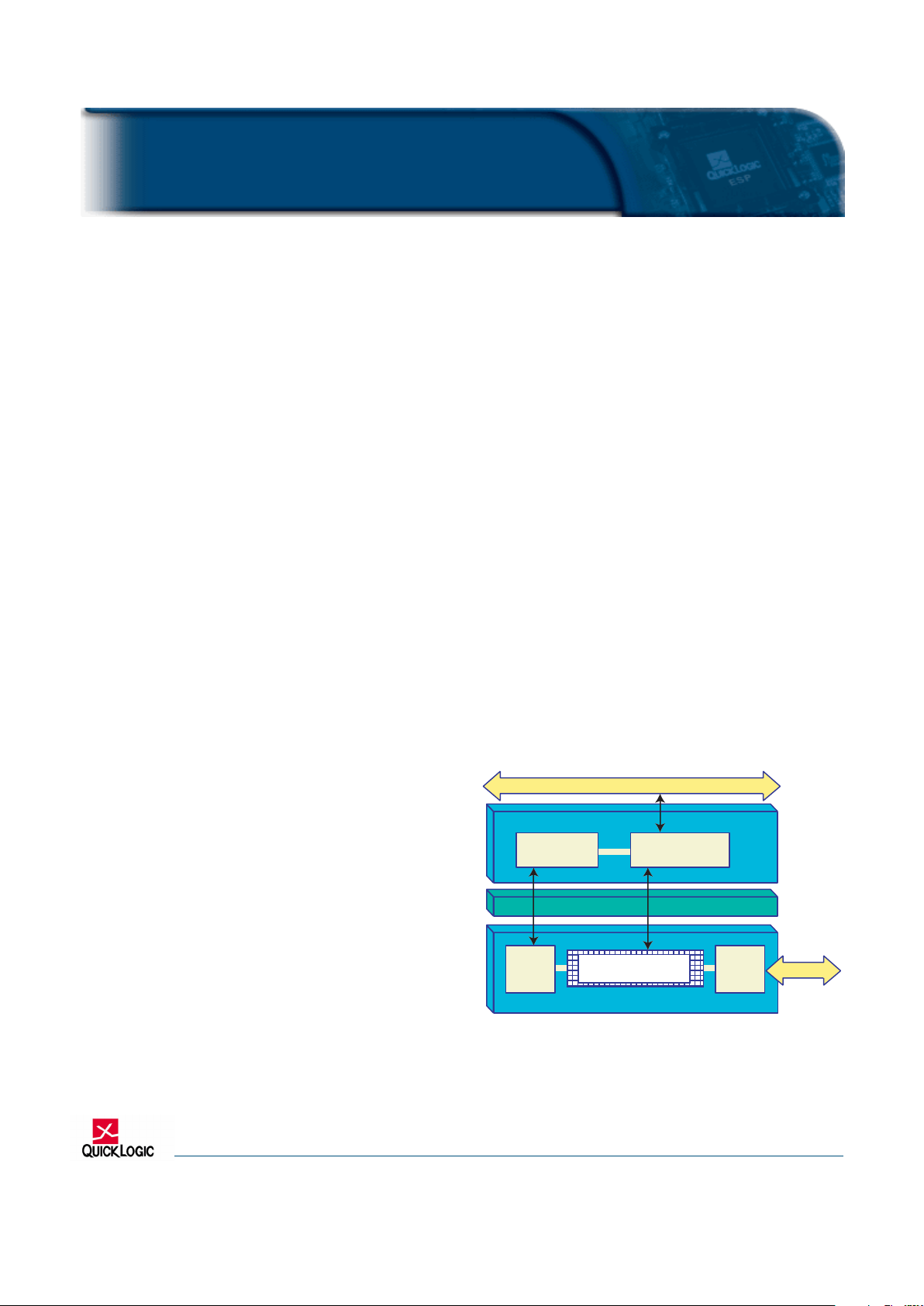
Figure 1: QL5030 Block Diagram
PROGRAMMABLE LOGIC
PCI CONTROLLER
INTERFACE3232
71 User I/O
PCI Bus - 33 MHz 32 Bits (Data and Address)
Target
Controller
High Speed
Data Path
160 MHz
FIOFs
Config
Space
High Speed Logic Cells
24K Gates

2
www.quicklogic.com
© 2002 QuickLogic Corporation
•
•
•
•
•
•
QL5030 QuickPCI Data Sheet
2.0 Architecture Overview
The QL5030 device in the QuickLogic QuickPCI ESP (Embedded Standard Product) family provides a
complete and customizable PCI interface solution combined with 24,000 system gates of programmable
logic. This device eliminates any need for the designer to worry about PCI bus compliance, yet allows
for the maximum 32-bit PCI bus bandwidth (132 MB/s).
The programmable logic portion of the device contains 266 QuickLogic Logic Cells, and 8 QuickLogic
Dual-Port RAM Blocks. These configurable RAM blocks can be configured in many width/depth
combinations. They can also be combined with logic cells to form FIFOs, or be initialized via Serial
EEPROM on power-up and used as ROMs. See the RAM section of this data sheet for more information.
The QL5030 device meets PCI 2.2 electrical and timing specifications and has been fully hardwaretested. This device also supports the Win'98 and PC'98 standards. The QL5030 device features 3.3-volt
operation with multi-volt compatible I/Os. Thus it can easily operate in 3.3-volt systems and is fully
compatible with 3.3V, 5V or Universal PCI card development.
2.1 PCI Interface
The PCI target is PCI 2.2 compliant and supports 32-bit/33 MHz operation. It is capable of zero waitstate infinite-length read and write transactions (132
MBytes/second). Transaction control is available via
the user interface as retries, wait-states, or premature transaction termination may be induced if
necessary. The PCI configuration registers are implemented in the programmable region of the device,
leaving the designer with ample flexibility to support optional features.
The QL5030 device supports maximum 32-bit PCI transfer rates, so many applications exist which are
ideally suited to the device's high performance. High-speed data communications, telecommunications,
and computing systems are just a few of the broad range of applications areas that can benefit from the
high speed PCI interface and programmable logic.
2.2 PCI Configuration Space
The QL5030 supports customization of required Configuration Registers such as Vendor ID, Device ID,
Subsystem Vendor ID, etc.. QuickLogic provides a reference Configuration Space design block.
Since the PCI Configuration Registers are implemented in the programmable region of the QL5030,
the designer can implement optional features such as multiple 32-bit Base Address Registers (BARs) and
multiple functions, as well as support the following PCI commands: I/O Read, I/O Write, Memory Read,
Memory Write, Config Read (required), Configuration Write (required), Memory Read Multiple, Memory
Read Line, and Memory Write and Invalidate. Additionally, the device supports Extended Capabilities
Registers, Expansion ROMs, power management, CompactPCI hot-plug/hot-swap, Vital Product Data,
I
2
0, and mailbox registers.
2.3 Address and Command Decode
PCI address and command decoding is performed by logic in the programmable section of the device.
This allows support for any size of memory or I/O space for back-end logic. It also allows the user to
implement any subset of the PCI commands supported by the QL5030. QuickLogic provides a
reference Address Register/Counter and Command Decode block.
QL5030 QuickPCI Data Sheet Rev C
3
•
•
•
•
•
•
QL5030 QuickPCI Data Sheet
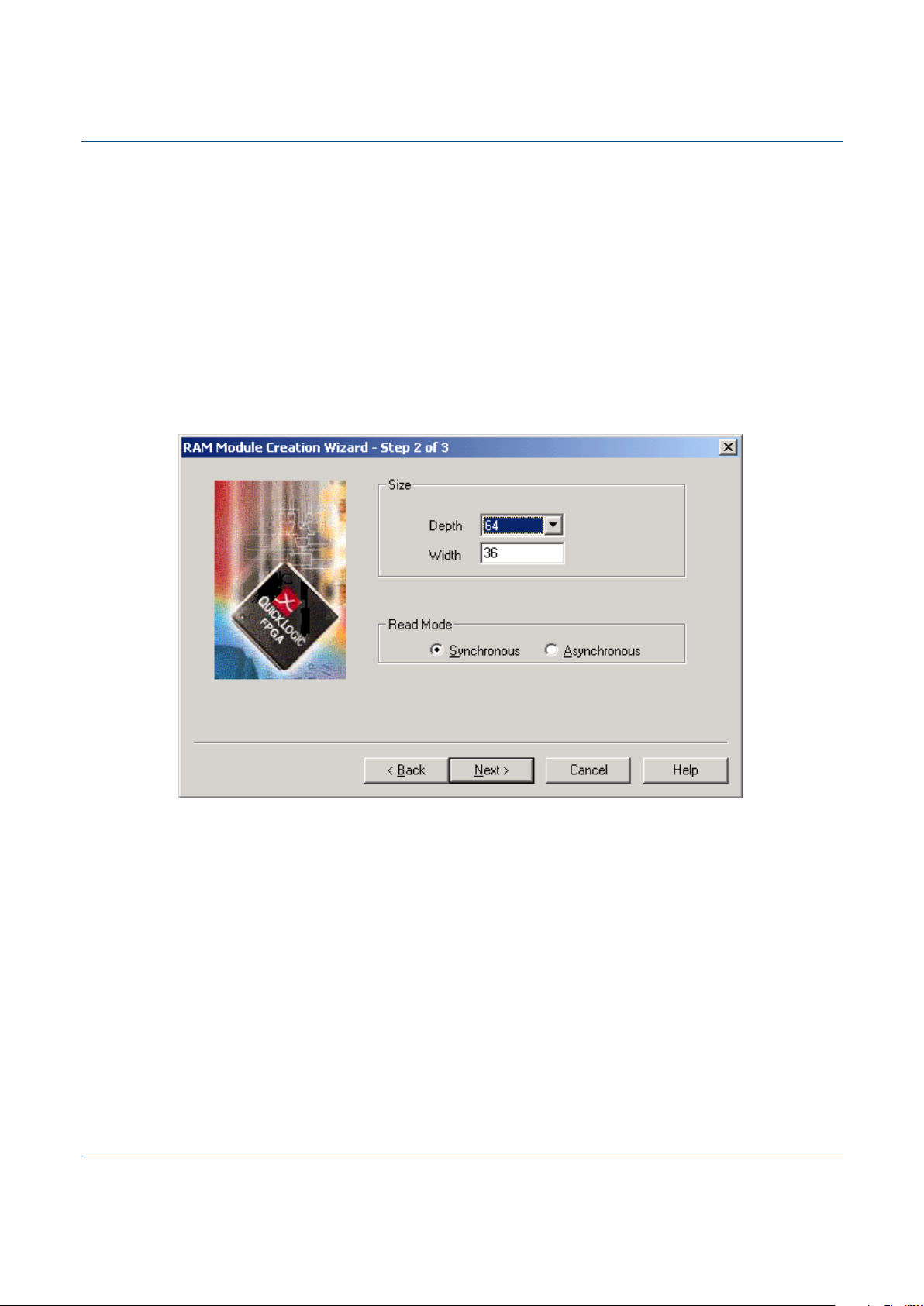
3.0 RAM Architecture Overview
The RAM modules in the programmable region can be used to create configurable 32-bit FIFOs. Each
32-bit FIFO can be independently assigned to Target address space for read pre-fetch or write posting.
Using the 8 QuickLogic RAM modules, the combinations include:
• 4 independent 64-deep FIFO (2 RAMs each),
or
• 2 independent 128-deep FIFOs (4 RAMs each),
or
• a combination of the above that requires 8 or less QuickLogic RAM Modules
Asynchronous FIFOs (with independent read and write clocks) are also supported.
Figure 2: Graphical Interface to create FIFO
4
www.quicklogic.com
© 2002 QuickLogic Corporation
•
•
•
•
•
•
QL5030 QuickPCI Data Sheet
4.0 Internal PCI Interface
The symbol used to connect to the PCI interface of the QL5030 is shown below. This symbol is used in
schematic or mixed schematic/HDL design flows in the QuickWorks software.
Figure 3: PCI Interface Symbol
PCIT32
PCI Pads
PCI Signals
Target
AD[31:0]
TRDYN
DEVSELN
STOPN
PA R
PERN
SERRN
PCI_clock
PCI_reset
PCI_IRDYN_D1
PCI_FRAMEN_D1
PCIDEVSELN_D1
PCI_TRDYN_D1
PCI_STOPN_D1
PCI_IDSEL_D1
Usr_Write
Cfg_Write
Usr_Addr_WrData[31:0]
Usr_CBE[3:0]
Usr_Adr_Valid
Usr_Adr_Inc
Usr_Last_Cycle_D1
Usr_TRDYN
Usr_STOPN
Usr_Devsel
Cfg_PERR_Det
Cfg_SERR_Sig
Usr_RdPipe_Stat[1:0]
CLK
RSTN
IDSEL
CBEN[3:0]
FRAMEN
IRDYN
Usr_RdData[31:0]
Usr_Select
Usr_Stop
Usr_Rdy
Usr_RdDecode
Usr_WrDecode
Cfg_RdData[31:0]
Cfg_CmdReg6
Cfg_CmdReg8
QL5030 QuickPCI Data Sheet Rev C
5
•
•
•
•
•
•
QL5030 QuickPCI Data Sheet
5.0 Internal Interface Signal Descriptions
Signals used to connect to the PCI interface in the QL5030 are described below. The direction of the
signal indicates if it is an input provided by the local interface (I) or an output provided by the PCI
interface (O).
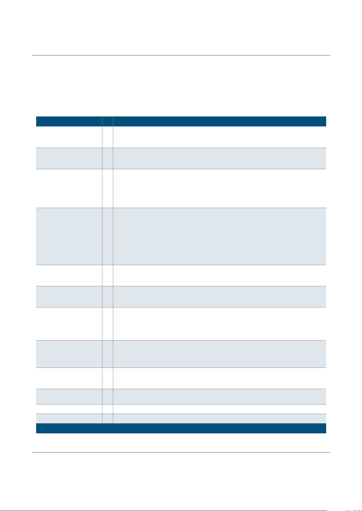
Table 1: Internal Interface Signal Descriptions
Signal I/O Description
Usr_Addr_WrData[31:0] O
T arget address, and data from target writes. During all target accesses, the address will be presented
on Usr_Addr_WrData[31:0] and simultaneously, Usr_Adr_Valid will be active. During target write
transactions, this port will also present write data to the PCI configuration space or user logic.
Usr_CBE[3:0] O
PCI command and byte enables. During target accesses, the PCI command will be presented on
Usr_CBE[3:0] and simultaneously, Usr_Adr_Valid will be active. During target read or write
transactions, this port will present active-low byte-enables to the PCI configuration space or user logic.
Usr_Adr_Valid O
Indicates the beginning of a PCI transaction, and that a target address is valid on
Usr_Addr_WrData[31:0] and the PCI command is valid on Usr_CBE[3:0]. When this signal is active,
the target address must be latched and decoded to determine if this address belongs to the device's
memory space. Also, the PCI command must be decoded to determine the type of PCI transaction.
On subsequent clocks of a target access, this signal will be low, indicating that an address is NOT
present on Usr_Addr_WrData[31:0].
Usr_Adr_Inc O
Indicates that the target address should be incremented, because the previous data transfer has
completed. During burst target accesses, the target address is only presented to the back-end logic
at the beginning of the transaction (when Usr_Adr_V alid is active), and m ust therefore be latched and
incremented (by 4) for subsequent data transfers. Note that during write transactions, Usr_Adr_Inc
indicates valid data on Usr_Addr_WrData[31:0] that must be accepted by the back-end logic
(regardless of the state of Usr_Rdy). During read transactions, Usr_Adr_Inc will signal to the back-end
that the PCI core is ready to accept data. Usr_Adr_Inc and Usr_Rdy both active during a read
transaction signals a data transfer between the FPGA and the PCI core (and that the address counter
must be incremented).
Usr_RdDecode I
This signal should be driven active when a "user read" command has been decoded from the
Usr_CBE[3:0] bus (while Usr_Adr_Valid is activ e). This command may be mapped from any of the PCI
"read" commands, such as Memory Read, Memory Read Line, Memory Read Multiple, I/O Read, etc.
Usr_WrDecode I
This signal should be driven active when a "user write" command has been decoded from the
Usr_CBE[3:0] bus (while Usr_Adr_Valid is activ e). This command may be mapped from any of the PCI
"write" commands, such as Memory Write or I/O Write.
Usr_Select I
This signal should be driven active when the address on Usr_Addr_WrData[31:0] has been decoded
and determined to be within the address space of the device. Usr_Addr_WrData[31:0] must be
compared to each of the valid Base Address Registers in the PCI configuration space. Also, this signal
must be gated by the Memory Access Enable or I/O Access Enable registers in the PCI configuration
space (Command Register bits 1 or 0 at offset 04h).
Usr_Write O
This signal will be active throughout a "user write" transaction, which has been decoded by
Usr_WrDecode at the beginning of the transaction. The write-enable for individual double-words of
data (on Usr_Addr_WrData[31:0]) during a user write transaction should be generated by logically
ANDing this signal with Usr_Adr_Inc.
Cfg_Write O
This signal will be active throughout a configuration write transaction. The write-enable for individual
double-words of data (on Usr_Addr_WrData[31:0]) during a configuration write transaction should be
generated by logically ANDing this signal with Usr_Adr_Inc.
Cfg_RdData[31:0] I
Data from the PCI configuration registers, required to be presented to the PCI core during PCI
configuration reads.
Usr_RdData[31:0] I Data from the back-end user logic, required to be presented during PCI reads.
Cfg_CmdReg8Cfg_CmdReg6 I Bits 6 and 8 from the Command Register in the PCI configuration space (offset 04h).
(Sheet 1 of 2)

6
www.quicklogic.com
© 2002 QuickLogic Corporation
•
•
•
•
•
•
QL5030 QuickPCI Data Sheet
Cfg_PERR_Det O
Parity error detected on the PCI bus. When this signal is activ e , bit 15 of the Status Register must be
set in the PCI configuration space (offset 04h).
Cfg_SERR_Sig O
System error asserted on the PCI bus. When this signal is active, the Signaled System Error bit, bit
14 of the Status Register, must be set in the PCI configuration space (offset 04h).
Usr_TRDYN O Copy of the TRDYN signal as driven by the PCI target interface.
Usr_STOPN O Copy of the STOPN signal as driven by the PCI target interface.
Usr_Devsel O Inverted copy of the DEVSELN signal as driven by the PCI target interface.
Usr_Last_Cycle_D1 O Indicates that the last transfer in a PCI transaction is occurring.
RdPipe_Stat[1:0] O
Indicates the number of dwords currently in the read pipeline ("00" = 0 elements, "01" = 1 element,
"11" = 2 elements). This value is important at the end of a transaction (i.e. when Usr_Last_Cycle_D1
is active) if non-prefetchable memory is being read. Non-prefetchable memory is defined as registers
or memory elements whose value changes when they are read. Examples are status registers which
are cleared when they are read, or FIFO memories, since consecutive reads from the same address
in these elements may not produce the same data values.
Usr_Rdy I
Used to delay (add wait states to) a PCI transaction when the back end needs additional time. Subject
to PCI latency restrictions.
Usr_Stop I Used to prematurely stop a PCI target access on the next PCI clock.
Table 1: Internal Interface Signal Descriptio ns (Continued)
Signal I/O Description
(Sheet 2 of 2)

QL5030 QuickPCI Data Sheet Rev C
7
•
•
•
•
•
•
QL5030 QuickPCI Data Sheet
6.0 Array of Logic Cells
A wide range of additional features complements the QL5030 device. The FPGA portion of the device
is 5-volt and 3.3-volt PCI-compliant and can perform high-speed logic functions such as 160 MHz
FIFOs. I/O pins provide individually controlled output enables, dedicated input/feedback registers, and
full JTAG capability for boundary scan and test. In addition, the QL5030 device provides the benefits of
non-volatility, high design security, immediate functionality on power-up, and a single chip solution.
The QL5030 programmable logic architecture consists of an array of user-configurable logic building
blocks, called logic cells, set beneath a grid of metal wiring channels similar to those of a gate array.
Through ViaLink® elements located at the wire intersections, the output(s) of any cell may be
programmed to connect to the input(s) of any other cell. Using the programmable logic in the QL5030,
designers can quickly and easily customize their “back-end” design for any number of applications.
Figure 4: Logic Cell
A1
A2
A3
A4
A5
A6
OS
OP
B1
B2
C1
C2
MP
MS
D1
D2
E1
E2
NP
NS
F1
F2
F3
F4
F5
F6
QC
QR
QS
AZ
OZ
QZ
NZ
FZ

8
www.quicklogic.com
© 2002 QuickLogic Corporation
•
•
•
•
•
•
QL5030 QuickPCI Data Sheet
7.0 RAM Module Features
The QL5030 device has eight 1,152-bit RAM modules, for a total of 9,216 RAM bits. Using two
“mode” pins, designers can configure each module into 64 (deep) x18 (wide), 128x9, 256x4, or 512x2
blocks. See Figure 5. The blocks are also easily cascadable to increase their effective width or depth.
Figure 5: RAM Module
The RAM modules are “dual-ported”, with completely independent READ and WRITE ports and
separate READ and WRITE clocks. The READ ports support asynchronous and synchronous operation,
while the WRITE ports support synchronous operation. Each port has 18 data lines and 9 address lines,
allowing word lengths of up to 18 bits and address spaces of up to 512 words. Depending on the mode
selected, however, some higher order data or address lines may not be used.
The Write Enable (WE) line acts as a clock enable for synchronous write operation. The Read Enable
(RE) acts as a clock enable for synchronous READ operation (ASYNCRD input low), or as a flow-through
enable for asynchronous READ operation (ASYNCRD input high).
Designers can cascade multiple RAM modules to increase the depth or width allowed in single modules
by connecting corresponding address lines together and dividing the words between modules. This
approach allows up to 512-deep configurations as large as 16 bits wide in the QL5030 device.
A similar technique can be used to create depths greater than 512 words. In this case, address signals
higher than the eighth bit are encoded onto the write enable (WE) input for WRITE operations. The
READ data outputs are multiplexed together using encoded higher READ address bits for the multiplexer
SELECT signals.
Table 2: RAM Mode
Mode: Address Buses [a:0] Data Buses [w:0]
64x18 [5:0] [17:0]
128x9 [6:0] [8:0]
256x4 [7:0] [3:0]
512x2 [8:0] [1:0]
MODE[1:0]
WA[a:0]
WD[w:0]
WE
WCLK
RAM Module
ASYNCRD
RA[a:0]
RD[w:0]
RE
RCLK

QL5030 QuickPCI Data Sheet Rev C
9
•
•
•
•
•
•
QL5030 QuickPCI Data Sheet
8.0 JTAG Support
JTAG pins support IEEE standard 1149.1a to provide boundary scan capability for the QL5030 device.
Six pins are dedicated to JTAG and programming functions on each QL5030 device, and are unavailable
for general design input and output signals. TDI, TDO, TCK, TMS, and TRSTB are JTAG pins. A sixth
pin, STM, is used only for programming.
9.0 Development Tools
Software support for the QL5030 device is available through the QuickWorksTM development package.
This turnkey PC-based QuickWorks package, shown in Figure 6, provides a complete ESP software
solution with design entry, logic synthesis, place and route, and simulation. QuickWorks includes VHDL,
Verilog, schematic, and mixed-mode entry with fast and efficient logic synthesis provided by the
integrated Synplicity Synplify Lite
TM
tool, specially tuned to take advantage of the QL5030 architecture.
QuickWorks also provides functional and timing simulation for guaranteed timing and source-level
debugging.
The UNIX-based QuickTools
TM
and PC-based QuickWorks-LiteTM packages are a subset of QuickWorks
and provide a solution for designers who use schematic-only design flow third-party tools for design
entry, synthesis, or simulation. QuickTools and QuickWorks-Lite read EDIF netlists and provide support
for all QuickLogic devices. QuickTools and QuickWorks-Lite also support a wide range of third-party
modeling and simulation tools. In addition, the PC-based package combines all the features of
QuickWorks-Lite with the SCS schematic capture environment, providing a low-cost design entry and
compilation solution.
Figure 6: QuickWorks Tool Suite
Schematic
Schematic
Turbo Writer
HDL Editor
Third Party
Design
Entry
& Synthesis
Third Party
Simulation
VHDL/
VHDL/
Verilog
Verilog
SCS Schematic
Tools
Silos
Simulators
QuickTools/QuickChip:
Optimize, Place, &
Route
Mixed-Mode Design
Mixed-Mode Design
Synplify-Lite
HDL
Synthesis
QuickWorks Design Software
&

10
www.quicklogic.com
© 2002 QuickLogic Corporation
•
•
•
•
•
•
QL5030 QuickPCI Data Sheet
10.0 DC Characteristics
The DC Specifications are provided in the tables below.
Table 3: Absolute Maximum Ratings
VCC Voltage
-0.5 to 4.6V
DC Input Current
±20 mA
V
CCIO
Voltage
-0.5 to 7.0V
ESD Pad Protection
±2000V
Input Voltage
-0.5V to V
CCIO
+0.5V
Storage Temperature
-65°C to +150°C
Latch-up Immunity
±200 mA
Lead Temperature
300°C
Table 4: Operating Range
Symbol Parameter Industrial Commercial Unit
Min Max Min Max
V
CC
Supply Voltage 3.0 3.6 3.0 3.6 V
V
CCIO
I/O Input Tolerance Voltage 3.0 5.5 3.0 5.25 V
TA Ambient Temperature -40 85 0 70 °C
K Delay Factor -A Speed Grade 0.43 0.90 0.46 0.88
Table 5: DC Characteristics
Symbol Parameter Conditions Min Max Unit
VIH Input HIGH Voltage 0.5VCC VCCIO+0.5 V
VIL Input LOW Voltage -0.5 0.3VCC V
VOH Output HIGH Voltage
IOH = -12 mA 2.4 V
IOH = -500 mA 0.9VCC V
VOL Output LOW Voltage
IOL = 16 mA 0.45 V
IOL = 1.5 mA 0.1VCC V
II I or I/O Input Leakage Current VI = VCCIO or GND -10 10 mA
IOZ 3-State Output Leakage Current VI = VCCIO or GND -10 10 mA
CI Input Capacitance [a]
a. Capacitance is sample tested only.
10 pF
IOS Output Short Circuit Current [b]
b. Only one output at a time. Duration should not exceed 30 seconds.
VO = GND -15 -180 mA
VO = VCC 40 210 mA
ICC D.C. Supply Current [c]
c. See Application Note 32: Power calculations for QuickLogic devices.
VI, VIO = VCCIO or GND 0.50 (typ) 2 mA
ICCIO D.C. Supply Current on VCCIO 0 100 mA

QL5030 QuickPCI Data Sheet Rev C
11
•
•
•
•
•
•
QL5030 QuickPCI Data Sheet
11.0 AC CHARACTERISTICS at VCC = 3.3V, TA = 25×C (K = 1.00)
To calculate delays, multiply the appropriate K factor in the “Operating Range” section by the following
numbers.
Table 6: Logic Cells
Symbol Parameter
Propagation Delays (ns)
Fanout [a]
a. These limits are derived from a representative selection of th e slowest paths through the Quick-
RAM logic cell including typical net delays. Worst case delay values for specific paths should be
determined from timing analysis of your particular design.
1 2 3 4 8
tPD Combinatorial Delay 1.4 1.7 1.9 2.2 3.2
tSU Setup Time 1.7 1.7 1.7 1.7 1.7
tH Hold Time 0.0 0.0 0.0 0.0 0.0
tCLK Clock to Q Delay 0.7 1.0 1.2 1.5 2.5
tCWHI Clock High Time 1.2 1.2 1.2 1.2 1.2
tCWLO Clock Low Time 1.2 1.2 1.2 1.2 1.2
tSET Set Delay 1.0 1.3 1.5 1.8 2.8
tRESET Reset Delay 0.8 1.1 1.3 1.6 2.6
tSW Set Width 1.9 1.9 1.9 1.9 1.9
tRW Reset Width 1.8 1.8 1.8 1.8 1.8
Table 7: RAM Cell Synchronous Write Timi ng
Symbol Parameter
Propagation Delays (ns)
Fanout [a]
a. Stated timing for worst case Propagation Delay over process variation at VCC=3.3V and TA=25×C.
Multiply by the appropriate Delay Factor, K, for speed grade, voltage and temperature settings as
specified in the Operating Range.
1 2 3 4 8
tSWA WA Setup Time to WCLK 1.0 1.0 1.0 1.0 1.0
tHWA WA Hold Time to WCLK 0.0 0.0 0.0 0.0 0.0
tSWD WD Setup Time to WCLK 1.0 1.0 1.0 1.0 1.0
tHWD WD Hold Time to WCLK 0.0 0.0 0.0 0.0 0.0
tSWE WE Setup Time to WCLK 1.0 1.0 1.0 1.0 1.0
tHWE WE Hold Time to WCLK 0.0 0.0 0.0 0.0 0.0
tWCRD WCLK to RD (WA=RA) [4] 5.0 5.3 5.6 5.9 7.1

12
www.quicklogic.com
© 2002 QuickLogic Corporation
•
•
•
•
•
•
QL5030 QuickPCI Data Sheet
Table 8: RAM Cell Synchronous Read Timing
Symbol Parameter
Propagation Delays (ns)
Fanout
1 2 3 4 8
tSRA RA Setup Time to RCLK 1.0 1.0 1.0 1.0 1.0
tHRA RA Hold Time to RCLK 0.0 0.0 0.0 0.0 0.0
tSRE RE Setup Time to RCLK 1.0 1.0 1.0 1.0 1.0
tHRE RE Hold Time to RCLK 0.0 0.0 0.0 0.0 0.0
tRCRD RCLK to RD [5] 4.0 4.3 4.6 4.9 6.1
Table 9: RAM Cell Asynchronous Read Timing
Symbol Parameter
Propagation Delays (ns)
Fanout
1 2 3 4 8
rPDRD RA to RD [5] 3.0 3.3 3.6 3.9 5.1
Table 10: Input-Only Cells
Symbol Parameter
Propagation Delays (ns)
Fanout [a]
a. These limits are derived from a representative selection of th e slowest paths through the Quick-
RAM logic cell including typical net delays. Worst case delay values for specific p aths should be
determined from timing analysis of your particular design.
1 2 3 4 8 12 24
tIN High Drive Input Delay 1.5 1.6 1.8 1.9 2.4 2.9 4.4
tINI High Drive Input, Inverting Delay 1.6 1.7 1.9 2.0 2.5 3.0 4.5
tISU Input Register Set-Up Time 3.1 3.1 3.1 3.1 3.1 3.1 3.1
tIH Input Register Hold Time 0.0 0.0 0.0 0.0 0.0 0.0 0.0
tlCLK Input Register Clock To Q 0.7 0.8 1.0 1.1 1.6 2.1 3.6
tlRST Input Register Reset Delay 0.6 0.7 0.9 1.0 1.5 2.0 3.5
tlESU Input Register Clock Enable Setup Time 2.3 2.3 2.3 2.3 2.3 2.3 2.3
tlEH Input Register Clock Enable Hold Time 0.0 0.0 0.0 0.0 0.0 0.0 0.0

QL5030 QuickPCI Data Sheet Rev C
13
•
•
•
•
•
•
QL5030 QuickPCI Data Sheet
Table 11: Clock Cells
Symbols Parameter
Propagation Delays (ns)
Loads per Half Column [a]
a. The array distributed networks consist of 40 half columns and the global distributed networks con-
sist of 44 half columns, each driven by an indepen dent buffer. The number of h alf columns used
does not affect clock buffer delay. The array clock has up to 8 loads per half column. The global
clock has up to 11 loads per half column.
1 2 3 4 8 10 12 15
tACK Array Clock Delay 1.2 1.2 1.3 1.3 1.5 1.6 1.7 1.8
tGCKP Global Clock Pin Delay 0.7 0.7 0.7 0.7 0.7 0.7 0.7 0.7
tGCKB Global Clock Buffer Delay 0 .8 0.8 0.9 0.9 1.1 1.2 1.3 1.4
Table 12: I/O Cell Input Delays
Symbol Parameter
Propagation Delays (ns)
Fanout [5]
1 2 3 4 8 10
tI/O Input Delay (bidirectional pad) 1.3 1.6 1.8 2.1 3.1 3.6
tISU Input Register Set-Up Time 3.1 3.1 3.1 3.1 3.1 3.1
tIH Input Register Hold Time 0.0 0.0 0.0 0.0 0.0 0.0
tlOCLK Input Register Clock To Q 0.7 1.0 1.2 1.5 2.5 3.0
tlORST Input Register Reset Delay 0.6 0.9 1.1 1.4 2.4 2.9
tlESU Input Register clock Enable Set-Up Time 2.3 2.3 2.3 2.3 2.3 2.3
tlEH Input Register Clock Enable Hold Time 0.0 0.0 0.0 0.0 0.0 0.0

14
www.quicklogic.com
© 2002 QuickLogic Corporation
•
•
•
•
•
•
QL5030 QuickPCI Data Sheet
NOTE:
The following loads are used for tPXZ:
Table 13: I/O Cell Output Delays
Symbol Parameter
Propagation Delays (ns)
Output Load Capacitance (pF)
30 50 75 100 150
tOUTLH Output Delay Low to High 2.1 2.5 3.1 3.6 4.7
tOUTHL Output Delay High to Low 2.2 2.6 3.2 3.7 4.8
tPZH Output Delay Tri-state to High 1.2 1.7 2.2 2.8 3.9
tPZL Output Delay Tri-state to Low 1.6 2.0 2.6 3.1 4.2
tPHZ Output Delay High to Tri-State 2.0
tPLZ Output Delay Low to Tri-State 1.2
5 pF
1KΩ
5 pF
1KΩ
tPHZ
tPLZ

QL5030 QuickPCI Data Sheet Rev C
15
•
•
•
•
•
•
QL5030 QuickPCI Data Sheet
12.0 QL5030 External Device Pins
The QL5030 Device Pins are indicated in Tabl e 14 and Tabl e 15 below. These are pins on the device,
some of which connect to the PCI bus, and others that are programmable as user I/O.
NOTE:
*See QuickNote 65 on the QuickLogic website for information on RAM initialization.
Table 14: Pin Type Descriptions
Type Description
IN Input. A standard input-only signal
OUT Totem pole output. A standard active output driver
T/S Tri-state. A bi-directional, tri-state input/output pin
S/T/S
Sustained Tri-state. An active low tri-state signal driven by one PCI agent at a time. It must be driven
high for at least one clock before being disabled (set to Hi-Z). A pull-up needs to be provided by the
PCI system central resource to sustain the inactive state once the active driver has released the
signal.
O/D Open Drain. Allows multiple devices to share this pin as a wired-or.
Table 15: Device Pins
Pin/Bus Name Type Function
VCC IN Supply pin. Tie to 3.3V supply.
VCCIO IN Supply pin for I/O. Set to 3.3V for 3.3V I/O, 5V for 5.0V compliant I/O
GND IN Ground pin. Tie to GND on the PCB.
I/O T/S Programmable Input/Output/Tri-State/Bi-directional Pin.
GLCK/I IN Programmable Global Network or Input-only pin. Tie to VCC or GND if unused.
ACLK/I IN Programmable Array Network or Input-only pin. Tie to VCC or GND if unused.
TDI/RSI* IN
JTAG Data In/Ram Init. Serial Data In. Tie to VCC if unused. Connect to Serial
EPROM data for RAM init.
TDO/RCO* OUT
JTAG Data Out/Ram Init Clock. Leave unconnected if unused. Connect to Serial
EPROM clock for RAM init.
TCK IN JTAG Clock. Tie to GND if unused.
TMS IN JTAG Test Mode Select. Tie to VCC if unused.
TRSTB/RRO
* IN
JT AG Reset/RAM Init. Reset Out. Tie to GND if unused. Connect to Serial EPROM
reset for RAM init.
STM IN QuickLogic Reserved pin. Tie to GND on the PCB.

16
www.quicklogic.com
© 2002 QuickLogic Corporation
•
•
•
•
•
•
QL5030 QuickPCI Data Sheet
13.0 External Device Pins
14.0 Ordering Information
Table 16: External Device Pins
Pin/Bus Name Type Function
AD[31:0] T/S PCI Address and Data: 32 bit multiplexed address/data bus.
CBEN[3:0] T/S
PCI Bus Command and Byte Enables: Multiplexed bus which contains byte enables for AD[31:0] or
the Bus Command during the address phase of a PCI transaction.
PAR T/S
PCI Parity: Even Parity across AD[31:0] and C/BEN[3:0] busses. Driven one clock after address or
data phases. Master drives PAR on address cycles and PCI writes. The Target drives PAR on PCI
reads.
FRAMEN S/T/S
PCI Cycle Frame: Driven activ e by current PCI Master during a PCI transaction. Driven low to indicate
the address cycle, driven high at the end of the transaction.
DEVSELN S/T/S PCI Device Select. Driven by a Target that has decoded a valid base address.
CLK IN PCI System Clock Input.
RSTN IN PCI System Reset Input
PERRN S/T/S
PCI Data Parity Error. Driven active by the initiator or target two clock cycles after a data parity error
is detected on the AD and C/BEN busses.
SERRN O/D
PCI System Error: Driven active when an address cycle parity error, data parity error during a special
cycle, or other catastrophic error is detected.
IDSEL IN PCI Initialization Device Select. Use to select a specific PCI Agent during System Initialization.
IRDYN S/T/S
PCI Initiator Ready . Indicates the Initiator’s ability to complete a read or write transaction. Data transfer
occurs only on clock cycles where both IRDYN and TRDYN are active.
TRDYN S/T/S
PCI Target Ready. Indicates the Target’s ability to complete a read or write transaction. Data transfer
occurs only on clock cycles where both IRDYN and TRDYN are active.
STOPN S/T/S PCI Stop. Used by a PCI Target to end a burst transaction.
QL 5030 - 4 TQ144 C
QuickLogic device
QuickPCI device
part number
Speed Grade
4 = Quick
Operating Range
C = Commercial
I = Industrial
Package Code
TQ144 = 144-pin TQFP

QL5030 QuickPCI Data Sheet Rev C
17
•
•
•
•
•
•
QL5030 QuickPCI Data Sheet
15.0 144 TQFP Pinout Diagram
16.0 144 TQFP Pinout Table
Table 17: 144 TQFP Pinout Table
PF144 Function PF144 Function PF144 Function PF144 Function
1 I/O 37 AD[21] 73 AD[4] 109 TCK
2 I/O 38 TDI/RSI 74 AD[3] 110 STM
3 I/O 39 AD[20] 75 AD[2] 111 I/O
4 I/O 40 AD[19] 76 AD[1] 112 I/O
5 I/O 41 AD[18] 77 AD[0] 113 I/O
6 I/O 42 VCC 78 I/O 114 VCC
7 VCC 43 AD[17] 79 VCC 115 I/O
8 I/O 44 AD[16] 80 I/O 116 I/O
9 I/O 45 CBEN[2] 81 I/O 117 I/O
10 I/O 46 FRAMEN 82 I/O 118 I/O
11 I/O 47 IRDYN 83 I/O 119 I/O
12 I/O 48 TRDYN 84 I/O 120 I/O
13 I/O 49 DEVSELN 85 I/O 121 I/O
14 I/O 50 GND 86 I/O 122 GND
15 GND 51 STOPN 87 GND 123 I/O
16 I/O 52 PERRN 88 I/O 124 I/O
17 GCLK/I 53 SERRN 89 GCLK/I 125 I/O
18 ACLK/I 54 GND 90 ACLK/I 126 GND
19 VCC 55 PAR 91 VCC 127 I/O
20 RSTN 56 CBEN[1] 92 GCLK/I 128 I/O
21 CLK 57 AD[15] 93 GCLK/I 129 I/O
22 VCC 58 VCCIO 94 VCC 130 VCCIO
23 I/O 59 AD[14] 95 I/O 131 I/O
24 AD[31] 60 AD[13] 96 I/O 132 I/O
25 AD[30] 61 AD[12] 97 I/O 133 I/O
26 AD[29] 62 AD[11] 98 I/O 134 I/O
27 AD[28] 63 AD[10] 99 I/O 135 I/O
28 AD[27] 64 AD[9] 100 I/O 136 I/O
29 AD[26] 65 AD[8] 101 I/O 137 I/O
30 GND 66 GND 102 GND 138 GND
31 AD[25] 67 CBEN[0] 103 I/O 139 I/O
32 AD[24] 68 AD[7] 104 I/O 140 I/O
33 CBEN[3] 69 AD[6] 105 I/O 141 I/O
34 IDSEL 70 AD[5] 106 I/O 142 I/O
35 AD[23] 71 TRSTB/RRO 107 I/O 143 TDO/RCO
36 AD[22] 72 TMS 108 I/O 144 I/O
QuickPCI
QL5030-33APF144C
PIN #109
PIN #73
PIN #37
PIN #1

18
www.quicklogic.com
© 2002 QuickLogic Corporation
•
•
•
•
•
•
QL5030 QuickPCI Data Sheet
17.0 Revision History
Copyright © 2002 QuickLogic Corporation.
All Rights Reserved.
The information contained in this product brief, and the accompanying software programs are protected by
copyright. All rights are reserved by QuickLogic Corporation. QuickLogic Corporation reserves the right to make
periodic modifications of this product without obligation to notify any person or entity of such revision. Copying,
duplicating, selling, or otherwise distributing any part of this product without the prior written consent of an
authorized representative of QuickLogic is prohibited.
QuickLogic, pASIC, and ViaLink are registered trademarks, and SpDE and QuickWor ks are trademarks of
QuickLogic Corporation.
Verilog is a registered trademark of Cadence Design Systems, Inc.
Table 18: Revision History
Revision Date Comments
A Sept 1999 First release.
B March 2001 Update of electrical specs
C Jan 2002 Re-formatted and re-organized for better clarity
 Loading...