

Page 1
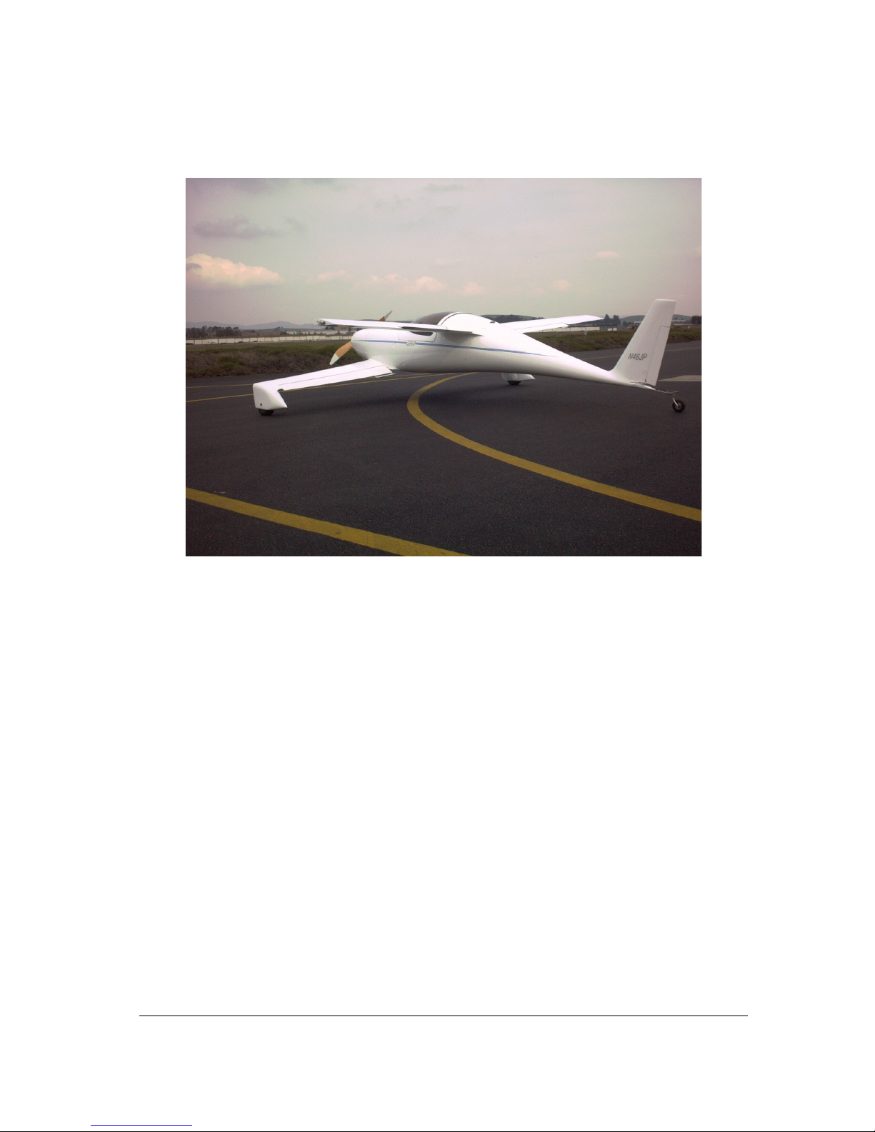
Q2 Quickie Construction Manual
The QUICKIE Q2 kit, properly constructed, will reproduce the successful
original QUICKIE Q2 designed, and tested by QUICKIE AIRCRAFT CORPORATION.
QUICKIE AIRCRAFT CORPORATION is not responsible, and makes no warranties,
express or implied whatsoever, regarding the structural integrity,
performance, flight characteristics, or safety of the Buyer's completed
aircraft and its component parts. QUICKIE AIRCRAFT CORPORATION has no control
and assumes no control over the Buyer's ability to successfully construct and
test the QUICKIE Q2 AIRCRAFT. Buyer expressly waives any and all claims
arising from structural integrity, performance, flight characteristics,
mechanical failures, and safety against QUICKIE AIRCRAFT CORPORATION. Buyer
acknowledges awareness of the risks of flying a homebuilt aircraft. Buyer
acknowledges that the FAA must inspect the aircraft at construction intervals,
as well as the completed project, prior to flight and should work with his
local FAA representative regarding the construction and licensing of the
aircraft.
..
QUICKIE AIRCRAFT CORPORATION reserves the right to make recommended revisions
in the plans and construction of the aircraft at any time without liability to
QUICKIE AIRCRAFT CORPORATION, as such revisions or changes may be deemed
advisable from time to time.
Page 2

Q2 Plans – Appendix Page i
TABLE OF CONTENTS
CHAPTER TITLE NO. OF PAGES NO. OF SHEETS
1 DESCRIPTION AND INTRODUCTION 3 2
2 BILL OF MATERIALS 1 1
3 COMPOSITE MATERIALS EDUCATION 23 12
4 INDIVIDUAL PART CONSTRUCTION 2 1
5 HOT-WIRING 4 2
6
7 VERTICAL FIN CONSTRUCTION 2 1
8 BASIC FUSELAGE ASSEMBLY 5 3
9 MAIN WING CONSTRUCTION 9 5
10 CANARD CONSTRUCTION 10 5
11
12 MAIN WING AND CANARD MOUNTING 3 2
AILERONS, RUDDER, AND
ELEVATORS CONSTRUCTION
WHEEL PANT/TIRE/WHEEL/BRAKE
ASSEMBLY
SECTION I
3 2
6 3
13 CANOPY ASSEMBLY AND MOUNTING 4 2
14 FUSELAGE DETAIL ASSEMBLY 10 5
- APPENDIX SHEETS 1 THRU 6 6 6
SECTION II
15 MAKING YOUR Q2 TRAILERABLE 2 1
16 ENGINE INSTALLATION 6 3
17 FUEL SYSTEM INSTALLATION 3 2
18
19 ELECTRICAL SYSTEM 1 1
20 COMPLETING YOUR Q2 5 3
INSTRUMENT AND PITOT-STATIC
SYSTEM INSTALLATION
1 1
Page 3

ADDITIONAL Q2 DOCUMENTATION
TITLE
CONTENTS
DATE OF
FIRST
PUBLICATION
Q2 Pilot's Manual
Quickie Newsletter Published quarterly (Jan, April, July,
Q2 Information
Package
Quickie & 'Q2
Composite Materials
Introductory
Package
Flight and maintenance manual includes
normal and emergency procedures, weight
and balance, check lists, detailed flying
qualities descriptions, operating
limitations, performance charts, first
flight test procedures, pilot checkout
procedures, and systems descriptions.
and October); includes plans changes,
builder tips, options, current and future
developments, and dates and information
on future seminars.
Provides general information on the Q2,
including performance, construction
techniques, and a poster.
Provides an education in the techniques
required in the building of a Q2.
Includes a booklet, and sufficient
materials for several suggested projects.
Somewhat redundant with Chapter 3 of the
Q2 Construction Plans.
1 May, 1981
25 May, 1978
9 February,
1981
8 April,
1981
Q2 Plans - Appendix Page ii
Q2 PLANS ADDENDUM
Page 4

Q2 Builder Tip Notices (Q2BT9) are intended to provide clarification,
guidance, improved construction methods, and helpful hints of a nonmandatory nature. The builder, at his discretion may use or discard
any Q2BT. Most are a result of work accomplished at Quickie Aircraft
Corporation building a Q2 from the Q2 Construction Plans. Any
questions on a Q2BT notice should be referred to Quickie Aircraft
Corporation. Each Q2BT has a number and a publication date along with
a description of the builder tip.
NUMBER DATE DESCRIPTION
Q2BT9
1 July, 1981 Q2 CONSTRUCTION PLANS -
SECTION I: Some plan sets sent
out may have faint reproduction on parts of pages
9-8, 10-1, 10-2, 10-3, 11-4,
14-2, and Appendix Sheet 4. We
intend to have those sections
reprinted within 30 days. We
will send the reprinted sheets
to any builder who reports
this problem.
Q2 Plans Change Notices (Q2PC9 & Q2PC10) are mandatory revisions to
the Q2 plans. Each Q2PC has a number and a publication date along
with a description of the change. All Q2PC notices should be
incorporated into the builder's set of Q2 Construction Plans
immediately upon receipt by the builder. Any questions on a Q2PC
notice should be referred to Quickie Aircraft Corp.
NUMBER DATE DESCRIPTION
Q2PC9
1 July, 1981 Q2 GROUND ANGLE OF ATTACK:
With the aircraft assembled
and WL15 level, and with the
aircraft on a reasonable level
floor, take a measurement
vertically between the floor
and the bottom of the
tailwheel. The nominal
measurement should be 27". A
range from 25" to 28.6" should
be Acceptable. This limitation
is to assist tailwheel first
landings and
three point takeoffs at
mid/forward c.g. Small change
can be effected by changing
the tailwheel diameter. It is
a good idea to delay mounting
the tailspring until the
aircraft is assembled, so that
Page 5
the proper height can be
achieved.
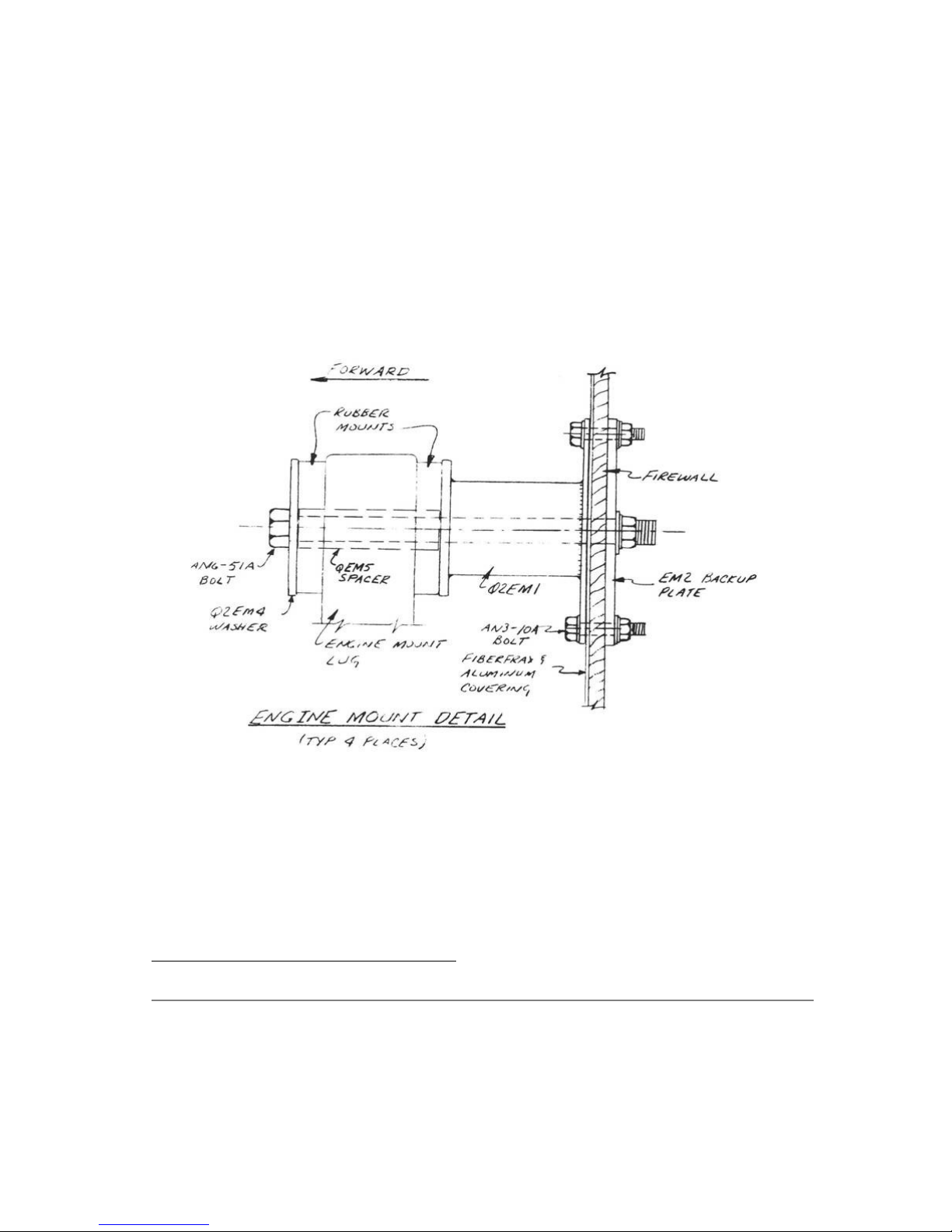
Q2PC10
1 July, 1981 ENGINE MOUNT INSTALLATION, P-
16-2 does not indicate the
required spacer. The material
is 4130 steel, or mild steel
of 1/2" 0.0. x 3/8" 1.0. The
sketch indicates the location
of this QEM5 spacer (4
required).
Q2 Plans - Appendix Page iii
NUMBER DATE DESCRIPTION
ii
Page 6

Q2BT11
21 August,
1981
MASS BALANCING ELEVATORS. In
preparation for testing on
turbocharged Revmasters and
possible A-65 thru C-85
installations, we have further
explored the very high speed area
of the Q2 operating envelope. We
have found that mass balancing the
elevators improves the ride
qualities at high speed. Therefore,
we are supplying to all builders
the drawings and hardware to mass
balance all Q2 elevators, and
recommend this before first flight.
See pages...for details.
ELEVATOR MASS BALANCING
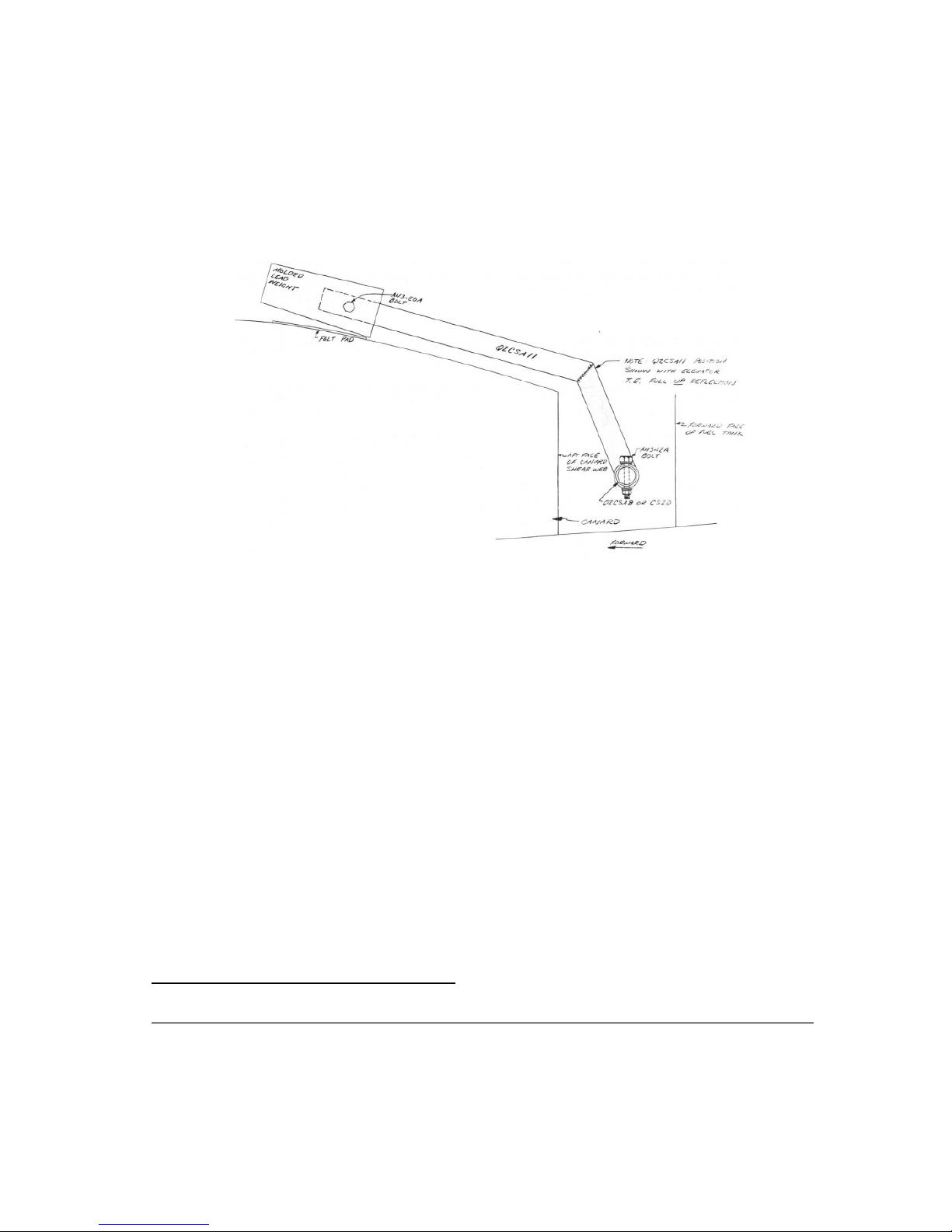
.....Locate the two Q2CSA11 arms and the molded lead weights.
.....These elevator mass balance arms can be retrofitted to the elevator
control system even after the canard has been mounted to the fuselage.
This will allow a closer clearance with the fuselage sides and maximize
the available legroom. If the mass balance arms are installed prior to
mounting the canard, careful measurements must be made to assure
clearance with the fuselage sides.
.....Begin by attaching a molded lead weight to each Q2CSA11 as shown.
.....Next, remove the two bolts holding CS20 in position, and slide it
outboard through the CS14 phenolic bearing until a Q2CSA11 arm can be
slid onto the tube with the lead weight projecting forward. Reinstall the
bolts holding CS20 in position.
.....Then remove the three bolts securing Q2CSA8 and slip it inboard
until the second Q2CSA11 arm can be slid on the outboard end inward with
the lead weight projecting forward. Reinstall the bolts holding Q2CSA8 in
place.
.....Locate the Elevator Rigging template and jig the elevator in the
full trailing edge up position. With the elevator in this position, each
Q2CSA11 should be almost resting on the canard upper surface just inboard
of the fuselage. Note the piece of felt called out as a bumper stop. The
Q2CSA11's are located as far outboard as practical so as not to interfere
with pilot or passenger legroom. Verify that when the elevator is rotated
to full trailing edge down position, that the arc of each Q2CSA11 clears
the fuselage and all other components.
.....Finally, return the elevator to the full trailing edge up position
with each Q2CSA11 resting almost on the canard, and drill in the one AN312A bolt per side to attach the Q2CSA11's to Q2CSA8 and CS20.
.....Leave the CS13 pitch control arm unattached from Q2CSA8, and remove
the two AN4-11A bolts attaching the universal joint to Q2CSA8 and CS20.
Remove the universal joint so that each elevator can rotate independently
of the other. Make sure that you have lubricated all of the bearing and
hinge points to reduce the system friction to a minimum. It is desirable
for each elevator to balance at 0 degrees to 2 degrees trailing edge up
with all painting and finishing complete. Remove lead, as necessary from
the molded lead weight until that position is reached. Each elevator
should rotate freely about the hinge points when given a slight nudge.
Page 7
Failure of this check means that the pivots are too tight and must be
adjusted for minimum friction.
.....Once the amount of lead weight on each elevator has been adjusted,
bolt the entire pitch control system together and check for friction,
excess play, and interferences.
iii
Q2 Plans - Appendix Page iv
NUMBER DATE DESCRIPTION
Page 8

Q2BT12
21 August, 1981 IMPROVED BRAKING EFFECTIVNESS. We
have determined that a single pull
brake handle modulating both main
gear brakes simultaneously is
superior in nearly all situations
to the standard toe brakes.
Materials and drawings are
available for retrofit for all
builders returning their unused
Q2BSW1's & two AN210-1A pullies to
QAC. Current kit shipments
incorporate this modification as
standard.
Development work continues on a
set of retrofittable hydraulic
disc brakes, which may be
available as early as October,
1981. Those builders not ready to
fly before then may wish to wait
and decide whether they wish to
retrofit that system instead.
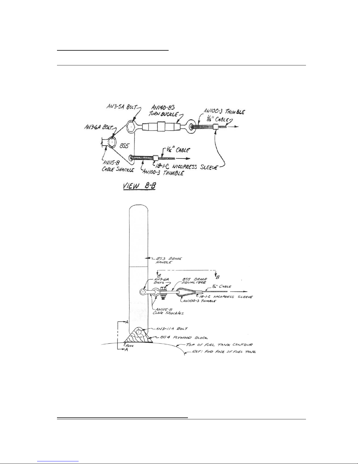
SINGLE PULL BRAKE HANDLE INSTALLATION
.....This section replaces the original section on installing the Brake
Pedals (Q2BSW1's) and four inboard pulleys. In place of the individually
controlled toe brakes, a single pull handle has been incorporated on the
left side of the cockpit.
.....Begin by fabricating BS3 and BS5 from the 0.125" thick Aluminum and
BS4 from 1/4" plywood.
(see next page for drawing)
Page 9
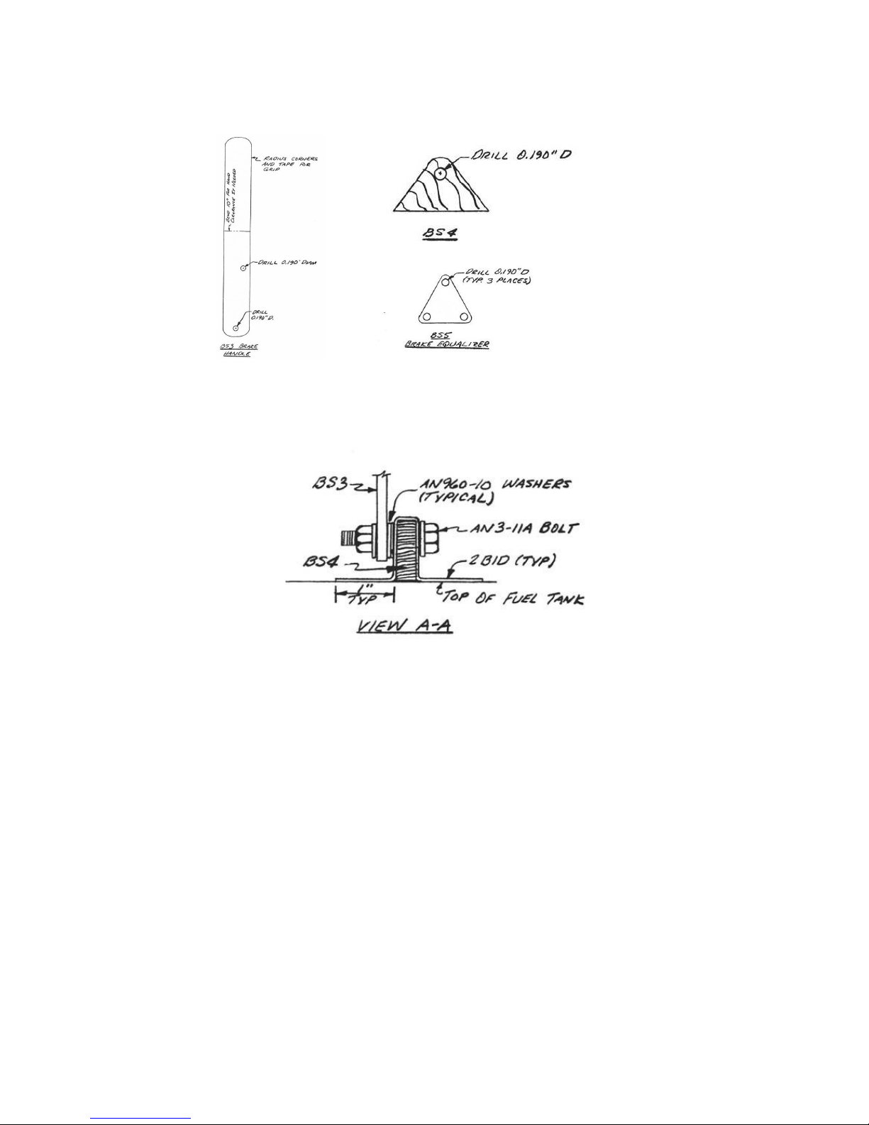
.....BS4
is mounted in position with flox and 2 BID tapes to the top of the fuel
tank near the left side console. Position the BS4 so that the handle
will be an easy and comfortable reach for the pilot and so it will not
interfere unnecessarily with pilot comfort.
.....Next, install the Brake Handle as shown in the sketch.
.....The Brake Equalizer is used to help proportion braking
effectiveness equally. The turnbuckle assembly on the left side must be
attached directly to BS5 because of the proximity of the cable to the
left elevator slot foam core. The turn buckle for the right side can be
mounted in the system outboard of the Canard shear web pulley.
The two BS3 Canard shear web pulley mounts shown on page 11-4 must be
modified in location for the proper angles.
The cable routing is from the BS5 Brake Equalizer around the two pulleys
on the canard shear web, and then outboard through the Elevator slot
foam cores as originally indicated.....
The turnbuckles are adjusted to provide equal braking on each wheel.
iv
Page 10
Q2 Plans - Appendix Page v
Q2 Plans - Chapter 1 - Page 1-1
Page 11

DESCRIPTION AND INTRODUCTION
DESCRIPTION AND INTRODUCTION: The Q2 is a high performance, homebuilt
aircraft. Its compact external size and extremely efficient design
results in superb performance and unequalled fuel economy using a low
horsepower engine. Inside, it provides side-by-side seating comfort
for a pilot up to 6'8" tall and 250 lbs, plus passenger, as well as
some baggage in the roomy compartment behind the seat. Its canard
configuration was designed not only for performance, but to provide
improved flying qualities and safety as compared to the conventional
light plane.
.....The origin of the Q2 dates back to 1977. Although the Q2 has
much in common with the QUICKIE, considerable progress has been made
since that earlier effort. As a result, the Q2 has lower drag than
any other two place aircraft available to the public. Likewise, it
has proven to be the most fuel efficient two-place aircraft ever
offered to the public.
.....The Q2's high-lift canard (forward wing) is fitted with a plain
elevator that controls the aircraft's pitch attitude. The canard also
serves as the main landing gear spring since the main gear is mounted
on the tips of the canard. This feature results in a remarkably
smooth ride as well as outstanding ground stability during taxiing,
takeoff, and landing.
.....Roll capability is provided by ailerons on the inboard position
of the main wing.
.....Yaw control is provided by a rudder mounted on the vertical fin,
and is actuated by conventional rudder pedals.
.....The pitch and roll capability is provided by a side stick
controller in the center of the cockpit. This feature permits precise
control of the Q2 while reducing pilot fatigue and cockpit clutter.
.....Optional dual controls provide the option of pilot checkout and
instruction.
.....The tail wheel is actuated directly from the rudder pedals,
without any springs, thus providing positive steering at all times
while on the ground.
.....Since the tail wheel is not raised on takeoff roll like other
tail draggers, this positive steering is available until the aircraft
is airborne, making for very safe takeoff and landing
characteristics.
.....Even though the Q2 has low horsepower, it can outperform most
general aviation aircraft while retaining unequalled fuel economy.
The maximum speed is actually faster than most retractable gear
aircraft, such as the Piper Arrow, and the fuel economy exceeds
60 miles per gallon.
.....The Q2 obtains this remarkable performance without resorting to
retractable landing gear, without flaps, without turbochargers, and
without variable pitch propellers.
.....Further, the Q2 was designed to be built by the inexperienced
builder, so these Q2 Construction Plans and the Q2 kit contents have
been developed for ease of construction. Construction time should
require only 500 man hours spread over less than one year of the
builders spare time, with no special tools required.
Page 12

.....The composite structure of your Q2 provides some important
advantages over conventional metal, wood, or fabric construction. It
has been tested to loads far in excess of those required for FAA
certification. Fatigue margins are higher. Contour is maintained
under load, the structure does not "oil can," buckle, or distort. It
provides excellent insulation and damps noise. It has no hidden
joints, no water traps, and is far less susceptible to corrosion.
It is easier to inspect, more redundant and easier to repair. It is
not susceptible to thermal stress due to temperature changes.
Properly protected from UV, it has an unlimited life.
Perspective
.....The builder of an amateur-built aircraft is the manufacturer; he
is responsible for quality control on all parts, all construction,
and the conduct of his flight tests. While Quickie Aircraft
Corporation is not the manufacturer of your aircraft, we do, through
these plans and services, provide you with information about how our
Q2 was built and what we feel is the best way for you to build a
safe, reliable airplane. We do encourage you. to build the airplane
as shown on the plans because we have found that our airplane
provides us with reliability and safety, and any problems that we
experience with our aircraft are documented and reported in "The
Quickie Newsletter". We have gone to a considerable effort in
developing the design, the structure, and the systems, and proving
their adequacy with appropriate tests.
.....If you modify the airplane and then ask us if your modification
will work, we cannot give you an answer without conducting the
appropriate tests and totally qualifying the modification. This would
obviously be quite expensive. Our concern then, is that if your
modification is not successful, and causes an incident or accident,
this would be attributed to our design, the Q2. Because of this, we
must insist that if you modify the airplane with any major change
such as an aerodynamic change, primary structural change, or using a
non-approved engine installation, that you call your airplane a
different name, rather than a Q2. If you make a major change, you
must consider yourself involved in basic aircraft design and
development, an extremely risky business. As such it is not fair for
us to be associated with any results of your development. We state
this, not to discourage inventiveness and progress, but to release
any connection of your new development efforts with our proven
design, the Q2.
.....We are particularly concerned about individuals using alternate
engines to power their Q2's. The Q2 was designed around the engine;
any change would require an exhaustive test program to determine not
only the new engine's suitability as an aircraft power plant, but
also its suitability as a Q2 power plant.
.....These Q2 Construction Plans have been specifically designed to
educate you in the construction materials, their use, and to guide
you through each step of assembly in the most efficient manner
possible. It is our intent to drastically reduce the non-completion
rate* common to homebuilt aircraft. With that in mind, we have:
1. Preceded the plans with an education section intended to
Page 13

thoroughly acquaint you with the tools and materials, and
how to use them.
2. Laid out the plans in a detailed, step-by-step format to
answer the questions of "what do I do next?"
3. Provided all appropriate information to each step
adjacent to the words.
4. Provided full-size templates, ready to cutout and use, to
avoid the work and confusion associated with scaling up
drawings.
5. Provided a complete kit from one source to eliminate time
spent looking for materials.
6. Identified the difficult to build items, and included
them (prefabricated and ready to install) with the basic
Q2 Kit.
7. Set up our newsletter, "The Quickie Newsletter" as a
continuing plans updating/correcting system.**
*..Over 80% of homebuilt airplane construction projects
started, are never finished and flown.
** Because plans updates occasionally are of a mandatory
nature, a subscription to "The Quickie Newsletter" is
mandatory for those building a Q2.
PAGE
1-1
Q2 Plans - Chapter 1 - Page 1-2
Page 14

Building Sequence
.....The nature of the Q2 structure requires that a part be left alone
to cure for a longer period of time than that required to build it.
Thus, you will find that when following the step-by-step order, you will
often find yourself out of work, waiting for a cure. In most cases you
can skip to another chapter and build another part while waiting. With a
little planning and familiarity with the entire manual, you should be
able to use all of your time productively.
Questions?
.....Please use the procedure detailed here if you do not understand
something and need an answer. First of all, do not be concerned if you
do not understand everything the first time you read through the plans.
Many things that may not be obvious just reading the drawings, will be
obvious when you have that portion of the airplane in front of you or
have built a similar part in a previous chapter. Also, we will be able
to help you better if you are looking at that portion of your airplane.
So, do not ask for clarification until you are really working-on that
particular chapter. We have found through our Quickie and Q2 experience
that the majority of questions that the homebuilder asks are already
answered somewhere in the plans. We have made considerable effort in the
Q2 Construction Plans to make the information visible. If you do not
understand something, study the words in the step, study the sketches
and all related sections/views/ photos, then look through the full size
drawings and components that show that portion of the airplane. If the
answer is still not found, it may be that the item is covered in detail
in another chapter (there is some necessary overlap). It is possible
that a question related to the operation of a part of the airplane or
its maintenance is answered in your Q2 Pilot's Manual. Also, check your
back issues of "The Quickie Newsletter" for plans updates or
clarifications. OK, if you have checked everything and you are still
stumped, you can do one of three things:
1. Ask a friend. Often a description of an item is unclear to one
individual and clear to another.
2. Write to Quickie Aircraft Corporation, leaving room on the paper
under each question for our answer. INCLUDE A SELF-ADDRESSED,
STAMPED ENVELOPE and INCLUDE YOUR AIRCRAFT SERIAL NUMBER. We do
our best to answer all such questions within two days of receipt.
We cannot answer questions regarding the application of non-
recommended materials or regarding non-approved modifications.
Quickie Aircraft Corporation
P.O. Box 786
Mojave, CA 93501
.....
Also, let us know if you have found a better way of doing something. If
we agree, we'll publish it in "The Quickie Newsletter" so that all
Page 15

Quickie builders can benefit. If it is not a good idea, we'll tell you
why, if you include a self-addressed stamped envelope.
.....Do keep us up to date on the progress of your project. Send us a
black and white snap shot of your airplane for publication in "The
Quickie Newsletter". Photos in the newsletter are particularly
beneficial if they are of an area of the airplane that's not clearly
shown with photos or sketches in the plans. Remember, the primary
purpose of "The Quickie Newsletter" is to support your airplane project.
.....If you are not a member of The Experimental Aircraft Association
(EAA), do join. This is the only organization who looks out for the
homebuilder as far as FAA regulations are concerned. Membership in your
local EAA can be extremely beneficial both in building your airplane and
in meeting people who share your interests. Their monthly publication,
"Sport Aviation" is worth the membership fee in itself.
EAA
Box 229
Hales Corners, Wisconsin 53130
EAA often publishes reports on builder's projects, so send them photos
and some words on your progress.
FAA LICENSING PROCEDURES
This procedure applies in the U.S.A. only. The Federal Aviation
Administration (FAA) has a definite procedure for registering and
licensing homebuilt aircraft. There is nothing complicated about it, but
they insist that you follow each step carefully.
1. Contact your local FAA Engineering and
Manufacturing District Office or FAA General Aviation District
Office. Tell them you are building a Q2 homebuilt. Give them the
following information:
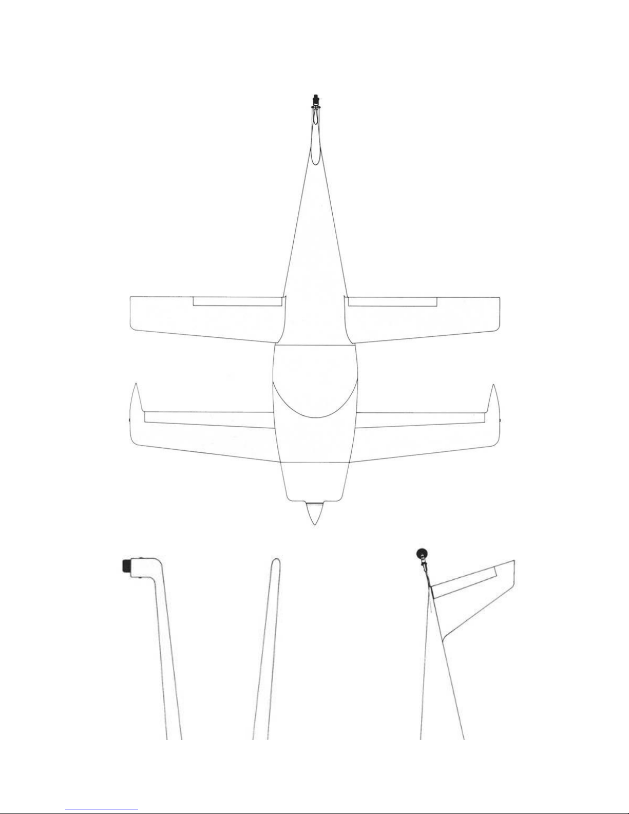
3-View drawing of the Q2
Aircraft serial number
Aircraft registration number, if available
(see step #2)
Approximate date of starting construction
Engine-type
FAA will then answer you, and tell you when they want to inspect
your airplane, where the approved test areas are, etc.
2. This step is optional, and applies only if you want to reserve a
specific registration number (the number you will paint on the
tail). You can ask for all numbers, numbers followed by a single
letter, or numbers followed by two letters. They are preceded by
the letter "N". (For example, N77Q, N8490P, etc.). Be sure to give
them your second and third choice, in case the number you want is
already taken. Send $10 to reserve your special number to:
Page 16

FAA Aircraft Registry
Box 25082
Oklahoma City, OK. 73125
Do not register your aircraft yet, since you don't need to pay
registration fees, property taxes, etc., until your airplane is
ready to fly. If you do not desire a special number, then the FAA
will assign you a random number.
3. When you are ready for inspection* contact your local FAA office.
Be sure you have an airframe log book (available from EAA) so that
FAA can make an inspection entry.
4. To prepare for your final inspection, be sure you have: The "N"
number painted on, the "Experimental" sign (2" high letters) on
the canopy frame, the ID plate, and an airframe log book and an
engine log book.
Before final inspection, fill out an application for registration
(FAA form #AC8050-1), a notarized affidavit that you built the
airplane from parts that you bought yourself, and include $5
registration fee, along with copies of your sales agreement and
invoice signed by Quickie Aircraft Corporation. Send those things
to:
FAA Registry
Box 25082
Oklahoma City, OK 73125
5. After you have made a final inspection of your aircraft, run the
engine, etc., but prior to any taxi tests or flights, contact your
local FAA office and tell them you are ready to fly. They will
have you fill out an application for airworthiness (form #8130-6),
inspect your airplane, and issue you an airworthiness certificate
and a list of operating limitations. When you have completed your
initial test period, contact FAA to get your operating limitations
amended so you can fly outside your test area.
• Refer to education section - inspection is done to major areas
(wing, canard, and fuselage) after the glass is applied, but
before the area is painted with any primer, etc., so that the
glass structure can be inspected. The FAA office has been supplied
with the same inspection criteria that you are given in your
Composite Materials Education Chapter.
PAGE
1-2
Page 17

Q2 Plans - Chapter 1 - Page 1-3
Page 18
Page 19

PAGE 1-3
Q2 Plans - Chapter 2 - Page 2-1
BILL OF MATERIALS
TOOLS
.....There are certain tools which are necessary to complete the
aircraft. Three lists of tools are provided here. The first is the
absolute bare minimum required, sacrificing efficiency; the second is a
recommended list for the best compromise of cost and work efficiency; the
third is a list for the "Cadillac" of shops where ease of construction is
more important than money. The non-common items are stocked by Aircraft
Spruce and Specialty.
FIRST LIST - BASIC REQUIRED TOOLS
• Common household butcher knife
• Coping saw
• 1/4" drive socket set
• Small open-end wrenches
• Sandpaper.
50 sheets, 40-grit, 3M Production Paper D-wt.
50 Sheets, 80-grit, 3M Production Paper D-wt. 20 sheets, 240-grit,
3M Wet or Dry Tri-M-Ite Paper
A-wt. Silicon Carbide Waterproof.
20 sheets, 320-grit, 3M Wet or Dry Tri-M-Ite Paper
A-wt. Silicon Carbide Waterproof.
• Small Weights - Approx. 150 lbs in 5-15 lb pieces
• 6 - 6" C-Clamps
• Square and half-round files
• Pliers
• 1" putty knife
• Hacksaw
• Blade & Phillips screwdrivers
• Box of single-edge razor blades
• 24" carpenter's level
• Carpenter's square
• Felt marking pens
• 3-ft straightedge
• 12-ft decimal steel tape (Stanley #61-112)
• 1/4" drill with set of fraction and number bits,
Page 20

#30, #32, #10, 1/4" and #12 bits
• Taps; 1/4-28, 10-32, 1/8 NPT (Pipe Tap)
• Roll of grey duct tape
• Saber saw
• Cheap hole saw set or flycutter
• Pop rivet puller
• Homemade balance for rationing epoxy
• Wall thermometer 50 to 100°F
• 6-ft straightedge
• Small set of X-Acto knives
• Dremel-type miniature high-speed hand grinder with saw and router
bits
SECOND LIST - RECOMMENDED TOOLS
(In addition to those in the first list)
• 6" to 9" disc-type hand sander
• Set of 1/4",1/2" and 1" chisels (wood)
• 1/2"-dia 100° counter sink (piloted)
• 6" machinist steel ruler
• X-Acto razor saw
• 3/8" variable-speed hand drill
• Hand broom/brush
• Bench-mounted belt sander
• Stanley surform plane
• Vacuum cleaner (shop type)
• Dovetail saw
• Epoxy Ratio Pump
• Plumb bob
THIRD LIST - FOR THE FIRST CLASS SHOP
(In addition to those in the first and second list)
• Drill press
• 18-inch band saw
• Vernier Caliper
• 90° drill adapter
• Air compressor with blow nozzle
• Orbital sander
• NICO press sleeve tool
• Clecos - one dozen 1/8"
• Hotwire Voltage Control
ITEMS USED ONLY OCCASIONALLY AND CAN BE BORROWED
• 1 dozen 1/8" Clecos
• Hotwire Voltage Control
Page 21

• 5/8" Spotface
PACKING LISTS
.....Upon receiving your Q2 kit, you should immediately match the packing
list in each shipment against the actual contents of each box. Any
discrepancies should be reported immediately to Quickie Aircraft
Corporation. We will not be responsible for shortages that go unreported
for longer than 30 days after receipt of the materials.
.....Quickie Aircraft Corporation maintains a close liaison with Q2
subcontractors to assure proper materials specification and quality
control. Do not make substitutions for the materials provided. The
materials provided were selected, developed, tested, and optimized for
ease of construction and structural integrity. If you insist on making
non-approved substitutions for replacement and spoilage, we insist that
you do not call your aircraft a Q2. Quickie Aircraft Corporation will not
provide assistance in the application of substitute materials or
components.
.....In addition to the materials provided in the kit, you will need to
furnish a few items that are readily available locally. We do this to
save you some money. These items are as follows:
• Lumber for a workbench and jigging
• Masonite, hardboard, plywood, etc. for jigging
• templates, rigging templates, and hot-wire templates
• 12" piece of 1/4" diameter wood dowel
• 6" x 6" piece of aluminum screen door screen .Battery for
electrical system
• Finishing materials: Dupont 70S dark gray laquer primer surfacer,
Acrylic laquer paint "in the color of your choice
• 1 piece shock cord, 3- 4" unstretched length
END OF CHAPTER
PAGE 2-1
Page 22

Q2 Plans - Chapter 3 - Page 3-01
COMPOSITE MATERIALS EDUCATION
.....DON'T SKIP THIS SECTION. Every hour you spend in this preparation
section will save you five when you really start building your
aircraft.
INTRODUCTION
..... In this section you won't build any part of your airplane. What
you will do is learn how to build your airplane the right way. The
construction techniques may be radically different from anything
you've done before (including building boats, surfboards, airplanes,
and go carts), and you should assume there is only one correct way to
do it. We've discovered many wrong ways of doing things and have
written the plans to keep you from repeating our mistakes. We insist
that you do things our way. If you have a better idea, suggest it to
us; we'll test, and if it really is a better idea we'll publish
details in the Quickie Newsletter.
.....This section will teach you all of the techniques required to
build your airplane, show you what special tools you need, and how to
use them. The educational samples that you will build in this section
are designed to give you experience and confidence in all of the
techniques that you will use in the construction of your airplane. The
steps in construction of each sample are arranged in sequence (as are
the steps in construction of the actual aircraft parts) and you should
follow the sequence without skipping any steps. You will learn the
basic glass lay up technique used throughout the aircraft, special
corner treatments, foam shaping/cutting, and joining methods. A
summary of these techniques is provided on yellow paper for you to
tack up on your shop wall.
THE FOLLOWING TOOLS ARE ONES YOU MAKE:
Sanding Blocks
..... These are required in many areas during construction and for
finishing. You may also use a "soft block", which is a block of the
blue-white or orange Styrofoam wrapped with sandpaper.
Page 23
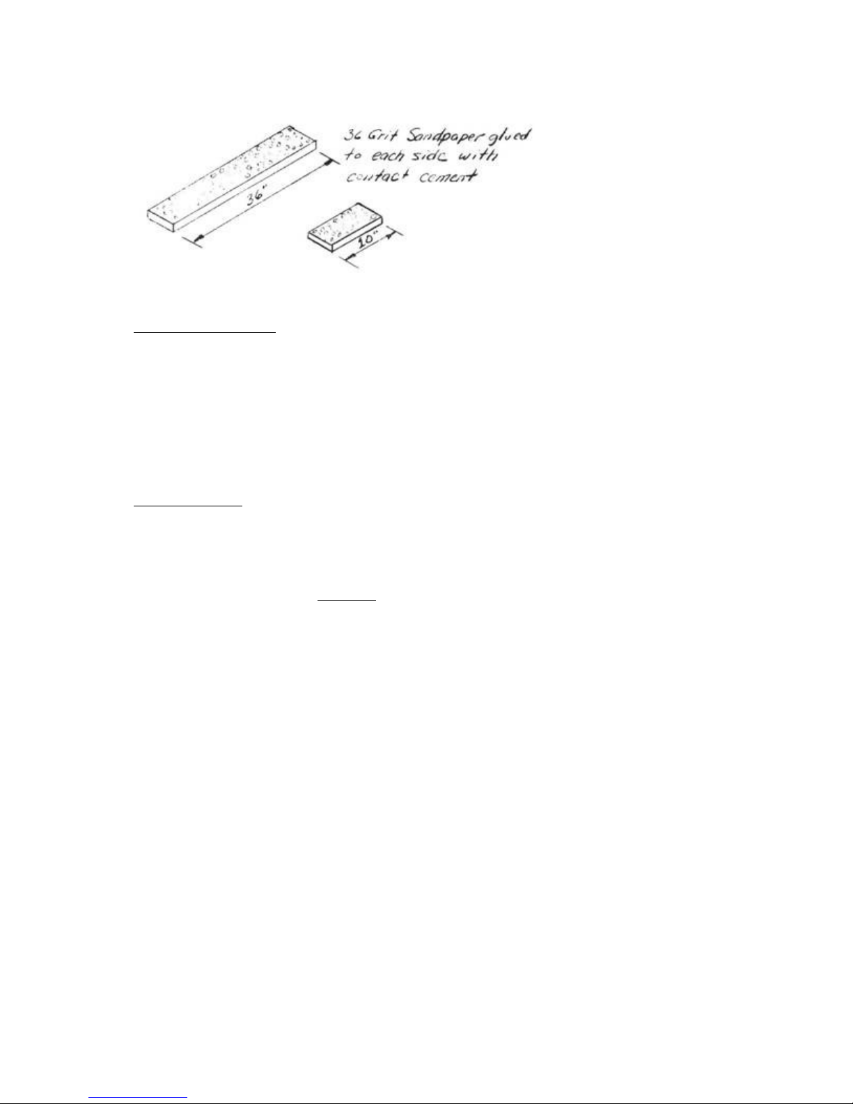
Much elbow grease is saved if you replace the
sandpaper often.
Long Straightedge
..... This is not absolutely required, but is quite handy when jigging
or checking the straightness of flying surfaces. It is merely a 6-ft
or 8-ft lx3 or lx4 piece of lumber that is hand-selected to be
"eyeball straight". You can get it one of two ways: (1) Order it from
Aircraft Spruce & Specialty Co., or Wicks Aircraft Supply - they plane
them perfect from dry lumber. (2) Sort through the lumber (dry fir or
redwood) at your local lumber yard until you find one that looks
straight when you eyeball it from one end. Mark it and hang it on the
wall so it doesn't end up as part of a shelf!
Epoxy Balance
..... Devices which automatically ratio the correct amount of resin
and hardener and dispense it with the pull of a lever are available
from Aircraft Spruce & Specialty Co., and Wicks Aircraft Supply, for
approximately $150. These save time and epoxy. You can ratio the epoxy
by building the following simple balance - don't skip steps!
.....Follow each step exactly every time you mix epoxy.
Place both empty cups as shown (wet
1.
the hardener cup).
Adjust ballast weight to level mark.
2.
Fill resin cup with desired amount of
3.
resin 1 to 6 oz.
Add hardener to hardener cup to
4.
balance scale on level mark.
Pour the hardener into the resin cup
5.
and mix.
Page 24
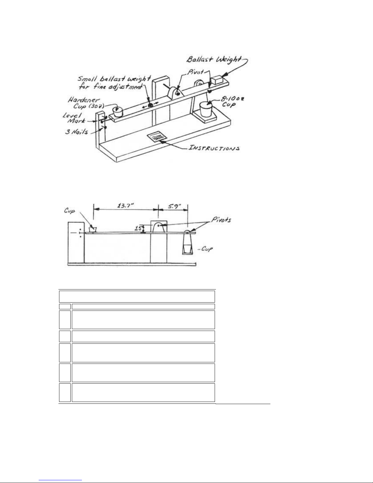
Pivots - metal tube bushings in wood. Loose fit on
nails. The 1/8" dia. brass tube available at hobby
shops is excellent for the bushings. MUST BE
FRICTION FREE.
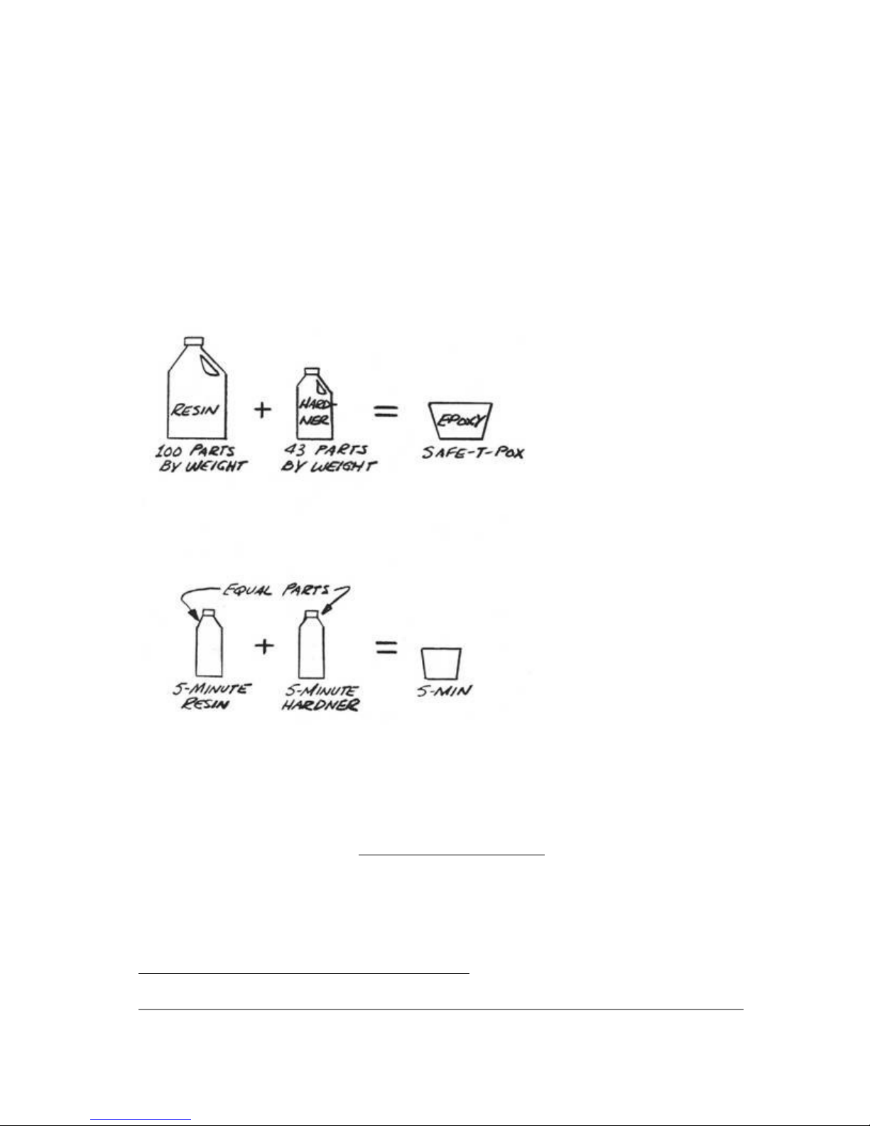
These ratios result in a 43-part hardener to
100-part resin mix.
RATIO BALANCE FOR RESIN/HARDENER
1. Place both empty cups as shown (wet
the hardener cup).
2. Adjust ballast weight to level mark.
3. Fill resin cup with desired amount of
resin 1 to 6 oz.
4. Add hardener to hardener cup to
balance scale on level mark.
5. Pour the hardener into the resin cup
and mix.
..... You will need a hot wire cutter to carve all the foam cores for
the canard, vertical fin, and wing. Refer to sketch.
Hot Wire Cutter
Page 25
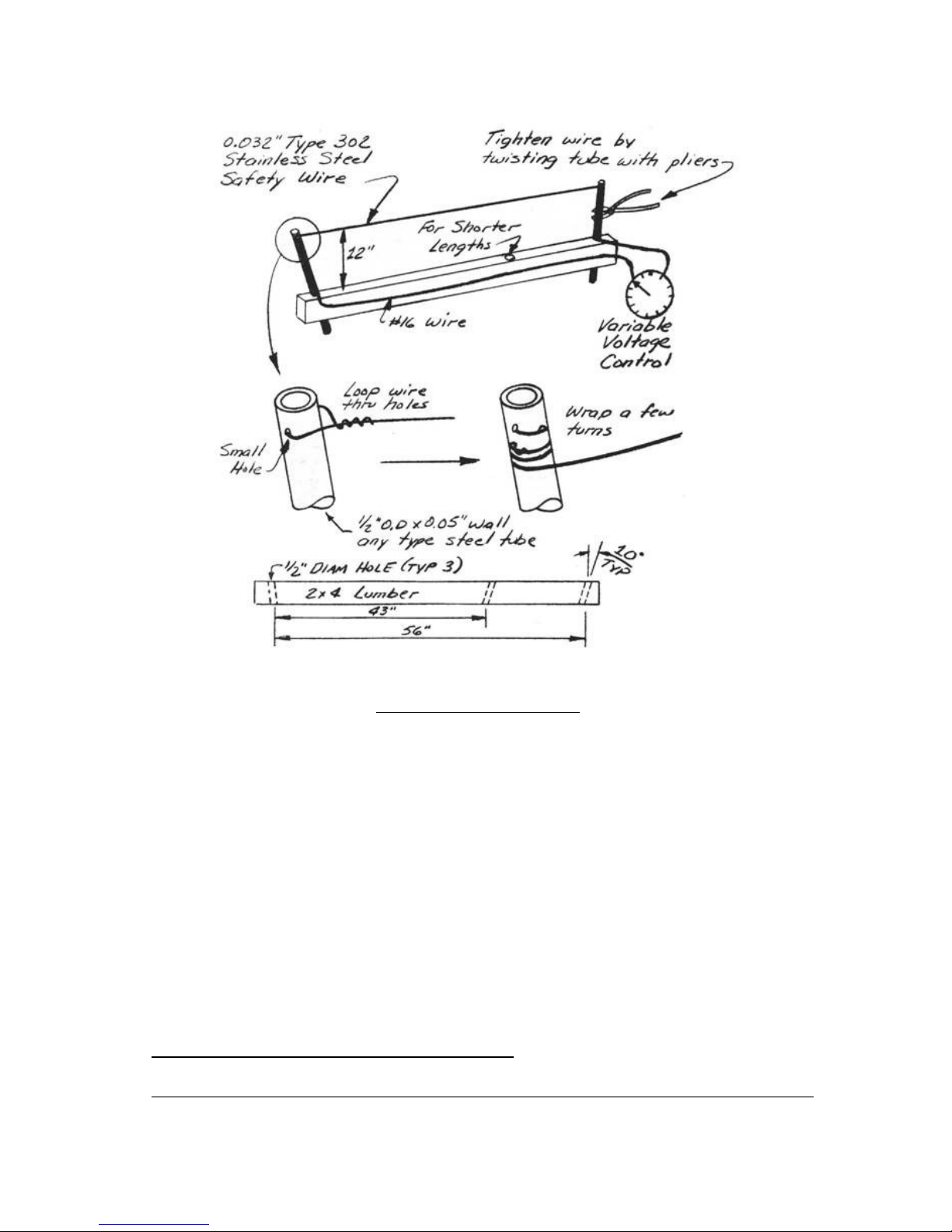
CONTINUED ON NEXT PAGE
PAGE 3-1
Q2 Plans - Chapter 3 - Page 3-02
Page 26
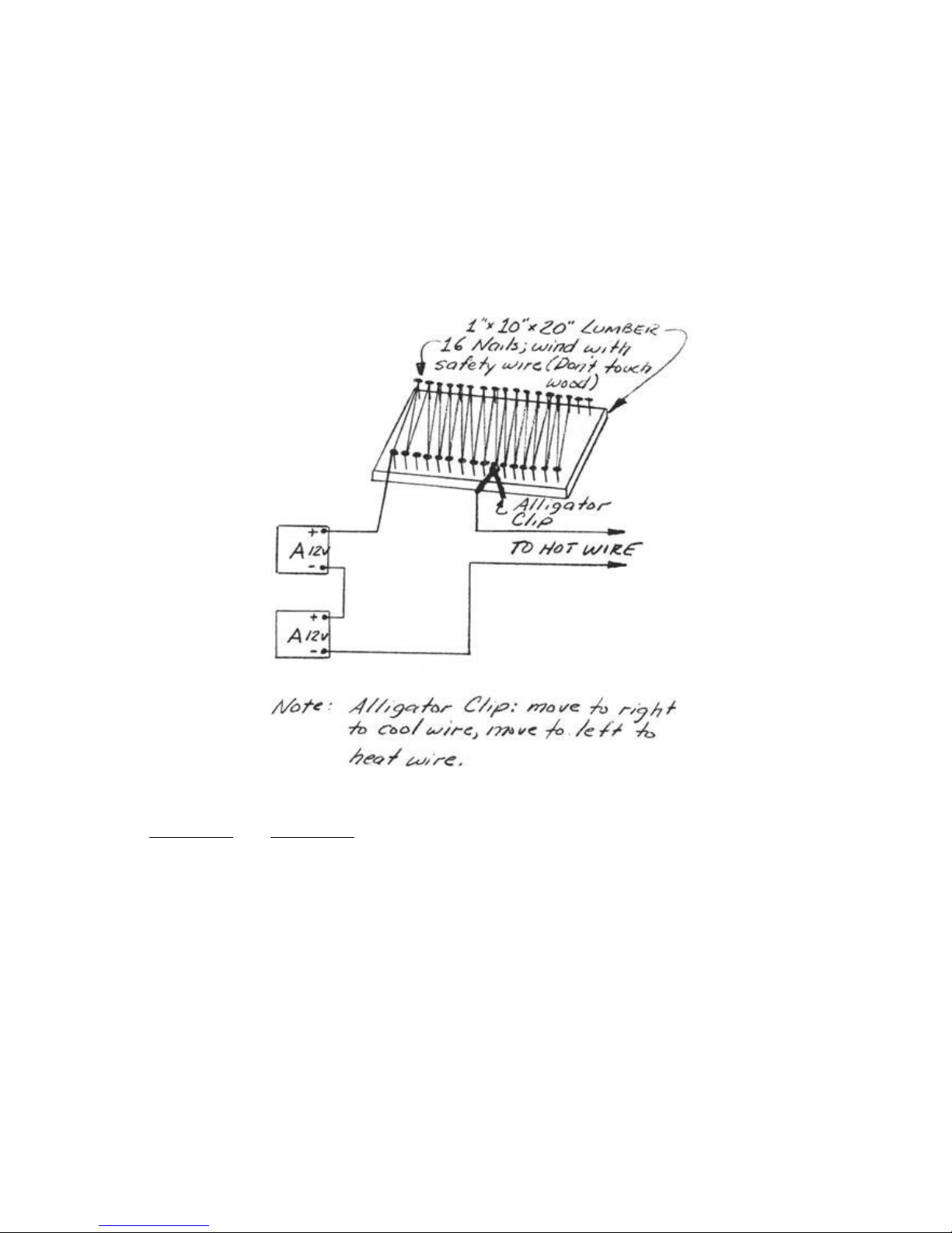
..... The variable voltage control can be obtained from Aircraft
Spruce and Specialty or Wicks Aircraft Supply, or you can substitute
any controllable power supply to include the 14 to 20 volt range with
at least 4 amp capability. An alternative is to borrow two 12-V
battery chargers or auto batteries and lash up the following device.
The "A" blocks represent either a battery or a 12-V dc battery charger
with a 4 amp capability.
..... The cutter should only be used on the blue-white or orange
styrofoam. A hazardous gas is emitted if you try to cut urethane.
.....You can substitute .025 nicrome wire which can be run at a lower
current (about 2 amp) but nicrome wire is difficult to find. Adjust
the current to obtain a wire temperature which will allow the wire to
cut the foam at a rate of one inch every four to six seconds when
pulled with a light load (less than ! pound). This can be checked with
a small scrap of foam. If temperature is correct, the foam will have
smooth hairy surface. A cratered surface means too much heat. If the
wire is too cold, the cutter will have to be forced hard, causing the
wire to lag. Lag should not exceed 1 inch over the top and bottom of
the wing and not over 1/8 inch around the leading edge. If the wire is
too hot, it will burn away too much foam, making the part too small
and will result in ruts in the foam if the wire is inadvertently
stopped during cutting. The wire should be tightened until the wire
starts to yield. Check this by tightening the wire while plunking it,
listening to the sound. The pitch will increase until the wire yields.
Page 27
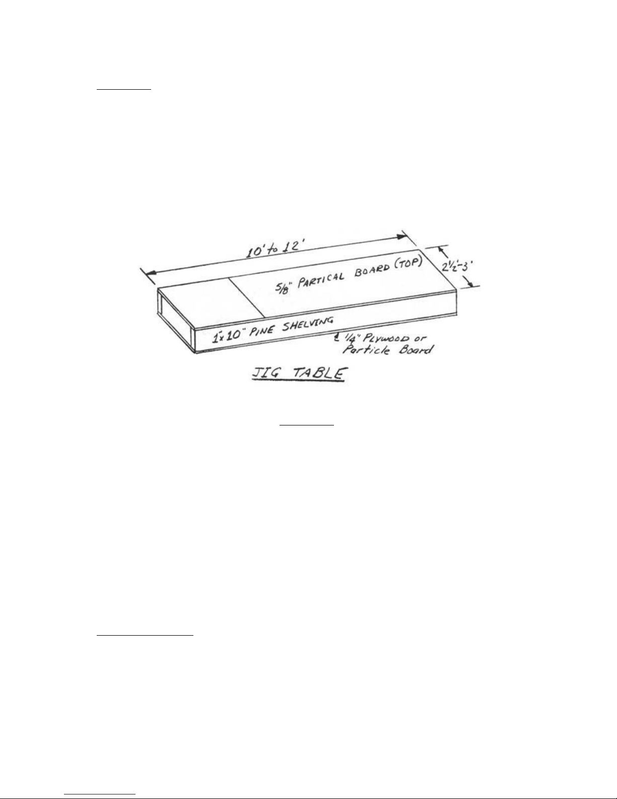
Jig Table
..... You will need a table to jig and build the wings and canard. It
should be at least 2 ft by 10 ft. Any larger than 4 ft. by 12 ft. will
just get in the way. Use a little care in making a flat, untwisted
surface. The following is a sketch of the one we made and it works
fine. The box design makes it stiff in torsion. Set it up with the top
35 to 39 inches above the floor. Don't get carried away with surface
finish, since you are going to be gluing blocks to it with Bondo and
chiseling them off several times.
.....When building the wing and canard, which are nearly 17 ft long,
one can extend the jig table with lumber (2x4's) and Bondo (see
section on Bondo) to provide a platform for the top jigging templates.
MATERIALS
..... The materials, processes, and terminology used in the
construction of your Q2 are recent to homebuilding. This section is
devoted to familiarizing you with the language, materials, and
techniques used in these plans. This information is basic to the
construction of your airplane. You should study this section and be
sure that you understand all of it before continuing.
.....There are five basic materials that you will be working with:
fiberg1ass cloth, epoxy, microspheres, flox, and foam. Each material,
its properties, and uses, will be discussed in detail. Basic processes
using these materials will also be discussed.
Fiberglass Cloth
..... The most basic structural material in your Q2 is glass cloth.
Glass cloth is available commercially in hundreds of different
weights, weaves, strengths, and working properties. The use of glass
in aircraft structures, particularly structural sandwich composites,
is a recent development. Very few of the commercially available glass
cloth types are compatible with aircraft requirements for high
Page 28

strength and light weight. Even fewer are suitable for the hand layup
techniques used in the Q2. The glass cloth used in the Q2 has been
specifically selected for the optimum combination of workability,
strength, and weight.
.....The glass cloth in your Q2 carries primary loads, and its correct
application is of vital importance. Even though doing your glass work
correctly is important, this doesn't mean that it is difficult.
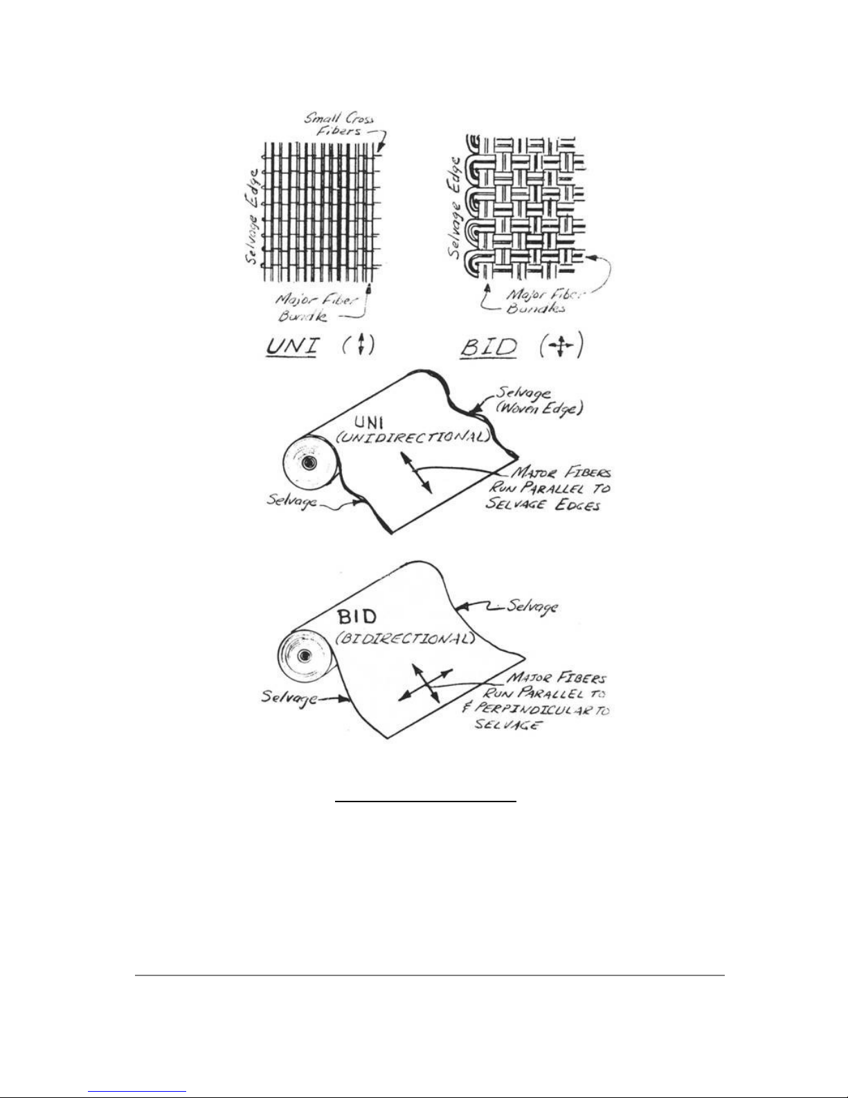
.....Two types of glass cloth are used, a bi-directional cloth
(5277BID), and a unidirectional cloth (5177UND). (Use the full part
number for ordering your cloth, but for simplicity the plans will use
only BID or UNI designations). BID cloth has half of the fibers woven
parallel to the selvage edge of the cloth and the other half at right
angles to the selvage, giving the cloth the same strength in both
directions. The selvage is the woven edge of a bolt of fabric as shown
in the accompanying sketch.
Page 29
CONTINUED ON NEXT PAGE
Page 30
Q2 Plans - Chapter 3 - Page 3-03
..... UNI cloth has 95% of the glass volume woven parallel to the selvage
giving exceptional strength in that direction and very little at right
angles to it.
.....BID is generally used as pieces which are cut at a 45-degree angle
to the selvage and laid into contours with very little effort. BID is
often applied at 45 degree orientation to obtain a desired torsional or
shear stiffness. UNI is used in areas where the primary loads are in one
direction, and maximum efficiency is required, such as the wing skins and
spar caps.
.....Multiple layers of glass cloth are laminated together to form the
aircraft .structure. Each layer of cloth is called a ply and this term
will be used throughout the plans.
.....Marking and cutting the plies of glass cloth is a job that you will
repeat often in the construction of your Q2. Glass cloth should be
marked, cut, and stored in a clean area with clean hands and clean tools.
Glass contaminated with dirt, grease, or epoxy should be discarded. A
clean, smooth surface is needed for marking and cutting. The area used
for storing and cutting glass cloth should be separated from the aircraft
assembly area because otherwise it will be exposed to foam dust, epoxy,
and other things which can contaminate the cloth. You will need a good
sharp pair of scissors, a felt-tipped marker, a fairly straight board,
and a tape measure for marking and cutting. The small amount of ink from
marking and numbering plies has no detrimental effects on the glass
cloth.
.....In each step the size, type, and fiber orientation of each ply is
given. Take the list to your glass cutting table, rollout a length of the
appropriate cloth, straighten the selvage, mark all of the plies, and cut
them.
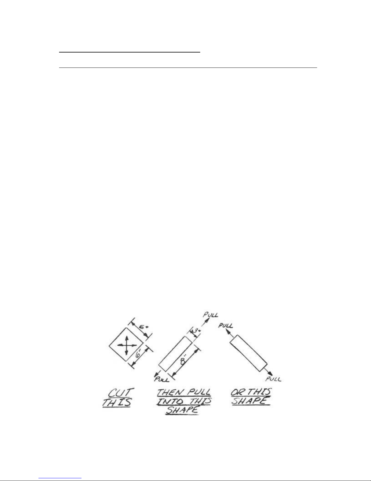
.....Now is a good time to stop reading long enough to go and cut a
square ply of BID and see how easy it is to change its shape by pulling
and pushing on the edges as shown in the sketches. Cut a square with the
fibers running at 45° and pull on the edges to shape the piece.
..... It helps if you make fairly straight cuts, but don't worry if your
cut is within 1 inch of your mark. As you cut BID, it may change shape,
Page 31

just as the square ply that you are experimenting with does when you pull
on one edge. Plies that distort when cut are easily put back into shape
by pulling on an edge. Rolling or folding cut plies will help keep them
clean and make it easier to maintain their shape. If several plies are
called for, it may help to number them before cutting. Save your clean
scraps and make an effort to use them for smaller plies, If the cloth is
spotted with epoxy, throw it away.
.....When cutting long strips or large pieces of 45degree BID, always
roll or fold it so it keeps its shape when handled. When it's applied, it
can be set on one end of the part and rolled onto it. If you pick up each
end, it will distort and not fit the part properly.
.....The fiber orientation called for in each lamination is important and
shouldn't be ignored. UNI is characterized by the major fiber bundles
running parallel to the selvage and being much larger than the small
cross fibers which run at right angles to the selvage. In BID the cross
fibers are the same size as those running parallel to the selvage, giving
BID an even "checkerboard" appearance. BID is commonly used for plies cut
at 45° to the selvage. Your tailor would call this a "bias" cut. The 45°
cut makes it easy to work wrinkles out of a ply locally, without having
to chase it to the far edge. The 45° cut also makes it possible to make a
ply slightly longer than originally cut by pulling on the ends, or wider
by pulling the sides. The 45° orientation isn't critical; you don't need
to measure it. Your eyeball of a rough diagonal (45° ±10°) is adequate
when either cutting or laying up the cloth.
EPOXY
..... In recent years the term "epoxy" has become a household word.
Unfortunately, "epoxy" is the general term for a vast number of
specialized resin/hardener systems, the same as "aluminum" is a general
term for a whole family of specialized metal alloys. Just as the
"aluminum" pots and pans in your kitchen, the "epoxy" in your Q2 is
vastly different from the hardware store variety.
.....Epoxy is the adhesive matrix that keeps the plies of load-carrying
glass cloth together. Epoxy alone is weak and heavy. It is important to
use it properly so that the full benefits of its adhesive capability are
obtained without unnecessary weight. A large portion of your education in
composite structural work will be spent learning how to get the full
strength of an epoxy/glass mixture with the minimum weight. This section
will discuss the terminology and techniques for working with epoxy resin
and its hardener.
.....An "epoxy system" is made up of a resin and a hardener tailored to
produce a variety of physical and working properties. The mixing of resin
with its hardener causes a chemical reaction called curing_ which changes
the two liquids into a solid. Different epoxy systems produce a wide
variety of solids ranging from extremely hard to very flexible. Epoxy
systems also vary greatly in their working properties, some are very
thick, slow pouring liquids and others are like water. Some epoxy systems
allow hours of working time and others harden almost as fast as they are
mixed. A single type of resin is sometimes used with a variety of
hardeners to obtain a number of different characteristics. In short,
there is no universal epoxy system; each has its own specific purpose and
while it may be the best for one application, it could be the worst
possible in another use.
.....The epoxy systems used in the construction of your Q2 are tailored
for a combination of workability and strength_ as well as to protect the
Page 32
foam core from heat damage and solvent attack. These systems are very low
in toxicity to minimize epoxy rash. The epoxies are not similar to the
common types normally marketed for fiberglass laminating. Two different
systems are used in the Q2: a normal curing system, and a 5-minute
system.
The very fast curing (5-min.) system is used much like clecos are used in
sheet metal construction (or clamps in woodwork); for temporary
positioning. Five minute is also used in some areas where high strength
is not required, but here a fast cure will aid assembly.
.....Safe-T-Pox will cure to a firm structure at room temperature within
one day. Complete cure takes 14 days.
The Q2 epoxy systems are called Safe-T-Pox and
5-MIN.
..... Any foam bonding where parts are small and the fast cure allows the
next step to be done soon. Also used as a temporary joint for jigging.
Q2 Plans - Chapter 3 - Page 3-04
CONTINUED ON NEXT PAGE
PAGE 3-3
Page 33

..... The working and strength characteristics of an epoxy system are
dependent on the resin, the hardener, and on the amount of each in a
given mixture. Epoxy systems are engineered for a specific ratio of
resin and hardener. It is quite important that the proper mixture be
obtained. An accurate balance or ratio pump must be used to accomplish
this. A drawing of an inexpensive ratio balance is included in these
plans. The mix ratio accuracy is particularly important with Safe-TPox. The 5-Min. can be adequately rationed by merely pouring a blob of
part A in a cup and adding a blob of part B that looks the same volume
before mixing. Never eyeball estimate Safe-T-Pox, always carefully use
the balance or pump.
.....Epoxy resin and hardener are mixed in small batches, usually 6
ounces or less, even in the largest layup. The reason for small
batches is that, in large batches, as the hardening reaction
progresses, heat is generated which speeds the reaction, which causes
even more heat, which ends up in a fast reaction called an exotherm.
An exotherm will cause the cup of epoxy to get hot and begin to
thicken rapidly. If this occurs, throw it away and mix a new batch.
The small volume batch avoids the exotherm. For a large layup, you
will mix many small batches rather than a few large ones. With this
method you can spend many hours on a large layup using epoxy that has
a working life of only a few minutes. If the epoxy is spread thin as
in a layup its curing heat will quickly dissipate and it will remain
only a few degrees above room temperature. However, in a thick buildup
or cup, the low surface area to mass ratio will cause the epoxy to
retain its heat, increasing its temperature. This results in a faster
cure causing more heat. This unstable reaction is called an exotherm.
Exotherm temperatures can easily exceed the maximum allowable for foam
(200°F) and damage the foam-to-qlass bond.
.....Unwaxed paper cups are used for mixing and ratioing resin and
hardener. Convenient 8-oz cups for resin are provided. The hardener
cups are the 3-oz unwaxed bathroom paper cups. Don't use waxed cups;
the wax will contaminate your epoxy.
.....If you are using the homebuilt balance, follow this procedure.
Place the resin (8 oz) cup on the right cradle. The resin cup can be
either a new clean cup, one with a little uncured epoxy left in the
bottom, or a clean cup from a previous layup with hard epoxy in the
bottom (smooth, not lumpy). Now, take a clean 3-oz hardener cup - pour
a splash of hardener into it then scrape the hardener back into the
container. This gives the hardener a wet surface, so its remaining
hardener will not be counted in the balancing. Now, place the wet
hardener cup on the scale, check that it swings freely and balance it
perfectly by moving the small weight. Epoxy is then poured into the 8
oz cup (6 oz or less). Hardener is then poured into the 3 oz cup at
the other end of the balance until the arm is level. When ready to
mix, pour the hardener into the resin cup and mix completely. If you
have the ratio pump, you simply put one cup under the spout, pump out
the amount that you want and mix.
.....
Mixing is done by stirring with a stick, being careful not to spill
any. If you spill part of an unmixed cup, the ratio of resin and
hardener may be inaccurate and it shouldn't be used. Mix each cup for
at least two minutes. You should spend 80% of your mixing time
stirring the cup and 20% scraping the sides to assure complete mixing.
Page 34

Do not mix with a brush. The bristles can soak up the hardener,
changing the ratio. Use a tongue depressor or wood stick.
.....The working temperature has a substantial effect on the pot life
and cure time. Very hot conditions will cause the cure to speed up. In
cold working conditions the cure will be delayed and if it is cold
enough, epoxy may not cure at all. Working temperatures must be
between 70° and 9O°F. A range of 75 to 80°F is best. Be sure to get a
wall thermometer (approx. $1.50 at any general store) to check the
temperature of your work area. At 75°F, 5-Min must be used within four
minutes, and Safe-T-Pox must be used within 20 minutes.
.....Cold epoxy results in increased time required to do a layup,
since it takes longer to "wet" and to squeegee the cloth. A layup at
65° may take almost twice the time as at 75°F. On most layups (except
for joining foam cores) its best to have 75 to 80°F room temperature
and 80 to 9O°F epoxy. Resin and hardener can be kept warmer than room
temperature by keeping it in a cabinet with a small light bulb on. DO
NOT store your resin or hardener on a cold floor if you plan to use it
within the next several hours. If YOU let your shop get cold between
working periods, keep some resin and hardener in the warmest place of
your house for use on the next layup.
.....Save your mixing cups, as they can be used as a quality check of
your epoxy. After a day or two take a sharp knife point or scribe and
scratch the surface of epoxy in the cured cup. If the epoxy cured
properly, the scribe will make a white scratch mark. If the epoxy
hasn't cured, the scribe will make a dull ridge, indicating a soft
surface. If this occurs, the epoxy has not cured, either due to
inadequate time or temperature, or bad mixing, or bad epoxy.
MICROSPHERES
..... Microspheres are a very light filler or thickening material used
in a mixture with epoxy. Micro, as the mixture is called, is used to
fill voids and low areas, to glue foam blocks together, and as a bond
between foams and glass skins. The glass bubble-type supplied is
lighter than most common types. Microballoons must be kept dry. If
moisture is present it will make them lumpy. Bake them at 250°F; then
sift with a flour sifter to remove lumps.
.....Micro is used in three consistencies; a "slurry" which is a one-
to-one by volume mix of epoxy and microspheres, "wet micro" which is
about two-to-four parts microspheres by volume to one part epoxy, and
"dry micro" which is a mix of epoxy and enough microspheres to obtain
a paste which will not sag or run (about five parts-to-one by volume).
In all three, microspheres are added to completely mixed epoxy.
.....You do not have to accurately mix the microspheres; just dump
them in until the desired consistency is obtained. Micro slurry is
used to paint over foams before glass cloth is applied over them.
Slurry is almost the same viscosity as the pure epoxy and is runny
enough to apply with a brush. However, the easiest way to apply slurry
is to pour it onto the surface and spread it out evenly using a
squeegee. When skinning urethane foam use a full thick coat of slurry.
Inadequate slurry on urethane can result in a poor. skin bond. Wet
micro is used to join foam blocks, and, while it is much thicker than
slurry, it is still thin enough to sag and run (like thick honey). Dry
micro is used to fill low spots and voids and is mixed so that it is a
dry paste that won't sag at all. In all three micro types, you don't
measure, just add microspheres until the desired consistency is
Page 35
obtained. Use micro only as specifically shown - never use micro
between glass layers.
....
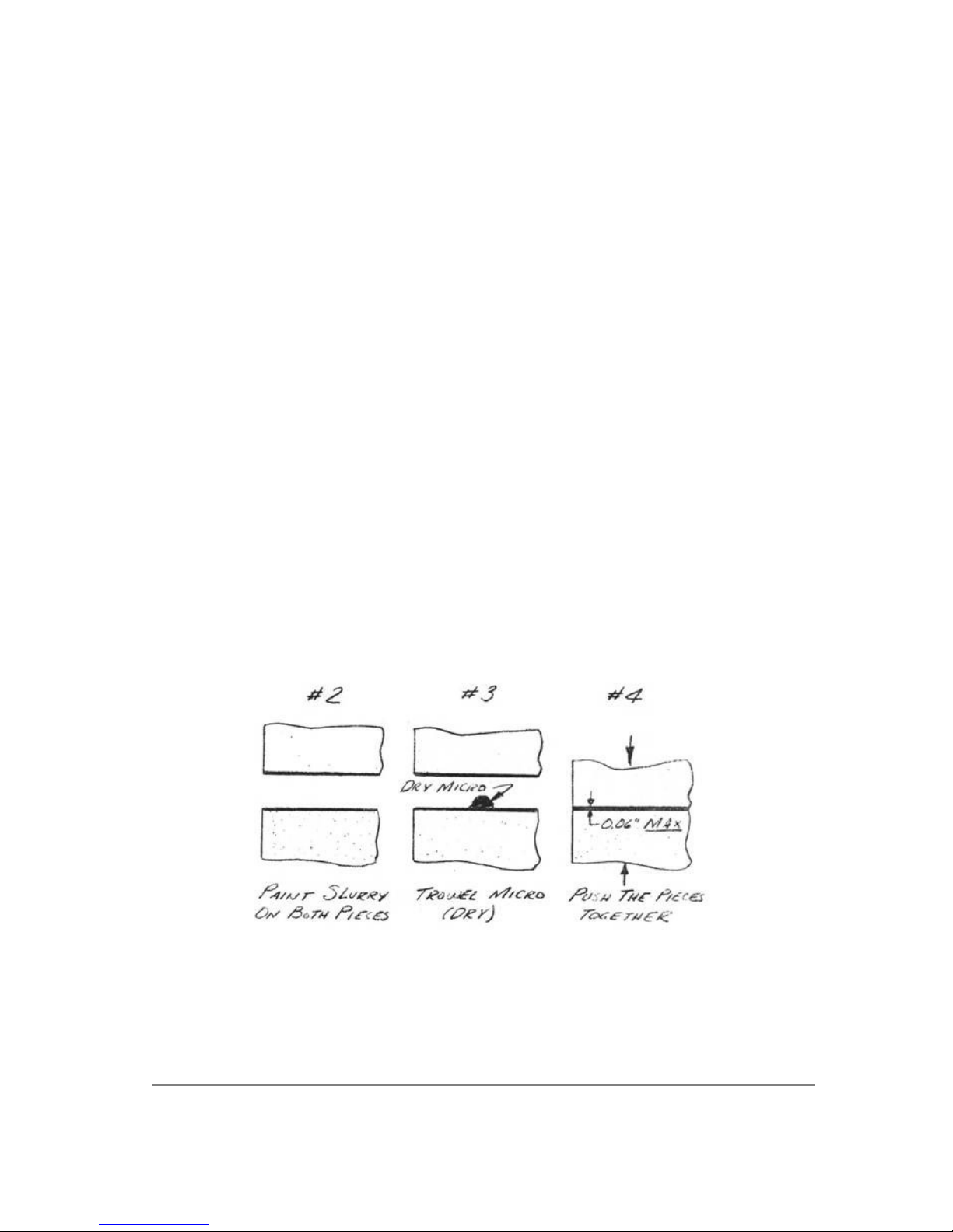
Always use the following method to join foam blocks. This is extremely
important.
1. Check that the foam blocks fit closely together.
If there are voids over 1/16 inch, sand to fit, or
fill the void with a sliver of foam.
2. Paint a light coat of micro slurry on both
surfaces. If joining foam to fiberglass, paint
pure mixed epoxy (no microspheres) on the
fiberglass surface and micro slurry on the foam
surface.
3. Refer to the sketch and trowel wet or dry micro in
the center of the joint. Thus when joined the
micro is pushed outward expelling (rather than
trapping) air. If the fit is excellent use dry
micro.
4. Push the two pieces together, wiggling each to
move the micro toward the surfaces. Be sure the
micro is no thicker than 0.1 inch at any place, to
avoid exotherm. Wipe off any excess. Do not be
concerned if the micro does not completely reach
the surface. That void can be filled immediately
before skinning the part.
PAGE 3-4
Page 36

Q2 Plans - Chapter 3 - Page 3-05
FLOX
..... Flox is a mixture of cotton fiber (flocked cotton) and epoxy. The
mixture is used in structural joints and in areas where a very hard,
durable buildup is required. Flox is mixed much the same as dry micro,
but only about two parts flock to one part epoxy is required. Mix in just
enough flox to make the mixture stand up. If "wet flox" is called out,
mix it so it will sag or run.
..... When using flox to bond a metal part be sure to sand the metal dull
with 220-grit sandpaper and paint pure mixed epoxy (no f10x) on the metal
part.
BONDO
..... Throughout these plans the term "Bondo" is used as a general term
for automotive, polyester body filler. Bondo is used for holding jig
blocks in place and other temporary fastening jobs. We use it because it
hardens in a very short time and can be chipped or sanded off without
damaging the fiberglass. Bondo is usually a dull gray color until a
colored hardener is mixed with it. The color of the mixture is used to
judge how fast it will set. The more hardener you add, the brighter the
color of the mixture gets, and the faster it hardens. This simple guide
Page 37

works up to a point where so much hardener is added that the mixture
never hardens. Follow the general directions on the Bondo can for fast
setting Bondo. Mixing is done on a scrap piece of cardboard or plywood
(or almost anything), using a hard squeegee or putty knife. A blob of
Bondo is scooped out of the can and dropped on the mixing board. A small
amount of hardener is squeezed out onto the blob and then you mix to an
even color. You will mix the blob for about one minute. You will then
have two to three minutes to apply it before it hardens.
..... Be sure to clean the board and putty knife off before the Bondo is
completely hard. MEK will clean Bondo off your putty knife and squeegee
if it isn't completely hardened.
PEEL PLY
..... Peel ply is a layer of 2.70z dacron fabric which is laid up over a
fiberglass layup while the fiberglass is still wet, and is later removed
by lifting an edge and "peeling" it off. The most convenient form of
dacron to use is "surface tapes", normally used in covering fabric
aircraft. These are available in rolls. You wi11 need at least one roll,
2" wide. Peel ply is used for two purposes:
(1) Peel ply any area that will later be structurally attached to
another fiberglass layup. Once the dacron is peeled off, the
surface is ready for another layup, without sanding. If you do
not use peel ply, you will have to sand the surface completely
dull (no shiny spots). This sanding is hard, itchy work and
ruins the strength of the outer ply of fiberglass.
.....Note that to peel ply the trailing edge overlap area, the peel ply
is the First ply made to the foam core, Lay a strip of dacron down on the
overlap notch and secure it with tacks or staples so it doesn't move when
you layup the skin.
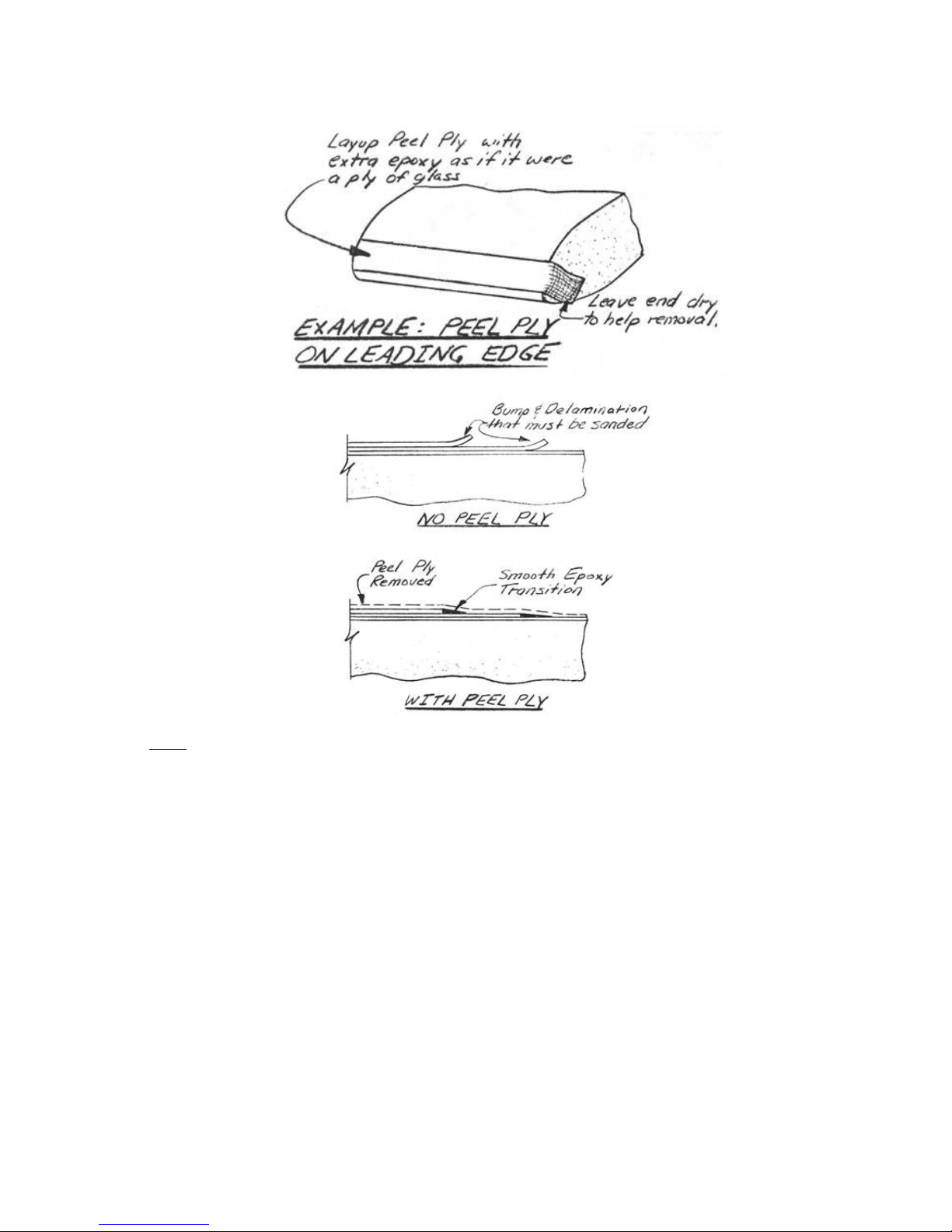
(2) The second use for peel ply is to transition the area where
the top ply of a layup terminates on the fiberglass surface.
.....Refer to the adjacent sketches. If the top ply edge is laid up bare
it results in a rough edge that can delaminate if a little dry. Sanding
the rough edge is hard, itchy work and usually results in damaging the
adjacent surface. If the edge is overlaid with a strip of dacron during
the layup (lay on the dacron and wet out by stippling or squeegeeing) it
will make the edge lay down flat and will form a wedge of epoxy to
smoothly transition the edge. After cure, peel off the dacron. The result
is a beautifully transitioned smooth edge with no delamination tendency.
Use this method in all places where a cloth edge terminates on the
surface.
Page 38
FOAM
..... Three different types of rigid, closedcel1 foam are used. A low
density (nominally 2 lb/ft3) b1ue¬white or orange, large-cell styrofoam
is used as the foam core of the wing, canard, vertical stabilizer, and
control surfaces. The blue-white or orange foam is exceptional for smooth
hot wire cutting of airfoil shapes. The large cell type used provides
better protection from delamination than the more commonly used
insulation-grade styrofoams.
.....Low density 2 lb/ft3 green or light tan urethane foam is used
because it is easy to carve and contour, and is completely fuel proof.
The urethane used is Urethane 210 or equivalent.
.....The white styrene modified urethane foam is used in medium density
(4-6 lb/ft3) where higher compression strength is required.
.....Do not substitute foams for those supplied by Quickie Aircraft
Corporation. For example, the Q2 blue-white or orange styrofoam has great
glass surface peel strength than the standard blue styrofoam sold by some
distributors. Also, we considered using the "fire resistant" BROWN
urethane instead of the green 2 lb urethane, but found its physical
properties, fatigue life, and fuel compatibility to be much lower than
the urethane supplied to Q2 builders. Do not confuse styrofoam with white
expanded polystyrene. Expanded polystyrene is a molded, white, low
Page 39

density, soft foam, which has the appearance of many spheres pressed
together. This is the type used in the average picnic cooler. It
disappears immediat1ey in the presence of most solvents, including fuel,
and its compression and modulus is too low.
.....All three types of foams, urethane, styrene modified urethane, and
polystyrenes are manufactured in a wide variety of f1exibilities,
densities and cell sizes. Getting the wrong material for your airplane
can result in more work and/or degraded structural integrity. Since
sunlight can damage foam, avoid exposure of foam to the sunlight by
keeping it covered.
END OF SECTION
Q2 Plans – Chapter 3- Page 3-06
CONSTRUCTION TECHNIQUES
HOT WIRE CUTTING
..... The airfoil-shaped surfaces of your Q2 are formed by hot wire
cutting the orange or blue-white styrofoam of 2 lb/ft3 density. The
hot wire process given airfoils that are true to contour, tapered,
properly twisted, and swept with a minimum of effort and the simplest
of tools. The details for making your hot wire saw were shown
earlier.
.....The hot wire saw is a piece of stainless steel safety wire,
stretched tight between two pieces of tubing. The wire gets hot when
an electrical current passes through it and this thin, hot wire burns
through the foam. By making smooth steady passes, the hot wire gives
a smooth, even surface. The foam offers little resistance to the hot
wire's passage. To get a smooth accurate cut, a template is required.
Page 40
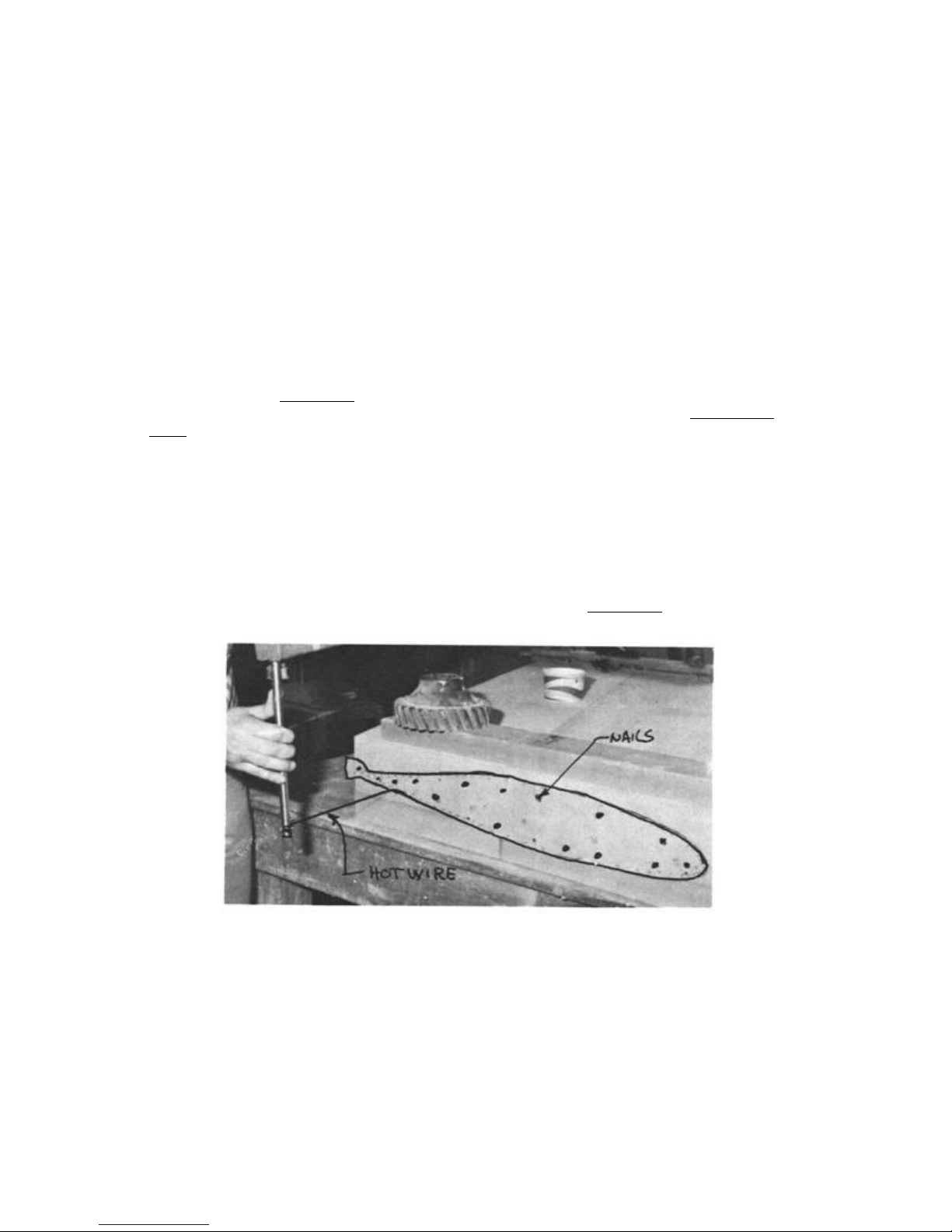
Templates are made from thin plywood, sheet metal, masonite or
Formica. A variable voltage control is used to supply the electrical
current that heats the wire.
.....The blue-white or orange foam used in your flying surfaces was
selected for a combination of reasons and its hot wire cutting
ability was one of them. Other types of foams are readily hot wire
cut, but some (white expanded polystyrene) have poor physical
properties and others (urethane) give off poisonous gases when hot
wire cut. Use only the recommended materials!
.....Hot wire templates can be made from 1/16 to 1/4 inch plywood,
Formica, or masonite or .032 to .064 sheet metal. It is important to
have smooth edges on the templates. A rough edge may cause the wire
to hang up and burn into the foam excessively. Templates are required
on both ends of the foam being cut. The size, shape, and orientation
of the two templates is varied to taper, and twist the foam core as
required. The planform (span and sweep) is set by squaring up the
foam block before the templates are used. In general, the trailing
edge of the wing is the reference.
.....Full-size template drawings are provided in the plans. To make
your templates, just glue the template drawings to a piece of plywood
or sheet metal and trim to the contours shown. There are a number of
markings on each template which aid in the alignment and cutting of
the foam core.
.....Each template has a waterline (W.L.) marked on it which is used
to align the twist of the foam core. Each template's waterline is
leveled using a carpenters bubble level. This assures that the
relative twist at each template is correct. The template is then
nailed to the foam block to obtain the correct planform.
..... Each template has numbered marks running from the trailing edge
around the leading edge and back to the trailing edge. These are
called "talking numbers." When the foam cores are cut into their
airfoil shape, the talking numbers are used to assure that each end
of the hot wire is coordinated to obtain the correct, tapered
airfoil. The person calling the numbers should be at the largest
template. A typical cut would sound like this: "Resting on the tab
1/4" from the foam, moving forward, entering foam now - one, half,
two, half, . . .,34, half, 35, half, 36, coming out of the foam and
Page 41
pausing on the tab, wire's out." As the cut is made, the person on
the small rib follows the numbers, passing over them as he hears them
called out. Pause marks are indicated in places where it is necessary
to pause for a couple of seconds and let the hot wire's center lag
catch up with the ends.
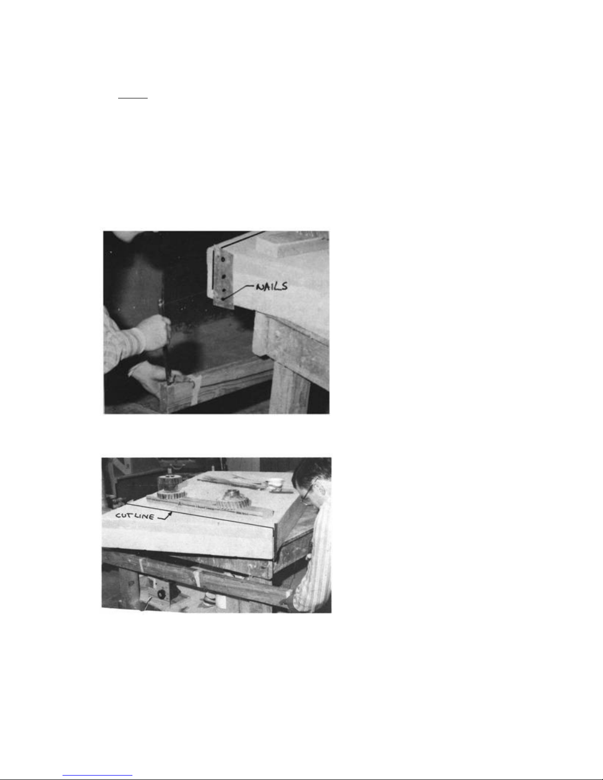
.....Preparing a foam block for an airfoil cut is begun by trimming
the rectangular foam block to the basic dimensions for the correct
planform. These "trim" cuts are made using two straight edged trim
templates. The templates are held against the foam by nails through
the template into the foam. Enough nails should be used to hold the
template firm so that it won't move when the hot wire is held against
it.
Cutting straight down along template
with a hotwire.
Note the diagonal cut being made by
correctly positioning the vertical
templates and passing the hotwire
downward along them.
..... Each template must have holes for nails to hold the templates
to the foam; four penny nails are good for this use. The holes in the
Page 42
templates should be a close fit for the nails. Be careful not to
angle the nails so that the hot wire can catch on them! Some rib
templates are used several times, for both inboard and outboard,
requiring you to transfer the talking numbers, pause marks, trim
line, and waterline to the opposite side of the template.
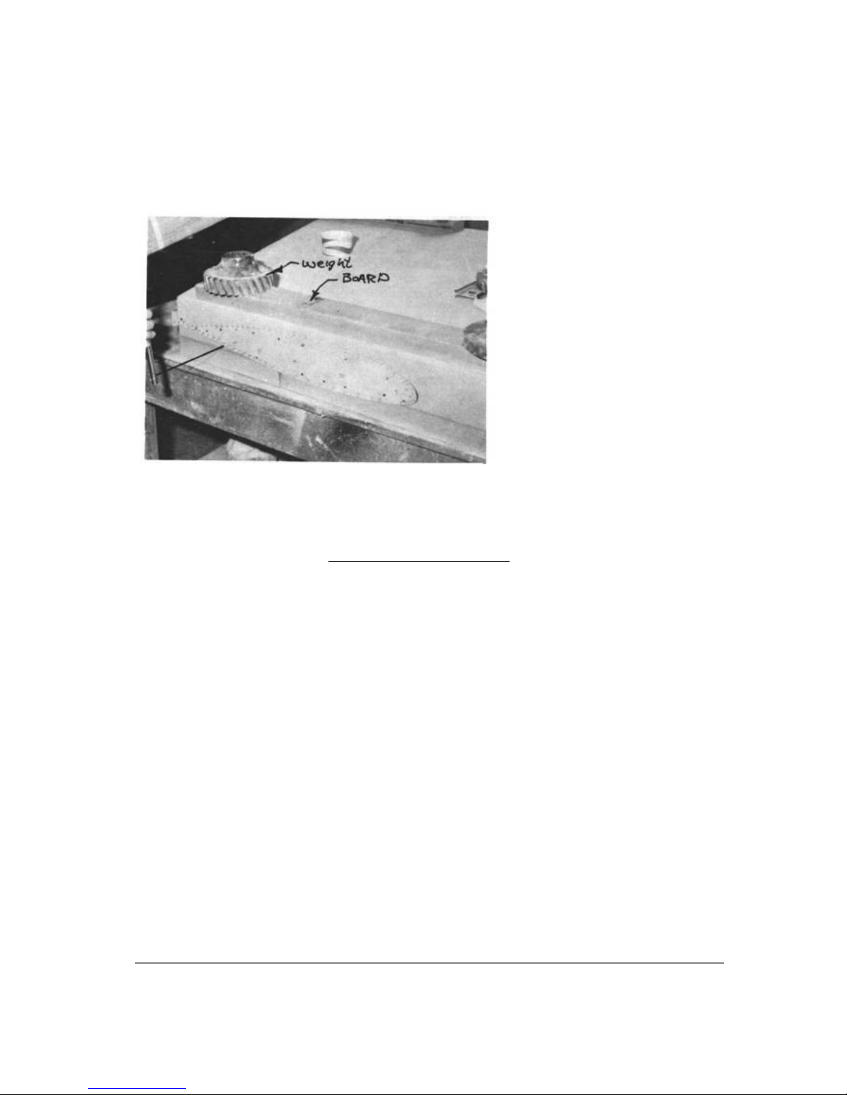
Support the foam block well; don't overhang
the block past the edge of the jigging
table.
CONTINUED ON NEXT PAGE
PAGE 3-6
Page 43

Q2 Plans - Chapter 3 - Page 3-07
..... The use of the hot wire saw is a simple thing if your equipment
is set up properly. Proper wire tension and wire temperature should be
maintained for good cutting. The wire tension should be tightened
after the wire is hot by twisting one tube with a pair of pliers. The
wire should be as tight as possible. The wire should be hot enough to
cut one inch of foam in four to six seconds without having to force
the wire. A wire that is too hot will burn the foam away excessively.
To cool an over-heated wire, simply turn your voltage control to a
lower voltage setting. If you use a battery charger, you will have to
add length to the wire. To warm up a cool wire, just increase the
voltage setting or, with the charger, shorten the wire. Although the
foam offers only mild resistance to the hot wire, a long cut will
cause the middle of your wire to lag behind the ends. Wire lag can
cause problems in tight curves like the leading edge of an airfoil. To
reduce lag there, the cutting speed is reduced to about one inch in 8
to 10 seconds. The airfoil templates have notations in the areas where
reduced speed cutting is necessary and pause marks where it is
necessary to allow the lag to catch up completely.
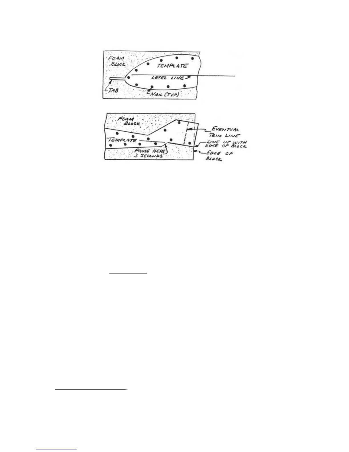
.....The most common hot wire error is wire lag which causes a bow in
the leading edge. The following method solves this problem and thus we
recommend you use it for cutting the canard and wing. Use the tabs on
the templates at the waterline at the leading edge by cutting the core
in two passes: one from the leading edge up over the top to the
trailing edge, the other from the leading edge (under the tab) down
under to bottom to the trailing edge. The thin flashing of foam left
on the leading edge due to the thickness of the tab is easily removed
with your butcher knife. The result is a perfectly straight leading
edge. Care must be taken to assure that both ends simultaneously
approach the template at the leading edge. Use the following vocal
commands “wire is moving toward the tab, now resting on the tab 1/2
inch from the template (confirm both ends in that position), moving
toward template 1/4 inch away, 1/8" away, on the template, moving up
(talking number), Y (talking number)...” When approaching the trailing
edge overlap notch (see sketch) slow down and pause 3 seconds in the
notch to assure a full, sharp, accurate surface for the skin overlap.
Page 44
..... The hot wire should be guided around the templates with light
pressures. Pushing too hard against the template may move them or flex
the foam block which results in an under cut foam core.
.....The correct set-up is just as important as using the correct
tools and materials. Foam is a fairly flexible material and an
improper set-up can cause deflection. The foam block should be well
supported at each end, so that it doesn't sag and doesn't move around
while being cut.
.....You need clearance for the hot wire cutter to pass by the table
and the weights used to hold the foam steady.
.....Foam is manufactured in sizes that are often too small to get a
complete core from a single block. it is necessary to use two foam
blocks to get the size required for the wing cores. These blocks have
to be joined using an epoxy/microsphere mixture. The hot wire won't
cut through the micro joint, so all of the hot wire cutting is done
with the blocks temporarily joined. Nails or blobs of 5-min epoxy are
used for temporary foam joints, but the hot wire won't cut through
these. Thus, they have to be placed carefully so that the wire doesn't
have to pass through them.
.....Don't be overly concerned if you don't make perfect foam cuts:
ridges on the foam core from inadvertently lifting the hot wire off
the templates are easily faired in with a sanding block. A less-thanperfect leading edge can be blended in by sanding after the foam core
is assembled. Gouges in the foam can be smoothed and filled with dry
micro to contour after applying the glass skins. The foam is too
expensive to throwaway because of a minor gouge.
.....A finished foam core may warp out of shape after it is removed
from the original rectangular block. This is due to internal stresses
in the foam from the manufacturing process, and is no cause for
concern.
.....A warped core is simply weighted into the jig blocks and shimmed
straight prior to glassing. Once the skin has been installed, the foam
is held firmly in position by the sandwich structure.
URETHANE FOAM SHAPING
..... One of the real treats in the construction will be shaping and
contouring urethane foam. Urethane is a delightful material that
Page 45
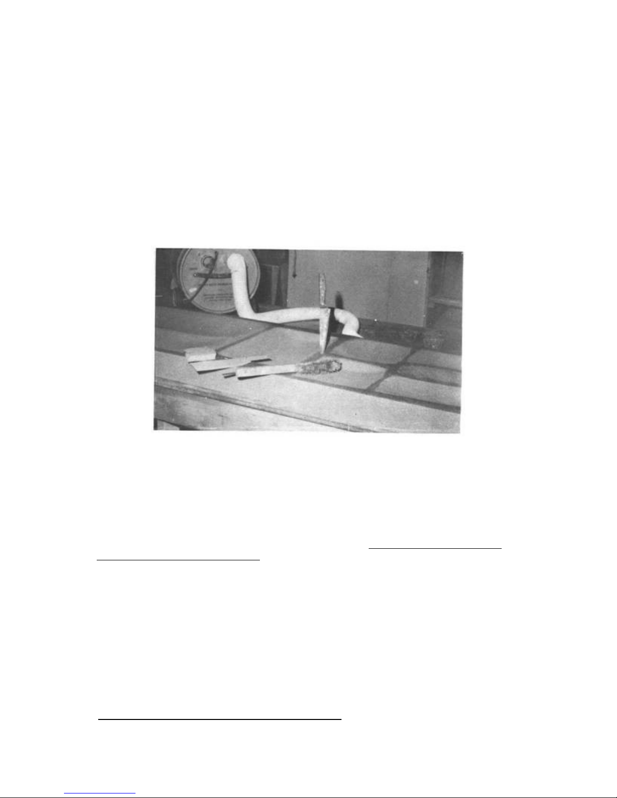
shapes with ease using only simple tools. A butcher knife, old wire
brush, sandpaper, and scraps of the foam itself are the basic urethane
working tools. A vacuum cleaner is convenient to have handy since
working urethane produces a large quantity of foam dust.
.....The knife is used to rough cut the foam to size. The knife needs
to be kept reasonably sharp; a sander or file is an adequate knife
sharpener since it's a frequent task and a razor edge isn't necessary.
Coarse grit sandpaper (36 grit) glued to a board is used for rough
shaping.
.....Inside contours or "dishing" is done by using a ragged old wire
brush to rough out the bulk of the foam and following up with a scrap
foam piece to smooth the surface. The foam scrap conforms to the shape
of the surface resulting in a very smooth contour.
..... Outside contours are roughed out with a sanding block and
finished using a foam scrap. Dry micro and flox are used to fill voids
and pot fasteners in a number of places. All foam shaping should be
finished before any micro filling is done, because the filler is much
harder than the foam and this makes smooth contouring very difficult.
Your best carving template is your eyeball; an occasional check on the
depth of a contour is about the only measurement necessary.
.....Keep your shop swept reasonably well. The foam dust can
contaminate your glass cloth and your lungs. Use a dust respirator
mask while carving urethane. Try not to aggravate the better half by
leaving a green foam dust trail into the house.
PAGE 3-7
Q2 Plans - Chapter 3 - Page 3-08
Page 46

GLASS LAYUP
..... The glass layup techniques used in your Q2 have been
specifically developed to minimize the difficulty that glass workers
have traditionally endured. The layups that you will do will be on a
flat horizontal surface without the molds, vacuum bags, and other
special equipment that are common in glass work. The layups that you
do will all cure at room temperature; no ovens or special heating is
required. If you have suffered through a project that requires you to
build more molds and tools than airplane components, then you are in
for a real treat.
.....The techniques that you will use are quick but they still need to
be done correctly. 90% of the work that you will do is covered in the
next few paragraphs so make sure that you read and understand this
section very well. If you learn these basics, your airplane will be
easy. If you skip over this information, you will probably end up
frustrated.
STEP 1: PERSONAL PREPARATION
..... Before you get started with a layup, plan ahead. Some major
layups take several hours and before getting your hands in the epoxy,
it's a good idea to make a pit stop at the restroom.
.....Do not start a large layup if tired; get some rest and do it when
fresh. It's best to have three people for any large layup; two
laminators and one person to mix epoxy. Be sure that the shop is clean
before you start.
.....Take the recommended health precautions (discussed later in
detail) using gloves or barrier skin cream. Get your grubby, old
clothes on or at least a shop apron. Make sure that your tools are
clean from the last layup and ready to use. Your working area should
be between 7O°F and 90°. Best results are obtained at 75 to BO°F.
Below 7O°F the epoxy is thicker making it more difficult to wet the
cloth. Above 90°F, the possibility of an exotherm is greater.
STEP 2: CUT FIBERGLASS CLOTH
..... The fine points of glass cutting have been covered earlier.
Remember that there isn't any requirement to cut accurate dimensions.
Cloth dimensions are given well oversize. You scissor trim them as you
go, while laying the cloth up. It is a good idea to keep two pair of
scissors: one clean and in the glass storage area, and one in the shop
that gets epoxy on it. After cutting, roll or fold the material; keep
it clean and handy for the layup.
STEP 3: PREPARE SURFACE
..... The only difference between 1ayups over different materials is
in surface preparation. The layup over foam will be covered here since
you will be doing more of it, and other surface preparations will be
covered separately.
.....The foam surface is prepared by leveling uneven areas with a
sanding block and brushing or blowing any dust off the surface. Use
compressed air or vacuum to remove dust.
.....Now is the time to accurately check that the foam core is the
correct size, shape and contour. Refer to the section views of the
Page 47
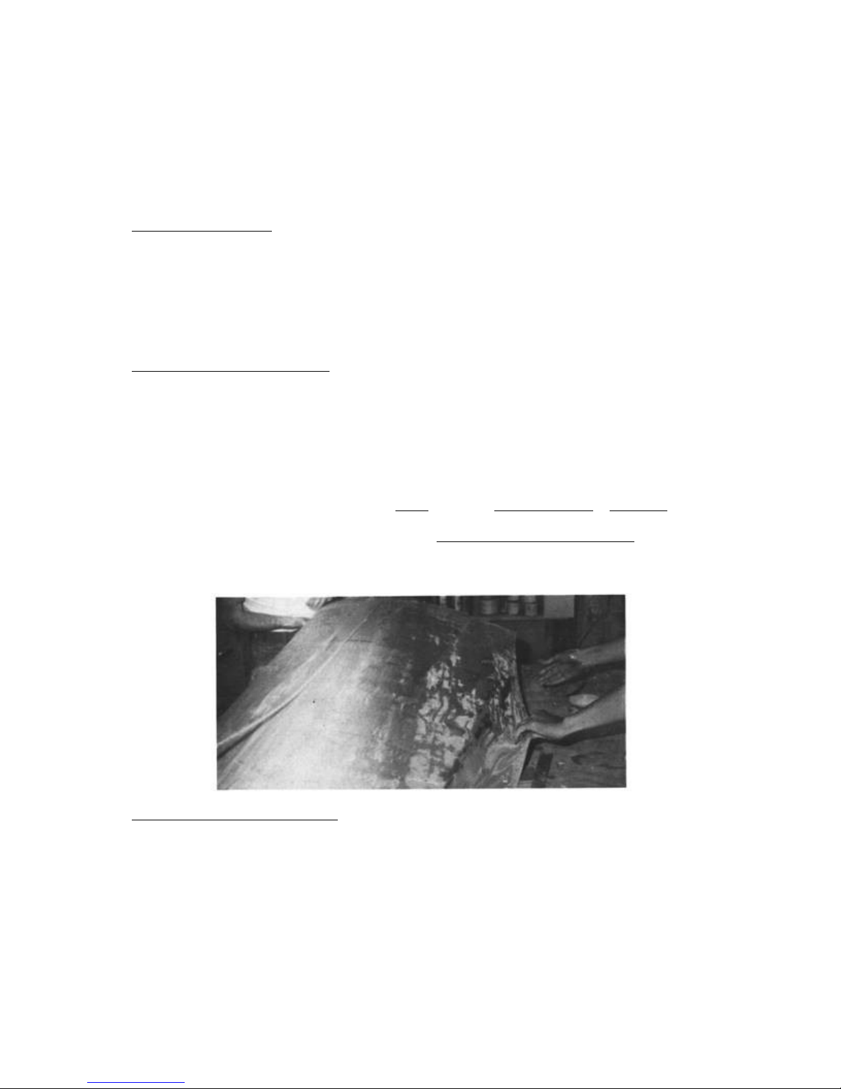
part - be sure your core looks exactly like that on the section view.
Lay a 12 inch straightedge spanwise on all critical areas of the
flying surfaces and be sure you don't have any high or low places or
joggles. Measure any areas that involve fiberglass buildups to check
for correct depth. Build up is 0.009 inch per ply for UNI and 0.013
inch per ply for BID.
STEP 4: MIX EPOXY
..... Mix epoxy when you need it, not before. Micro, dry micro, and
flox may be required at various stages of the layup. Mixing and
composition details were covered earlier. Apply a coat of micro slurry
to the foam surface before the first glass ply is laid over it. The
slurry can be poured on the foam and spread thin with a squeegee. Fill
any dings or gouges in the foam core with dry micro prior to applying
the slurry.
STEP 5: LAY ON THE CLOTH
..... Lay on the cloth in the specified orientation. Pull the edges to
straighten the cloth out and to remove wrinkles. Maximum strength and
stiffness is obtained if the fibers are not wavy or wrinkled. If the
cloth is to be applied around and/or into a sharp corner, you will
find the job easier to do if the fiber orientation is at 45° to the
corner. Don't get depressed if the layup looks like a hopeless mess at
this point. Press on with patience and things will work out fine. To
remove wrinkles, study the direction of fibers, follow the fibers to
the outer edge of the cloth and pull on the outside edge. Pushing a
wrinkle off the part is incorrect. Once the part is free of wrinkles
use a squeegee and make light passes from the center outwards to
smooth the cloth.
STEP 6: WET OUT THE CLOTH
..... Do not use micro between plies of cloth. Wet out the cloth by
pouring on a thin coat of epoxy. This may not be necessary if there is
enough epoxy under the cloth to be brought to the surface. This is
done by "squeegeeing", which involves drawing the squeegee over the
cloth. This brings excess epoxy up from be¬ low to wet out the cloth,
resulting in a weight savings as compared to adding more epoxy on top.
REMEMBER, epoxy adds no strength beyond what is needed to wet out the
white color of the cloth and fill air voids; any further addition of
epoxy is only dead weight.
.....Where multiple plies are required, the first plies may be laid up
Page 48
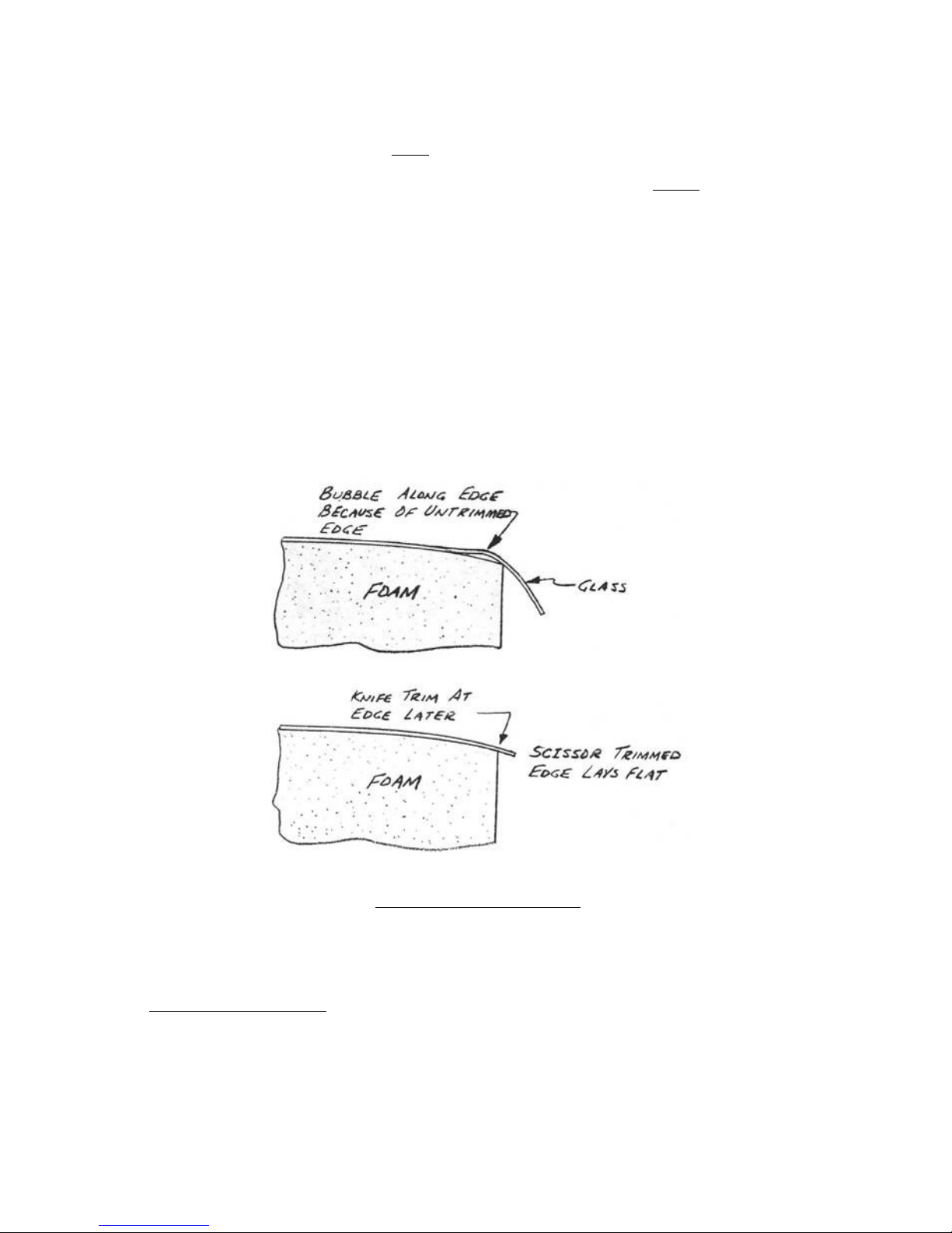
wet and the excess resin brought up by squeegeeing to help wet out the
middle plies. To do this, pour epoxy onto the part and move it around
the surface with a squeegee. Your work will go much faster if you make
the layup too wet, then remove excess epoxy with many light passes
with the squeegee. Do not squeegee too hard, as this can starve the
surface of micro and introduce air. Continue to inspect for air (tiny
white flecks or bubbles) and stipple (a vertical stabbing motion with
a paintbrush) or squeegee in more epoxy to remove the air. A handy
squeegee can be cut from the flexible plastic found on a coffee can
lid. You may also find a paint roller handy for spreading around the
epoxy. The final plies are ambitiously stippled and additional epoxy
is applied sparingly. When in doubt - squeegee it out.
.....As you wet out each ply, scissor trim to within 1/2" of any
overhang (trailing edge, etc.). This 1/2" will be knife trimmed after
the layup cures. If an overhanging ply isn't trimmed, it lifts the
edge up and makes a bubble.
.....After scissor trimming, restipple the edges to be sure there are
no voids. Wet the cloth beyond the trim line at least 1/4" to allow
easy knife trimming later.
STEP 7: SQUEEGEEING
..... Squeegee out excess epoxy. This involves drawing a plastic or
rubber squeegee over the layup as shown. Plastic squeegees (scrapers) are
available at any paint store and included with the kit. If excess epoxy
exists, it will be pushed off the edge of the piece. Remember, excess
CONTINUED ON NEXT PAGE
PAGE 3-8
Page 49
epoxy is much better on the floor than on the airplane. It is possible to
squeegee too hard and make the layup too dry. If this occurs, the surface
will appear white, indicating the presence of air. If this occurs, wet
the cloth by painting on a little epoxy and stippling it down into the
layup. The best quality layup is obtained if each layer of a multilayer
layup is squeegeed. The excess epoxy which is pushed off the edge can be
recovered and returned into the cup. This is easily done by catching the
epoxy on the squeegee and scraping it on the side of the cup.
.....The finished layup should appear smooth and green so that the weave
of the cloth is clearly visible, but not so dry that any area appears
white in color. If you've done an excellent job, the weight of resin will
be about 2/3 of the weight of cloth used.
.....To check if there is too much epoxy in the layup, pull a squeegee
across the surface, stopping before you reach the edge. Lift the squeegee
up and look for a large "ridge" of epoxy where the squeegee stopped. The
ridge under the top ply indicates that the layup is too wet and you
should spend time with the squeegee to remove epoxy off to the sides.
.....Don't hesitate to use your stippling roller or brush on an area
after squeegeeing. Some places are not suited to the use of a squeegee
and the dry brush or roller must be used to expel the excess epoxy. On a
given layup, about 1/2 of your time should be spent squeegeeing or
stippling.
STEP 8: GENERAL INSPECTION
..... After you have finished the layup, take a few minutes and give it a
good general inspection for trapped air, dry glass, excess epoxy, and
delamination. It is much easier to correct these things while the layup
is wet than to repair the cured layup. Also, have someone else inspect
it. Usually a different person can find air flecs or bubbles that are
missed by one inspector. Carry a good light around for the inspection.
Glance the light off the surface at various angles to look for airflecks.
If any air is visible, stipple it out. Be sure the overlaps on the edges
are perfect. If, due to a sharp corner etc, you have a problem
eliminating an air bubble, use one of the following two methods:
1. Lift the cloth up off the foam, trowel some wet micro
into the troublesome area, add more epoxy as you
stipple the cloth back down.
2. Add excess epoxy over the bubble, cover the surface
with saran wrap (thin plastic wrap), then push firmly
outwards to force the air out to the sides. The saran
wrap will seal the surface to keep air from being drawn
in. This method will force the cloth to stay down even
Page 50

around a sharp corner.
STEP 9: PRELIMINARY CONTOUR FILL
..... Certain areas, like along the trailing edge (see cross section
views) require a dry micro fill. It is preferred to apply this fill
within 2-3 hours of finishing the fiberglass layup. However, where the
micro filler obscures the structure underneath, FAA inspection should be
completed before dry micro filling. Areas like the trailing edge where
the structure can be inspected from the other side should be filled while
the layup is still tacky (within three hours of the layup). If you wait
until the layup cures, you will have to sand the fiberglass surface to a
dull finish before applying the micro. So, mix up a "dry" micro mix and
trowel it into low areas while the layup is still wet, and save the work
of sanding where feasible.
STEP 10: CLEANUP
..... Brushes can be used two to four times if after each layup they are
washed with soap and water. Wipe excess epoxy off with a paper towel. Wet
the brush and work soap into all fibers by mashing it into a bar of soap
(Lava brand is best). Rinse with hot water and repeat 3 times. Be sure
they are dry before next use. We generally use a cheap brush
(approximately $2.00 to $4.00 per dozen) and discard after two or three
layups. Clean squeegees the same way.
.....If you use skin barrier cream (Ply No.9), the epoxy and cream will
wash off easily with soap and water. When you get epoxy on unprotected
skin, Epocleanse is used to remove the epoxy. Both of these products are
available. Once you are sure your skin is clean, wash again thoroughly
with soap and water, even if your hands were protected with plastic
gloves. If you get epoxy on tools or metal parts, clean them with acetone
or MEK before the epoxy cures. .
.....The only good way to protect your clothing is not to get epoxy on
anything that you care for. Use a shop apron and don't make layups in
good clothing. A surplus flight suit or other cheap coveralls are a good
investment.
.....You may feel that layups are messy work after your first experience
with them. However after you've done several, you will have learned not
to wipe your hands on your clothing (keep a roll of paper towel's handy),
not to scratch your ears, eyes, etc. during the layup. If your tools and
work area are clean and organized well and you are disciplined with the
epoxy, the job can be less messy than working with other materials.
STEP 11: KNIFE TRIM
..... When a layup is wet, you can only scissor trim to within about 1/4
inch without disrupting the fibers in the ply. An easy clean trim can be
obtained by waiting three to five hours after the layup. At this time,
the laminate is firm enough to support the cloth from fraying, yet soft
enough to cut easily with c sharp knife. This "knife trim" stage is the
optimum time for edge trimming with ease and accuracy. Take a sharp,
single-edge razor blade or X-Acto knife and trim the edges with a motion
downward toward the edge. Experience will help you determine the correct
time in the curing cycle for optimum knife trimming.
Page 51
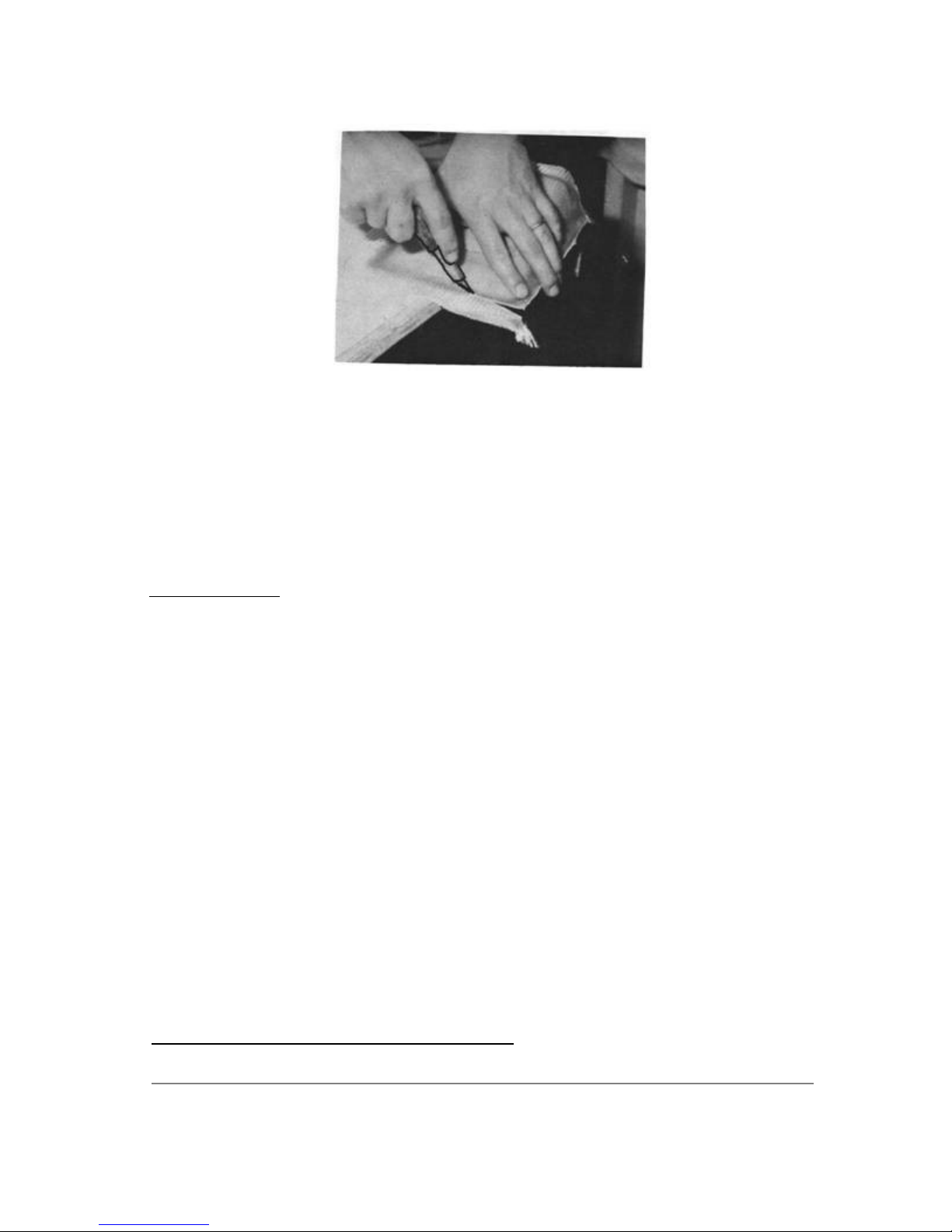
..... In the plans, when "knife trim" is called for, this assumes the
three to four hour wait, even though not specifically stated. Don't fall
apart if you miss the knife trim stage and have to trim the fully cured
glass. If you wait until the layup is completely set, then saw along the
edge with a coping saw, Dremel, band saw, saber saw, etc. Smooth the edge
with a sanding block. When trimming a cured edge, be careful of the
"needles" (sharp protrusions of glass-frayed edges supported with epoxy).
.....The needles can be avoided by returning three hours after the layup
to make the knife trim. Knife trim time varies with temperature: about
six hours at 60 degrees and one hour at 90 degrees.
OTHER SURFACES
..... Surface preparation (step 3 of the basic glass layup) varies with
the material that you are laying up over. The layup over foam was covered
in detail in step 3. To prepare a cured glass surface for layup, the
cured surface must be sanded to a completely dull finish with 36 to 60grit sandpaper. If any of the glossy surface remains, an incomplete bond
results which is weak. Better yet, use peel ply as described later, Micro
slurry should not be applied to glass surfaces being bonded; this weakens
the joint. Wood requires no special preparation for bonding but should be
free of grease, oil, paints, and varnish. Sand wood surfaces with 36-grit
sandpaper before layup. Metal bonding is not relied upon for strength but
PAGE 3-9
Q2 Plans - Chapter 3 - Page 3-10
Page 52
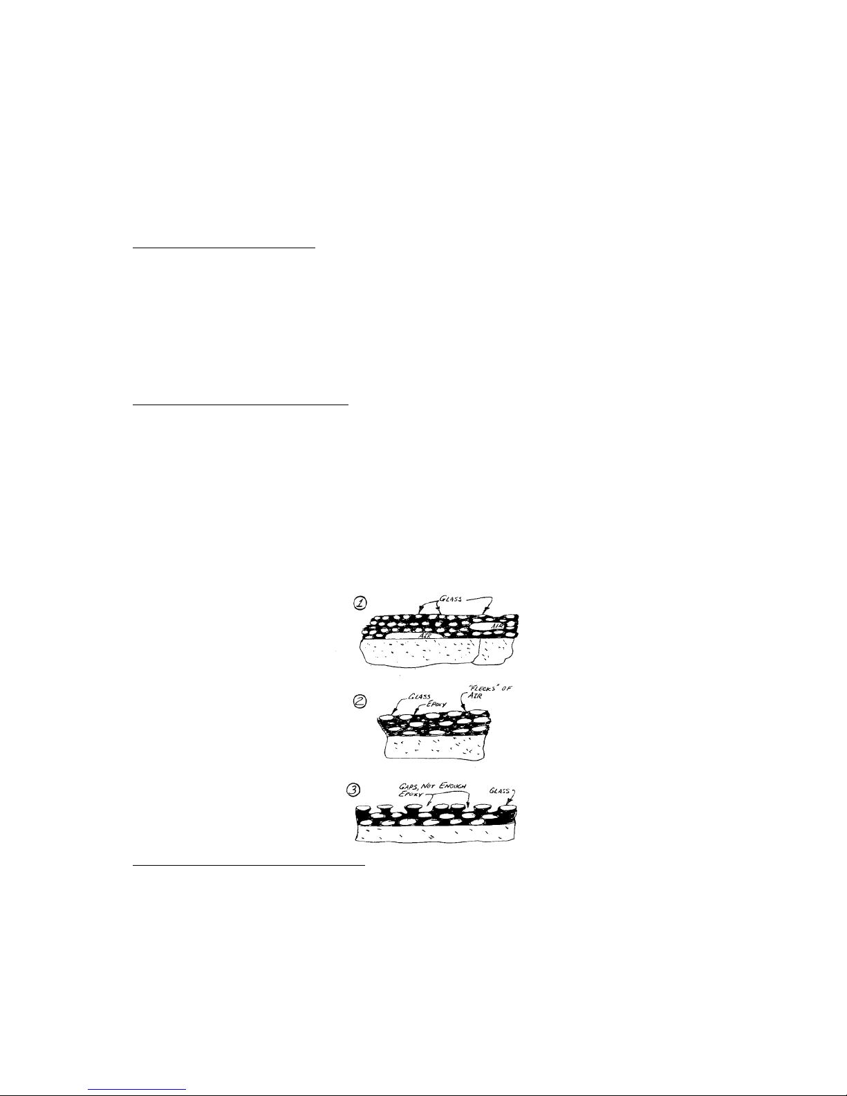
metal surfaces should be free of oil and grease and, except for bolts,
nuts, and other fasteners, metal surfaces should be dulled by sanding
with 220-grit sandpaper, and coated with epoxy before setting in place.
Cured micro surfaces should be sanded dull but be careful not to
obliterate surrounding foam surfaces while doing it. In practice you may
be glassing over several types of material in the same layup and you will
be using most of these surface preparation techniques together.
ATMOSPHERIC CONDITIONS
..... Temperature has the greatest effect on the working properties of
your epoxies. 75 degrees Fahrenheit is an ideal temperature. The range
from 60 to 90 is acceptable with the precautions mentioned in the section
on EPOXY. Humidity has a lesser effect on these materials than it does on
aircraft dopes and some paints. Humidity will only create problems if it
is over 75%. Don't undertake a layup if it is pouring down rain outside
or, if you notice a cloudy "blush" on the wet epoxy surface, or any
evidence of whiteness in the epoxy due to moisture.
RECOGNITION OF A DRY LAYUP
..... One of the most important things you must know is how to inspect
for the presence of air within a layup. Air leaves somewhat crystal-like
flecks of white areas, noticeably different than the white color of the
microballoons. The presence of air is shown in the adjacent sketches in 3
forms: (1) A bubble or large void at the foam surface or within the
laminate, (2) small bubbles of air scattered throughout an area, or (3)
inadequate filling of the outer ply. Make a layup of 3 ply BID in a 6inch square over a scrap piece of foam, trying to achieve these 3 types
of dryness. Let it cure with the defects. This will be a handy sample to
use to instruct others who will help you inspect.
DRILLING, GRINDING, & SAWING
..... Drilling through cured glass tends to tear the surface plies on the
back side. Backup a glass layup with a wood block for drilling as shown
and drill at medium speed.
Page 53
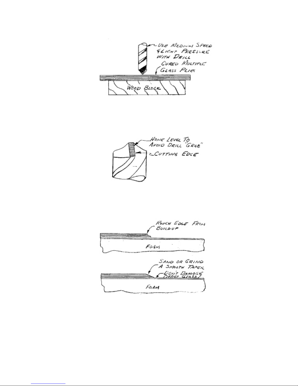
.....Using a small hone, grind the cutting edges of your drill bit flat
as shown (not undercut). This will keep the drill from grabbing into the
glass. Don't over-do it, just make a couple of light passes with the
hone.
.....In several places rough, cured glass surfaces occur where overlaps
or thick buildups are done. These rough edges should be smoothed as shown
using a grinder or sanding block.
.....The Dremel (Moto Tool) or Home Shop (Weller) is a very versatile
tool with many uses in the construction of your Q2. The kits usually have
a nice selection of bits, cutters, grinders, stones, and mandrels for
every conceivable use. The three types of bits shown here are the most
useful for your project. Don't throw the others out, as your next door
Page 54
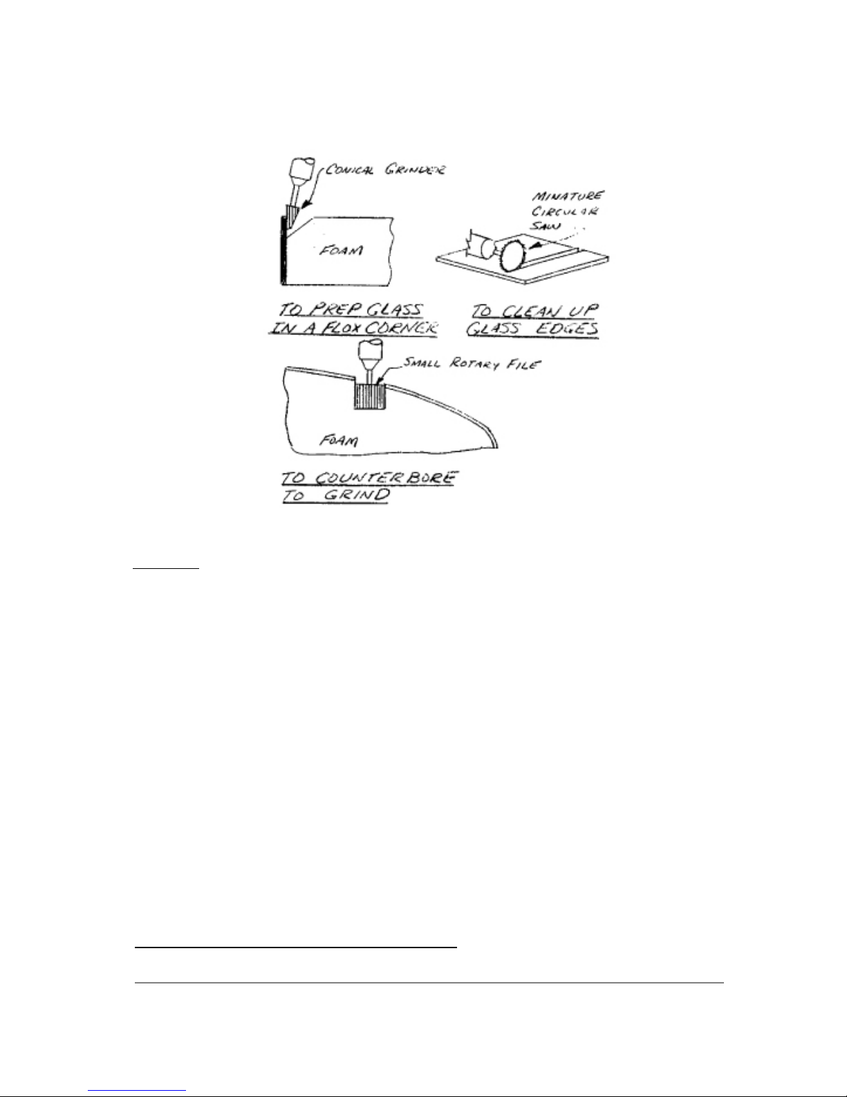
neighbor might be able to use them on his supersonic ornithoper project.
RIVETING
..... A pneumatic riveter is not required. The few hard rivets used can
be set with a hammer, using your vise as backup. The 'pop-type' rivets
are pulled with a low-cost hand puller available at any hardware store.
Q2 Plans - Chapter 3 - Page 3-11
Page 55
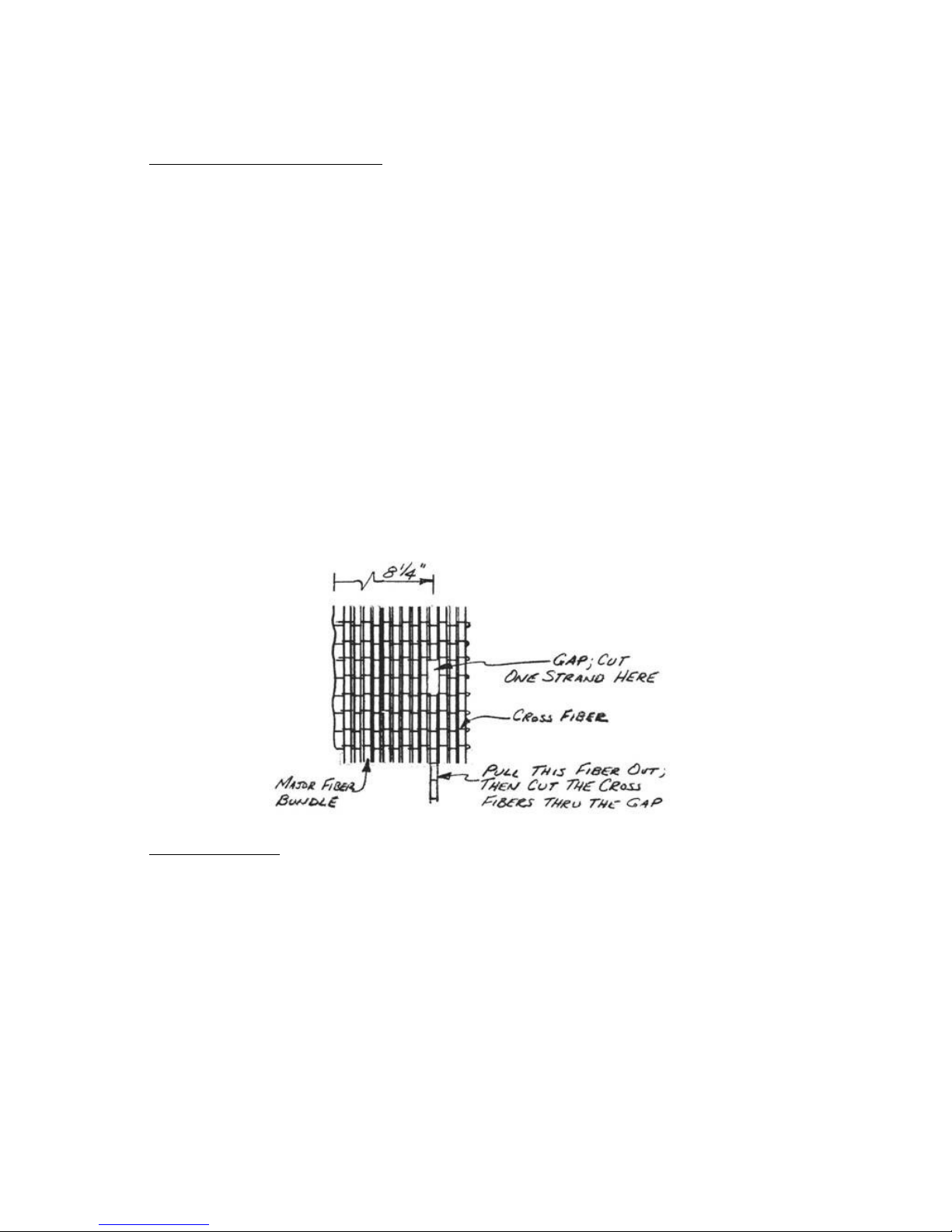
CUTTING THE UNI SPAR CAPS
..... The spar caps used in the main wing, vertical tail, and canard,
are strips of UNI cloth that you will cut from the roll provided in
the kit. Begin by unrolling the roll on a long, flat surface. The
example to be used here will be a spar cap A that is 8" wide by 50"
long. You would measure a 8-1/4" wide piece (to allow for frazzling
of the edges) by 50" long, with the fiber orientation running along
the 50" edge.
.....The technique is one of finding the one strand that is at the
edge of the 8-1/4" width, cutting it, and then pulling that whole
strand the length of the spar cap to remove it. You will now see a
clearly visible gap in the UNI cloth where that one strand used to
be. Now, using an Exacto knife or razor blade, cut all of the cross
fibers along that gap, thus severing the spar cap from the rest of
the roll.
.....Carefully mark the cap with a centerline (in this case at the
25" point, mark it with the letter A and roll it up to keep dirt out
of the fibers. When you next unroll it, you will probably find that
the edges are frazzled. As long as you don't reduce the width below
the original callout (in this case 8") you may pull off strands that
are frazzled. Be careful to only pull loose one strand at a time or
else the whole spar cap will start coming apart!
GLASS-TO-GLASS
..... In order to improve the rigidity of a part, you will
occasionally be asked to perform a glass-to-glass layup, sometimes
abbreviated as GTG.
.....The example shown here is a glass-to-glass layup on a bulkhead.
Begin by glassing one side of the bulkhead as usual. Next, having
turned the bulkhead over after curing to prepare the other side for
glassing, you will remove foam with a smooth transition so that your
next layup will butt up against the previous glass layup.
.....
The amount of "overlap" necessary varies with the loads. On
bulkheads, use a minimum of 3/8", on the trailing edges of ailerons
and elevators use 1" minimum, and on the trailing edges of the wing,
use 3/8" minimum.
Page 56
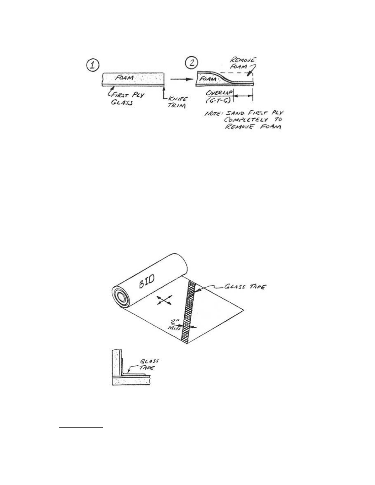
PHENOLIC BONDING
..... Before bonding phenolic to any surface, be sure to sand the
phenolic dull (i.e. to remove the shiny surface) immediately prior to
doing the layup. This avoids getting grease from your hands, etc. in
the layup, which might cause poor adhesion and subsequent failure of
the layup.
TAPES
..... Quite often during the construction of your Q2, you will be
asked to use glass tapes to join two pieces together.
.....A glass tape is a strip of BID cut at 45 degrees which is used
to lap up onto both surfaces that are being joined. For proper
strength, the tape should be at least 2" wide.
INTRODUCTION
..... One of the unique features of the glass-foam-glass composite
QUALITY CONTROL CRITERIA
Page 57

construction technique is your ability to visually inspect the
structure from the outside. The transparency of the glass/epoxy
material enables you to see all the way through the skins and even
through the spar caps. Defects in the layup take four basic forms:
resin lean areas, delaminations, wrinkles or bumps in the fibers, and
damage due to sanding structure away in finishing. Resin lean areas
are white in appearance due to incomplete wetting of the glass cloth
with epoxy during the layup.
DRYNESS CRITERIA
..... Pick any 6"x6" square in the layup in the critical area. Assess
carefully if any evidence of air in the layup is present (white
flecks, bubbles, air at the foam face). If the dryness is more than
10% of the area, the part MUST be rejected. Reject or repair any
evidence of dryness or voids in the trailing edge or leading edge
overlaps. Better yet, do an adequate inspection with good light
before cure when it's easy to fix. If in doubt on overlaps be sure to
stipple in enough epoxy.
.....Delaminations in a new layup may be due to small air bubbles
trapped between plies during the layup. The areas look like air
bubbles and are distinctly visible even deep in a cured layup. Small
delaminations, or bubbles up to 2-inch diameter, may be filled with
epoxy by drilling a small hole into the bubble and filling the void
with epoxy.
.....When making a layup, do not be concerned if the brush
occasionally sheds a few bristles; these do not need to be removed.
If the bristle count exceeds about 10 per square foot, change your
brush and remove bristles.
.....Occasional sanding through the weave in the first skin ply is
not grounds for scrapping the part. Care should be exercised in
areas, such as the skin joints, not to weaken the structure in
pursuit of an optimum finish. An excess of resin (wet) will make your
airplane heavy and does weaken the layup, but usually not enough to
reject the part for strength reasons.
BUMP/JOGGLE/DIP CRITERIA
.....The best way to check this is to lay a 12-inch straightedge on
the part spanwise. Move it allover the surface in the critical areas.
If you can see 1/16" gap in any area, the part must be repaired. It
is best to repair or beef up lumpy areas even if they meet this
criteria. Better yet, do a good job in core preparation and use your
squeegee well in the lay up to avoid the lumps in the first place.
PAGE 3-11
Page 58
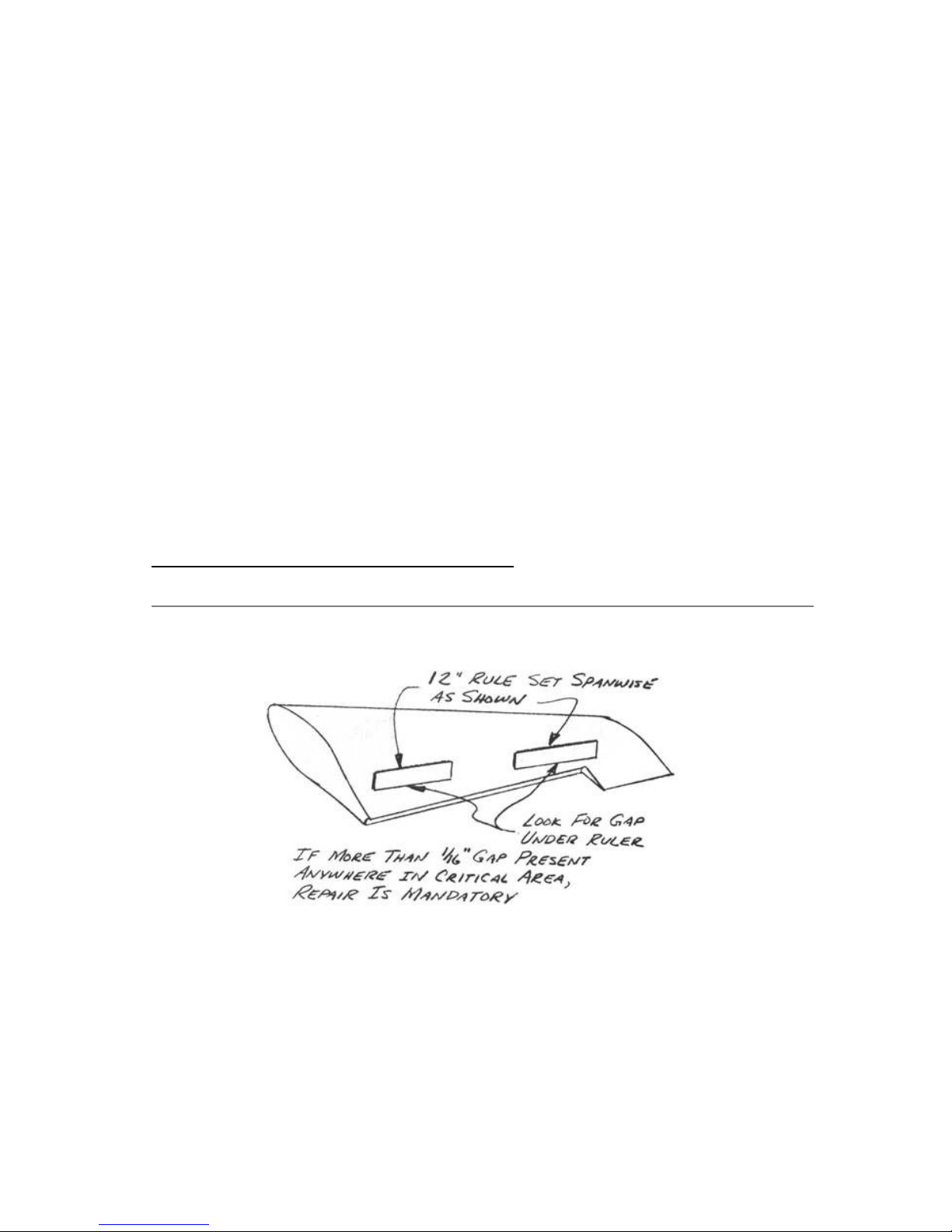
Q2 Plans - Chapter 3 - Page 3-12
..... The following is a listing of the "critical areas"; the
portions of the Q2 that must meet all the inspection criteria:
1. Entire canard.
2. All portions of the fuselage within 10" of
the engine mounts, canard, and wing.
3. All control surfaces.
Page 59
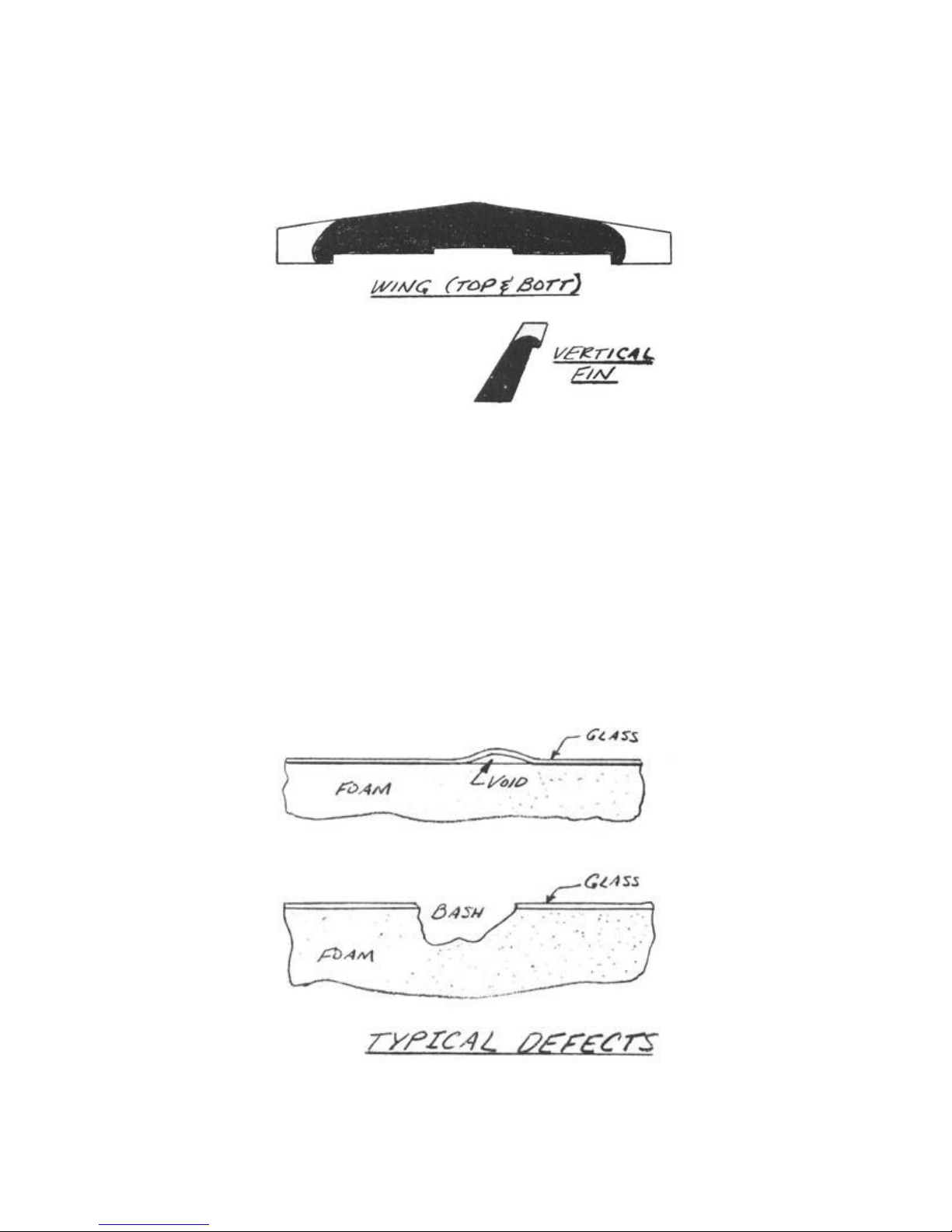
4. All flying surfaces in the shaded areas
shown, plus all overlaps at L.E. & T.E.
..... Major wrinkles or bumps along more than 2" of chord are cause
for rejection in the wings, canard and vertical fin, particularly on
the top (compression side). This does not mean you have to reject the
whole wing - anything can be repaired by following the basic rule:
remove the rejected or damaged area and fair back the area at a slope
of 1" per ply with a sanding block in all directions. By watching the
grain you will be able to count the plies while sanding. Be sure the
surface is completely dull, and layup the same plies as you removed,
plus one more ply of BID over the entire patch. This will restore
full strength to the removed area.
.....Use this method to repair any area damaged for any reason -
inadvertent sanding through plies during finishing, taxiing a wing
into a hanger, etc.
Page 60
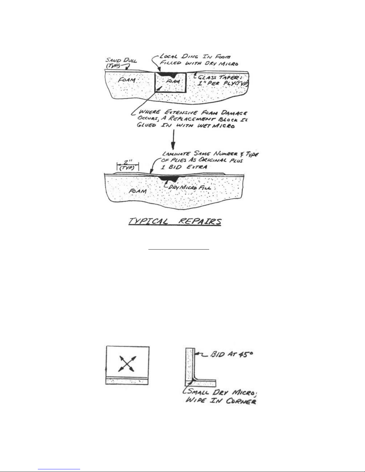
CORNER TREATMENTS
..... A variety of structural corners are employed in the
construction.
......There are two basic types of corners: one where the glass
fibers are continuous around the corner, and the other where a
structural filler is used and glass is bonded to the filler. The
corner with the glass fibers running completely around it is used
where maximum strength is required.
......Inside corners can be laid up quite abrupt and only a very
slight wipe of dry micro is needed to get the glass to lay into it.
BID cut at 45° is used on this type of corner.
Page 61
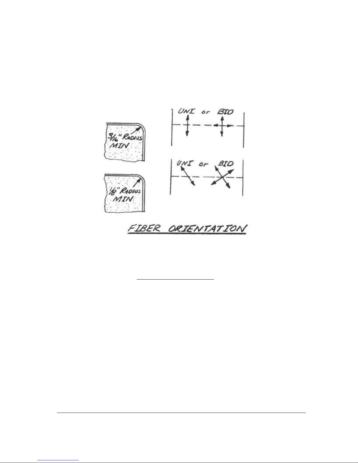
..... Outside corners require a radiused edge. Where the glass fibers
run directly around the corner a minimum radius of 3/16 inch is
required. Where the fibers run at an angle to the radius, only a 1/8
inch radius is needed.
CONTINUED ON NEXT PAGE
PAGE 3-12
Page 62
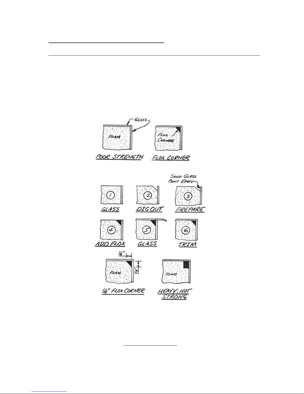
Q2 Plans - Chapter 3 - Page 3-13
..... In some areas a sharp corner is desirable and maximum strength
isn't required. In these areas a flox corner is used. A simple
unsupported glass corner has very poor strength. To strengthen this
corner, a triangle of flox is used to bond the glass plies together.
The flox corner is done just before one glass surface is applied for
a wet bond to one surface. The other glass surface has to be sanded
dull in preparation as shown.
HEALTH PRECAUTIONS
Page 63

SKIN PROTECTION
..... If you work with epoxy on your bare skin, you can develop an
allergy to it. This "sensitization" to epoxy is an unpleasant
experience and is to be avoided. You generally have to get epoxy on
your unprotected skin to become sensitized. If you use a protective
barrier skin cream like Ply No.9, or disposable plastic medical
examination gloves, the allergy can be avoided. The barrier skin
cream also allows you to clean up with soap and water after a layup.
.....The Safe-T-Pox epoxy systems are very low toxicity. However, a
few people (about 1 percent) may be sensitive to epoxy. These people
can get some help by using doctor prescribed anti-allergy medicines
and/or by using elaborate masks/multi-gloves, etc, to reduce
exposure. Remember to always use skin protection and never let epoxy
come in contact with bare skin, even if you have no reaction to it.
Sensitivity is accumulative, such that you may later develop an
allergy unless you protect your skin.
DUST PROTECTION
.....Sanding or grinding fiberglass and foams creates dust that can
be harmful to your lungs. Use a dust. respirator mask for these
operations. Disposable dust masks are available at most paint stores.
VENTILATION
.....Mix and work your epoxy in a ventilated area. If your shop is
not ventilated, set up a small fan to move a small flow of air in or
out. Do not hotwire urethane foam.
HEAT DEFORMATION AND CREEP
..... Several builders have had flying surfaces warp or bend due to
being poorly supported until fully cured. Do not hang or support them
at each end for long periods as they may "creep" or slowly deform.
Store them leading edge down with support in at least three places.
Your surfaces can be better protected against "creep" if you postcure them. Sailplane manufactures do this by putting the entire
airplane in an oven at 160°F. You can do it as follows: After you
have painted on the black primer put the wing or canard out in the
sun. Be sure it is well supported in at least three places along its
span. At noon a black surface can reach 140 to 180°F. giving it a
relatively good post-cure. After the post-cure, the structure is more
stable for warping or creep. If you have a wing or canard that is
twisted wrong, apply a twisting force in the opposite direction
before and during the post-cure (weights applied to boards, Bondo’ed
or clamped to the surface can be used). Remove the force only after
the surface has cooled. A 200 ft-lb torque (50 lb weight on a 4 ft
arm) applied twice, once while the top surface is post-cured and once
for the bottom, surface, can twist your wing or canard over one
degree. The twist correction will be permanent and will stay as long
as the surface remains cool (below the post cure temperature). This
is generally referred to as the heat-deformation characteristic of
the epoxy. If it is room-temperature cured only, it will soften above
140°F. But if post-cured it will not soften until over 160°F. Heat
for post-curing or for intentional deforming can be applied by other
means such as heat lamps, hair dryers or electric radiant heaters
(house-hold type), however this is generally not recommended, since
Page 64

it is too easy for the homebuilder to get the part too hot and ruin
the part. The foam is damaged above 240°F. If you want to use these
heat sources, do so by applying the heat very slowly and checking the
temperature often by placing your hand on the surface. If you can
hold your hand on the surface five seconds without pain, the
temperature is okay-three seconds is too hot.
AIRCRAFT MEASUREMENT REFERENCE SYSTEM
.....To ease the engineer's task of defining where things go in these
odd-shaped gadgets called aircraft, a fairly standard system of
references has been developed. Fortunately the Q2 is so simple that
an elaborate measurement system is not necessary. It is, however,
convenient to use the standard terminology for reference occasionally
and you should be familiar with its meaning.
.....The three basic references are called butt, lines, fuselage
stations, and water lines. Don't blame us for the absurd names, we
didn't set the system up. All three are given in inches from some
arbitrarily chosen reference, so, fuselage station 100 is found 100
inches away from fuselage station 0, and similarly for butt lines and
waterlines. Being as lazy as anybody else, we abbreviate these as FS,
BL, and WL.
.....Fuselage stations (FS) are used to define the location fore and
aft on an airplane. To make things easy, fuselage station a is
generally located near the nose of an airplane and measurements are
made aft. Fuselage stations are the most commonly used of the
references and later on you will make a reference mark on your
airplane to use as a permanent FS reference point.
.....Waterlines (WL) are used to define vertical locations. Waterline
0 is generally found near the ground and measurements are made up
from WL0.
.....Waterlines are utilized in many places to position components or
templates relative to each other by leveling reference waterlines
with a carpenters level.
.....Butt lines define positions inboard and outboard. Butt line 0 is
the vertical centerline of the airplane and measurements are taken to
the left and right of BL O. Since left and right depends on which way
you are facing, it is standard practice to define left and right as
the pilot would while seated in the cockpit.
.....Using these three references, any point in an airplane can be
described with a fuselage station, butt line, and waterline.
Fortunately, your Q2 is so simple that we don't need to locate very
many things this way. When you start on your 4/5 scale replica of a
B-1 Bomber, this reference system will be real handy.
PAGE 3-13
Page 65

Q2 Plans - Chapter 3 - Page 3-14
SURFACE FINISHING
INTRODUCTION
.....Finishing the composite airplane is more important than simply
obtaining an attractive paint job. The finish on a composite aircraft
serves to protect the structure from deterioration due to ultra
violet radiation (sunlight). The finishing materials also give the
airplane its final aerodynamic shape. Using the proper materials and
techniques, the finishing process is pleasing (both esthetically and
aerodynamically), and provides for long maintenance-free service. Use
of sub-standard materials can limit the life of the finish, result in
an overweight airplane, and even limit the service life of the
airframe. Sanding is done frequently during-the finishing process and
extreme caution must be exercised to avoid damaging the structure. A
poorly executed finishing job can destroy the structural integrity of
the airframe. Even the finished color of the composite aircraft can
effect its structure. The finishing process is as important to the
structure of the composite airplane as basic materials and techniques
used in fabrication are. Proper techniques must be adhered to for
safety as well as to obtain an attractive airplane.
.....The Q2 is sensitive to weight growth. You may easily add 50
pounds during the finishing process if you try to finish the entire
aircraft to sailplane standards (smooth, wave-free surfaces).
.....There is one part of the aircraft that must be finished to a
smooth and wave-free surface - the canard. We have found that unless
the canard is smooth and wave-free, serious degradation of
performance and flying qualities results. This section will tell you
how to obtain a smooth and wave-free finish on the canard.
.....The rest of the airplane, in order to keep it as light as
possible, should be sanded with very little filling, then primed. and
then painted. This will allow some of the fiberglass weave to remain
showing, but your Q2 will still look good.
.....Remember, build it light and finish it light; every pound of
weight that you save during the construction and finishing will make
the aircraft much more fun to fly in the coming years.
FINISH COLORS AND HEAT
.....The materials used in amateur-built composite airframes are
predominately epoxy resin systems with fiberglass reinforcement over
a variety of plastic foam cores. The epoxies and the foams are all
sensitive to high temperatures. Some epoxies, cured at elevated
temperatures, retain their physical strength to temperatures not
found outside an oven. Others, including most room temperature curing
epoxies such as the Safe-T-Pox system, soften and loose their
rigidity at only moderate temperatures. The common plastic foams are
also heat sensitive and. tend to soften and (some) swell with
moderately elevated temperature. Elevated temperatures could
potentially cause a softening of the fiberglass load bearing
material, a swelling of the foam core, and general distortion of the
airframe. To achieve elevated temperatures you would have to bake
your airplane or find some other means of heating it. The sun is a
Page 66
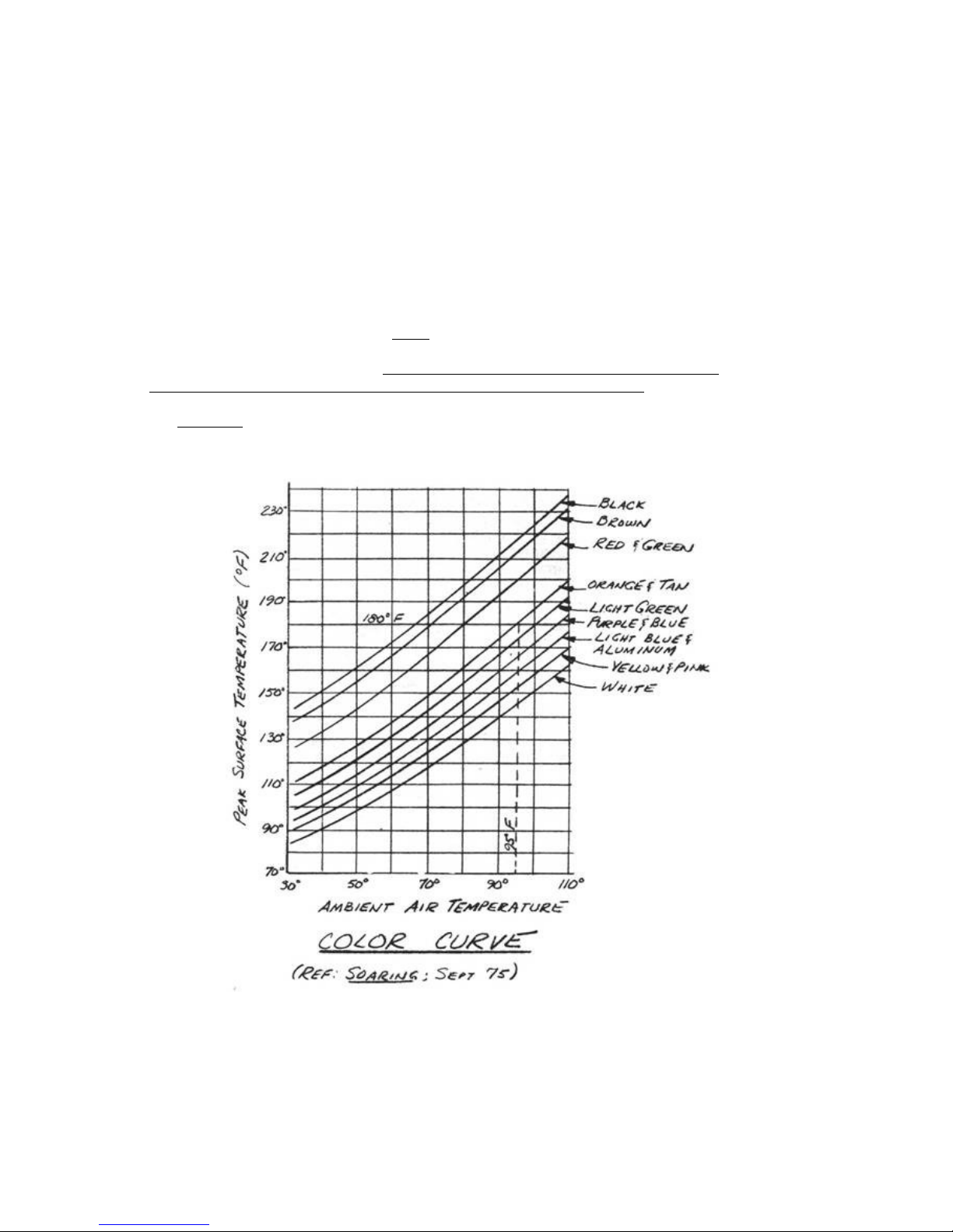
potential source for this heat. In still air, on a hot sunny day it
is possible to obtain surface temperatures that approach 250°F. The
color of the surface determines how much solar heat it will absorb.
White surfaces absorb very little (10%) of the sun's heat while a
black surface (95% absorption) will heat up tremendously.
The accompanying graph shows the relationship between color and
surface temperature. White has been chosen as the standard color for
fiberglass sailplanes to preclude any possibility of excess
temperature due to solar heating. The same criteria apply to the Q2,
and white is recommended. Trim colors in less-critical areas such as
the fuselage, vertical tail, and the underside of wings and canard,
can be other than white. Dark trim colors are definate1y not
recommended on the upper surface of wings and canard! If you would
like further information on the subject read the September 1975 issue
of Soaring magazine.
Page 67

TOOLS AND MATERIALS
..... The tools and materials used in finishing the composite
airplane are simple and straight forward. A low density
microsphere/epoxy mixture (dry micro) is used for coarse filling
requirements. Automotive type polyester body fillers (Bondo) are very
heavy and not recommended as a primary aircraft finishing material.
Medium to light surface filling (less than .030") is done with a
light weight polyester spray (or brush) filler/primer called FeatherFill. Feather-Fill is noteworthy for its ability to fill medium
thicknesses in a single spray or brush coat and for its easy sanding
to a smooth surface. Dupont 70S dark gray 1aquer primer/surfacer
provides an effective ultra violet radiation barrier with its 15%
carbon-black content as well as an excellent finish sanding surface
in preparation for the finish paint. The actual finish paint type is
largely a matter of the builder's personal preference. Automotive
finishes in laquer, enamel, acrylic 1aquers, acrylic enamels, and the
polyurethanes are all acceptable. We find the acrylic 1aquer is easy
to work with, easily patched, and readily polished to a high gloss.
.....The enamels and acrylic enamels are low cost and easy to apply;
however, they are not readily repairable if chipped. The polyurethane
finishes offer the best gloss for the longest life, but they are high
cost and virtually impossible to repair. There is a polyester paint,
known as Prestek, commonly used in sailplane circles to achieve a
glass-smooth finish, but it is heavy, requires a tremendous amount of
work to get a high gloss finish, and chips easily (brittle).
.....Sanding will occupy a large percentage of the time spent
finishing the composite aircraft. Sandpaper in 36 to 60-grit, 100grit, 220-grit, and 320-grit roughness will be used. Standard 9"xll"
sheets are the most versiti1e. Use a good quality aluminum oxide, or
silicon carbide sandpaper. Don't waste your money on the cheap flinttype sandpapers. Power sanders are not recommended; it is too easy to
damage the structure while using them. Hard (wood) and soft (foam)
sanding blocks and the sanding spline shown will be your primary
finishing tools. A paint spraying setup will be desirable for feather
fill, U.V. barrier primer and finish painting. Some hand brushing of
feather fill and U.V. primer can also be done.
PAGE 3-14
Page 68
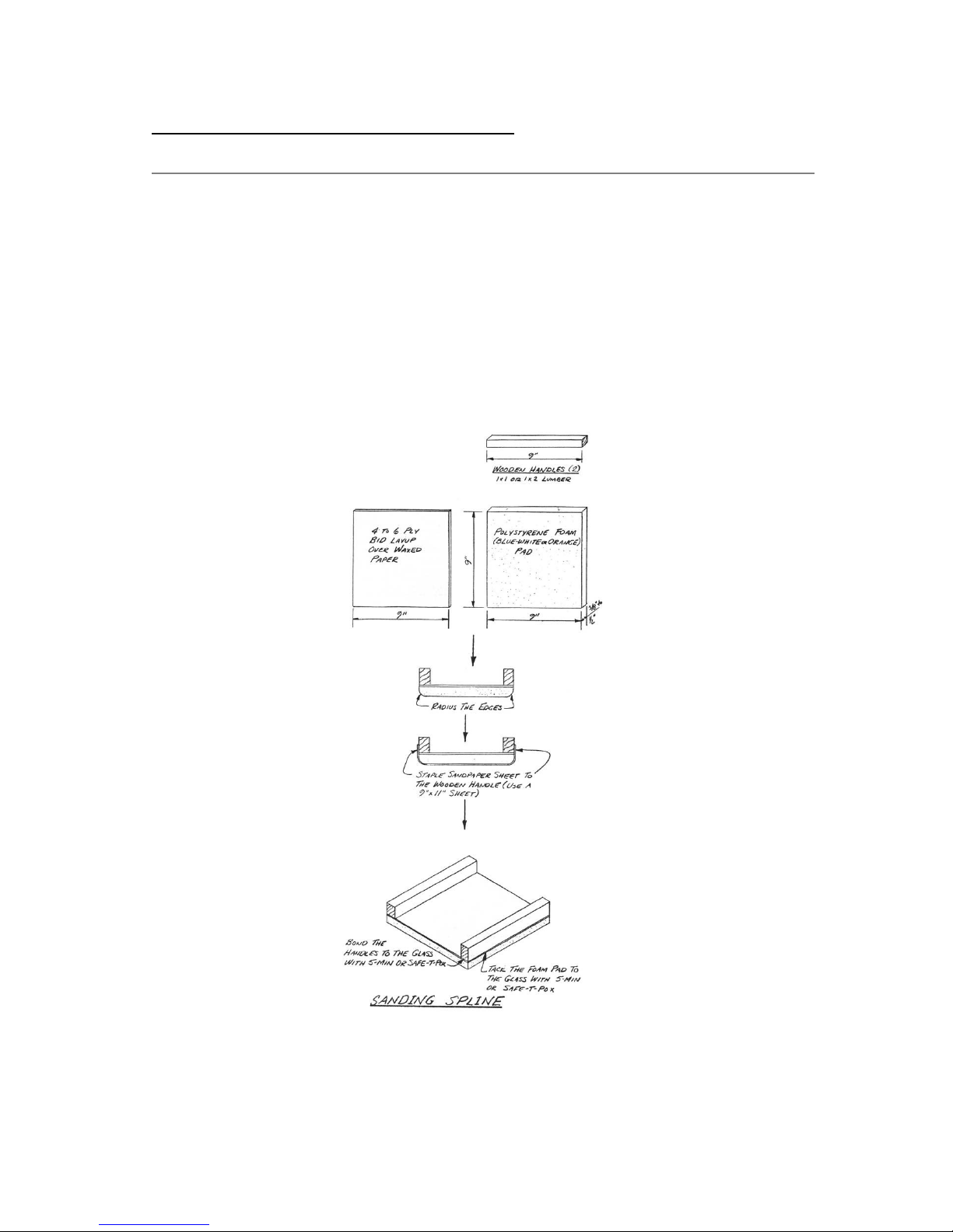
Q2 Plans - Chapter 3 - Page 3-15
.....The sanding spline is a finishing tool common to the sailplane
industry. It is an easy tool to make and does an excellent job of
contouring. You may find it handy to make two, one for coarse grit
sandpaper and one for medium or fine sanding. The spline is an easy
tool to use but it may require your close attention at first. The
spline is always held with handles parallel to the leading edge of an
airfoil surface (wing, canard, etc.) as shown in the sketch. The
sanding motion is on a diagonal to the leading edge while the
spline's handles are held parallel. This takes a little getting used
to but becomes second nature after a little practice.
Page 69
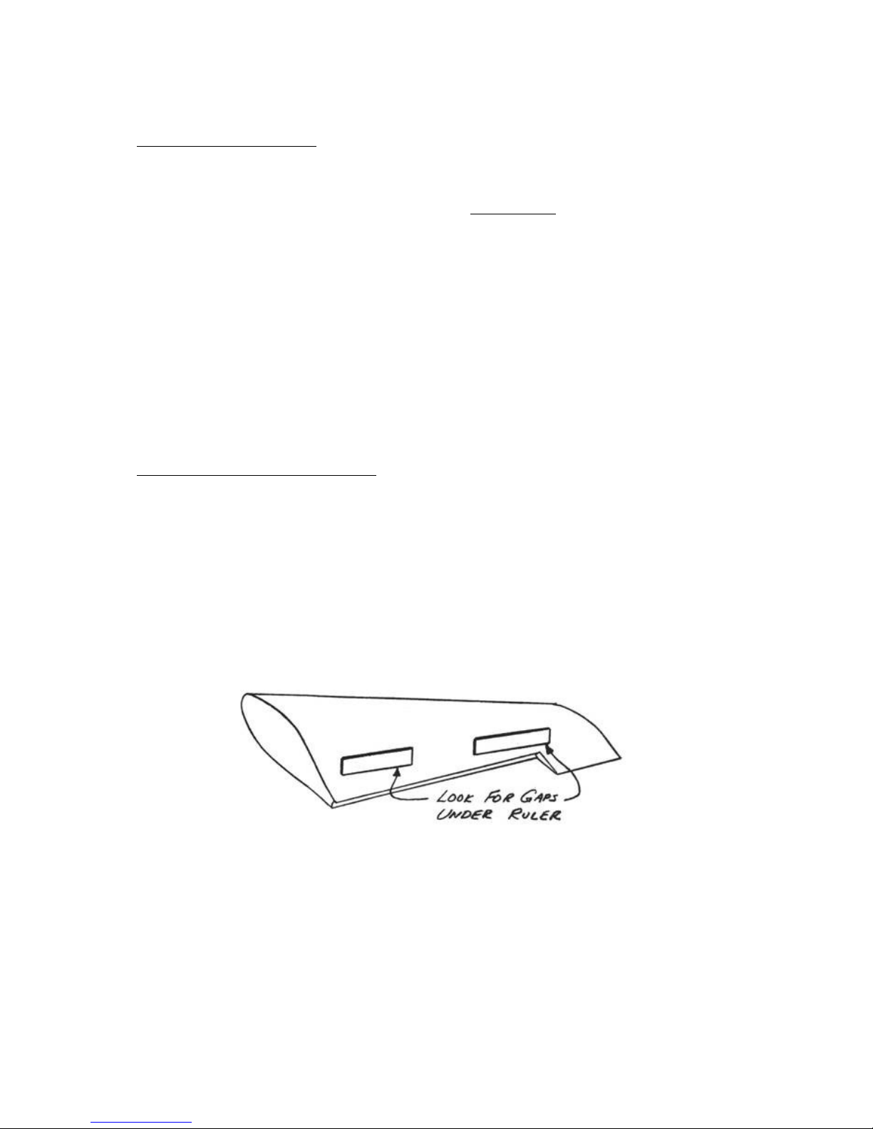
THE FINISHING PROCESS
..... Finishing the composite airplane is a five-step operation.
Repairs or rework of structure must be completed first, before the
obscuring finish is applied, and final structural inspections must be
complete. Second, coarse contour filling is done with
microspheres/mixed with epoxy (dry micro) as required in areas
requiring .03 inch to .20 inch of fill. Any exceptionally gross
filling (over .20 in) is also accomplished at this stage using a foam
filler. The initial contour sanding begins with the cured microsphere
filler, and exceptional caution must be exercised to avoid damaging
the structural skins while sanding. Third, featherfi1l is applied to
fill medium sized surface defects up to .03 inch, and as a general
fill of the glass surface weave. The fourth step is the application
of an ultra violet barrier primer. Fifth, the final finish paint is
applied.
.....The following sketches are descriptive of the finishing process
and its potential pit falls. The sketches use an exaggerated scale to
show details more clearly.
STEP ONE: INSPECTION/REPAIRS
..... Before you begin finishing, the entire structure must be
airworthy. You can hide poor workmanship from your own eyes and from
the inspector who will finally approve your first flight, but you
can't fool mother nature! All structure must be sound before finish
materials are applied. The following sketches are a review and
clarification of the quality control criteria found in Chapter 3 .
Each airplane must have a thorough inspection and required repairs
completed as the first step in finishing. The best way to inspect the
structure for bumps or dips is to place a 12" ruler on the wing or
canard span-wise, as shown. Gaps under it approaching 1/16" height
must be repaired.
Page 70
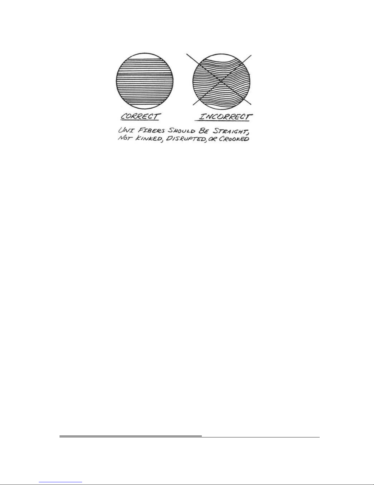
CONTINUED ON NEXT PAGE
PAGE 3-15
Q2 Plans - Chapter 3 - Page 3-16
Page 71
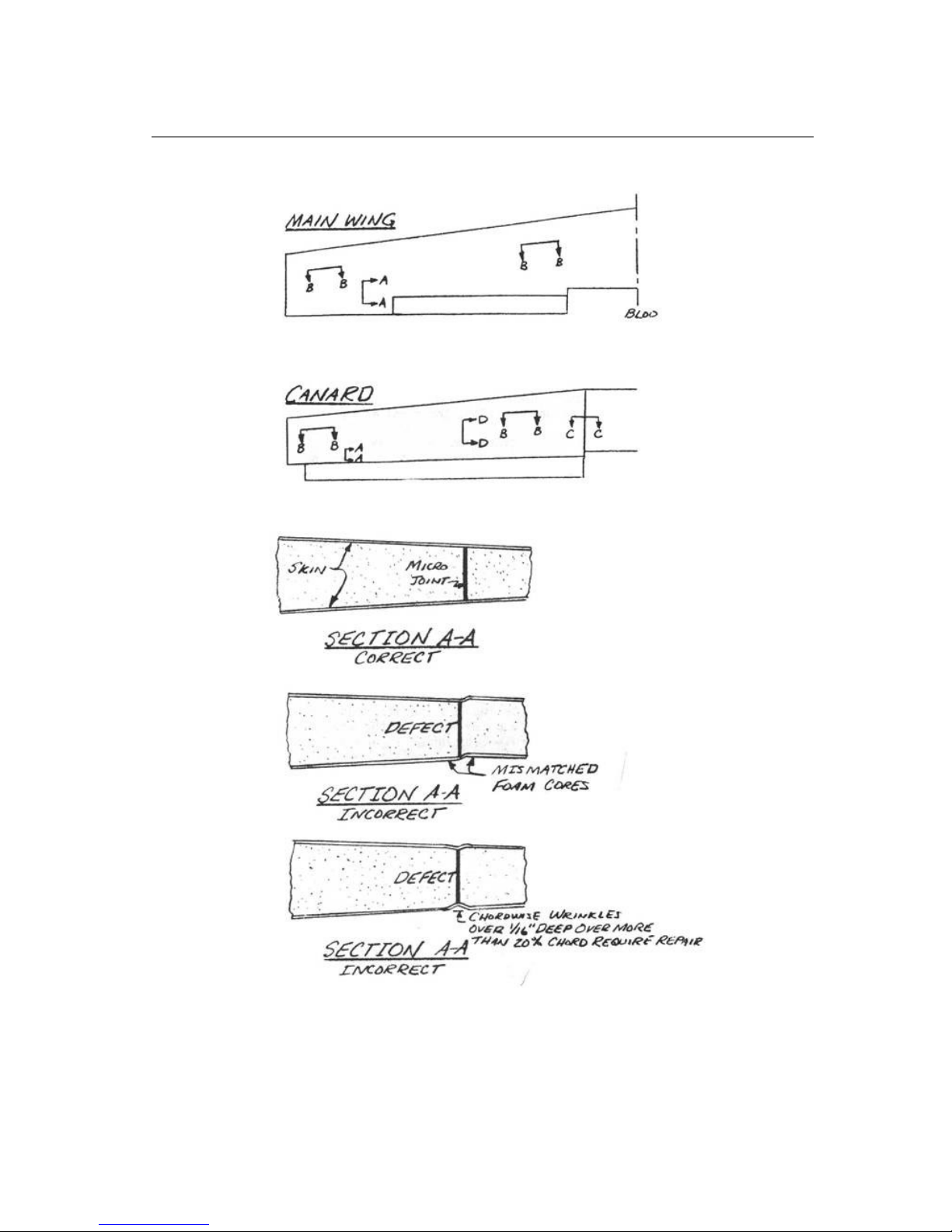
Page 72
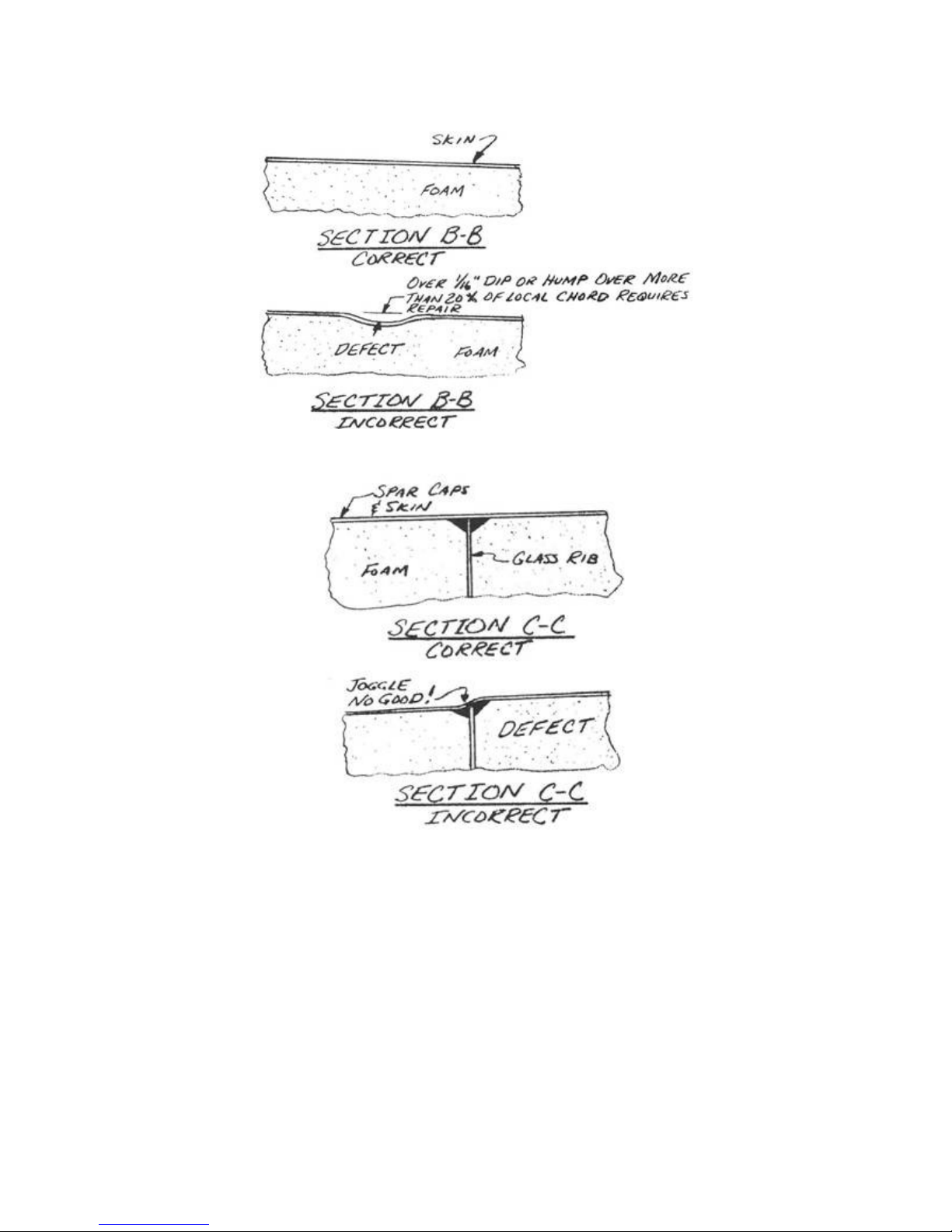
Page 73
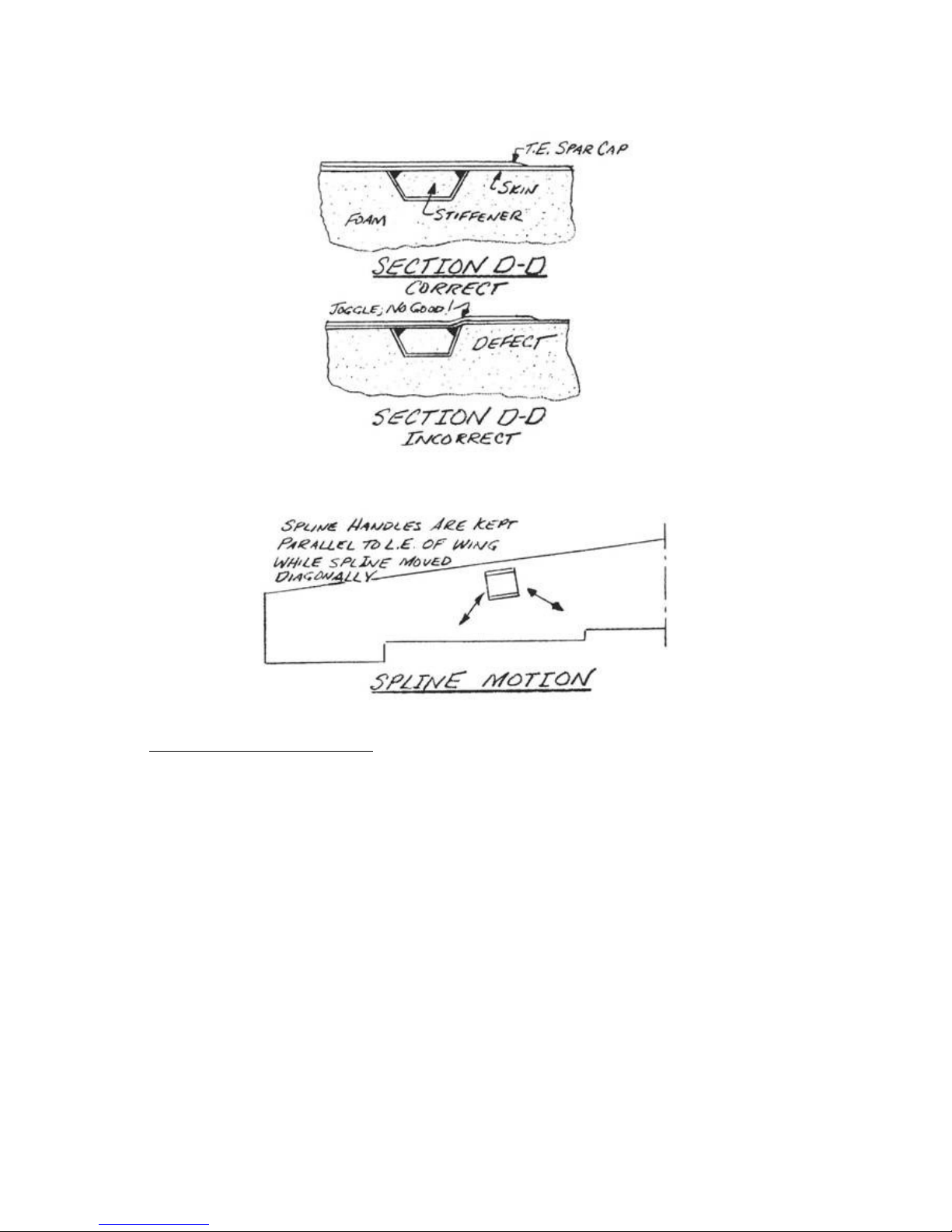
STEP TWO: COARSE FILLING
..... You must be extra cautious in this step or you may destroy your
structure. When you take a piece of sandpaper and start grinding on
your composite structure it's like using acid to clean a metal wing
spar. It must be done carefully! Start by determining which areas
require micro filler as shown using a flexible yard stick and a
scale. Prepare the areas to be filled by hand-sanding lightly. Do not
try to use a sanding block or spline on these areas.
Page 74
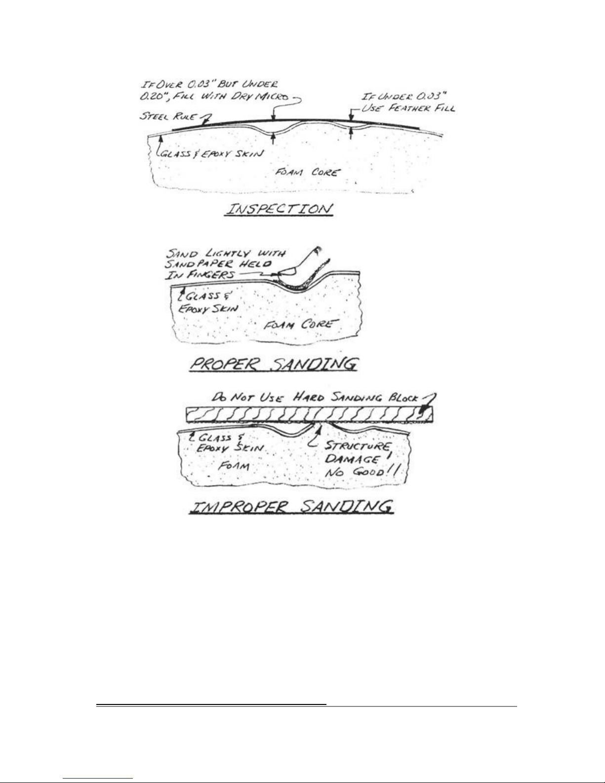
Q2 Plans - Chapter 3 - Page 3-17
CONTINUED ON NEXT PAGE
PAGE 3-16
Page 75
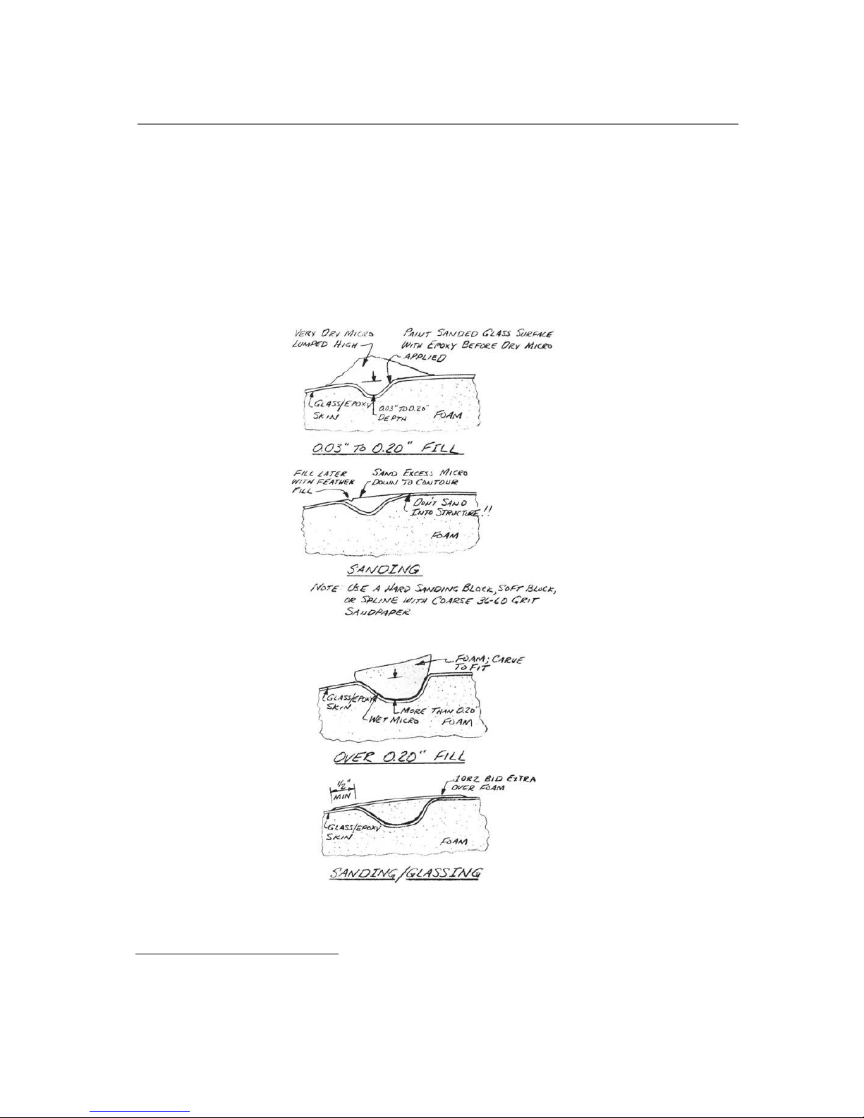
.....Paint a thin coat of epoxy over the area to be filled. Dry micro
is then lumped over the area. The fill must be high, such that
material is sanded away to bring the area into contour. The micro
should be mixed very dry (lots of microspheres) to save weight. Let
the micro cure at least 24 hours. Sand the micro overfill into
contour using a hard sanding block, or spline with coarse (36 to 60grit) sandpaper. Exercise extreme caution while sanding. A few
careless strokes with coarse paper can ruin your structure!
STEP THREE: FEATHER FILL
..... Sand the surfaces lightly by hand or with a soft foam sanding
Page 76
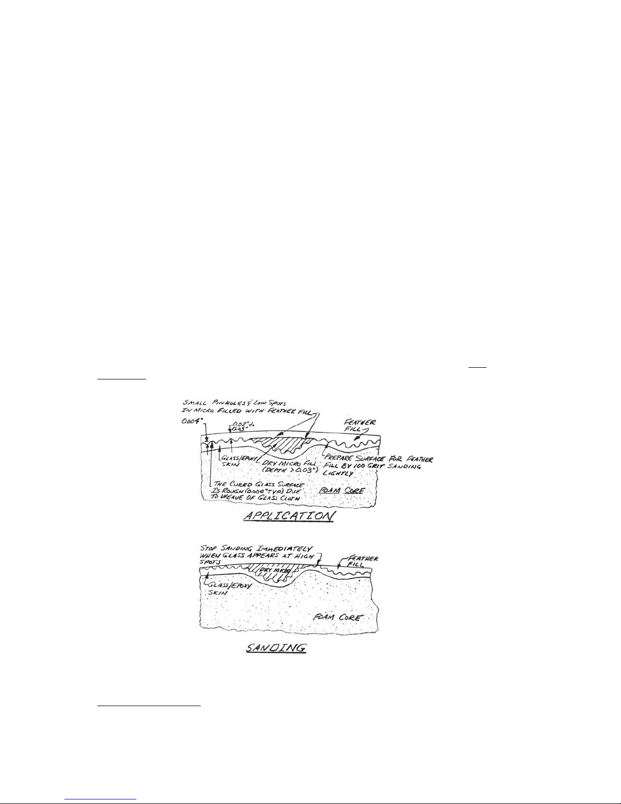
block in preparation for feather fill. A spray or brush coat of
feather fill will build up .02" to .03" thick, fill the glass weave
and any medium sized out-of-contour spots. Feather fill will require
several hours curing time before it can be sanded. The cured feather
fill is sanded to contour using a spline or soft block and 100-grit
sandpaper. Again, extreme caution must be exercised not to damage the
glass structure in pursuit of a good finish. The contouring must stop
immediately when the highest glass peaks begin to be visible as the
feather fill is sanded away.
.....If you find that you have underestimated the fill required or
just have a thin coat, don't hesitate to use a second coat of feather
fill. A well prepared surface generally won't need more than one
coat. When you have finished contouring the feather fill, the surface
should be basically smooth and fair. The primer to follow is not
intended to be contoured heavily, just smoothed with finer sandpaper
for a smooth finish while leaving a substantial ultra violet barrier.
.....After you have filled and contoured, re-inspect for sanding
damage; it is an easy thing to do! Remember, you are only allowed to
sand into the first skin ply in local areas no greater than 2 inches
in diameter and all of these areas must total less than 10% of the
surface area. Wherever there is only one ply, or where the UNI cloth
is crossed for strength (e.g. the canard and wing skins), no sanding
of the ply is allowed, except for "scuffing Up” the surface. Be
Careful!
STEP FOUR: PRIMER
Page 77

..... The ultra violet radiation barrier is provided by the heavy
carbon black content of the dried primer (Dupont 70S). The primer
gives the whole surface a flat black color and the sanding should
never remove it completely, exposing the light gray feather fill
below. The primer is sprayed on, allowed to dry, and sanded lightly
to achieve a smooth surface. The first primer coat is sanded using
220-grit and the second coat very lightly wet sanded with 320-grit.
When complete, the primer is very smooth, dark, and ready for finish
paint.
STEP FIVE: FINISH PAINT
.....Follow the manufacturer's directions for the type of finish
paint that you have chosen.
COCKPIT INTERIOR
.....It is not necessary to fill the glass weave, although some very
light sanding may be done to smooth the surfaces. Apply one coat of
the Dupont 70S primer to the interior glass, surfaces for ultra
violet protection prior to painting the interior.
.....A light color (light grey, green, or blue, etc.) is recommended
on the cockpit interior to avoid high heat buildup when the aircraft
is parked in the summer sun with the canopy locked. Automotive trunk
paint may also be used. Its “speckled" appearance will hide the weave
of the glass cloth.
PAGE 3-17
Q2 Plans - Chapter 3 - Page 3-18
Page 78
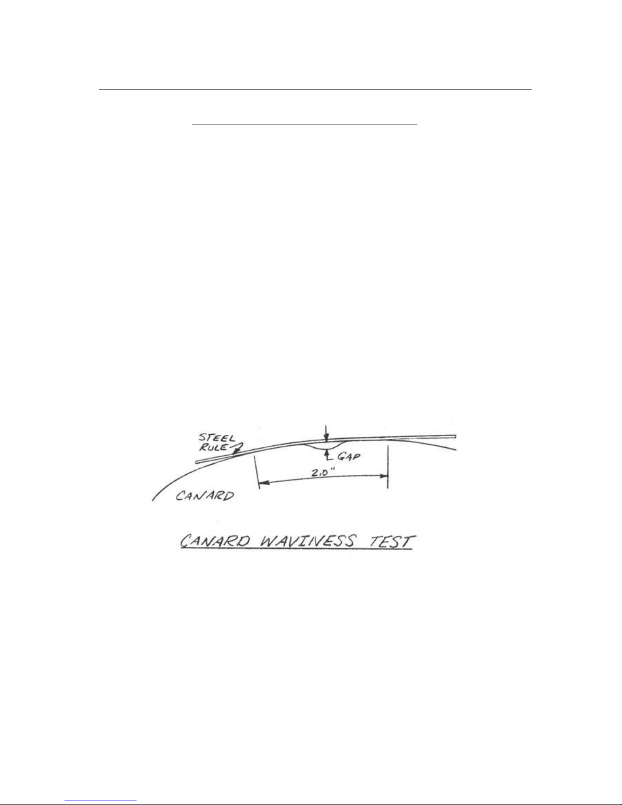
CANARD SURFACE SMOOTHNESS IS CRITICAL
.....During the Quickie program we built and installed a canard that
resulted in very poor low-speed performance. Stall speed was 10 mph
higher than predicted and tuft tests showed stall angle-of-attack
over three degrees lower than estimated. We later traced the problem
to a wavy upper surface; the canard must be smooth.
.....Of course, the big question is "how smooth"? The best way to
check this is with a steel pocket ruler, the flexible kind that's
only .0211 thick, or with a plastic drafting ruler. Hold the ruler as
shown in the sketch, pushing it to the surface with two fingers 2
inches apart. If the surface is a smooth curve between your two
fingers the ruler will lay down following the curve with no gaps. If
the surface is bumpy or wavy the ruler will touch the surface only in
3 or 4 places. Take a feeler gauge to measure the gaps between the
ruler and your surface. If you have a gap of more than .005 inch,
your surface is too wavy. Check this in several places from the
leading edge back to 50% chord. The bad Quickie wing had gaps of
about .012 inch. After refinishing with gaps of less than .005 inch,
its stall angle of attack increased from 8 deg. to 12 deg!
.....The best time to use the ruler and check for smooth surface is
when sanding the Featherfill with the spline. Recheck after sanding
the 70S black primer. It will not change when white paint is sprayed
on.
Page 79

AMATEUR-BUILT Q2 INSPECTION CRITERIA
1.0 SCOPE
..... This document has been prepared to assist inspection personnel
by providing recommended acceptance criteria and acceptable repair
practices for the Q2 amateur-built composite sandwich structure.
2.0 BACKGROUND INFORMATION
2.1 DESIGN CRITERIA
..... The materials, methods, and practices employed by the amateur
builder in the construction of the Q2 type are new to light aircraft
construction and may be unfamiliar to the inspection personnel
involved with the licensing of amateur built aircraft. Structural
design criteria for the Q2 exceed F.A.R. part 23 requirements. Inhouse component testing of the primary flight structure has been
conducted to 200% of design limits. Detail documentation of test data
is on file at Quickie Aircraft Corporation. The aircraft is
considered to be a utility category aircraft. Q2 builders are being
supplied with a complete owner's manual which specifies all placards,
operating limitations, normal and emergency operations, flying
qualities, maintenance specifications, inspection procedures, and
initial flight test procedures.
2.2 STRUCTURAL APPROACH
..... The basic structure throughout the design is a composite
sandwich of load bearing fiberglass skins separated by a light-weight
foam core. While the materials and processes are tailored to the
amateur builder, the structural layout is very similar to the
honeycomb composite structures stylized in military and transport
type aircraft and fiberglass sailplanes. Loads are carried by epoxy
jell-type fiberglass lamina. Foams of various types and densities are
employed as a form (upon which the load bearing material is shaped)
and as local buckling support. In no instance are foams used to
transmit primary loads, as is the case in some other amateur-built
designs.
2.3 INSPECTION TECHNIQUES
..... The transparent nature of the fiberglass/epoxy material allows
for visual inspection of primary structure from the outside prior to
finishing. Defects in the structure, as described in paragraph 3.0,
are readily visible even in the deepest laminate.
2.4 INSPECTION SEQUENCING
Page 80

..... The external visual inspection capability provided by the
materials allow inspection of all primary structures at any point
before finishing. All primary structures are at the surface,
eliminating the requirement for “pre-cover” or “closure” inspections.
Opaque filler materials are used throughout the airplane in
finishing, and inspection must take place before any areas are
obscured. Some areas may have opaque materials applied to one surface
where the structure is inspectible from the opposite side (wing
trailing edge for' example).
3.0 DEFECTS
3.1 VOIDS
..... Interlaminar voids in a new layup may be due to small air
bubbles trapped between plies during the layup. These void areas look
white and are distinctly visible even deep in a cured layup.
Interlaminary voids up to 1 inch in diameter do not require repair,
as long as they do not consist of more than 5% of the surface area.
Interlaminar voids (air bubbles) up to 2 inches in diameter are
acceptable when repaired as follows: A small hole is drilled into the
void and epoxy is injected into the void area. Small voids such as
this may occupy up to 5% of the laminate surface area.
Voids greater than 2 inches in diameter should be repaired as shown
in paragraph 4.
CONTINUED ON NEXT PAGE
PAGE 3-20
Q2 Plans - Chapter 3 - Page 3-19
Page 81

3.2 LEAN AREAS
..... Areas where the epoxy/glass matrix is incomplete because of
inadequate wetting of the cloth with epoxy (lean areas) are speckled
whitish in appearance. The fully wetted laminate will have a
consistent transparent greenish appearance. Epoxy lean areas are
acceptable, as long as the white speckled area is less than 10% of
the surface area. White to green ratios greater than 10% require
rejection or repair as shown in paragraph 4.
3.3 RICH AREAS.
..... Resin richness primarily adds weight to the laminate. While
some degradation of physical properties does occur, a overly wet
(rich) layup is not grounds for rejection.
3.4 INCLUSIONS
..... Bristle paint brushes are used throughout the layup process. As
a brush begins to deteriorate it will shed some bristles into the
laminate. The bristle inclusions, up to 20 bristles per square foot,
are not cause for rejection. Occasional inclusion of small wood chips
or other small foreign objects is not grounds for rejection.
3.5 FIBER DISRUPTION
..... In all instances, it is good practice to have the glass fibers
lying flat and without wrinkles. Major wrinkles or bumps along more
than 2 inches of chord are cause for rejection in the wings, canard,
and vertical fin, particularly on the upper surfaces (compression
side). Disruptions greater than 2 inches require repairs per
paragraph 4.
3.6 FINISHING DAMAGE
..... Damage to the external structure by sanding in preparation for
surface fill and paint can occur. Occasional sanding through the
weave of the first skin ply is not grounds for rejection. Sanding
through areas greater than 2 inches in diameter completely through
the first ply or any damage to interior plies must be repaired in
accordance with paragraph 4. A damp rag passed over the sanded
surface will make the plies show up to determine how many plies have
been sanded away.
3.7 SERVICE DAMAGE
..... Damage to the glass structure will be evidenced by cracked
paint, or "brooming" of glass fibers. Both of these indicators are
clearly visible. If either type of indication is present, the paint
and filler should be sanded away, bare laminate inspected, and
repairs made per paragraph 4 as required. Where surface damage has
occurred it is also likely that local foam crushing has been
inflicted.
3.8 DELAMINATIONS
.... Delamination of glass/epoxy lap joints is evidenced by physical
separation of plies. These defects are easily visible and easily
Page 82

repaired. The leading and trailing edges of flying surfaces (wing,
canard, vertical fin) should be free of delamination.
3.9 MULTIPLE DEFECTS
..... Where multiple types of small defects occur in a laminate
(voids, fiber dislocations, and lean areas for example), they should
not exceed a total of 10% of the surface area of the laminate, or 20%
of the wing chord at any one spanwise position.
4.0 REPAIRS
..... There are seldom single defects so massive that a major
component must be scrapped. The repair procedures described here may
be applied throughout the QUICKIE and Q2 composite sandwich
structures.
4.1 SMALL VOID REPAIRS
..... Voids up to 2 inches in diameter may be repaired by drilling a
small hole into the void and injecting the void full of epoxy. A vent
hole opposite the injection point is required to allow air to escape.
4.2 LARGE DEFECTS
..... Excessively large voids, lean areas, finishing damage, fiber
disruptions, major fiber wrinkles, or service damage may be repaired
using this procedure. Remove the rejected or damaged area by sanding
or grinding the taper the glass laminate on a slope of approximately
1 inch per ply in all directions. The plies are visible as the
sanding is done. The tapered glass edges and surrounding two inches
of glass surface must be sanded completely dull. Damaged underlying
foam should be removed and the void filled with a dry
microsphere/epoxy mixture or a replacement foam piece. The damaged
area is then laminated over using the same type and orientation of
glass plies removed, each ply lapping onto the undamaged glass at
least one inch. The whole repair area is covered with an additional
bi-directional glass ply.
4.3 DELAMINATIONS
..... A delaminated joint should be spread_ the mating surfaces
sanded dull, gap filled with flox (epoxy/flocked cotton mixture)_
then clamped shut while it cures.
5.0 MATERIALS
..... Since a wide range of similar appearing materials exists which
exhibit substantial differences in physical (structural) properties,
Quickie Aircraft Corporation has established a distribution system to
provide the amateur builder with proven acceptable materials. Quickie
Aircraft Corporation strongly discourages the substitution of
materials. Homebuilder substitutions for the basic structural
materials constitutes major structural modification to the Q2 design,
and could adversely effect flight safety.
6.0 APPLICABILITY
..... These acceptance criteria are different from and, in some
cases, much looser than for similar structures found in sailplanes
and other contemporary composite structures. These criteria apply
Page 83

only to the QUICKIE and Q2 structures. Design safety factors in
excess of three enable somewhat relaxed acceptability criteria
compared to other similar structures.
PAGE 3-20
Q2 Plans - Chapter 3 - Page 3-20
Page 84
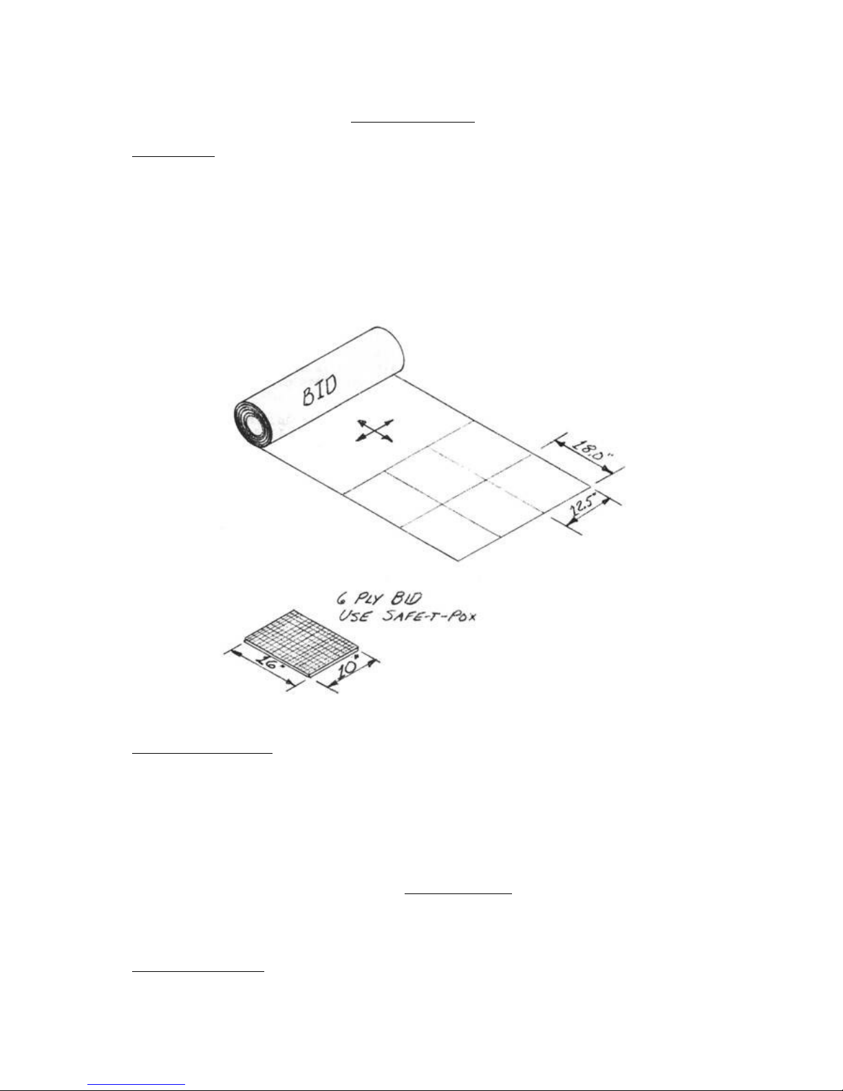
PRACTICE LAYUPS
FLAT LAYUP
.....The first practice layup that you will make is a layup of six
BID plies onto a flat surface. This is intended to give you
experience in the techniques of glass/epoxy work and to give you a
check on your workmanship. You should be able to complete this layup
in about half an hour. Protect your work bench by taping waxed paper
over an area about 24" by 24", (or, find a piece of metal and wax its
surface). This will keep the epoxy from bonding to the table top. Cut
six plies of BID that are about 12 1/2 inches by 18 inches.
.....Laminate the six plies on top of the waxed paper. Try to do your
best job of stippling and squeegeeing so that the plies are
completely wetted but not full of excess epoxy. Let the layup cure to
knife trim, about four hours. Carefully mark a 10 inch by 16 inch
rectangle and knife trim the layup to that size using a sharp razor
blade or trim knife. Allow the layup to cure completely. If you
forget the knife trim, cut the cured piece with a coping saw or band
saw.
.....Take the cured 10"x16" piece to your post office, or any
accurate scale, and ask them to weigh it for you. Your laminate
should weigh between lO 1/2 and 12 1/2 ounces. A 10 1/2 ounce layup
is about as light as can be done without voids (white areas). A 12
1/2 ounce layup has too much resin, and if you make all of the 1ayups
in the airplane this wet, your Q2 may be as much as 50 pounds over
weight. An 11 ounce layup is just about perfect. Save this piece; it
will be useful to check future 1ayups against.
CONFIDENCE LAYUP
Page 85
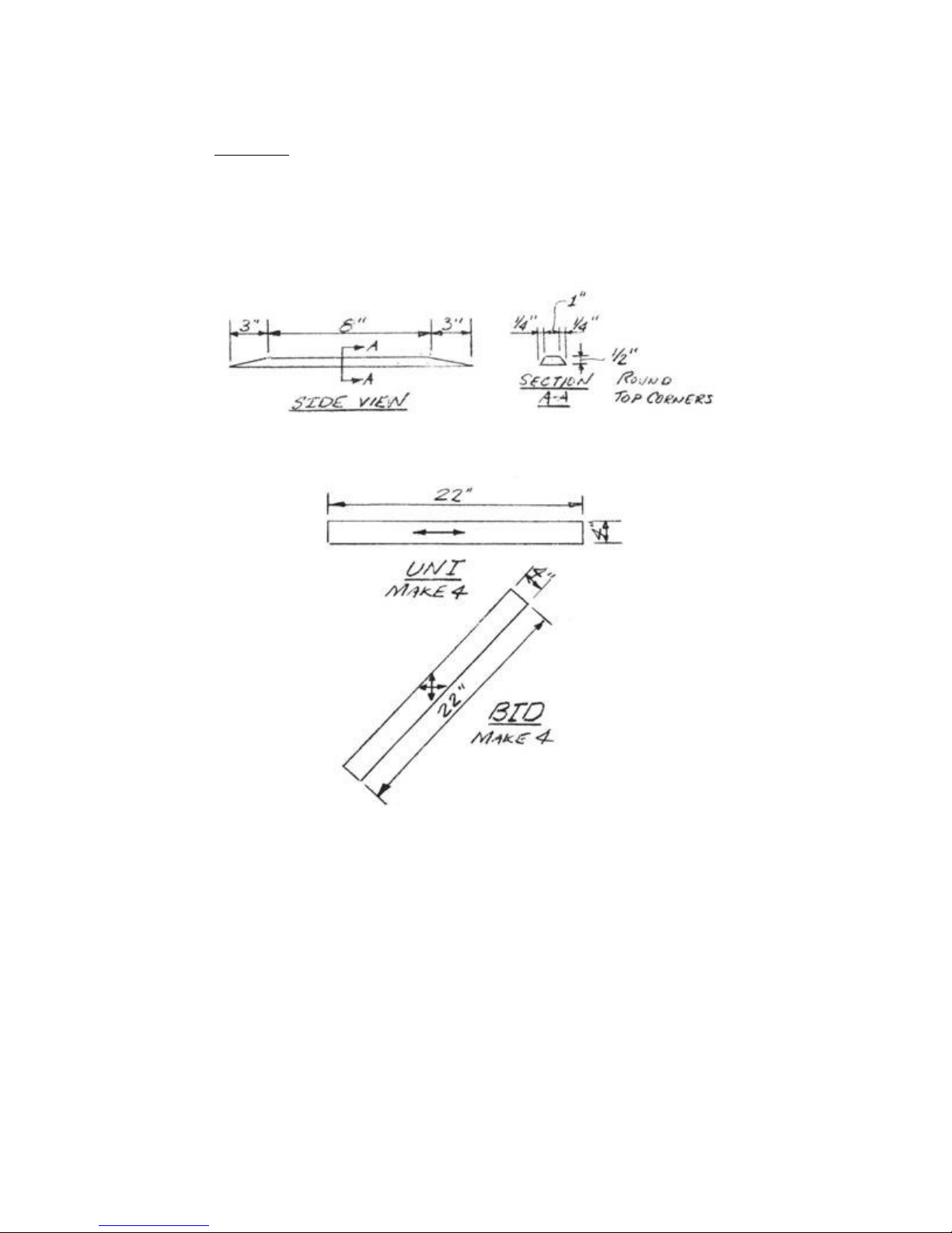
.....The second practice layup is one intended to give you confidence
in the strength of your work. This layup is a sample of composite
sandwich structure and is typical of the load carrying structures in
your Q2. When this layup is finished, and completely cured, you will
subject it to a simple load test, and thus demonstrate the strength
of your workmanship.
.....First, tape a piece of waxed paper about 30 inches long to the
top of your work table. Shape a piece of green foam as shown.
.....Go to your glass cutting area and cut the glass plies shown.
.....Lay up two plies of UNI, two plies of BID, paint the foam with
micro slurry, and press it in the center. Then lay up the other BID
and UNI plies. Be careful to work a11.air bubbles out of the corners.
The best way is to stipple with the brush. The glass is oversized so
that it can be trimmed to exact dimensions later. Trim to the
dimensions shown after curing 24 hours, using a coping saw or band
saw. Allow the piece to cure for four days at room temperature before
the load test.
Page 86
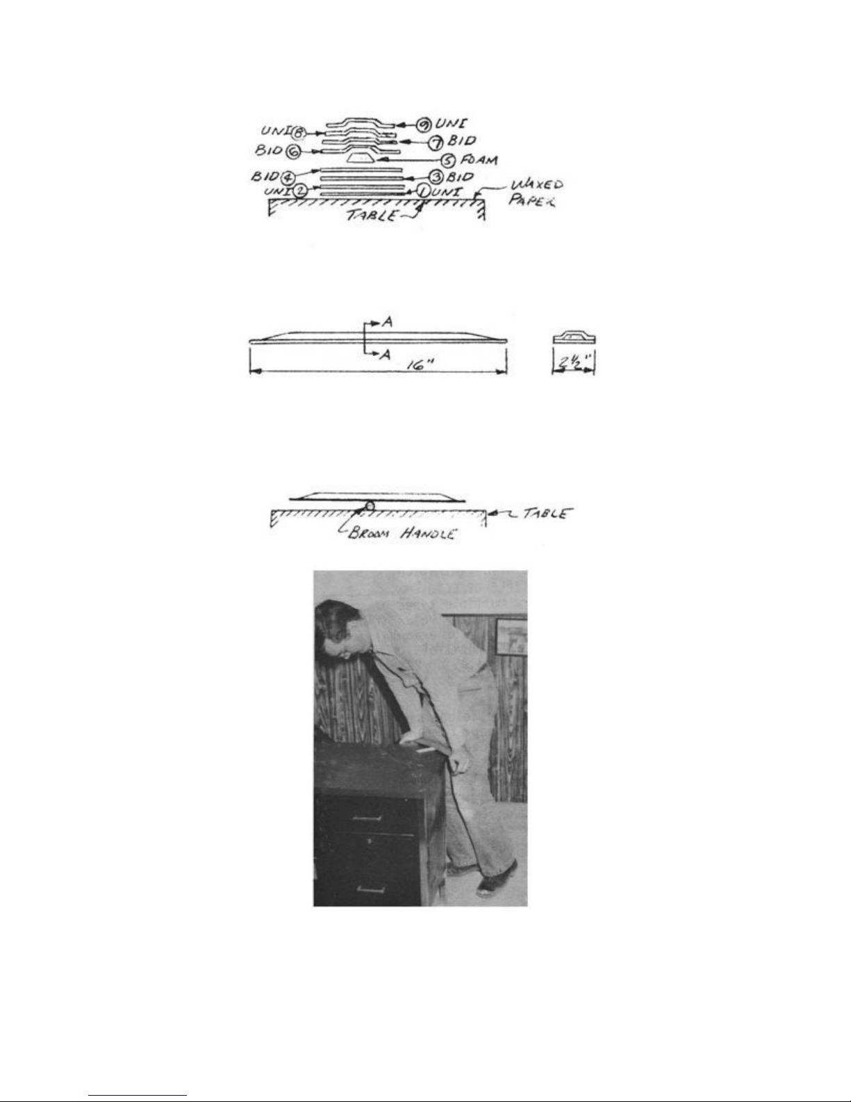
.....Now for the test: lay a broom handle or piece of tubing on the
work bench and try to break the sample by putting all of your weight
on the ends. A 200 pounder will stress the sample more than any part
of your airplane is stressed at 10 g's.
PAGE 3-20
Page 87
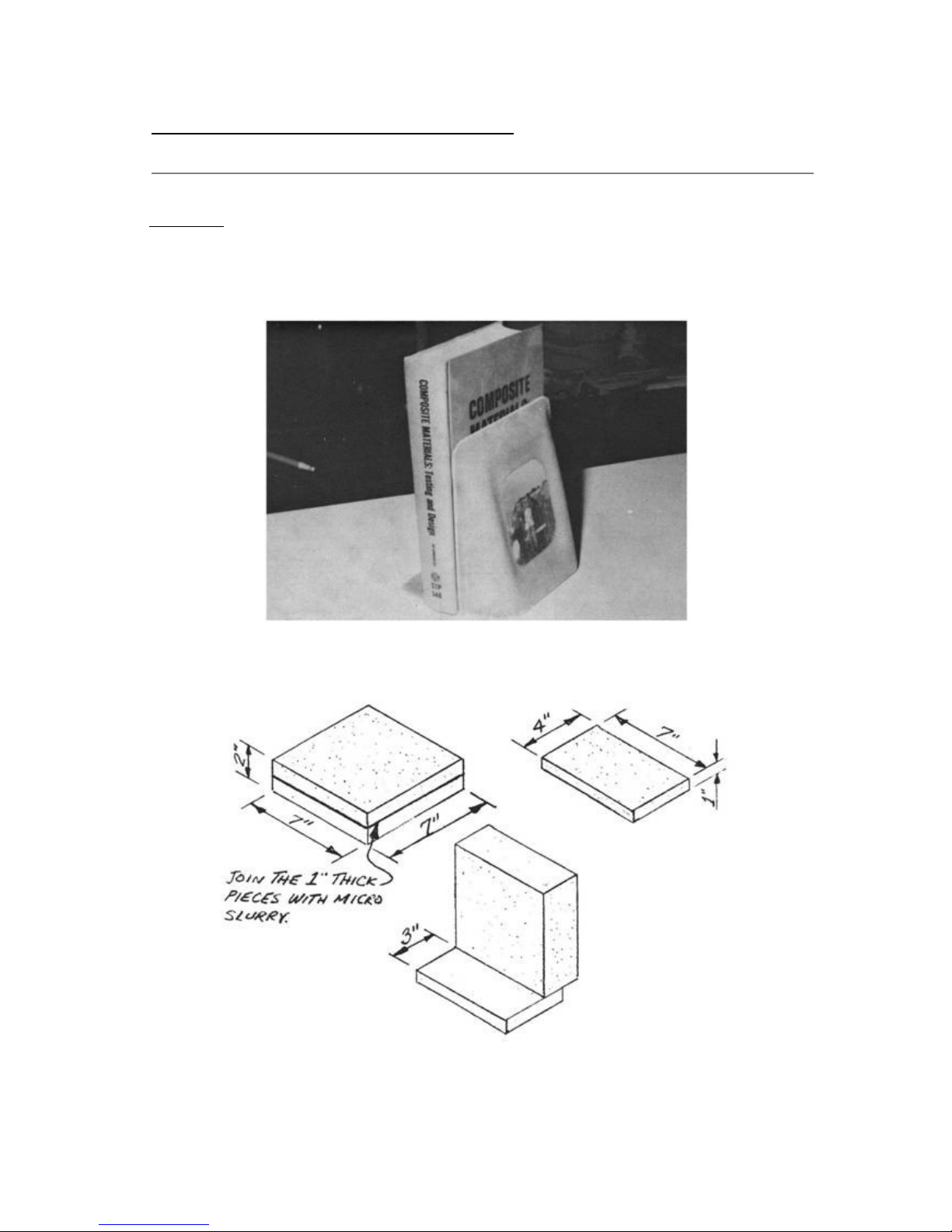
Q2 Plans - Chapter 3 - Page 3-21
BOOK END
.....The last practice part that you will make before starting on your
airplane is a book end. It takes three layups to make the book end and
involves most of the operations that you will need to learn, to build
your airplane.
.....Cut the 3 blocks of green urethane foam (2lb/ft3) as shown.
Nail them together.
.....Cut three plies of BID as shown.
Page 88
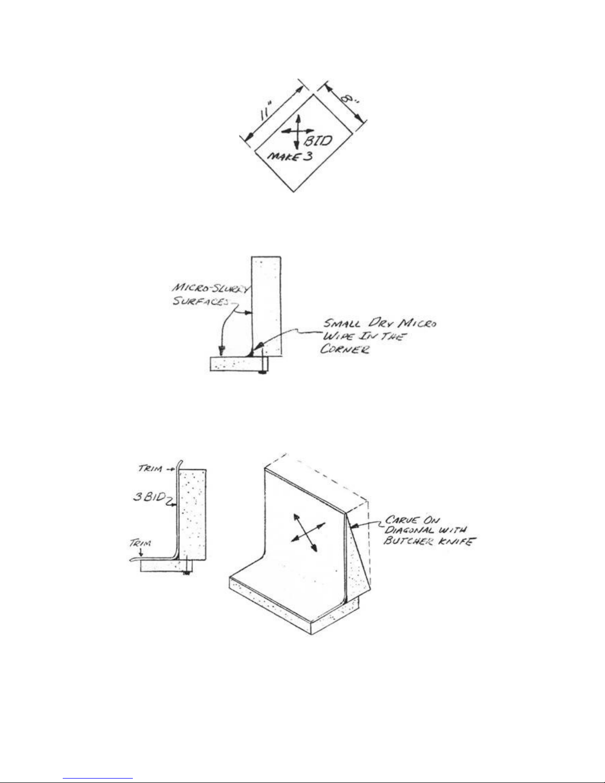
.....Mix 4 oz. of Safe-T-Pox epoxy; using about 1 oz, make a small
batch of micro slurry and coat the foam as shown. Make dry micro from
the leftover slurry and a small radius with it as shown.
.....Lay up the first ply of BID as shown.
.....Using plain epoxy (no micro), lay up the other two plies and
allow to cure. Note how the 45° fiber orientation allows the glass to
lay down completely into the small radius.
.....Knife trim along the foam edges. After the first layup has cured
and the edges have been trimmed, the thicker foam block is carved and
contoured as shown.
Page 89
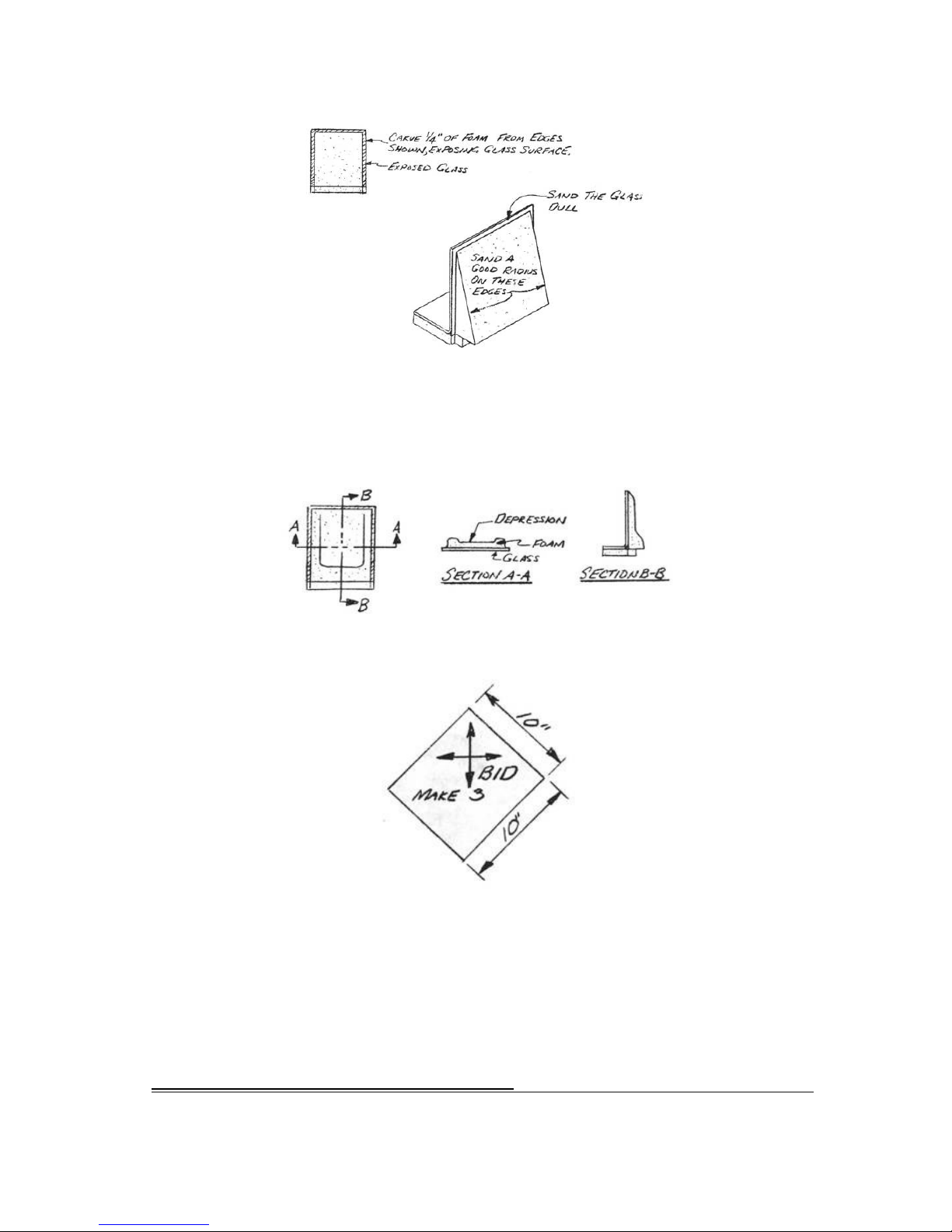
.....Put a generous radius on the foam edges and sand the wide glass
edges dull for glass to glass bond. Use your wire brush to rough out a
depression in the middle of the block. Finish smoothing the depression
by rubbing it with a scrap of green foam. Radius the corners of the
depression. Blow or brush all of the foam dust off the surfaces.
.....Cut three plies of BID as shown.
Q2 Plans - Chapter 3 - Page 3-22
CONTINUED ON NEXT PAGE
PAGE 3-21
Page 90
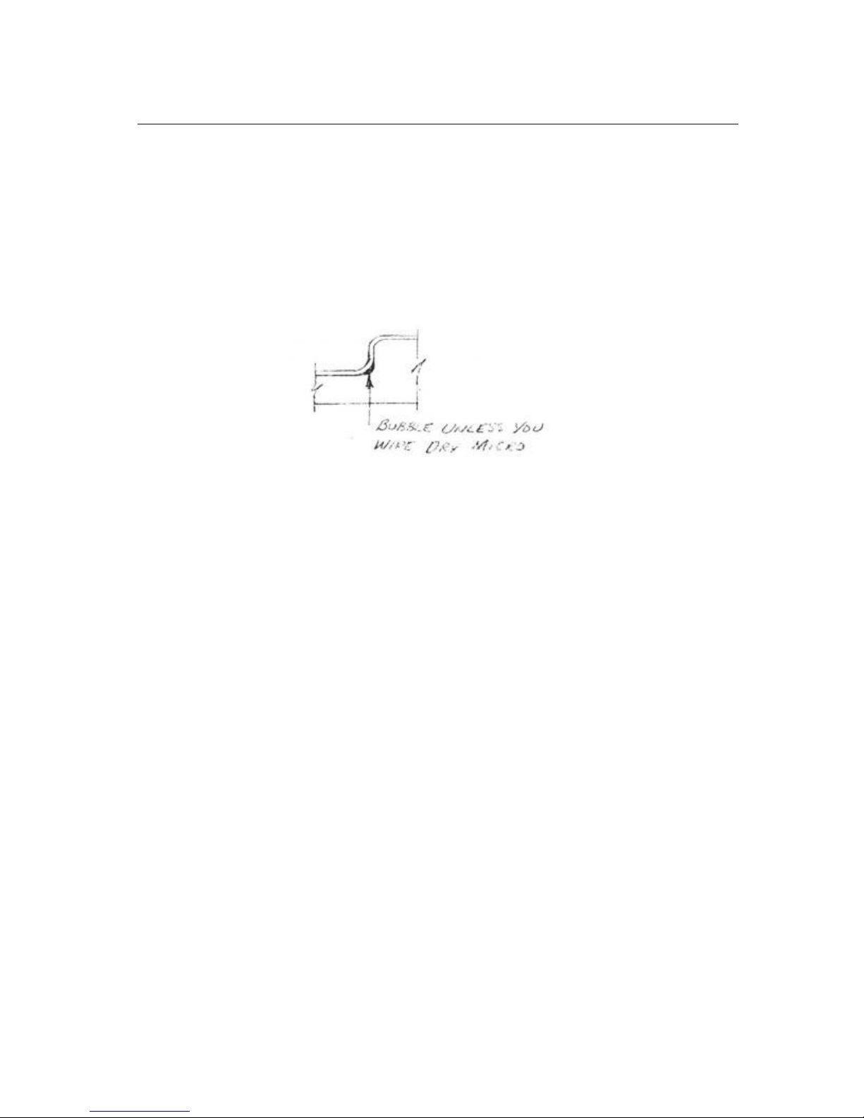
.....Mix Safe-T-Pox, make a small batch of slurry, and save the
remaining epoxy. Slurry the foam surface and apply two plies of BID
to the contoured surface. Start the layup in the center and work out
toward the edges. If you have trouble getting the glass into the
depression corners without bubbles, lift the plies and wipe in a
little dry micro. You will then find that it will lay smoothly in
without voids (see sketch). This depression is sharper than any in
your airplane and is intended to give you a feeling of how sharply
you can form the cloth.
.....Before laying the third BID ply down, place your favorite photo
in the depression, and then lay the third BID ply over it. Scissor
trim the excess glass cloth. Allow to cure and knife trim the edges.
The lower edge is trimmed flush with the bottom of the foam block.
Page 91
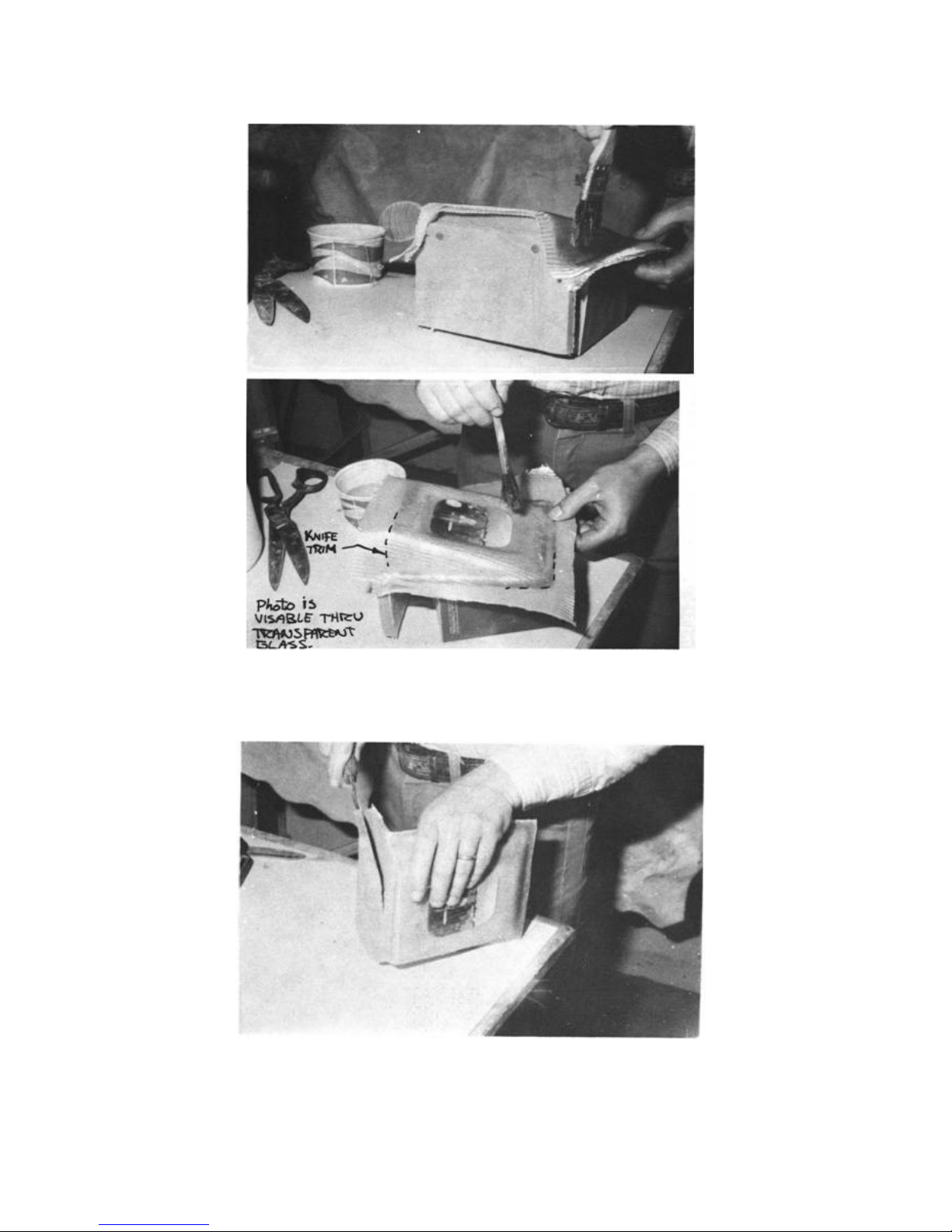
.....Wait until the second layup is fully cured. Remove the 1 inch
foam block with a butcher knife and sanding block. Remove foam for a
1/4" flox corner and sand the glass surface dull.
Page 92
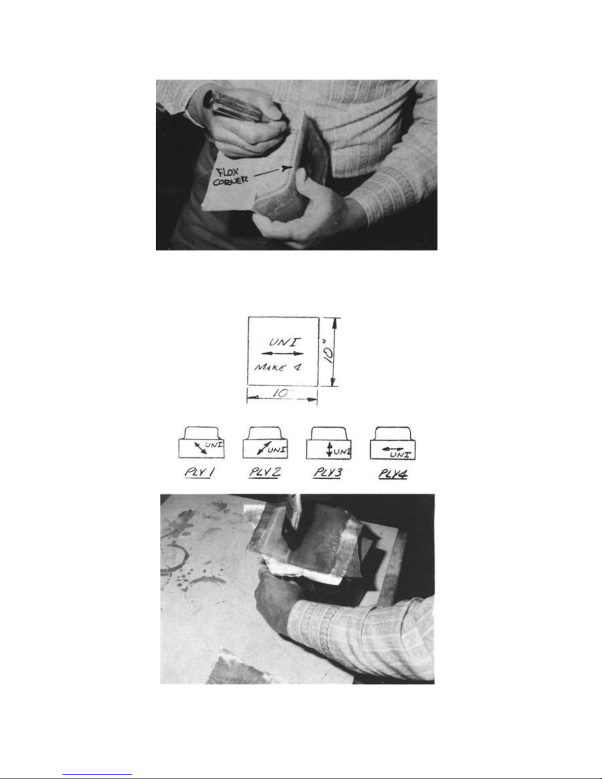
.....Mix Safe-T-Pox, a small batch of flox, and a small batch of
micro slurry. Fill the corner with flox and slurry the foam. Lay up
the four UNI plies with the orientation shown.
Page 93
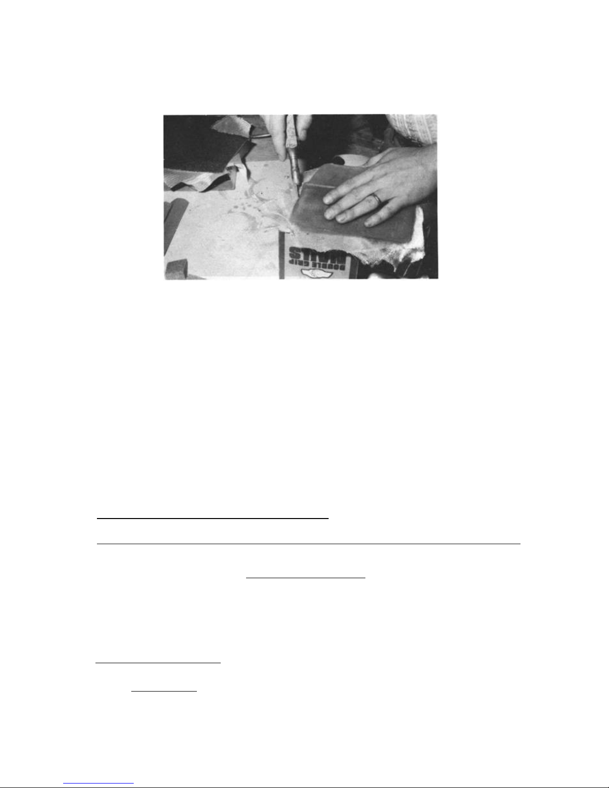
.....Knife trim the edges. After 12-hour cure, sand the edges with
100-grit sandpaper as required for smoothness and good appearance.
.....It may at this time seem a bit ridiculous to use three layups,
about four hours work, and two days cure, just to make a book end!
But remember, this book end was not designed for ease of
construction; it was designed instead, to let you get a first hand
exposure to the following operations before starting on your
airplane; glass cutting, foam preparation (slurry), BID and UNI
layups, flat surfaces, corners, and compound curves, flox corner,
knife trim, concave and convex foam carving, glass to glass surface
preparation, and sanding edges. So, use this experience to your best
benefit and spend the curing time studying the plans. Even if you're
experienced in glass layups, the book end is a worthwhile project to
get familiar with the workability of this BID and UNI weave cloth
PAGE 3-22
Q2 Plans - Chapter 3 - Page 3-23
EDUCATION SUPPLEMENT
Rip this page out of your plans and staple it to the wall of your
shop. While it is a handy reference, it's still a good idea to read
all the words in the education chapter once in awhile. Don't skip the
details - they're all important.
BASIC LAYUP PROCEDURE
1. PREPARATION : Ply 9 or gloves on hands, shop temperature 75° +
10°.
Page 94
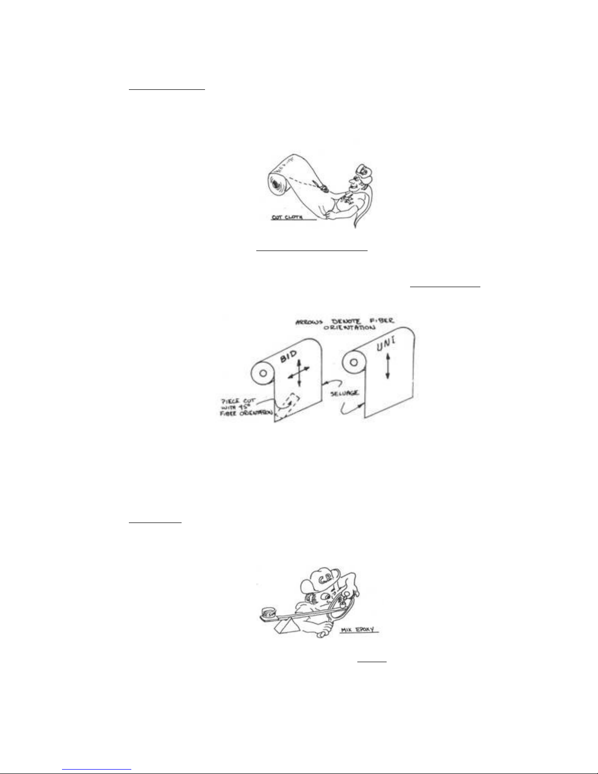
2. CLOTH CUTTING : You-can get by with just a standard pair of good
fabric scissors, but the job is much easier with the large pair
of industrial scissors (Weiss model 20W). They're $25 (gulp!)
but worth it in the long run.
SURFACE PREPARATION:
FOAM - Hot-wire-cut surface needs no preparation. Sand ledges or
bumps even, fill holes or gouges with dry micro immediately
before the layup. Brush or blow away dust.
GLASS - Always sand completely dull any cured glass surface (36grit or 60-grit sandpaper). Re-sand if it has been touched with
greasy fingers.
METAL - Dull with 220-grit sandpaper.
3. MIX EPOXY : Follow all mixing steps shown on your epoxy balance.
Mix two minutes, 80% stirring and 20% scraping the sides and
bottom. Don't mix with a brush.
Micro Slurry - Approx equal volumes of mixed epoxy and
microspheres.
Page 95
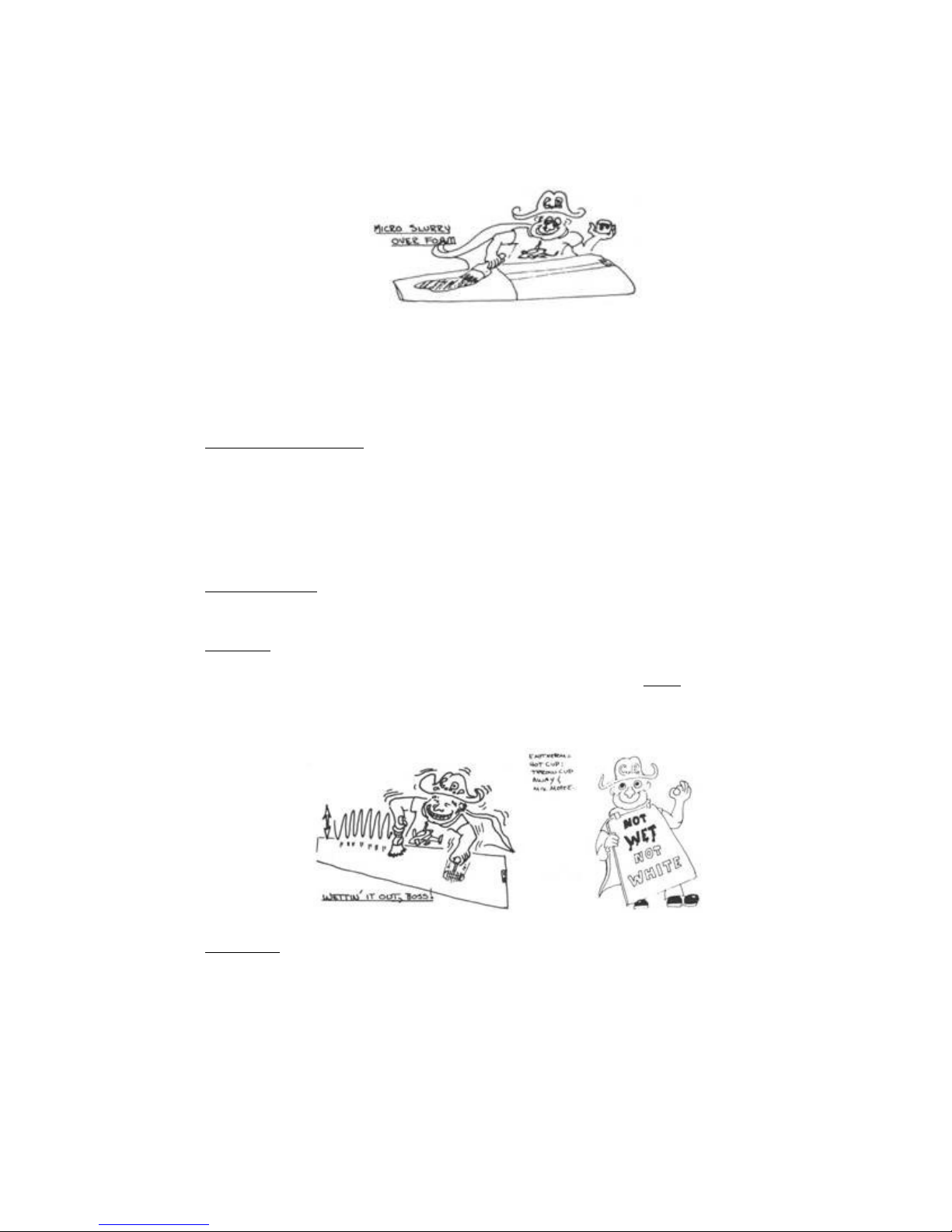
Wet Micro - Enough microspheres for a "thick honey" mix.
Dry Micro - Enough Micro so it won't run.
Wet Flox - Thick, but pourable mixture of epoxy and flocked
cotton.
APPLY TO SURFACE:
Layup Over Foam - Brush or squeegee on a thin micro slurry layer
(thick over urethane).
Layup Over Glass - Brush on a coat of epoxy.
4. LAY ON CLOTH : Pull edges to straighten wrinkles. If working
alone on a long piece, roll the cloth then unroll it onto the
surface.
5. WET OUT : Don't slop on excess resin; bring epoxy up from below
with a vertical "stab" of the brush ("stippling") or a squeegee
action. Start in center and work out to sides. Most of the time
of a layup is spent squeeging. Stipple resin up from below or if
required, down from above. "NOT WET, NOT WHITE."
6. SQUEEGEE : If you have excess resin, squeegee it off to the side.
Use squeegee with many light passes to move epoxy from wet areas
to dry areas.
Page 96
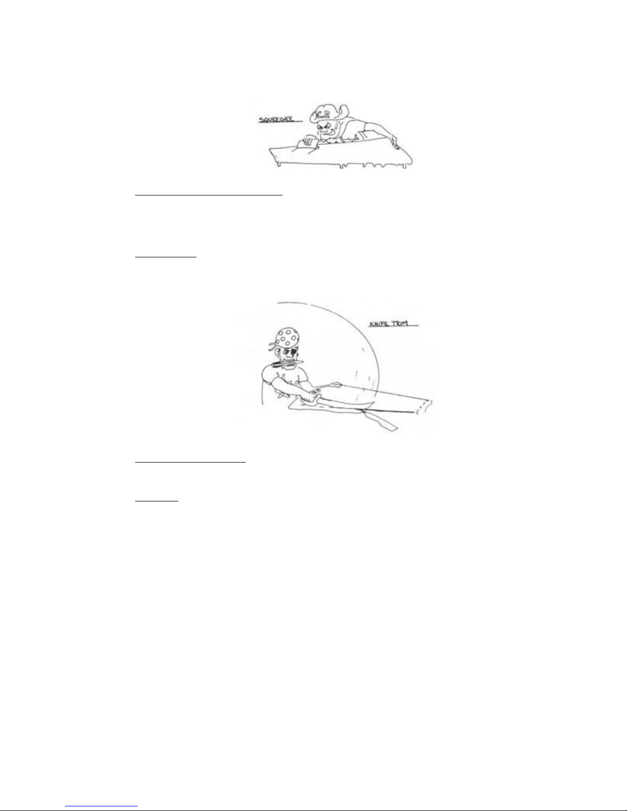
7. PRELIMINARY CONTOUR FILL : Save sanding by troweling dry micro
over low areas while the glass layup is still tacky. This is
done at trailing edges, spar caps, or 'over any low areas. The
low places are overfilled with micro then sanded smooth after
full cure.
8. KNIFE TRIM : Save work of sawing and sanding edges by razor
trimming the edges at the "knife trim stage," which is about 3-4
hours after the layup.
9. GENERAL INSPECTION : Take a good look for dry glass, excess
resin, bubbles, and delamination before walking away from your
wet layup.
10.CLEANUP : If you've used Ply 9 skin barrier, you can get all
epoxy off your hands with soap and water. Epocleanse is also
excellent for removing epoxy and it returns natural skin oils.
Brushes - rinse twice in MEK and wash with soap and water.
Throwaway after two to four uses.
Page 97
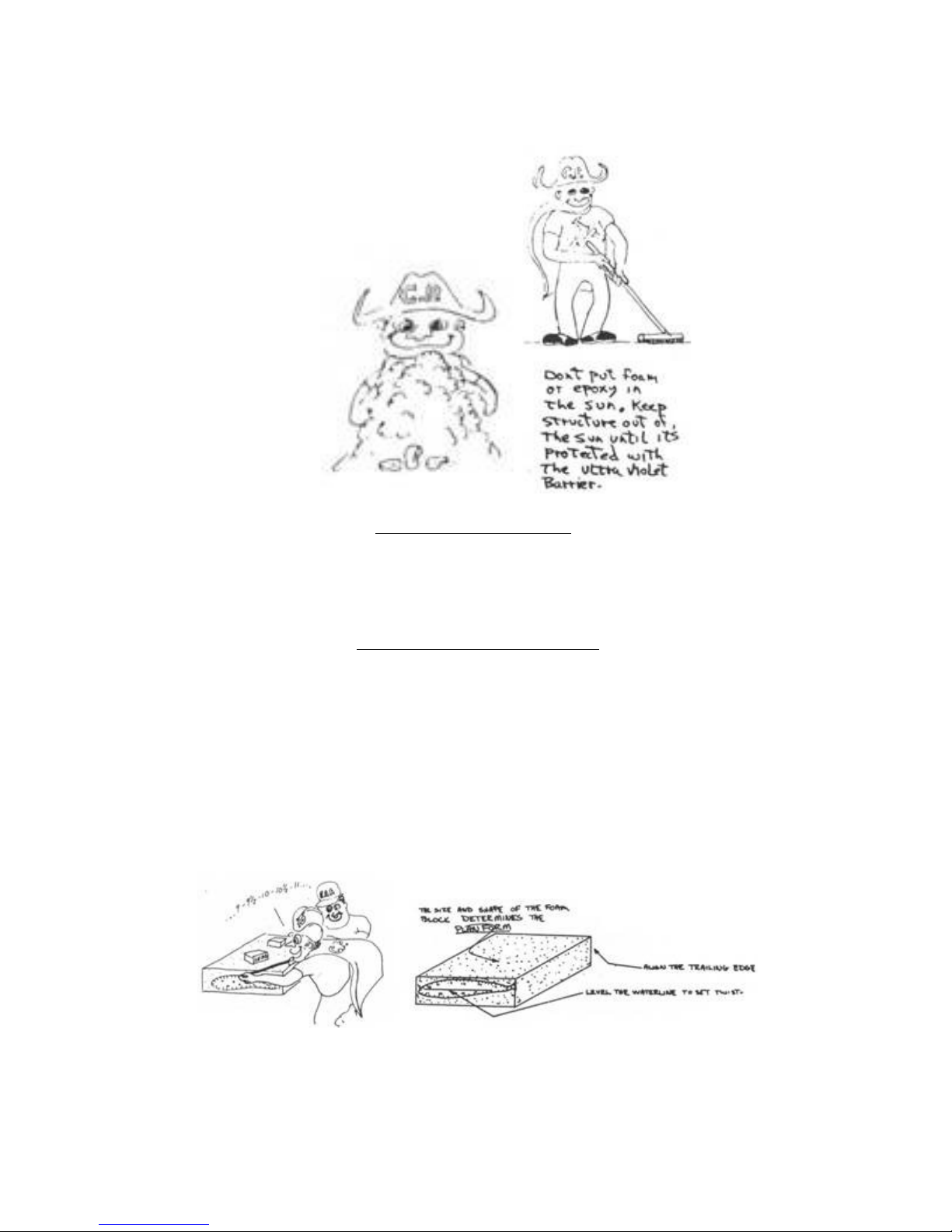
URETHANE FOAM SHAPING
.....BASIC TOOLS: Sharp butcher knife, sanding block, surfoam file,
wire brush and blocks/scraps of urethane. Use a dust mask. Hack away,
have fun.
HOT WIRE CUTTING STYROFOAM
.....Hot wire tool has a length of 56".
.....Wire must be tight. The adjustable voltage control is best, but
the job can be done with 212-volt, 6-amp battery chargers or 12-volt
car batteries. Foam block must be well supported and weighted.
Templates must be nailed on tight. First cut the basic block to size;
this determines the planform size and shape. Level the template level
lines; this determines correct twist. Set hot wire temperature for
about 1" travel through the foam in about 4 to 6 seconds with light
pressure. Do the actual cutting at about 1" every 6-7 seconds (8-10
sec. around the leading edge). Practice on scraps first.
Page 98
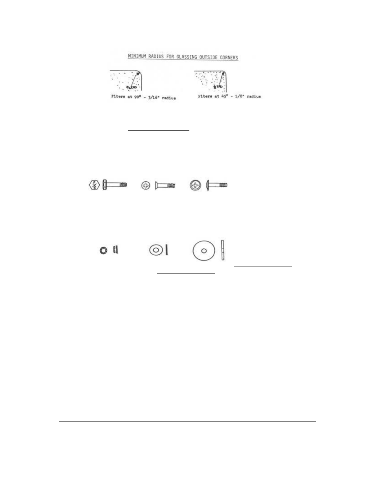
HARDWARE SKETCHES
AN3 3/16"
dia. bolt
AN4 1/4"
dia. bolt
all metal
lock nut
AN363-1032
AN363-428
AN509
flush head
screw
plain
washer
AN960
AN525
washer head
screw
wide washer
AN970
CRITERIA/REPAIRS
See the Education section
END OF CHAPTER Page 3-23
QUALITY CONTROL
Page 99

Q2 Plans - Chapter 4 - Page 4-01
INDIVIDUAL PART CONSTRUCTION
INTRODUCTION
..... The first task in the construction of your Q2 is to make many
of the small, individual parts required for assembly later. Quickie
Aircraft Corporation has found that making these parts at one time is
most efficient and will also give the builder a chance to gain
experience working with his hands on small pieces that can be easily
remade.
.....The parts include templates that are used for jigging and
rigging various portions of your aircraft. Drawings are provided
within this chapter, but primarily the templates are provided in a
series of large Appendix drawings included with these plans. All
templates are printed full size.
.....Jigging and rigging templates should be constructed from
material such as hardboard, plywood, or masonite of 1/4" thickness.
Aircraft quality materials are not required. The hot-wiring templates
for the main wing, canard, and vertical fin, as well as the control
surfaces, should be made out of thin aluminum, masonite, or aircraft
quality plywood. These templates must be smooth and wave free, so
spend considerable time on each one and sight frequently along the
line to check for waves or notches. Any wave or notch will be
reflected directly in the shape of your wing, etc. and will be
difficult and heavy to correct later on; so do a good job in the
beginning.
.....Template drawings provided for parts made as a sandwich
composite (glass-foam-glass) should still be made on the hardboard,
plywood, or masonite of 1/4" thickness. It will be much easier to
transfer the complicated curves and lines to the actual part if you
have a material more durable than heavy paper.
.....The phonolic bearing block comes delivered to you with all of
the important precision holes already drilled and reamed to the
proper size. The remaining holes are for bonding strength and are
non-critical on a precise diameter and position.
.....Be sure to identify and number each template and part so that it
can be identified easily later when it is needed. Further, group all
parts of the same family (e.g. Control System (CS), fuselage female
jigging templates, etc.) together.
.....The drawings may be glued directly onto the material with
Contact Cement. Be careful, however, that you do not paste up the
drawings crooked. Smooth out all ripples before the glue sets. Do not
use a glue that will cause excessive shrinkish.
.....The drawings are reproduced to within 1% accuracy; in most
cases, the accuracy is closer to 0.1%. However, in the final
analysis, you must build your aircraft and allow for tolerances and
errors during construction. Therefore, you may expect not all
templates to fit exactly as the drawings indicate. Large differences,
however, are reason to check thoroughly on your previous work to see
if you have followed the plans exactly.
.....One last comment; we have replacement copies of all of the
Page 100

template drawings in case you destroy one accidentally. Don't be
bashful about spending a few bucks for a replacement rather than to
soldier on incorrectly trying to piece together a drawing that looks
like your dog ate it.
MAIN FUEL TANK CONSTRUCTION
..... The main fuel tank is a sandwich composite structure that
attaches to the bottom of the fuselage for installation in Chapter
14. In this section, you will make the basic main fuel tank, and then
set it aside until later.
.....Find the Fuel Tank Profile Template on Appendix Sheet 2.
Basically, to create the main fuel tank shape, you will heat form two
pieces of the 1/4" thick white foam around the templates, glass the
top main fuel tank surface, and finally glass the inside main fuel
tank surface after the first lamination has cured.
.....The main fuel tank is 44 inches wide, so begin by placing the
two Fuel Tank Profile Templates that distance apart on a table. Take
an appropriate size piece of the white foam, begin at the trailing
edge of the templates, and bend it around the forms until you reach
the forward edge of the templates. Carefully heat the foam with a
hair-dryer or heat gun until it will hold the shape reasonably well,
and then use some 5-MIN to attach the foam to the templates at a few
locations. Try to keep the foam from becoming too wavy as you form
it.
 Loading...