

Page 1
TEC - Controller QC-PC-C01C
Manual
Temperaturecontroller for Cooling
Scope of delivery:
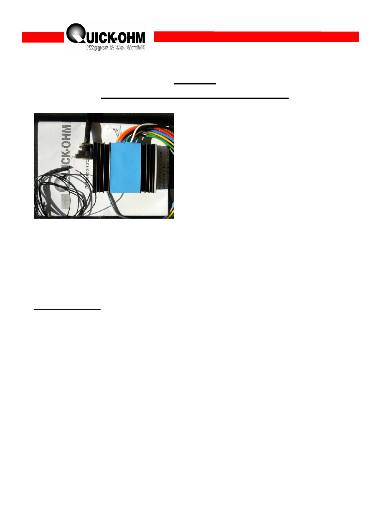
1 TEC - Controller QC-PC-C01C
1 Temperaturesensor NTC 10KΩ (β=3977K)
1 Potentiometer 10KΩ
1 Manual
Technial Data:
Dimensions: 65mm x 50mm x 20mm
Temperature range: -20°C…+50°C
Input voltage: 10V…24V
Max. output voltage: equal to input voltage
Max. output current: 10A
1. Basic information QC-PC-C01C
The QC-PC-C01C was designed as controller for cooling to adjust a TEC (Thermoelectric coller)
at a certain temperature. The controller is operated by low DC voltage and should not be exposed
to main voltage. To set up the controller electrical wiring is required, which request some basic
knowledge of electrical circuits. All wiring must be done without connection to the power supply.
Be aware that same components can be damaged or destroyed be incorrect use. Despite of low
voltage, high currents can occur and serious warming and the danger of fire can appear by using
wrong lead wires. Please read this instruction carefully and consult an electrician by any question.
If you remark any warming during operation, the controller must be switched off immediately.
Quick-Ohm Küpper & Co. GmbH
Components – Heat-Management - Ceramics
www.quick-ohm.com vXIII/07/nk
- 1 -
Page 2
2. Operating principle:
Temperatur
e
sensor
A TEC is able to transfer thermal power from one side of the module to the other by consuming
electrical power. The temperature drops on one side of the element, because of heat consumption
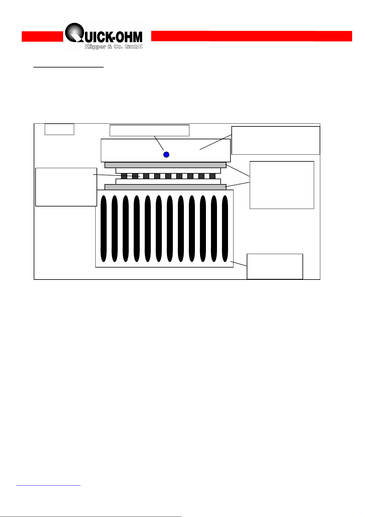
while it rises on the other side. For using this heatpump effect in a technical application, a setup
similar to figure 1 is to be built up.
figure 1:
Temp. controlled
area/ cold side
Thermal
TEC
(printing on
upper side)
conductive
(Paste, Foil,
etc.)
Heatsink/ hot
side
This is the basic setup for any TEC-Application. The area to be temperature controlled must be
equipped with a temperature sensor. On the opposite side, the removed heat must be dissipated to
the ambient. The size of the heatsink and the quality of the thermal contact to the TEC has the
biggest influence on the performance of the whole system. The gap between the TEC and the
mounted parts (hot/cold side) must be as small as possible and only a very little amount auf
thermal conductive should be used to avoid air inclusions in the contact areas. For further
information such as mechanical loads for a durable setup visit our website www.quick-ohm.com.
Quick-Ohm Küpper & Co. GmbH
Components – Heat-Management - Ceramics
www.quick-ohm.com vXIII/07/nk
- 2 -
Page 3

3. Electrical connection:
Potentiometer 10K
Ω
For operating the controller a DC power supply is needed. Please be aware that the controller has
no internal voltage or current limits and therefore will output the maximum voltage of the power
supply when the set-temperature is much lower than the actual temperature. Make sure, that the
maximum voltage of the power supply is within the range of the TEC. A series connection of
similar TECs can also be used to reduce the voltage for each TEC. Figure 2 shows the electrical
connection of the whole circuit, the colors follow the lead colors of the controller.
figure 2:
Controller
QC-PC-C01C
Orange
10..24V
Black
GND
+ -
Power supply
Blue
-PE
TEC
Yellow
Green
Grey
Red
Sensor
+PE
Signal
Temperatur-
Gnd
Sens/Poti
Control
Poti-Signal
Sensor
NTC 10KΩ
White
+5V Poti
10V … 24V
By following these instructions and using TECs from QUICK-OHM, the top side of the TEC will
get cold when the right wire showing in the direction of the viewer is red. Applied on the figure
above, the top side would be the warm side.
4. Temperature setting:
The controller has a working range from -20°C to + 50°C. Please notice, that the controller can
only be operated in cooling mode. 50°C can only be reached, when the hot side is above this
temperature. It could be useful to make marks on the potentiometer while the first use. By
adjusting some positions between the left and right stop of the potentiometer and while measuring
the temperature at that steps a small scale can be marked on the potentiometer.
It is possible to integrate a Display (QC-PC-D-100) in the setup. This device shows the settemperature as well as the actual temperature.
Quick-Ohm Küpper & Co. GmbH
Components – Heat-Management - Ceramics
www.quick-ohm.com vXIII/07/nk
- 3 -
Page 4

Controlling characteristics:
The following figures show a typical control mode of the temperature as function of time. In this
example, the set-temperature is lowered from ambient temperature to -15°C. The left figure shows
the current, the right figure the temperature. This shows an optimal behavior of the controller.
Stromverlauf Kühlen
Current while cooling
Temperaturv erlauf Kühlen
Temperature while cooling
120
100
80
60
urrent in %of Imax
Strom/100%xImax
40
20
0
1 3 5 7 9 11 13 15 17 19 21 2 3 25 27 29
Zeit
time in s time in s
50
30
10
1 3 5 7 9 11 13 15 17 19 21 23 25 27 29
Temperatur/°C
emperature in °C
-10
-30
-50
Zeit
5.Tips:
1. If the heatsink temperature is roughly above ambient temperature, the dimensions of the
heatsink are too small. A bigger heatsink and/or a fan can increase the heatexchange between the
heatsink ans te ambient.
2. The lowest temperature a single stage TEC can reach is around 70K below the temperature of
the hot side. Please regard that the temperature of the heatsink is always lower than the
temperature of the hot side because of the thermal resistance of the gap.
3. Mount the temperature for the controller close as possible to the TEC to improve the control
mode.
4. The heatsink must be able to dissipate the sum of cooling and electrical power as thermal
energy.
Quick-Ohm Küpper & Co. GmbH
Components – Heat-Management - Ceramics
www.quick-ohm.com vXIII/07/nk
- 4 -
 Loading...