

Quick SBC 600 NRG+ FR, SBC 700 NRG+ FR, SBC 750 NRG+ FR, SBC 950 NRG+ FR Manual Of Installation And Use
Page 1
REV 000a
PRELIMINARE
PRELIMINARY
High
Quality
SBC NRG
MEDIUM
SBC 600 NRG+ FR
SBC 700 NRG+ FR
SBC 750 NRG+ FR
SBC 950 NRG+ FR
Nautical
+
Equipment
Manuale di installazione ed uso
IT
Manual of installation and use SBC BATTERY CHARGER NRG+
EN
CARICABATTERIE SBC NRG+
Page 2

Page 3

IT
INDICE
Pag. 4 CARATTERISTICHE E INSTALLAZIONE
Pag. 5 INSTALLAZIONE:
ambiente di installazione
Pag. 6 INSTALLAZIONE:
alimentazione dell’apparecchio
Pag. 7 INSTALLAZIONE:
installazione dell’apparecchio - Segnali di controllo
Pag. 8 INSTALLAZIONE:
stato semplificato caricabatterie - Sensore temperatura batteria
Pag. 9 FUNZIONAMENTO:
pannello di controllo
Pag. 10 FUNZIONAMENTO:
caratteristiche di carica
Pag. 11 SEGNALAZIONI:
problemi con reset manuale
Pag. 12 SEGNALAZIONI:
problemi con reset automatico
Pag. 12 MANUTENZIONE
Pag. 13 DATI TECNICI
EN
INDEX
Pag. 14 CHARACTERISTICS AND INSTALLATION
Pag. 15 INSTALLATION:
installation site
Pag. 16 INSTALLATION:
equipment supply
Pag. 17 INSTALLATION:
single battery charger / parallel battery charger - Control signals
Pag. 18 INSTALLATION:
battery charger’s simplified status - Battery temperature sensor
Pag. 19 OPERATION:
control panel
Pag. 20 OPERATION:
charging characteristics
Pag. 21
Pag. 22 NOTIFICATION SIGNS:
Pag. 22 MAINTENANCE
Pag. 23 TECHNICAL DATA
NOTIFICATION SIGNS:
problems with manual reset
problems with automatic reset
SBC NRG+ MEDIUM IT EN R EV000A
33
Page 4
IT
CARATTERISTICHE E INSTALLAZIONE
CARICABATTERIE SERIE SBC NRG+
La lunga esperienza maturata nel settore della nautica ci ha permesso di evolvere la gamma di caricabatterie SBC, ora
denominata NRG+, con prestazioni superiori rispetto allo standard di mercato.
I vantaggi che i caricabatterie SBC NRG+ offrono sono:
• Caratteristica di carica a tre stadi IUoU.
• Elevata efficienza.
• Uscite multiple per caricare più gruppi di batterie (separatore di carica a MOSFET interno).
• Carica differenziata per batterie ad elettrolita liquido aperte o sigillate, Gel, AGM, Optima
• Fusibili di uscita integrati all’interno del caricabatterie (per ogni uscita).
• Protezione contro il surriscaldamento delle batterie (con sensori opzionali).
• Capacità di erogare piena potenza con bassa tensione di alimentazione di rete AC.
• Bassa ondulazione residua sull’uscita.
• Ingresso rete AC Universale 264 ÷ 83 Vac, 45 ÷ 66 Hz.
• Fattore di potenza (cos
• Compatibilità con i generatori.
• Protezioni di corto circuito, sovraccarico, sovratensione di uscita e surriscaldamento.
• Funzionamento in un ampio intervallo di temperature ambiente.
• Velocità variabile delle ventole di raffreddamento.
• Interfaccia utente a LED indicanti lo stato, gli errori e la corrente in uscita.
• Terminale LCD retroilluminato con interfaccia multilingua (opzionale).
• Compensazione di carica in funzione della temperatura delle batterie (1 sensore in dotazione, più sensori opzionali).
ϕ
) pari a 1.
®
, Li-Ion.
INSTALLAZIONE
l’installazione del caricabatterie deve essere effettuata da personale qualicato.
PRIMA DI UTILIZZARE IL CARICABATTERIE LEGGERE ATTENTAMENTE IL PRESENTE MANUALE D’USO.
IN CASO DI DUBBI CONTATTARE IL RIVENDITORE O IL SERVIZIO CLIENTI QUICK
In caso di discordanze o eventuali errori tra il testo tradotto e quello originario in italiano, fare riferimento al testo
italiano o inglese.
F
Questo dispositivo è stato progettato e realizzato per essere utilizzato su imbarcazioni da diporto.
Non è consentito un utilizzo differente senza autorizzazione scritta da parte della società Quick
F
I CARICABATTERIE SONO STATI PROGETTATI PER INSTALLAZIONI FISSE (USO INTERNO).
ATTENZIONE:
fisiche, sensoriali o mentali, mancanti di esperienza e cognizione senza che abbiano ricevuto una supervisione o
istruzione riguardante l’uso del dispositivo da parte di una persona responsabile alla loro sicurezza.
questo dispositivo non è inteso per l’uso da parte di persone (bambini inclusi) con ridotte capacità
®
.
®
.
ATTENZIONE:
I caricabatterie Quick
non si assume alcuna responsabilità per danni diretti o indiretti causati da un uso improprio dell’apparecchio, da un’errata
installazione o da possibili errori presenti in questo manuale.
L’APERTURA DEL CARICABATTERIE DA PARTE DI PERSONALE NON AUTORIZZATO FA DECADERE LA
GARANZIA.
LA CONFEZIONE CONTIENE:
utilizzare per il collegamento ai terminali di uscita) - sensore per la compensazione di carica.
4
i bambini dovrebbero essere sorvegliati per assicurarsi che non giochino con il dispositivo.
®
sono stati progettati e realizzati per gli scopi descritti in questo manuale d’uso. La società Quick®
caricabatterie - condizioni di garanzia - il presente manuale d’uso - connettore (da
SBC NRG+ MEDIUM IT EN R EV000A
Page 5
INSTALLAZIONE
EQUIPAGGIAMENTO NECESSARIO PER L’INSTALLAZIONE
A seconda del modello utilizzare le batterie e i cavi sui terminali di uscita specificati nella seguente tabella:
MODELLO SBC 600 NRG+ FR SBC 700 NRG+ FR SBC 750 NRG+ FR SBC 950 NRG+ FR
Tensione batterie
Capacità batterie
Sezione minima cavo di uscita
Numero di celle della batteria
La lunghezza massima dei cavi collegati ai terminali di uscita è di 4 metri.
230 ÷ 500 Ah 270 ÷ 600 Ah 140 ÷ 300 Ah 180 ÷ 400 Ah
16 mm
12 V 24 V
2
6 12
25 mm
2
10 mm
2
16 mm
2
IT
ATTENZIONE:
o sigillate), Gel, AGM, Optima
ATTENZIONE:
il caricabatterie deve essere utilizzato solo con batterie ricaricabili piombo/elettrolita liquido (aperte
®
, Li-Ion.
il caricabatterie non può essere utilizzato per ricaricare batterie non ricaricabili.
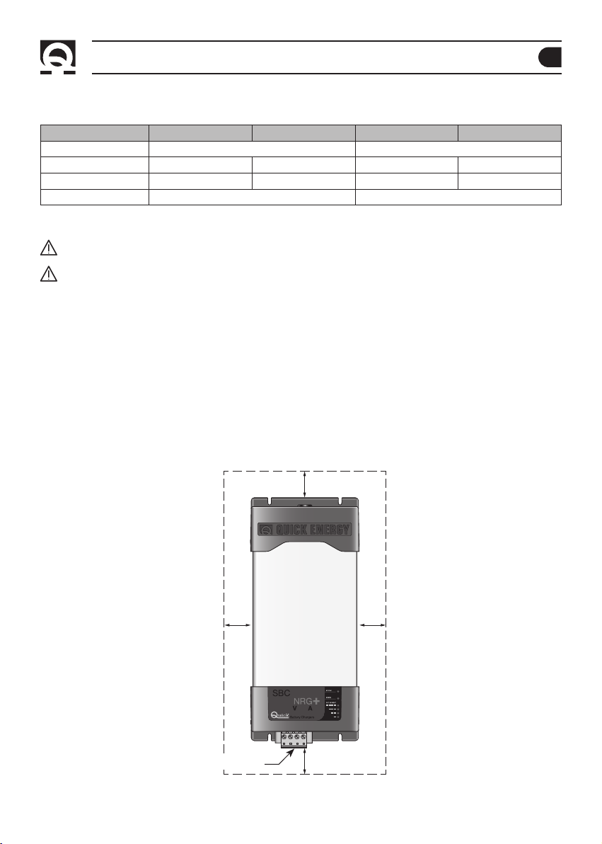
AMBIENTE DI INSTALLAZIONE
Installare il caricabatterie il più vicino possibile alle batterie in un luogo asciutto e ventilato per permet tere il funziona
mento dell’apparecchio in piena potenza.
Il caricabatterie può essere installato su un piano orizzontale o su una parete verticale con il connettore di uscita verso
il basso.
Il caricabatterie deve essere fissato al piano di appoggio tramite viti idonee a supportare il peso dell'apparecchio, ponen
do attenzione che quest’ultime non indeboliscano o causino rot ture alla struttura dell’imbarcazione.
Si consiglia l’installazione su una parete verticale poichè la convezione naturale del calore aiuta il raffreddamento
dell’apparecchio.
Il perimetro del caricabatterie (esclusa la base di appoggio) deve distare dalla vicinanza di pareti o oggetti come mini
mo 5 cm.
5 cm
5 cm 5 cm
-
-
-
SBC NRG+ MEDIUM IT EN R EV000A
CONNETTORE
5 cm
5
Page 6
IT
INSTALLAZIONE
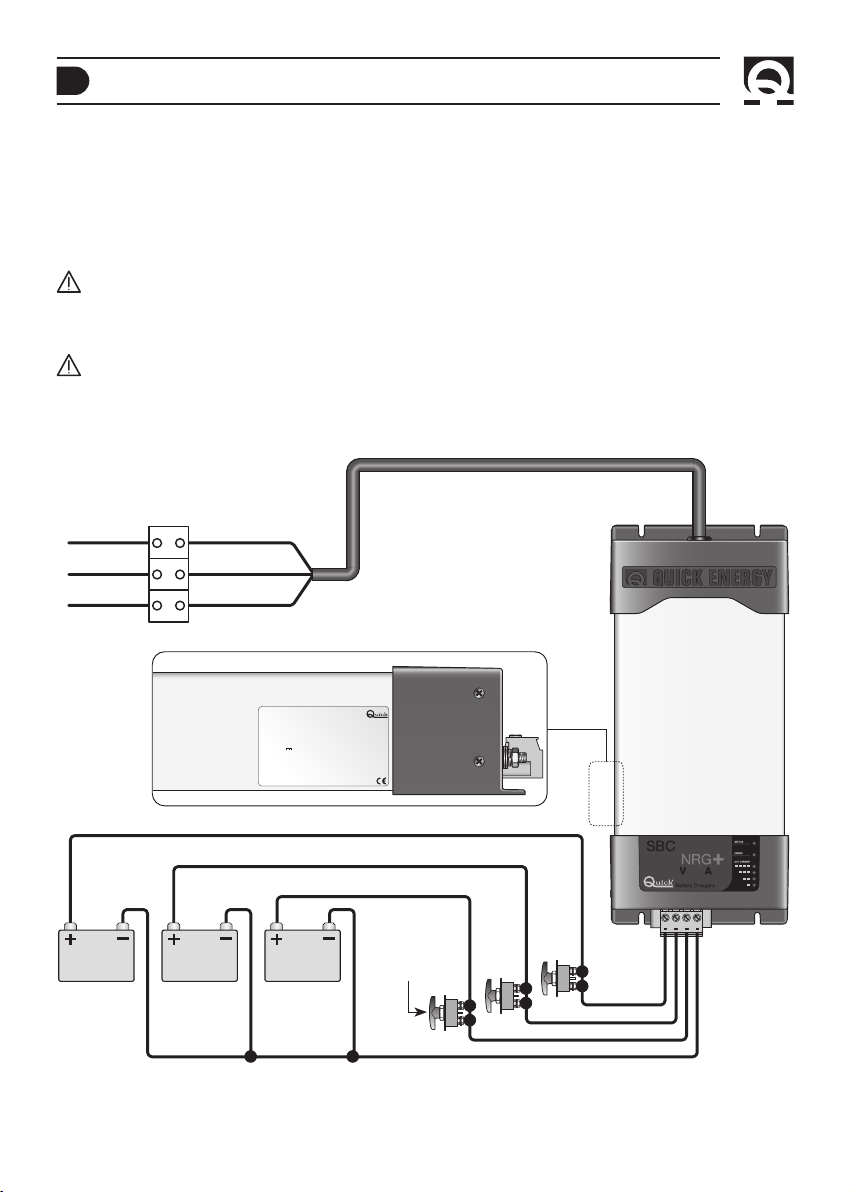
ALIMENTAZIONE DELL’APPARECCHIO
L’apparecchio è dotato del cavo di alimentazione per la rete AC. Per i collegamenti alla rete AC vedere fig. 1A. Prima di
alimentare il caricabatterie accertarsi che la tensione di alimentazione, riportata sull’etichetta dei dati di targa (fig. 1B),
corrisponda a quella fornita dalla rete AC.
Nell’impianto elettrico deve essere installato un interruttore di categoria sovratensione III per accendere e spegnere l’apparecchio.
Le connessioni alla rete AC devono essere realizzate in accordo alle norme locali relative agli impianti elettrici.
ATTENZIONE:
prima di collegare o scollegare il cavo AC del caricabatterie dalla rete AC accertarsi che quest’ultima
sia disconnessa tramite interruttore bipolare.
Prima di collegare o scollegare i cavi DC dai terminali di uscita del caricabatterie accertarsi che l’apparecchio sia
disconnesso, tramite interruttore bipolare, dalla rete AC e tramite staccabatteria dalle batterie.
ATTENZIONE:
Quick
nel caso in cui il cavo di alimentazione sia danneggiato, farlo sostituire da un centro assistenza
®
. Per evitare incidenti l’apparecchio deve essere aperto solo da personale autorizzato.
FIG.1 A
NEUTRO
TERRA
FASE
BAT TER IA
N° 3
FIG.1 B
BAT TER IA
GIALLO VERDE
MARRONE
N° 2
BLU
SBCXXXX NRG+ XXX XXV XXA XX XX
SN:XXXXXX Rev:XXX WY:XX/XX
XXXV,XXXV, 45-66Hz, X.XA MAX
INPUT:
~
XXA MAXIMUM
OUTPUT:
ABSORPTION XX.XV OL XX.XV Li-Ion
XX.XV SL/GEL/AGM XX.XV Optima
FLOAT XX.XV OL XXV Li-Ion XX.XV AGM
XX.XV SL/GEL/Optima
BAT TER IA
N° 1
®
®
STAC CABATT ERIE
6
SBC NRG+ MEDIUM IT EN R EV000A
Page 7
INSTALLAZIONE
IT
INSTALLAZIONE DELL’APPARECCHIO
Il polo positivo della batteria o del gruppo batterie deve essere collegato a uno dei terminali positivi del caricabatterie; il polo
negativo della batteria o del gruppo batterie al terminale negativo del caricabatterie (fig.1A).
Per effettuare i collegamenti utilizzare il connettore in dotazione con l’apparecchio.
Se si hanno solamente uno o due gruppi di batterie, collegare sempre l’uscita siglata come “MASTER”.
Questa è l’uscita principale del caricabatterie. Si consiglia di collegare all’uscita MASTER il gruppo di batterie più utilizzato
(tipicamente il gruppo servizi).
I terminali positivi di uscita non utilizzati devono rimanere liberi (non effettuare ponticelli tra i terminali).
ATTENZIONE:
l’utilizzo di cavi di sezione non adeguata e l’errata connessione dei terminali o delle giunzioni
elettriche possono provocare un surriscaldamento pericoloso dei terminali di collegamento e dei cavi.
FIG. 2
CAN IN CAN OUT
1
8
8
1
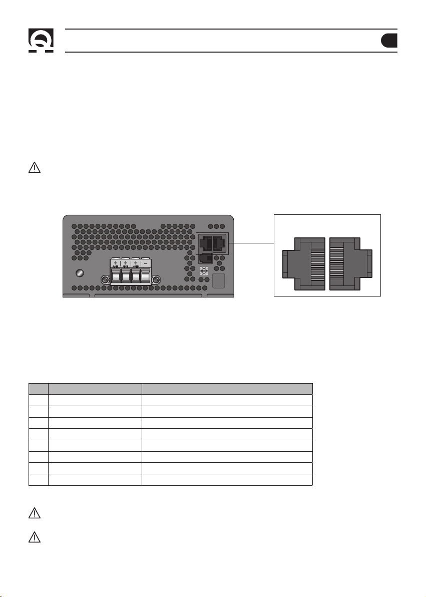
SEGNALI DI CONTROLLO
Il caricabatterie è dotato di due prese RJ45 definite “CAN IN” e “CAN OUT” sulle quali sono riportati i segnali utilizzabili per
il monitoraggio ed il controllo dell’apparecchio.
Di seguito si riporta la posizione e la descrizione dei segnali presenti sulle prese (fig. 2):
PINOUT PRESE RJ45
PIN CAN IN CAN OUT
1 Segnale CANL Segnale CANL
2 Segnale CANH Segnale CANH
3 RISERVATO Non collegato
4 RISERVATO Stato semplificato del caricabatterie (+V uscita, 20 mA max)
5 RISERVATO Negativo caricabatterie
6 RISERVATO Non collegato
7 Non collegato Tensione uscita MASTER (corrente limitata a 100 mA)
8 Terminatore CAN BUS (120 ohm) Terminatore CAN bus (120 ohm)
ATTENZIONE:
durante la carica le batterie possono generare gas esplosivi. Evitare scintille o fiamme. Provvedere ad
un’adeguata ventilazione dell’ambiente batterie durante la carica.
ATTENZIONE:
prima di effettuare il collegamento alle batterie verificare attentamente la polarità dei cavi provenienti
dalla batteria. Infatti un’inversione di polarità potrebbe danneggiare seriamente il caricabatterie anche se protetto
tramite fusibili.
SBC NRG+ MEDIUM IT EN R EV000A
7
Page 8
IT
INSTALLAZIONE
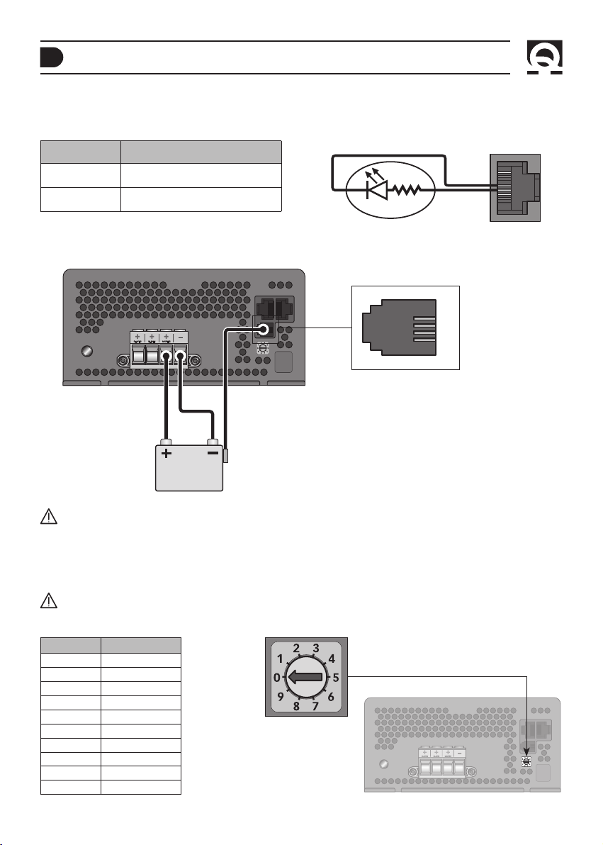
STATO SEMPLIFICATO CAR IC AB ATTERIE
Sul pin 4 della presa RJ45 CAN OUT è presente un segnale che fornisce l’indicazione sullo stato di funzionamento del caricabatterie (presenza o assenza di problemi) (fig 3).
COLLEGAMENTO
PIN 4 CAN OUT
ALTA IMPEDENZA
+ V USCITA
STATO
Caricabatterie spento o presenza di
problemi con reset manuale.
Caricabatterie acceso e assenza di
problemi con reset manuale.
FIG. 3
5
4
SENSORE TEMPERATURA BATTERIA
CAN OUT
Sulla presa RJ11 è possibile collegare un sensore temperatura per le batterie (KTBRJ).
2
3
CONNETTORE
SENSORE BATTERIE
KTBR J SENSORE
TEMPERATURA
ATTENZIONE
BATTERIA
: nel caso in cui sia collegata al caricabatterie un’interfaccia KTB4N (opzionale, con uno o più sensori),
il sensore KTBRJ collegato alla presa RJ11 sarà automaticamente disattivato.
SELEZIONE DEL TIPO DI BATTERIE
Tramite il selettore presente sul pannello frontale del carica batterie è possibile selezionare il tipo di batterie da caricare.
ATTENZIONE:
selezionare il tipo di batterie solo a caricabatterie spento.
Fare riferimento alla seguente tabella per selezionare il tipo di batterie da caricare:
NUMERO TIPO BATTERIE
EL aperta
0*
1
EL sigillata
2
Gel
3
AGM
4
5
6
7
8
9
®
Optima
Li-lon
RISERVATO
RISERVATO
RISERVATO
RISERVATO
* Impostazione di fabbrica
8
SBC NRG+ MEDIUM IT EN R EV000A
Page 9

FUNZIONAMENTO
PANNELLO DI CONTROLLO
Il pannello di controllo è composto da 6 LED:
n° 1 LED STATUS, n°1 LED ERROR, n° 4 LED OUT CURRENT
Le indicazioni fornite dai LED sono riportate di seguito:
LED STATUS
COLORE LED DESCRIZIONE
SPENTO
VERDE
ARANCIONE
ROSSO
LAMPEGGIO VELOCE
LAMPEGGIO LENTO
IMPULSO VERDE BREVE
IMPULSO VERDE
LED ERROR
COLORE LED DESCRIZIONE
SPENTO
LAMPEGGIANTE
ROSSO
Tensione di rete assente o presenza di errori
Fase FLOAT
Fase ABSORPTION
Fase BULK
Riduzione di potenza attiva
Compensazione di carica attiva
Modalità di monitor attiva
Modalità Stand-by attiva
Nessun problema
Problema con reset manuale (vedere tabella codici errore)
Problema con reset automatico (vedere tabella codici errore)
FUNZIONAMENTO
LED STATUS
LED ERROR
LED OUT CURRENT
IT
LED OUT CURRENT
COLORE LED DESCRIZIONE
ROSSO
ARANCIONE
ARANCIONE
VERDE
SBC NRG+ MEDIUM IT EN R EV000A
Corrente in uscita >75% della corrente massima
Corrente in uscita >50% della corrente massima
Corrente in uscita >25% della corrente massima
Corrente in uscita > 2% della corrente massima
9
Page 10

IT
FUNZIONAMENTO
CARATTERISTICHE DI CARICA
La carica avviene attraverso 3 fasi:
Fase BULK (corrente costante)
Le batterie richiedono più corrente di quanto il caricabatterie possa fornire. La corrente viene limitata al valore
nominale massimo di uscita o ad un valore inferiore se sono presenti fattori che determinano una riduzione di potenza
dell’apparecchio. Il caricabatterie può entrare in questa fase durante l’accensione, quando le batterie sono molto scariche
o quando viene collegato un carico di elevata entità.
Fase ABSORPTION (tensione costante)
Il caricabatteria carica le batterie alla tensione costante di ABSORPTION erogando la corrente che necessitano quando la
corrente richiesta è superiore alla soglia di passaggio tra ABSORRPTION e FLOAT e inferiore al valore nominale massimo di
uscita o ad un valore inferiore se sono presenti fattori che determinano una riduzione di potenza dell’apparecchio.
Fase FLOAT (mantenimento)
Il caricabatterie carica le batterie alla tensione costante di FLOAT quando la corrente richiesta è inferiore alla soglia di
passaggio tra ABSORPTION e FLOAT. In questa fase le batterie raggiungendo la massima carica, tenderanno ad assorbire
correnti sempre più basse. Questa soluzione consente di mantenere le batterie sempre in carica senza il rischio di
sovraccarico.
BULK ABSORPTION FLOAT NUOVO CICLO
(V)
V ABSORPTION *
V FLOAT *
(I)
IMAX
ITH ABSORPTION-FLOAT
* A seconda del tipo di carica selezionata.
L’impostazione di fabbrica della soglia di passaggio tra
della corrente di uscita.
10
ABSORPTION
e
FLOAT
è pari al 20% del valore nominale massimo
SBC NRG+ MEDIUM IT EN R EV000A
TEMPO
TEMPO
Page 11

SEGNALAZIONI
IT
SEGNALAZIONI
PROBLEMI CON RESET MANUALE
Per eliminare i problemi con reset manuale bisogna rimuovere la causa che li ha generati, disconnettere il caricabatterie
dalla rete AC per almeno 10 secondi e riconnetterlo.
Con questa tipologia di problemi il caricabatterie interrompe l’erogazione di potenza (eccetto per il problema 12, dove la
tensione di uscita viene forzata al valore di FLOAT).
Il tipo di problema viene segnalato facendo lampeggiare il LED ERROR.
Fare riferimento alla seguente tabella per individuare il tipo di problema:
LAMPEGGI
LED
2
3
5
6
9
10
11
12
MESSAGGIO DESCRIZIONE
Fusibile di uscita interrotto
Sovratensione in uscita
Sovraccarico prolungato
Entrambe le ventole
sono bloccate
Due o più caricabatterie
nello stesso gruppo
con la stessa priorità
Sensori interni di temperatura
non funzionanti
Fase di BULK
prolungata
Fase di ABSORBTION
prolungata
Probabile inversione di polarità nel collegamento delle batterie ai morsetti di uscita del
caricabatterie.
Il problema richiede una verifica da parte di un centro assistenza Quick
Protezione software.
Il caricabatterie a causa di un malfunzionamento interno ha erogato, per un brevissimo
istante, una tensione superiore al valore nominale.
Il problema richiede una verifica da parte di un centro assistenza Quick®.
Il caricabatterie ha erogato il massimo della corrente ad una tensione inferiore alla metà del
valore nominale di uscita per troppo tempo.
Verificare l’assorbimento del gruppo batterie e gli utilizzatori collegati.
Entrambe le ventole di raffreddamento sono ferme per cause esterne (corpi estranei che
bloccano il movimento delle pale) o malfunzionamento.
Il problema richiede una verifica da parte di un centro assistenza Quick
Verificare la corretta configurazione del gruppo e la priorità dei caricabatterie collegati in
rete utilizzando il terminale RDS1562 (opzionale).
Entrambi i sensori interni di temperatura non sono funzionanti.
Il problema richiede una verifica da parte di un centro assistenza Quick
E’ stato superato il tempo massimo di 8 ore per la fase di
Verificare lo stato dei gruppi batterie e l’assorbimento degli utilizzatori collegati ad essi.
E’ stato superato il tempo massimo di 24 ore per la fase di
Verificare lo stato dei gruppi batterie e l’assorbimento degli utilizzatori collegati ad essi.
BULK
.
ABSORPTION
®
®
.
®
.
.
SBC NRG+ MEDIUM IT EN R EV000A
11
Page 12

IT
SEGNALAZIONI - MANUTENZIONE
PROBLEMI CON RESET AUTOMATICO
I messaggi dei problemi con reset automatico scompaiono non appena viene a mancare la condizione che ha provocato il
problema.
LAMPEGGI
MESSAGGIO DESCRIZIONE
LED
Corto circuito o
1
sovraccarico in uscita
Verificare i cablaggi di uscita, i gruppi di batterie e gli utilizzatori collegati al caricabatterie.
I seguenti errori verranno visualizzati accendendo il LED ROSSO in modo fisso e segnalando un errore nel terminale LCD
(opzionale)
PROBLEMA DESCRIZIONE
Alta temperatura La temperatura ambiente dove è installato il caricabatterie è superiore alla soglia massima consentita per il regolare
Ventilatore bloccato Uno dei due ventilatori di raffreddamento è bloccato per cause esterne (corpi estranei che bloccano il movimento delle
AC bassa La tensione di rete AC è minore di 108 Vac.
AC assente La tensione di rete AC è minore di 83 Vac.
Batteria fredda La temperatura misurata dal sensore o dai sensori opzionali, installato/i sulle batterie, è minore di -15°C.
Batteria calda La temperatura misurata dal sensore o dai sensori opzionali, installato/i sulle batterie, è maggiore di +50°C.
Avaria Sensore Malfunzionamento di uno dei due sensori interni di temperatura del caricabatterie.
Errore CAN Il sistema ha rilevato degli errori di comunicazione sulla CAN BUS.
funzionamento.
Verificare l’ambiente di installazione e il posizionamento del caricabatterie.
pale) o per malfunzionamento.
Il caricabatterie limita il valore massimo della corrente in uscita.
Il problema richiede una verifica da parte di un centro assistenza Quick
Il caricabatterie effettuerà una riduzione della massima corrente di uscita erogando come valore massimo il 70% della
corrente nominale massima di uscita, riducendo l’assorbimento di corrente dalla rete AC.
L’erogazione della massima corrente di uscita riprenderà quando la tensione di rete ritornerà ad un valore superiore
a 108 Vac.
Il caricabatterie sospende l’erogazione della potenza di uscita che riprenderà quando la tensione di rete ritornerà ad
un valore superiore a 83 Vac.
Il caricabatterie sospende l’erogazione di potenza in uscita che riprenderà quando la temperatura ritornerà ad un
valore maggiore di -15°C.
Il caricabatterie sospende l’erogazione di potenza in uscita che riprenderà quando la temperatura ritornerà ad un
valore minore di +50°C.
Il caricabatterie limita, se necessario, il valore massimo della corrente di uscita.
Il problema richiede una verifica da parte di un centro assistenza Quick
Se questo messaggio dovesse comparire frequentemente, verificare il cablaggio della rete CAN.
®
.
®
.
MANUTENZIONE
Il caricabatterie non richiede una particolare manutenzione. Per assicurare il funzionamento ottimale dell’apparecchio
verificare, una volta all’anno, i cavi e le connessioni elettriche.
12
SBC NRG+ MEDIUM IT EN R EV000A
Page 13

DATI TECNICI
IT
CARATTERISTICHE TECNICHE
MODELLO SBC 600 NRG+ FR SBC 700 NRG+ FR SBC 750 NRG+ FR SBC 950 NRG+ FR
CARATTERISTICHE DI USCITA
Corrente di uscita massima
Tensione di carica in ABSORPTION
Tensione di carica in FLOAT
Assorbimento DC dalle batterie
Ondulazione residua
Caratteristiche di carica Automatica a tre stadi IUoU
Numero di uscite
CARATTERISTICHE DI INGRESSO
Tensione di alimentazione
Frequenza 45÷66 Hz
Assorbimento massimo
(230/240 Vac)
(5)
Assorbimento massimo (120 Vac)
Fattore di potenza (cos ϕ)
(5)
Efficienza
PROTEZIONI
Inversione di polarità
Sovraccarico Si
Cortocircuito in uscita Si
Sovratensione in uscita
Surriscaldamento Si
Sovratemperatura batterie Si, opzionale
CARATTERISTICHE AMBIENTALI
Temperatura operativa -15 ÷ +70 °C, con riduzione di potenza lineare sopra +50 °C
Raffreddamento Forzato, con velocità ventole variabili
Umidità Max. 95% RV non condensante
CONTENITORE
Materiale Alluminio
Dimensioni (LxAxP) 170 x 391 x 82 mm
Peso 3,1 kg
GENERALI
Interfaccia CAN bus Sì
Compensazione di carica Sì, 1 sensore in dotazione, più sensori opzionali (max 128 sensori di temperatura batterie)
Standard sicurezza EN 60335-2-29
Standard EMC EN 55022/A - FCC TITLE 47 PART 15 SUBPART B CLASS A
(1)
Valore massimo nominale in funzionamento normale o in corto circuito.
(2)
Con caricabatterie non alimentato dalla rete AC, modalità monitor disattivata e terminale LCD non collegato.
(3)
Al 50% della corrente nominale massima di uscita su carico resistivo.
(4)
Ogni uscita è in grado di erogare il valore massimo di corrente nominale. La somma delle correnti erogate da ogni uscita non può superare il
valore massimo nominale dell'apparecchio.
(5)
Con tensione di rete pari a 230 Vac e corrente di uscita pari al valore nominale massimo.
(6)
Con tensione di rete pari a 120 Vac e corrente di uscita pari al valore nominale massimo.
(7)
La protezione puo essere inefficace in alcune condizioni operative.
(8)
Doppio controllo software/hardware.
QUICK® SI RISERVA IL DIRITTO DI APPORTARE MODIFICHE ALLE CARATTERISTICHE TECNICHE DELL’APPARECCHIO E AL CONTENUTO DI QUESTO MANUALE SENZA ALCUN PREAVVISO.
SBC NRG+ MEDIUM IT EN R EV000A
(1)
(2)
(3)
(4)
50 A 60 A 30 A 40 A
• 14,1 Vdc EL aperta
• 14,2 Vdc Li-Ion
• 14,4 Vdc EL sigillata / Gel / AGM
• 14,7 Vdc Optima
• 13,4 Vdc EL aperta
• 13,5 Vdc Li-Ion
• 13,6 Vdc AGM
• 13,8 Vdc EL sigillata / Gel / Optima
®
®
• 28,2 Vdc EL aperta
• 28,4 Vdc Li-Ion
• 28,8 Vdc EL sigillata / Gel / AGM
• 29,4 Vdc Optima
• 26,8 Vdc EL aperta
• 27,0 Vdc Li-Ion
• 27,2 Vdc AGM
• 27,6 Vdc EL sigillata / Gel / Optima
®
< 3,5 mA < 5 mA
< 100 mV RMS < 150 mV RMS
3
264 ÷ 83 Vac,
con riduzione di potenza sotto 108 Vac
®
3,4 A 3,9 A 4,2 A 5,1 A
(6)
(5)
6,5 A 7,5 A 7,9 A 10,0 A
1,00
≥ 90% ≥ 92%
(7)
(8)
Si, tramite fusibile
Si
13
Page 14

EN
CHARACTERISTICS AND INSTALLATION
SBC NRG+ SERIES BATTERY CHARGER
The long experience we have in the nautical field has given us the ability to evolve the range of SBC battery chargers, now
called NRG+, with superior performance to those currently on the market.
The advantages which the SBC NRG+ battery chargers offer, are:
• Three stage IUoU battery charging.
• High efficiency.
• Multiple outputs in order to charge more groups of batteries (MOSFET charge separator inside).
• Differentiated charging for open or sealed liquid electrolite, Gel, AGM, Optima
• Integrated output fuses inside the battery chargers (for each output).
• Thermal battery protection (with optional sensors).
• Capacity of supplying full power with low AC mains voltage.
• Low residual fluctuation on output.
• Universal AC supply input 264 ÷ 83 Vac, 45 ÷ 66 Hz.
• Power factor (cos
• Compatible with the generators.
• Short circuit, overloading, output overvoltage and overheating protection.
• Can work in a wide range of ambient temperatures.
• Variable speed for the cooling fan.
• User interface via LEDs that signal the status, errors and the output current.
• Backlit LCD terminal with multi-language interface (optional).
• Charge is compensated according to the temperature of the batteries (1 sensor supplied; more sensors optional).
ϕ
) equal to 1.
®
, Li-Ion batteries.
INSTALLATION
The installation of the battery charger must be carried out by qualied personnel.
BEFORE USING THE BATTERY CHARGER CAREFULLY READ THIS USER’S MANUAL.
IF IN DOUBT, CONTACT YOUR NEAREST DEALER OR “QUICK
In case of discordance or errors in translation between the translated version and the original text in Italian,
reference will be made to the Italian or English text.
F
This device was designed and constructed for use on recreational crafts.
Other forms of use are not permitted without written authorization from the company Quick
F
THE BATTERY CHARGERS ARE DESIGNED FOR FIXED INTERNAL INSTALLATIONS ONLY.
WARNING:
or mental capabilities, or lack of experience and knowledge, unless they have been given supervision or instruction
concerning use of the appliance by a person responsible for their safety.
this appliance is not intended for use by persons (including children) with reduced physical, sensory
®
” CUSTOMER SERVICE.
®
.
WARNING:
“Quick®” battery chargers have been designed and made for the reasons described in this user’s manual. The “Quick®”
Company does not accept any responsibility for direct or indirect damage caused by improper use of the equipment, bad
installation or by possible errors occurring in this manual.
OPENING OF THE BATTERY CHARGER BY UNAUTHORISED PERSONNEL MAKES THE WARRANTY VOID.
THE PACKAGE CONTAINS:
output terminals) - charge compensation sensor.
14
children should be supervised to ensure that they do not play with the appliance.
battery charger - conditions of warranty - user’s manual - connector (to connect to the
SBC NRG+ MEDIUM IT EN R EV000A
Page 15

INSTALLATION
NECESSARY EQUIPMENT FOR INSTALLATION
Depending upon model, use the batteries and cables on the output terminals as specified in the following table:
MODEL SBC 600 NRG+ FR SBC 700 NRG+ FR SBC 750 NRG+ FR SBC 950 NRG+ FR
Battery voltage
Battery capacity
Minimum output cable size
Number of battery cells
The wires connected to the output terminals must have a maximum length of 4 meters.
230 ÷ 500 Ah 270 ÷ 600 Ah 140 ÷ 300 Ah 180 ÷ 400 Ah
16 mm
12 V 24 V
2
6 12
25 mm
2
10 mm
2
16 mm
2
EN
WARNING:
sealed), Gel, AGM, Optima
WARNING:
the battery charger must be used only with re-chargeable lead/liquid electrolytic batteries (open or
®
, Li-Ion.
the battery charger can not be used to recharge non rechargeable batteries.
INSTALLATION SITE
Install the battery charger as close as possible to the batteries in a dry and airy spot, to allow the correct operation of
the device at full power.
The battery charger can be installed on a horizontal surface or vertical wall paying attention that the output connector
faces downwards.
The battery charger must be fixed to the support surface with screws strong enough to support its weight, paying atten
tion that they do not weaken or cause cracks to the boat structure.
Vertical installation is recommended since the natural convection of the heat will favour the cooling of the device.
The perimeter of the battery charger (excluding the suppor t base) must be kept at a distance from walls or objects by a
minimum of 5 cm.
5 cm
5 cm 5 cm
SBC NRG+ MEDIUM IT EN R EV000A
CONNECTOR
5 cm
15
Page 16

EN
INSTALLATION
EQUIPMENT SUPPLY
The equipment already includes a AC power cord. For connections to an AC mains see fig.1A.
Before powering up the battery charger check that the power supply voltage, described on the rating label (fig.1B), corresponds to that supplied by the AC mains.
An overvoltage category III switch must be installed in the electrical circuit for the sole use of switching the equipment
ON/OFF.
The connections to the AC mains must be carried out according to local electrical codes.
WARNING:
before connecting or disconnecting the battery charger’s AC cord from the AC mains, please make sure
it is disconnected by bipolar switch.
Before connecting or disconnecting the DC wires from the battery charger’s output terminals, please ensure that the
device is disconnected by means of bipolar switch, from the AC mains and by means of a battery isolator from the
batteries.
WARNING:
in cases where the AC power cord could be damaged, have this changed by a “Quick®” service centre.
In order to avoid accidents, the equipment must only be opened by authorised personnel.
FIG.1 A
NEUTRAL
EARTH
LIVE
BAT TERY
N° 3
FIG.1 B
BAT TERY
YELLOW GREEN
BROWN
N° 2
BLUE
SBCXXXX NRG+ XXX XXV XXA XX XX
SN:XXXXXX Rev:XXX WY:XX/XX
XXXV,XXXV, 45-66Hz, X.XA MAX
INPUT:
~
XXA MAXIMUM
OUTPUT:
ABSORPTION XX.XV OL XX.XV Li-Ion
XX.XV SL/GEL/AGM XX.XV Optima
FLOAT XX.XV OL XXV Li-Ion XX.XV AGM
XX.XV SL/GEL/Optima
BAT TERY
N° 1
®
®
BAT TERY
SWITCHES
16
SBC NRG+ MEDIUM IT EN R EV000A
Page 17

INSTALLATION
EN
INSTALL ATION
The positive terminal of the battery or of the group of batteries must be connected to one of the positive terminals of
the battery charger. The negative terminal of the battery or of the group of batteries must be connected to the negative terminal of the battery charger (fig. 1A). To make the connections use the connector supplied with the equipment.
If the installation has only one or two groups of batteries, always connect the output marked “MASTER”. This is the main
output of the battery charger. It is advisable to connect the group of batteries which are used more often (typically the
service group) to the MASTER output terminal.
The positive output terminals that are not used must be kept free (do not bridge the terminals).
WARNING:
the use of inadequate size cables and the incorrect connection of terminals or electrical joints may result in dangerous overheating of the connecting terminals or cables.
FIG. 2
CAN IN CAN OUT
1
8
8
1
CONTROL SIGNALS
The battery charger is provided with two RJ45 female defined “CAN IN” and “CAN OUT” on which are present the signals
which can be used for monitoring and controlling the equipment.
The position and description of the signals on the female RJ45 are listed below (fig. 2):
RJ45 PINOUT SOCKETS
PIN CAN IN CAN OUT
1 CANL Signal CANL Signal
2 CANH Signal CANH Signal
3 RESERVED Unconnected
4 RESERVED Basic state of the battery charger (+V output, 20 mA max)
5 RESERVED Negative of the battery charger
6 RESERVED Unconnected
7 Unconnected MASTER output voltage (current limited to 100 mA)
8 CAN BUS terminator (120 ohm) CAN bus terminator (120 ohm)
WARNING:
during charge, batteries can generate explosive gases, therefore avoid sparks or naked flames. Provide
adequate ventilation to the battery area whilst charging.
WARNING:
before connecting the batteries check the polarity of the cables from the battery. Reversing the polarity,
could seriously damage the battery charger even if protected by fuses.
SBC NRG+ MEDIUM IT EN R EV000A
17
Page 18

EN
INSTALLATION
BATTERY CHARGER’S SIMPLIFIED STATUS
On pin 4 of the RJ45 CAN OUT socket, a signal which indicates the operating status of the battery charger (presence or
absence of problems) is located (Fig. 3).
PIN 4 CAN OUT
CONNECTION
HIGH IMPEDANCE
+ V OUTPUT
STATE
Battery charger switched off or presence
of problems requiring manual reset.
Battery charger switched on and absence
of any problem requiring manual reset.
FIG. 3
5
4
BATTERY TEMPERATURE SENSOR
A temperature sensor for the batteries (KTBRJ) can be connected to the RJ11 socket.
2
3
BATTERY
SENSOR CONNECTOR
KTBR J
TEMPERATURE SENSOR
WARNING
BATTERY
: in case a KTB4N interface (optional, with one or more sensors) is connected, the KTBRJ sensor
connected to the RJ11 socket will be automatically disabled.
BATTERY TYPE SELECTION
Select the type of battery to be charged by turning the selector on the front panel of the battery charger.
WARNING:
select the battery type only when the battery charger is switched off.
Refer to the table below to select the type of batteries you want to charge:
NUMBER BATTERY TYPE
EL open
0*
1
EL sealed
2
Gel
3
AGM
4
5
6
7
8
9
®
Optima
Li-lon
RESERVED
RESERVED
RESERVED
RESERVED
* Factory settings
CAN OUT
18
SBC NRG+ MEDIUM IT EN R EV000A
Page 19

OPERATION
CONTROL PANEL
The control panel is made up of 6 LEDs:
no.1 LED STATUS, no.1 LED ERROR, no. 4 LED OUT CURRENT
The information supplied by the LEDs are listed as below:
LED STATUS
LED COLOUR DESCRIPTION
OFF
GREEN
ORANGE
RED
QUICK FLASH
SLOW FLASH
SHORT GREEN PULSE
GREEN PULSE
No mains power or presence of errors
FLOAT phase
ABSORPTION phase
BULK phase
Active power reduction
Charge compensation active
Active monitor mode
Active Stand-by mode
OPERATION
LED STATUS
LED ERROR
LED OUT CURRENT
EN
LED ERROR
LED COLOUR DESCRIPTION
OFF
FLASHING
RED
No problem
Problem with manual reset (see code page errors table)
Problem with automatic reset (see code page errors table)
LED OUT CURRENT
LED COLOUR DESCRIPTION
RED
ORANGE
ORANGE
GREEN
SBC NRG+ MEDIUM IT EN R EV000A
Output current is >75% of the max current
Output current is >50% of the max current
Output current is >25% of the max current
Output current is >2% of the max current
19
Page 20

EN
OPERATION
CHARGING CHARACTERISTICS
Charging procedure takes place in 3 phases:
BULK phase (constant current)
The batteries need more current than the battery charger can supply. Current is limited to the maximum rated output or
to a lower value if factors which determine a power reduction of the device are present. The battery charger can enter
this phase during start-up, when the batteries are low or when a high load is connected.
ABSORPTION phase (constant voltage)
The battery charger charges the batteries at a constant ABSORPTION voltage supplying the current needed when the
current requested is greater than the transition threshold between ABSORPTION and FLOAT and less than the maximum
output value or at a lower value if factors which determine a power reduction of the device are present.
FLOAT phase (maintenance)
The battery charger charges the batteries at constant FLOAT voltage when the current required is less than the transition
threshold between ABSORPTION and FLOAT. In this phase, as the batteries reach maximum capacity, they will tend to
absorb increasingly low current. This float phase will allow the batteries to be on charge without risking overload.
(V)
BULK ABSORPTION FLOAT NEW CYCLE
V ABSORPTION *
V FLOAT *
(I)
IMAX
ITH ABSORPTION-FLOAT
TIME
TIME
* Depending on the type of charge selected.
The factory setting of the transition threshold between ABSORPTION and FLOAT is equal to 20% of the maximum nominal
value of the output current.
20
SBC NRG+ MEDIUM IT EN R EV000A
Page 21

NOTIFICATION SIGNS
EN
NOTIFICATION SIGNS
PROBLEMS WITH MANUAL RESET
In order to solve problems with manual reset it is necessary to remove the cause that generated it, disconnect the battery
charger from the AC mains for 10 seconds and then reconnect it.
With this type of problems, the battery charger stops supplying power (except for problem 12, in which output voltage is
forced to the FLOAT value).
The ERROR LED flashes to warn about the kind of problem.
Refer to the table below to identify the kind of problem:
LED
FLASHES
MESSAGE DESCRIPTION
Output fuse open
2
3
Output overvoltage
5
Extended output overload
6
Both fans blocked
Almost two chargers in a
9
group with the same priority
Internal temperature sensors
10
fault
11
BULK phase too long
12
ABSORPTION phase too long
Likely inversion of polarity in the connection of the batteries to the battery charger’s output
terminals.
The problem requires a check by a Quick
Software protection.
The battery charger, due to an internal malfunction, supplied for a very short time a higher
voltage than the rated value.
The problem requires a check by a Quick® service center.
The battery charger has supplied the maximum current at a lower voltage value than half the
output rated value for too long.
Check the absorption of the battery bank and the connected loads.
Both cooling fans are stopped for external causes (foreign bodies which block the blades
movement) or malfunctioning.
The problem requires a check by a Quick® service center.
Check the correct setting of the group and the priority of the battery chargers connected to
the network, by means of the RDS 1562 terminal (optional).
Both internal temperature sensors are not working.
The problem requires a check by a Quick® service center.
The maximum time limit of 8 hours for the BULK phase has been exceeded.
Check the status of the battery banks and the absorption of the loads connected to them.
The maximum time limit of 24 hours for the ABSORPTION phase has been exceeded.
Check the status of the battery banks and the absorption of the loads connected to them.
®
service center.
SBC NRG+ MEDIUM IT EN R EV000A
21
Page 22

EN
NOTIFICATION SIGNS - MAINTENANCE
PROBLEMS WITH AUTOMATIC RESET
The notifications of the problems with automatic reset will no longer be displayed as soon as the condition which caused
the problem disappears.
LED
FLASHES
MESSAGE DESCRIPTION
Output short circuit
1
or overload
Check the output wiring, the battery bank and the equipment connected to the battery charger.
The RED LED will come on steadily and an error will be displayed in the LCD terminal (optional) to signal the following errors
PROBLEM DESCRIPTION
Over temperature The ambient temperature where the battery charger is installed exceeds the max allowable threshold for regular
Blocked fan One of the two cooling fans is blocked due to external causes (foreign bodies which block the blades movement) or for
AC low The AC mains voltage is lower than 108 Vac.
AC fail The AC mains voltage is lower 83 Vac.
Cold battery The temperature measured by the sensor or the optional sensors of the batteries is lower than -15°C.
Hot battery The temperature measured by the sensor or the optional sensors of the batteries is highter than +50°C.
Sensor fault Failure of one of the two battery charger’s internal temperature sensors. The battery charger limits, if necessary, the
CAN error The system detected some communication errors on the CAN BUS. If this message appears frequently, check the CAN
operation.
Check the installation environment and its placement.
malfunctionig. The battery charger limits the value of the maximum output current.
The problem requires a check by a Quick
The battery charger will carry out a reduction of the maximum output current by supplying as maximum value the 70%
of the output maximum rated current, thus reducing the current absorption from the AC mains.
The supply of the maximum output current will start again once the network voltage increase back to a higher value
than 108 Vac.
The battery charger suspends the ouput power supply, which will start again once the mains voltage go back to a higher
value than 83 Vac.
The battery charger suspends the output power supply which will start again once the temperature will go back to a
higher value than -15°C.
The battery charger suspends the output power supply which will start again once the temperature will go back to a
lower value than +50°C.
maximum output current value.
The problem requires a check by a Quick
network wiring.
®
service center.
®
service center.
MAINTENANCE
The battery charger does not need any maintenance. To ensure optimum performance from the equipment, once a year
check the cables and the electrical connections.
22
SBC NRG+ MEDIUM IT EN R EV000A
Page 23

TECHNICAL DATA
TECH NICAL DATA
MODEL SBC 600 NRG+ FR SBC 700 NRG+ FR SBC 750 NRG+ FR SBC 950 NRG+ FR
OUTPUT CHARACTERISTICS
Maximum output current
Charge ABSORPTION voltage
Charge FLOAT voltage
DC absorption from the batteries
Residual ripple
Charging characteristics Automatic in three stages IUoU
Number of outputs
INPUT CHARACTERISTICS
Supply voltage
Frequency 45÷66 Hz
Maximum absorption
(230/240 Vac)
Maximum absorption (120 Vac)
Power factor (cos ϕ)
(5)
Efficiency
PROTECTIONS
Reverse polarity
Overload Yes
Output short circuit Yes
Overvoltage in output
Overheating Ye s
Battery overtemperature Yes, optional
AMBIENT CHARACTERISTICS
Operating temperature -15 ÷ +70 °C, with linear power reduction over +50 °C
Cooling Forced, with variable fans speed
Humidity Max. 95% RV without condensation
CASE
Material Aluminium
Dimensions (WxHxD) 170 x 391 x 82mm
Weight 3,1 kg
GENERAL
CAN bus interface Yes
Charge compensation Yes, 1 sensor supplied, more sensors optional (max 128 battery temperature sensors)
Safety standard EN 60335-2-29
EMC Standard EN 55022/A - FCC TITLE 47 PART 15 SUBPART B CLASS A
(1)
Maximum rated value at normal use or in short circuit.
(2)
With battery charger not supplied by the AC network with disabled monitor mode and LCD terminal not connected.
(3)
At 50% of the maximum rated output current on resistive load.
(4)
Each output can supply the maximum value of nominal current. The sum of the currents supplied from each output can not exceed the maxi-
mum nominal value of the equipment.
(5)
With supply voltage equal to 230 Vac and output current equal to the maximum nominal value.
(6)
With supply voltage equal to 120 Vac and output current equal to the maximum nominal value.
(7)
Protection may be inefficient in some operative conditions.
(8)
Software/hardware double-check.
(1)
(2)
(3)
(4)
(5)
(6)
(5)
50 A 60 A 30 A 40 A
• 14,1 Vdc EL open
• 14,2 Vdc Li-Ion
• 14,4 Vdc EL sealed / Gel / AGM
• 14,7 Vdc Optima
• 13,4 Vdc EL open
• 13,5 Vdc Li-Ion
• 13,6 Vdc AGM
• 13,8 Vdc EL sealed / Gel / Optima
®
®
• 28,2 Vdc EL open
• 28,4 Vdc Li-Ion
• 28,8 Vdc EL sealed / Gel / AGM
• 29,4 Vdc Optima
• 26,8 Vdc EL open
• 27,0 Vdc Li-Ion
• 27,2 Vdc AGM
• 27,6 Vdc EL sealed / Gel / Optima
®
< 3,5 mA < 5 mA
< 100 mV RMS < 150 mV RMS
3
264 ÷ 83 Vac,
with power reduction under 108 Vac
3,4 A 3,9 A 4,2 A 5,1 A
6,5 A 7,5 A 7,9 A 10,0 A
1,00
®
≥ 90% ≥ 92%
(7)
(8)
Yes, through fuse
Yes
EN
QUICK® RESERVES THE RIGHT TO MODIFY THE TECHNICAL CHARACTERISTICS OF THE EQUIPMENT AND THE CONTENTS OF THIS MANUAL WITHOUT PRIOR NOTICE.
SBC NRG+ MEDIUM IT EN R EV000A
23
Page 24

DIMENSIONI - DIMENSIONS mm (inch)
110 (4 21/64)
)
)
32
/
64
/
31
25
380 (14
391 (15
170 (6
363 (14
19
/
64
)
11
/16) 82 (3 15/64)
24
SBC NRG+ MEDIUM IT EN R EV000A
Page 25

SBC NRG+ SERIES
SBC NRG+ 12V
SBC NRG+ 24V
SBC NRG+ MEDIUM IT EN R EV000A
2525
Page 26

NOTES
Page 27

Page 28

SBC
NRG+
MEDIUM
R000a
IT
Codice e numero seriale del prodotto
Product code and serial number
EN
QUICK® S.p.A. - Via Piangipane, 120/A - 48124 Piangipane (RA) - ITALY
Tel. +39.0544.415061 - Fax +39.0544.415047
www.quickitaly.com
 Loading...