

Page 1
REV 003A
High
Quality
RDS
RDS 1540
Nautical
REMOTE DISPLAY
Equipment
SLAVE A OUTMASTER OUT SLAVE B OUT
CURRENT STATUS
IT
Manuale d'uso
GB
User's Manual
FR
Manuel de l'utilisateur
DE
Benutzerhandbuch
ES
Manual del usuario
PANNELLO REMOTO RDS 1540
REMOTE DISPLAY RDS 1540
TABLEAU À DISTANCE RDS 1540
FERNBEDIENUNGSTAFEL RDS 1540
PANEL REMOTO RDS 1540
Page 2

Page 3

IT
INDICE
Pag. 4 Caratteristiche e Installazione
Pag. 5 Installazione: installazione a pannello
Pag. 6 Funzionamento: collegamento elettrico - Schema di collegamento
Pag. 7 Funzionamento: attivazione terminatori
Pag. 8 Funzionamento: configurazione dello strumento
Pag. 9 Funzionamento
Pag. 10 Segnalazioni
Pag. 11 Segnalazioni: problemi - Dati tecnici
GB
INDEX
FR
SOMMAIRE
DE
INHALTSANGABE
Pag. 12 Characteristics and Installation
Pag. 13 Installation: panel installation
Pag. 14 Operation: electric connections - Connection diagram
Pag. 15 Operation: activating the terminators
Pag. 16 Operation: setting up the instrument
Pag. 17 Operation
Pag. 18 Notification signs
Pag. 19 Notification signs: problems - Technical data
Pag. 20 Caractéristiques et Installation
Pag. 21 Installation: intallation sur panneau
Pag. 22 Fonctionnement: branchement electrique - Schéma de connexion
Pag. 23 Fonctionnement: activation des terminaux
Pag. 24 Fonctionnement: configuration de l'instrument
Pag. 25 Fonctionnement
Pag. 26 Signalisations
Pag. 27 Signalisations: problème - Caractéristiques techniques
Seite 28 Eigenschaften und Installation
Seite 29 Installation: Installierung an der tafel
Seite 30 Betrieb: Stromanschluss - Anschlussplan
Seite 31 Betrieb: Aktivierung der terminatoren
Seite 32 Betrieb: Konfiguration des gerätes
Seite 33 Betrieb
Seite 34 Meldungen
Seite 35 Meldungen: probleme - Technische Daten
ES
INDICE
RDS 1540 - REV003A
Pág. 36 Características e Instalación
Pág. 37 Instalación: instalación sobre el panel
Pág. 38 Funcionamiento: conexión eléctrica - esquema de conexión
Pág. 39 Funcionamiento: activación de los terminales
Pág. 40 Funcionamiento: configuración del instrumento
Pág. 41 Funcionamiento
Pág. 42 Señalaciones
Pág. 43 Señalaciones: problemas - Especificaciones técnicas
3
Page 4

IT
CARATTERISTICHE E INSTALLAZIONE
RDS 1540
Il pannello remoto RDS 1540 è uno strumento che permette di monitorare lo stato dei caricabatterie SBC ADV
PLUS medium e high power, tramite l'interfaccia CAN BUS.
Gli importanti vantaggi che l'RDS 1540 offre sono:
• Display LCD alfanumerico.
• Possibilità di scegliere se visualizzare una, due o tutte e tre le tensioni d'uscita del carica batteria.
• Visualizzazione della corrente totale erogata dal caricabatteria.
• Retro-illuminazione display impostabile su 2 livelli di intensità.
• Compensazione automatica del contrasto del display in funzione della temperatura ambiente.
• Alimentazione universale (12/24 Vdc).
• Interfaccia Can Bus per il trasferimento dati.
• Facilità di installazione.
• Funzionamento in un ampio intervallo di temperature ambiente.
INSTALLAZIONE
PRIMA DI UTILIZZARE LO STRUMENTO, LEGGERE ATTENTAMENTE IL PRESENTE MANUALE
D'USO. IN CASO DI DUBBI CONTATTARE IL RIVENDITORE O IL SERVIZIO CLIENTI QUICK
In caso di discordanze o eventuali errori tra il testo tradotto e quello originario in italiano, fare riferimento
F
al testo italiano o inglese.
Questo dispositivo è stato progettato e realizzato per essere utilizzato su imbarcazioni da diporto.
F
Non è consentito un utilizzo differente senza autorizzazione scritta da parte della società Quick
Il pannello remoto RDS 1540 Quick® è stato progettato per gli scopi descritti in questo manuale d'uso. La società
Quick® non si assume alcuna responsabilità per danni diretti o indiretti causati da un uso improprio dell'apparecchio, da un'errata installazione o da possibili errori presenti in questo manuale.
®
.
®
.
LA MANOMISSIONE DELLO STRUMENTO DA PARTE DI PERSONALE NON AUTORIZZATO FA
DECADERE LA GARANZIA.
LA CONFEZIONE CONTIENE:
presente manuale d'uso.
RDS 1540 - dima di foratura - cavo di collegamento - condizioni di garanzia - il
INSTALLAZIONE DELLO STRUMENTO
Di seguito sarà descritta una procedura di installazione tipica.
Non è possibile descrivere una procedura che sia applicabile a tutte le situazioni.
Adattare questa procedura per soddisfare i propri requisiti.
Individuare la posizione più adatta dove praticare la sede per alloggiare lo strumento seguendo questi criteri:
• Lo strumento deve essere posizionato in modo che sia facilmente leggibile dall'operatore.
• Scegliere una posizione che sia pulita, liscia e piana.
• Deve essere presente un accesso posteriore per l'installazione e la manutenzione.
• Deve esistere spazio sufficiente dietro alla posizione scelta per collocare il retro dello strumento ed i
cavi.
• La parte posteriore dello strumento deve essere protetta dal contatto con acqua o umidità.
• Porre particolare attenzione quando si effettuano i fori sui pannelli o su parti dell'imbarcazione.
Questi fori non devono indebolire o causare rotture alla struttura dell'imbarcazione.
4
RDS 1540 - REV003A
Page 5

INSTALLAZIONE
Lo strumento risponde agli standard EMC (compatibilità elettromagnetica) ma è richiesta una corretta installazione per non compromettere le proprie prestazioni e quelle degli strumenti posti nelle vicinanze.
Per questo motivo lo strumento deve essere distante almeno:
• 25 cm dalla bussola.
• 50 cm da un qualsiasi apparecchio radio ricevente.
• 1 m da qualsiasi apparato radiotrasmittente (escluso SSB).
• 2 m da qualsiasi apparato radiotrasmittente SSB.
• 2 m dal percorso del fascio radar.
IT
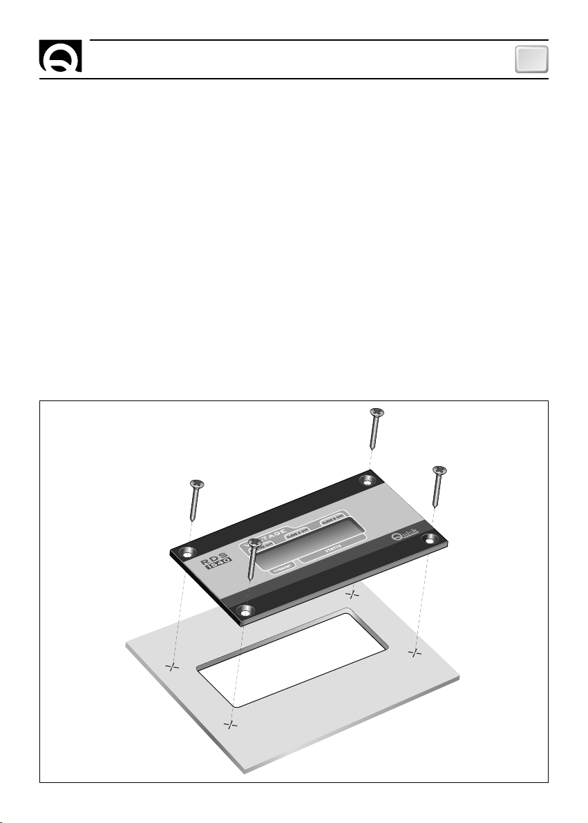
INSTALLAZIONE A PANNELLO
Dopo aver scelto dove posizionare lo strumento, procedere come riportato di seguito:
• Posizionare la dima di foratura (fornita in dotazione) sulla superficie dove sarà installato lo strumento.
• Marcare il centro di ogni foro.
• Realizzare l'asola per il passaggio della parte posteriore dello strumento.
• Rimuovere la dima ed eventuali bave presenti sui fori.
• Inserire lo strumento nella sede.
• Fissare lo strumento al pannello avvitando le viti (non in dotazione).
RDS 1540 - REV003A
5
Page 6
IT
FUNZIONAMENTO
COLLEGAMENTO ELETTRICO
Lo strumento risponde agli standard EMC (compatibilità elettromagnetica) ma è richiesta una corretta installazione per non compromettere le proprie prestazioni e quelle degli strumenti posti nelle vicinanze.
Per questo motivo i cavi dello strumento devono essere distanti almeno:
• 1 m dai cavi che trasportano segnale radio (escluso di radiotrasmittenti SSB).
• 2 m dai cavi che trasportano segnale radio di radiotrasmittenti SSB.
Seguire le regole riportate di seguito per la realizzazione dell'impianto elettrico relativo allo strumento:
• Alimentare lo strumento solo dopo aver effettuato e verificato l'esattezza di tutti i collegamenti elettrici.
• Inserire un interruttore per accendere e spegnere l'apparecchio.
• Inserire un fusibile rapido da 200 mA sulla linea di alimentazione dello strumento.
• Utilizzare come collegamento dell'interfaccia dati (segnali CANH e CANL) un cavo non schermato con
una coppia intrecciata (sezione 0.25/ 0.35 mm
• La lunghezza massima totale del cavo dati deve essere non superiore a 100 metri.
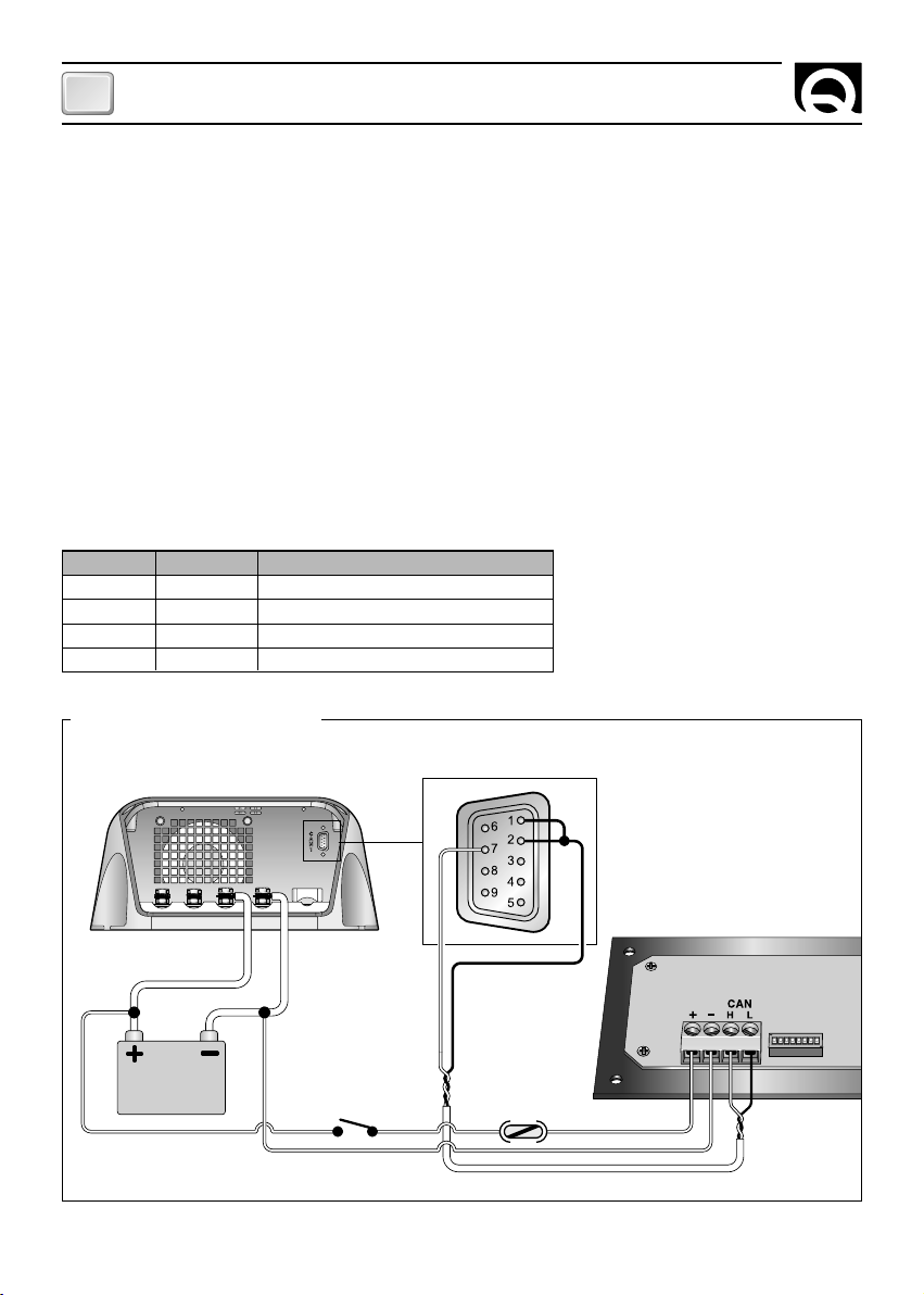
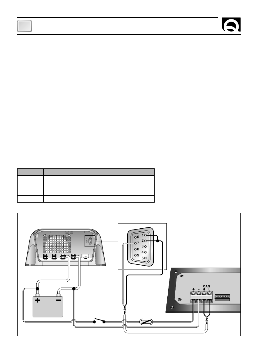
Sul retro dello strumento è presente una morsettiera per i vari collegamenti dei segnali elettrici:
2
AWG 22/24, impedenza 100/150 ohm).
POSIZIONE
1
2
3
4
SEGNALE
+
-
CANH
CANL
SCHEMA DI COLLEGAMENTO
FIG. 1
SBC ADV PLUS
BATTERIA
12V / 24V
DESCRIZIONE
Positivo alimentazione strumento
Negativo alimentazione strumento
Interfaccia CAN
Interfaccia CAN
INTERRUTTORE FUSIBILE
CONNETTORE
A VASCHETTA
A 9 POLI DB9
RDS 1540
1234
ON
1234567 8
6
RDS 1540 - REV003A
Page 7
FUNZIONAMENTO
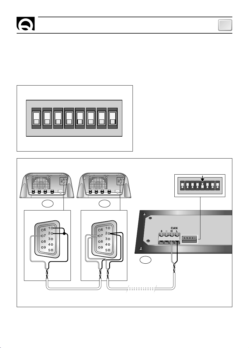
ATTIVAZIONE DEI TERMINATORI
Attivare la terminazione sul primo e sull'ultimo dispositivo collegato alla rete.
Per attivare la terminazione sullo strumento, vedere fig. 2, e paragrafo CONFIGURAZIONE DELLO STRUMENTO.
Di seguito si riporta un esempio di collegamento della rete:
FIG. 2
ON
1234 7856
DIP-SWITCH
IT
SBC ADV PLUS SBC ADV PLUS
21
DB9 TERMINAZIONE ATTIVA DB9
DIP-SWITCH
20
DISPOSITIVI CAN
DA 3 A 19
1234
1234
TERMINAZIONE
ATTIVA
ON
1234567 8
ON
ON
1234567 8
1234567 8
RDS 1540
RDS 1540 - REV003A
7
Page 8
IT
FUNZIONAMENTO
CONFIGURAZIONE DELLO STRUMENTO
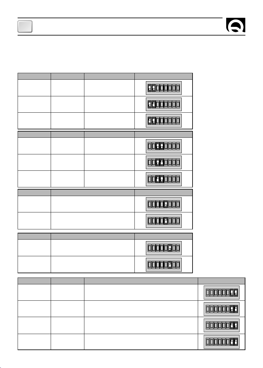
L'impostazione dello strumento avviene tramite un dip-switch. Per configurare il gruppo, la priorità del
caricabatteria di cui si vogliono visualizzare le informazioni e la terminazione CAN, riferirsi alla tabella che viene
riportata di seguito:
SWITCH 1
OFF
OFF
ON
SWITCH 3
OFF
OFF
ON
SWITCH 5
OFF
ON
SWITCH 6
OFF
ON
SWITCH 2
OFF
ON
OFF
SWITCH 4
OFF
ON
OFF
FUNZIONE DESCRIZIONE
TERMINATORE CAN DISATTIVATO
TERMINATORE CAN ATTIVATO
FUNZIONE DESCRIZIONE
Intensità retro-illuminazione BASSA
Intensità retro-illuminazione ALTA
FUNZIONE DESCRIZIONE
GRUPPO
GRUPPO
GRUPPO
PRIORITÀ
PRIORITÀ
PRIORITÀ
A
B
C
FUNZIONE DESCRIZIONE
1
2
3
ON
1234 7856
ON
1234 7856
ON
1234 7856
ON
1234 7856
ON
1234 7856
ON
1234 7856
ON
1234 785 6
ON
1234 785 6
ON
1234 785 6
ON
1234 785 6
SWITCH 7
8
OFF
OFF
ON
ON
SWITCH 8
OFF
ON
OFF
ON
FUNZIONE DESCRIZIONE
Visualizzazione tensione MASTER
Visualizzazione tensione MASTER, SLAVE A
Visualizzazione tensione MASTER, SLAVE B
ON
1234 7856
ON
1234 7856
ON
1234 7856
ON
Visualizzazione tensione MASTER, SLAVE A / B
1234 7856
RDS 1540 - REV003A
Page 9
FUNZIONAMENTO
Gruppo
:
IMPOSTAZIONE DI FABBRICA:
Priorità
Terminatore CAN
Intensità retro-illuminazione
visualizzazione tensione
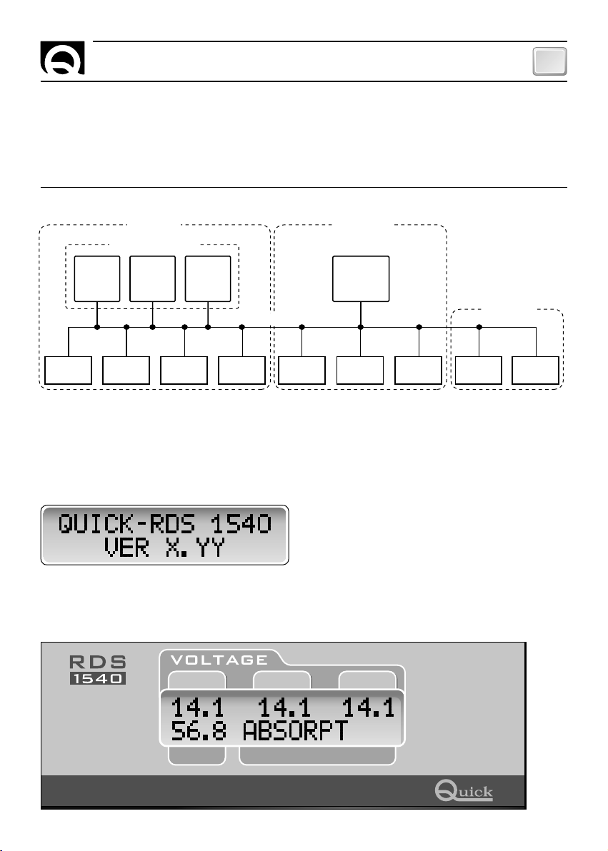
Di seguito viene riportato un possibile schema di una rete di comunicazione CAN:
GRUPPO A GRUPPO B
UNITÀ IN PARALLELO
SBC 1950
ADVANCED
PLUS
(Priorità 1)
SBC 1950
ADVANCED
PLUS
(Priorità 2)
SBC 1950
ADVANCED
PLUS
(Priorità 3)
A
:
1
RETE CAN
:
DISATTIVATO
:
MASTER
SBC 1100
ADVANCED
(Priorità 1)
:
BASSA
PLUS
IT
GRUPPO U
RDS 1540 KTB4 RCM1620 RDS1520 RCM1620 RDS1540
RDS1520
INTERFACCIA
GSM
TERMINALE
LCD
Per la configurazione di rete del caricabatteria, riferirsi al manuale d'uso del caricabatteria collegato.
FUNZIONAMENTO DELLO STRUMENTO
Prima di alimentare lo strumento assicurarsi che la configurazione del dip-switch sia corretta.
Dopo aver collegato l'alimentazione allo strumento, il display visualizzerà per 2 secondi la seguente finestra:
Dove X.YY è la versione corrente del software.
Trascorsi 2 secondi, lo strumento visualizzerà le informazioni riguardanti il carica batteria.
Esempio con SBC 700 ADV PLUS:
SLAVE A OUTMASTER OUT SLAVE B OUT
CURRENT STATUS
RDS 1540 - REV003A
9
Page 10
IT
SEGNALAZIONI
CAMPO
MASTER OUT
SLAVE A OUT
SLAVE B OUT
CURRENT
STATUS
DESCRIZIONE
Tensione uscita Master.
Tensione uscita Slave A.
Tensione uscita Slave B.
Corrente totale erogata dal carica batteria.
Stato del carica batteria.
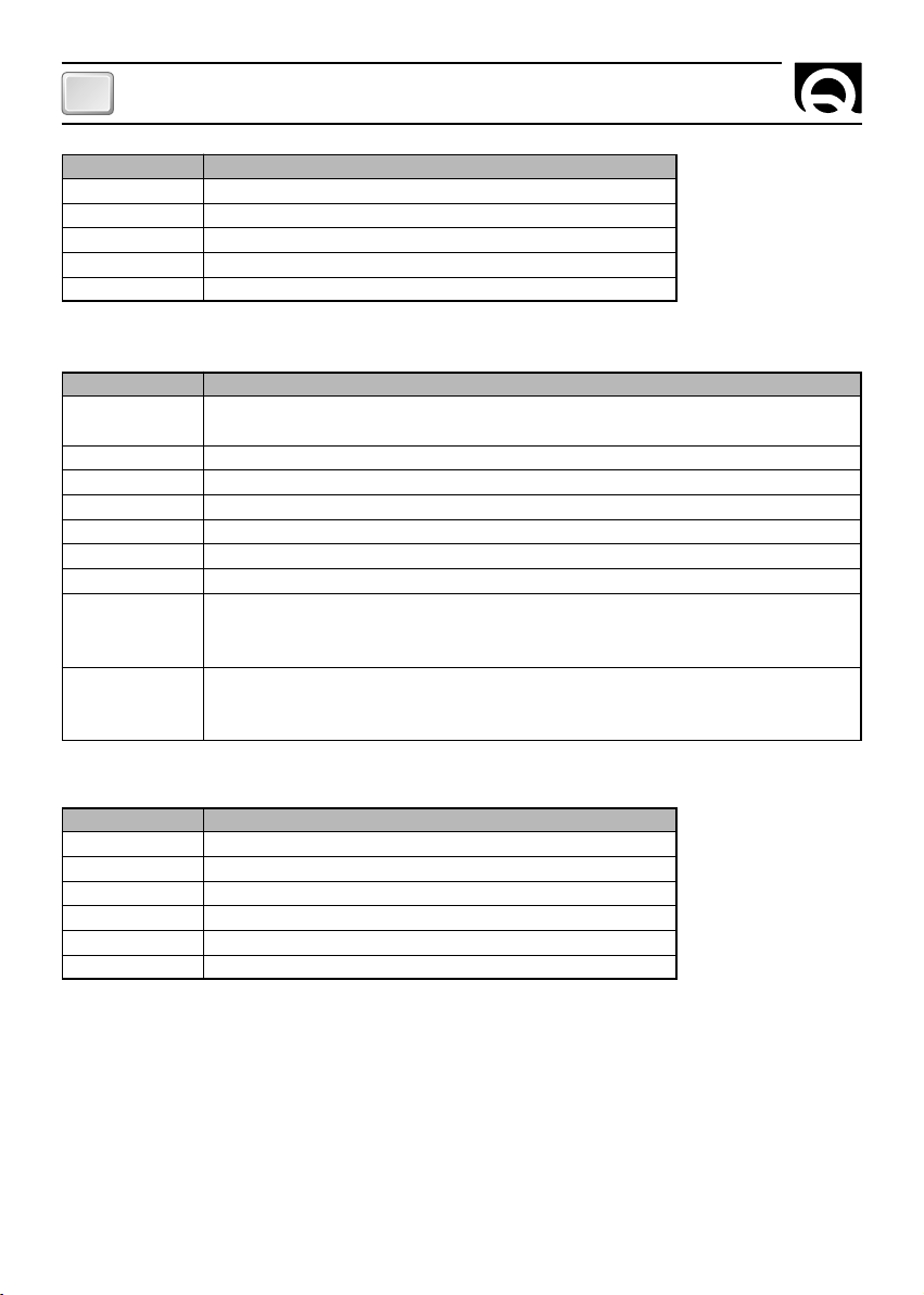
Nel campo STATUS possono essere visualizzati i messaggi riportati nella seguente tabella:
MESSAGGI
INTIT CHECK
FLOAT *
ABSORPT *
BULK *
MONITOR
STANDBY
PROGRAM
NO LINK
ERROR E#
DESCRIZIONE
Il carica batteria sta effettuando un controllo dopo l'uscita dallo stato di Stand-By e dopo l'uscita dalla
programmazione.
Il carica batteria è in stato di FLOAT (vedi tabella seguente).
Il carica batteria è in stato di ABSORPTION (vedi tabella seguente).
Il carica batteria è in stato di BULK (vedi tabella seguente)
Il carica batteria è in stato di Monitor.
Il carica batteria è in stato di Stand-By.
L'utente è entrato nella programmazione del carica batteria.
Collegamento non presente. Se il carica batteria è spento, questa segnalazione è corretta.
Se il carica batteria è acceso, provare a spegnere e riaccendere lo strumento, verificare il collegamento
del cavo di trasmissione dati, la configurazione del gruppo, la priorità e la terminazione CAN.
Il carica batteria è in stato di errore.
Al posto del carattere # è visualizzato il numero relativo al codice di errore del carica batteria (numeri
comprei tra 1 e 9, riferirsi al manuale d'uso del carica batteria).
Al posto del carattere * possono essere visualizzati i messaggi riportati nella seguente tabella:
*
U
L
F
C
H
S
DESCRIZIONE
Bassa tensione di rete AC.
Limitazione di potenza.
Temperatura batterie non corretta.
Problema di comunicazione su CAN BUS.
Modalità di metà potenza.
Controllo digitale unità in parallelo attivo.
Per ulteriori dettagli, riferirsi al manuale d'uso del carica batteria di cui lo strumento visualizza le informazioni.
10
RDS 1540 - REV003A
Page 11
SEGNALAZIONI - DATI TECNICI
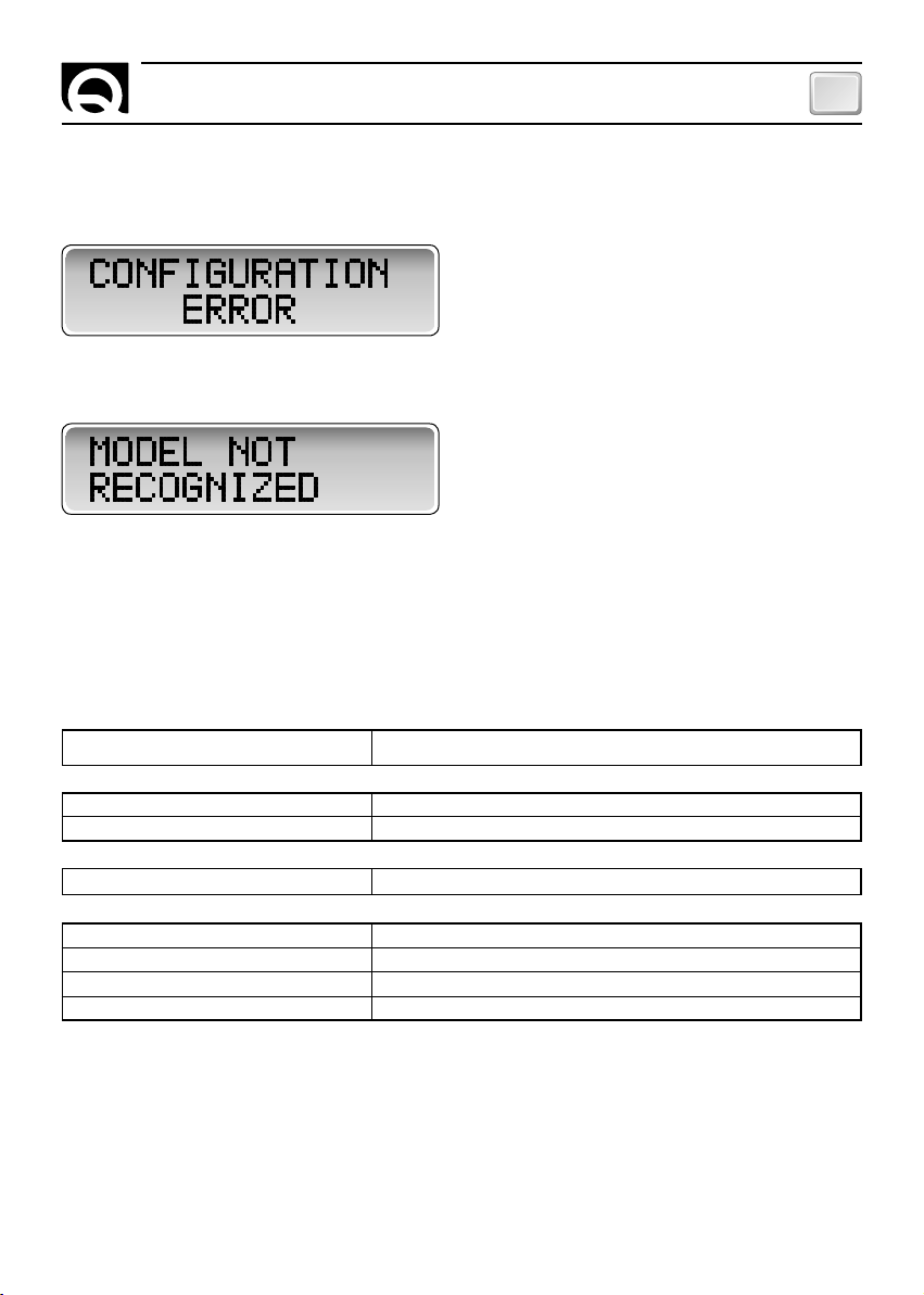
PROBLEMI
• Nel caso in cui il dip-switch sia impostato in maniera errata, comparirà la seguente segnalazione:
• Nel caso in cui lo strumento non riconosca il carica batteria collegato, comparirà la seguente finestra:
Accertarsi che il carica batteria sia della serie SBC ADV PLUS.
CARATTERISTICHE TECNICHE
IT
MODELLO
RDS 1540
CARATTERISTICHE DI INGRESSO
Tensione di alimentazione
Assorbimento massimo
(1)
(2)
da 8 a 30 Vdc
120 mA
CARATTERISTICHE AMBIENTALI
Temperatura operativa
(3)
da -20 a + 70° C
GENERALI
Dimensioni (L x A x P)
Peso
Interfaccia di comunicazione
Classe EMC
(1)
Lo strumento può resettarsi con una tensione di alimentazione inferiore agli 8 Vdc.
(2)
Valore tipico con retro-illuminazione attiva ad intensità alta.
(3)
Con temperature inferiori a 0°C i cristalli del display rallentano il loro movimento.
QUICK® SI RISERVA IL DIRITTO DI APPORTARE MODIFICHE ALLE CARATTERISTICHE TECNICHE DELL'APPARECCHIO E AL CONTENUTO DI QUESTO MANUALE SENZA ALCUN PREAVVISO.
RDS 1540 - REV003A
EN 61326-1 - EN 55011-B - FCC part 15 rules 47
120 mm x 65 mm x 34 mm
140 g
CAN BUS con transceiver differenziale
11
Page 12

GB
CHARACTERISTICS AND INSTALLATION
RDS 1540
The RDS 1540 remote display allows status of the SBC ADV PLUS medium and high power battery chargers to be
monitored through the CAN BUS interface.
Other important advantages which the RDS 1540 offer, are:
• Alphanumeric LCD display.
• Option of choosing whether to display one, two, or all three output voltages from the battery charger.
• Display of the total current supplied by the battery charger.
• Backlight display screen with 2 brightness levels.
• Automatic display contrast compensation according to environmental temperature.
• Universal power supply (12/24Vdc).
• CAN BUS interface for data transfer.
• Easy installation.
• Can work in a wide range of ambient temperatures.
INSTALLATION
BEFORE USING THE INSTRUMENT CAREFULLY READ THIS USER’S MANUAL. IN CASE OF DOUBT
CONTACT THE “QUICK
In case of discordance or errors in translation between the translated version and the original text in the
F
Italian language, reference will be made to the Italian or English text.
This device was designed and constructed for use on recreational crafts.
F
Other forms of use are not permitted without written authorization from the company Quick
The Quick
Manual. Quick® shall not be held responsible for any direct or indirect property damage or personal injury
caused by inappropriate or unintended use of the equipment, erroneous installation or any errors that may be
present in this manual.
®
RDS 1540 remote display has been designed for the purposes and tasks outlined in this User's
®
” SUPPLIER OR AFTER SALES SERVICE DEPARTMENT.
®
.
THE WARRANTY SHALL BE VOID IF THE INSTRUMENT IS TAMPERED WITH OR ALTERED BY NON
AUTHORISED PERSONNEL.
THE PACKAGE CONTAINS:
RDS 1540 - drilling template - connecting cable - user's manual - conditions of warranty.
INSTALLING THE INSTRUMENT
The typical installation procedure is described herein. Needless to say, it is not possible to describe a procedure
applicable for all situations that may be encountered.
Adapt this procedure to satisfy your own personal requirements.
Locate the most suitable position to house the instrument following the recommendations given below:
• The instrument should be installed in a place where it can be easily read by the operator.
• Select a clean, smooth and flat area.
• Access from the rear must be available for installation and maintenance purposes.
• Leave enough space free behind the installation to conveniently fit the back of the instrument and the
connectors.
• The back of the instrument must be protected against contact with water and moisture.
• Pay careful attention when drilling the panel or parts of the boat. This hole should not weaken or
break/crack the boat's structure.
12
RDS 1540 - REV003A
Page 13
INSTALLATION
The instrument meets EMC standards (electromagnetic compatibility) however correct installation is fundamental in order not to compromise its performance as well as operation of the instruments found nearby.
For this reason, the instrument should be at least:
• 25 cm away from the compass.
• 50 cm away from any radio receivers.
• 1 m away from any radio transmitters (except for SSB).
• 2 m away from any SSB radio transmitters.
• 2 m away from radar beams.
GB
PANEL INSTALLATION
After selecting the area where the instrument is to be installed, perform the steps given below:
• Place the drilling template (supplied) on the surface where the instrument will be installed.
• Mark the center of each hole.
• Create the slot for the passage of the rear part of the instrument.
• Remove the template and any burrs present in the hole.
• Put the instrument in place.
• Fix the instrument to the panel with the screws (not included in the equipment).
RDS 1540 - REV003A
13
Page 14
GB
OPERATING
ELECTRIC CONNECTIONS
The instrument meets EMC standards (electromagnetic compatibility) however correct installation is fundamental in order not to compromise its performance as well as operation of the instruments found nearby. For this
reason, the instrument's cables must be at least:
• 1 m away from cables that carry radio signals (except for SSB radio transmitters).
• 2 m away from cables that carry SSB radio transmitter radio signals.
Follow the rules given below when doing the electrical work for the instrument:
• Turn on power to the instrument only after making and checking that all the electric connections are correct.
• Put in a switch to turn on and shut off the instrument.
• Install a 200 mA fast blow fuse on the instrument's power supply line.
2
• Use an unscreened cable with a braided pair (cross section 0.25/ 0.35 mm
AWG 22/24, impedance 100/150
ohm) for data interface connection (CANH and CANL signals).
• The data cable cannot be more than 100 meters long.
A terminal block is found at the back of the instrument for connection of the various electric signals.
POSITION
1
2
3
4
SIGNAL
+
-
CANH
CANL
CONNECTION DIAGRAM
FIG. 1
SBC ADV PLUS
BATTERY
12V / 24V
DESCRIPION
Instrument positive power supply
Instrument negative power supply
CAN interface
CAN interface
SWITCH FUSE
FEMALE
CONNECTOR
A 9 POLI DB9
RDS 1540
1234
ON
1234567 8
14
RDS 1540 - REV003A
Page 15

OPERATING
GB
ACTIVATING THE TERMINATORS
Activate the termination at the first and last device connected to the network. To activate the termination, see
fig. 2 and paragraph SETTING UP THE INSTRUMENT.
An example showing network connection is given below:
FIG. 2
ON
1234 7856
DIP-SWITCH
SBC ADV PLUS SBC ADV PLUS
21
DB9 TERMINATION ACTIVED DB9
DIP-SWITCH
20
CAN DEVICES
DA 3 A 19
1234
1234
TERMINATION
ACTIVED
ON
1234567 8
ON
ON
1234567 8
1234567 8
RDS 1540
RDS 1540 - REV003A
15
Page 16

GB
OPERATING
SETTING UP THE INSTRUMENT
The instrument is set up using a dip-switch. To configure the unit, priority of the battery charger which the information is shown for and CAN termination, refer to the table given below:
SWITCH 1
OFF
OFF
ON
SWITCH 3
OFF
OFF
ON
SWITCH 5
OFF
ON
SWITCH 6
OFF
ON
SWITCH 2
OFF
ON
OFF
SWITCH 4
OFF
ON
OFF
FUNCTION DESCRIPTION
CAN TERMINATOR DEACTIVATED
CAN TERMINATOR ACTIVATED
FUNCTION DESCRIPTION
Backlighting intensity LOW
Backlighting intensity HIGH
FUNCTION DESCRIPTION
GROUP
A
GROUP
B
GROUP
C
FUNCTION DESCRIPTION
PRIORITY
PRIORITY
PRIORITY
1
2
3
ON
1234 7856
ON
1234 7856
ON
1234 7856
ON
1234 7856
ON
1234 7856
ON
1234 7856
ON
1234 785 6
ON
1234 785 6
ON
1234 785 6
ON
1234 785 6
SWITCH 7
16
OFF
OFF
ON
ON
SWITCH 8
OFF
ON
OFF
ON
FUNCTION
Voltage display MASTER
Voltage display MASTER, SLAVE A
Voltage display MASTER, SLAVE B
Voltage display MASTER, SLAVE A / B
DESCRIPTION
ON
1234 7856
ON
1234 7856
ON
1234 7856
ON
1234 7856
RDS 1540 - REV003A
Page 17

FACTORY SETTING:
Group
Priority
CAN Termination
Backlighting intensity
Voltage display
A possible CAN network is illustrated below:
GROUP A GROUP B
UNITS IN PARALLEL
SBC 1950
ADVANCED
PLUS
(Priority 1)
SBC 1950
ADVANCED
PLUS
(Priority 2)
SBC 1950
ADVANCED
PLUS
(Priority 3)
CAN NETWORK
:
A
:
1
: DEACTIVATED
: LOW
: MASTER
SBC 1100
ADVANCED
PLUS
(Priority 1)
OPERATING
GROUP U
GB
RDS 1540 KTB4 RCM1620 RDS1520 RCM1620 RDS1540
RDS1520
GSM
INTERFACE
LCD
TERMINAL
For more information about battery charger configuration, consult the User's manual for the battery charger
used.
INSTRUMENT OPERATION
Before attempting to turn on the instrument, make certain the dip - switch is set to the correct position. After
hooking up the instrument to the power supply, the display shows the following window for 2 seconds.
When X.YY is the current version of the software.
After 2 seconds the instrument displays the battery charge information.
Example with SBC 700 ADV PLUS.
SLAVE A OUTMASTER OUT SLAVE B OUT
CURRENT STATUS
RDS 1540 - REV003A
17
Page 18

GB
NOTIFICATION SIGNS
FIELD
MASTER OUT
SLAVE A OUT
SLAVE B OUT
CURRENT
STATUS
DESCRIPTION
MASTER output voltage.
Slave A output voltage.
Slave B output voltage.
Total current delivered by the battery charger.
Battery charger status.
The STATUS field can display the messages shown in the following table:
MESSAGES
INTIT CHECK
FLOAT *
ABSORPT *
BULK *
MONITOR
STANDBY
PROGRAM
NO LINK
ERROR E#
DESCRIPTION
The battery charger is running a check after leaving STAND-BY status and after leaving
programming.
The battery charger is in FLOAT status (see the table below).
The battery charger is in ABSORPTION status (see the table below).
The battery charger is in BULK status (see the table below).
The battery charger is in MONITOR status.
The battery charger is in Stand-by status.
The user has entered battery charger programming.
Connection not present. If the battery charger is switched off, this is the correct signal to see.
If the battery charger is switched on, try switching the instrument off and on, check the connection of
the data transmission cable, the unit's configuration, and the CAN priority and termination.
The battery charger is in error status. In the place of the character #, the battery charger's
respective error code number appears (numbers in a range of 1 - 9; consult the battery charger's
operation manual).
In the place of the character *, the messages displayed in the following table can appear:
*
U
L
F
C
H
S
DESCRIPTION
AC voltage low.
Power limitation.
Incorrect battery temperature.
Communication problem on the CAN BUS.
Half power mode.
Digital control of the parallel units on.
For more details, refer to the manual of use of the battery charger for which the instrument displays information.
18
RDS 1540 - REV003A
Page 19

NOTIFICATION SIGNS - TECHNICAL DATA
PROBLEMS
• If the dip-switch is set wrong the following message appears.
• If the instrument fails to recognise the attached battery charger the following window appears.
Check that the battery charger is from the SBC ADV PLUS series.
TECHNICAL DATA
GB
MODEL RDS 1540
INPUT CHARACTERISTICS
Supply voltage
Maximum absorption
AMBIENT CHARACTERISTICS
Operating temperature
GENERAL
Dimensions (W x H x D)
Weight
Communication interface
EMC class
(1)
The instrument can reset itself at a voltage less than 8 Vdc.
(2)
Typical value with backlighting on at high intensity.
(3)
At temperatures below 0°C the movement of the display crystals slows down.
QUICK® RESERVES THE RIGHT TO MODIFY THE TECHNICAL CHARACTERISTICS OF THE EQUIPMENT AND THE CONTENTS OF THIS MANUAL WITHOUT PRIOR NOTICE.
RDS 1540 - REV003A
(1)
(2)
(3)
EN 61326-1 - EN 55011-B - FCC part 15 rules 47
from 8 to 30 Vdc
120 mA
from -20 to + 70° C
120 mm x 65 mm x 34 mm
140 g
CAN BUS with differential transceiver
19
Page 20

FR
CARACTERISTIQUES ET INSTALLATION
RDS 1540
Le tableau déporté RDS 1540 est un instrument qui permet de contrôler l'état de charge de batterie SBC ADV
PLUS medium et high power, par l'intermédiaire de l'interface CAN BUS.
Autres avantages du RDS 1540 sont:
• Ecran LCD alphanumérique.
• Possibilité de choisir d'afficher une, deux ou les trois tensions de sortie du chargeur de batteries.
• Affichage du courant total distribué par le chargeur de batteries.
• Intensité réglable du rétro éclairage de l'afficheur.
• Compensation automatique du contraste de l'afficheur selon la température ambiante.
• Alimentation électrique universelle (12/24Vdc)
• Interface CAN BUS pour le transfert de données.
• Facilité d'installation.
• Fonctionnement dans une large gamme de temperature.
INSTALLATION
AVANT D'UTILISER L'INSTRUMENT, LIRE ATTENTIVEMENT CE LIVRET D'UTILISATION. EN CAS DE
DOUTE, CONTACTER LE REVENDEUR OU LE SERVICE APRES VENTE CLIENTS QUICK®.
En cas de discordances ou d’erreurs éventuelles entre la traduction et le texte original en italien, se référer
F
au texte italien ou anglais.
Ce dispositif a été conçu et réalisé pour être utilisé sur des bateaux de plaisance.
F
Tout autre emploi est interdit sans autorisation écrite de la société Quick
®
Le tableau à distance RDS 1540 Quick
société Quick® ne peut être tenue responsable des dommages directs ou indirects causés par une utilisation
impropre de l'appareil, par une mauvaise installation ou par de possible erreurs présentes dans ce livret.
a été conçu pour les utilisations décrites dans ce livret d'utilisation. La
L'ENDOMMAGEMENT DE L'INSTRUMENT PAR UN PERSONNEL NON AUTORISE ENTRAINE
L'ANNULATION DE LA GARANTIE.
L'EMBALLAGE CONTIENT LES ÉLÉMENTS SUIVANTS:
ment - conditions de garantie - manuel de l'utilisateur.
RDS 1540 - gabarit de perçage - câble de branche-
INSTALLATION DE L'INSTRUMENT
Ci-dessous nous avons décrit une procédure d'installation typique. Il est impossible de décrire une procédure
qui soit applicable à toutes les situations. Adapter cette procédure afin de répondre à vos exigences propres.
Trouver la position la plus adaptée pour réaliser les logements qui vont recevoir l'instrument en suivant les critères suivants:
• L'instrument doit être placé de manière à ce qu'il puisse être lu facilement par l'opérateur.
• Choisir un emplacement qui est propre, lisse et plan.
• Il doit y avoir un accès par l'arrière pour faciliter l'installation et l'entretien.
• Il doit y avoir un espace suffisant derrière la position choisie pour placer le dos de l'instrument et les
connecteurs.
• La partie arrière de l'instrument doit être protégée contre tout contact avec l'eau ou l'humidité.
• Faire particulièrement attention quand vous réalisez les orifices sur les panneaux ou sur certaines
parties de l'embarcation.
Ces orifices ne doivent pas fragiliser ou causer la rupture de la structure de l'embarcation.
®
.
20
RDS 1540 - REV003A
Page 21

INSTALLATION
L'instrument répond aux standards EMC (compatibilité électromagnétique) mais il est nécessaire de procéder
à une installation correcte afin de ne pas compromettre ses propres prestations et celles des instruments qui
sont placés à côté.
Pour cette raison l'instrument doit être éloigné d'au moins:
• 25 cm du compas.
• 50 cm d'un appareil radio récepteur quelconque.
• 1 m d'un appareil radio transmetteur quelconque (sauf SSB).
• 2 m d'un appareil radio transmetteur quelconque SSB.
• 2 m des faisceaux radar.
FR
INSTALLATION SUR PANNEAU
Après avoir choisi l'emplacement de l'instrument, procéder comme reporté ci-dessous:
• Placer le gabarit de perçage (fourni avec l'équipement) sur la surface où sera installé l'instrument.
• Marquer le centre de chaque orifice.
• Réaliser découpe pour le passage de la partie arrière de l'instrument.
• Retirer le gabarit et les éventuelles ébarbures présentes sur les orifices.
• Introduire l'instrument dans son logement.
• Fixer l'instrument au panneau a l'aide des vis (non fournies avec l'appareil).
RDS 1540 - REV003A
21
Page 22

FR
FONCTIONNEMENT
BRANCHEMENT ELECTRIQUE
L'instrument répond aux standards EMC (compatibilité électromagnétique) mais il est nécessaire de procéder
à une installation correcte afin de ne pas compromettre ses propres prestations et celles des instruments qui
sont placés à côté.
Pour cette raison l'instrument doit être éloigné d'au moins:
• 1 m des câbles qui transportent un signal radio (sauf émetteurs BLU).
• 2 m des câbles qui transportent le signal radio de radio d'émetteurs BLU.
Suivre les règles reportées ci-dessous pour la réalisation de l'installation électrique relative à l'instrument:
• N'alimenter l'instrument qu'après avoir effectué et vérifié que tous les branchements électriques sont
corrects.
• Introduire un interrupteur pour allumer et éteindre l'appareil.
• Introduire un fusible rapide de 200 mA sur la ligne d'alimentation de l'instrument.
• Utiliser comme connexion de l'interface données (signaux CANH et CANL) un câble non blindé avec un couple
tressé (section 0.25/ 0.35 mm
• La longueur maximale totale du câble données doit être inférieure à 100 mètres.
Au dos de l'instrument se trouve un bornier pour les divers branchements des signaux électriques:
2
AWG 22/24, impédance 100/150 ohm).
POSITION
1
2
3
4
SIGNAL
+
-
CANH
CANL
DESCRIPTION
Positif alimentation instrument
Négatif alimentation instrument
Interface CAN
Interface CAN
SCHÉMA DE CONNEXION
FIG. 1
SBC ADV PLUS
BATTERIE
12V / 24V
INTERRUPTEUR FUSIBLE
CONNECTEUR
BROCHE
À 9 PINS DB9
RDS 1540
1234
ON
1234567 8
22
RDS 1540 - REV003A
Page 23

FONCTIONNEMENT
ACTIVATION DES TERMINAUX
Activer la terminaison sur le premier et sur le dernier dispositif relié au réseau.
Pour activer la terminaison sur l'instrument, voir fig. 2, et paragraphe CONFIGURATION DE L'INSTRUMENT.
Nous avons reporté ci-dessous un exemple de branchement du réseau:
FIG. 2
ON
1234 7856
DIP-SWITCH
FR
SBC ADV PLUS SBC ADV PLUS
21
DB9 TERMINAZIONE ATTIVA DB9
DIP-SWITCH
20
DISPOSITIFS CAN
DA 3 A 19
1234
1234
TERMINAISON
ACTIVÉE
ON
1234567 8
ON
ON
1234567 8
1234567 8
RDS 1540
RDS 1540 - REV003A
23
Page 24

FR
ON ONN N
CONFIGURATION DE L'INSTRUMENT
Le paramétrage de l'instrument se fait au moyen d'un dip-switch. Pour configurer le groupe, la priorité du chargeur de batteries dont on veut afficher les informations et la terminaison CAN, faire référence au tableau reporté
ci-dessous:
SWITCH 1
OFF
OFF
ON
3
O
O
ON
5
O
ON
6
O
ON
SWITCH 2
OFF
ON
OFF
4
O
ON
O
ON ON ON
TERMINAL CAN DÉSACTIVÉ
TERMINAL CAN ACTIVÉ
ON ON ON
Intensité BASSE de rétro-illumination
Intensité
ÉLEVÉE de rétro-illumination
FONCTION DESCRIPTION
GROUPE
GROUPE
GROUPE
PRIORITÉ
PRIORITÉ
PRIORITÉ
A
B
C
ON ON ON
1
2
3
ON
1234 7856
ON
1234 7856
ON
1234 7856
ON
1234 7856
ON
1234 7856
ON
1234 7856
ON
1234 785 6
ON
1234 785 6
ON
1234 785 6
ON
1234 785 6
24
O
O
ON
ON
7
8
O
ON
O
ON
ON ON
Affichage tension MASTER
Affichage tension MASTER, SLAVE A
Affichage tension MASTER, SLAVE B
Affichage tension MASTER, SLAVE A / B
ON
ON
1234 7856
ON
1234 7856
ON
1234 7856
ON
1234 7856
RDS 1540 - REV003A
Page 25

FONCTIONNEMENT
Groupe
:
A
PARAMÉTRAGE D'USINE :
Priorité
Terminal CAN désactivé
Intensité de rétro-illumination
Affichage tension
Nous avons reporté ci-dessous le schéma d'un réseau de communication CAN possible:
GROUPE A GROUPE B
UNITÉ EN PARALLÉLE
SBC 1950
ADVANCED
PLUS
(Priorité 1)
SBC 1950
ADVANCED
PLUS
(Priorité 2)
SBC 1950
ADVANCED
PLUS
(Priorité 3)
:
1
RETE CAN
: DÉSACTIVÉ
: MASTER
SBC 1100
ADVANCED
(Priorité 1)
: BASSE
PLUS
GROUPE U
FR
RDS 1540 KTB4 RCM1620 RDS1520 RCM1620 RDS1540
RDS1520
INTERFACE
GSM
TERMINAL
LCD
Pour la configuration du chargeur de batteries, se référer au livret d'utilisation du chargeur de batteries qui y est
relié.
FONCTIONNEMENT DE L'INSTRUMENT
Avant d'alimenter l'instrument, s'assurer que la configuration du dip - switch est correcte.
Après avoir branché l'alimentation à l'instrument, l'écran affichera la fenêtre suivante pendant 2 secondes:
Où X.YY est la version courante du software.
Après 2 secondes, l'instrument affichera les informations concernant le chargeur de batteries.
Exemple avec SBC 700 ADV PLUS:
SLAVE A OUTMASTER OUT SLAVE B OUT
CURRENT STATUS
RDS 1540 - REV003A
25
Page 26

FR
SIGNALISATIONS
CHAMP
MASTER OUT
SLAVE A OUT
SLAVE B OUT
CURRENT
STATUS
DESCRIPTION
Tension sortie MASTER .
Tension sortie Slave A.
Tension sortie Slave B.
Courant total distribué par le chargeur de batteries.
Etat du chargeur de batteries.
Dans le champ STATUS, les messages indiqués dans le tableau suivant peuvent être affichés:
MESSAGES
INTIT CHECK
FLOAT *
ABSORPT *
BULK *
MONITOR
STANDBY
PROGRAM
NO LINK
ERROR E#
DESCRIPTION
Le chargeur de batteries est en train d'effectuer un contrôle après la sortie du STAND-BY et
après la sortie de la programmation
Le chargeur de batteries est en FLOAT (voir tableau suivant).
Le chargeur de batteries est en ABSORPTION (voir tableau suivant).
Le chargeur de batteries est en BULK (voir tableau suivant).
Le chargeur de batteries est en Monitor.
Le chargeur de batteries est en Stand-By.
L'utilisateur est entré dans la programmation du chargeur de batteries .
Absence de branchement. Si le chargeur de batteries est éteint, cette indication est correcte.
Si le chargeur de batteries est allumé, essayer d’éteindre et de rallumer l’instrument, vérifier le
branchement du câble de transmission des données, la configuration du groupe, la priorité et la
terminaison CAN.
Le chargeur de batteries est en erreur. A la place du caractère #, le chiffre relatif au code
d'erreur du chargeur de batteries est affiché (chiffres allant de 1 à 9, se référer au manuel du chargeur
de batteries).
A la place du caractère * les messages indiqués dans le tableau suivant peuvent être affichés:
*
U
L
F
C
H
S
DESCRIPTION
Tension de secteur AC basse.
Limitation de puissance.
Température des batteries incorrecte.
Problème de communication sur CAN BUS.
Modalité de puissance moyenne.
Contrôle digital unité en parallèle, activé.
Pour d'autres détails, se référer au manuel d'utilisation du chargeur de batteries dont l'instrument affiche les
informations.
26
RDS 1540 - REV003A
Page 27

SIGNALISATIONS
- CARACTÉRISTIQUES TECH.
PROBLÈME
• Si le dip-switch était réglé de manière erronée, l'indication suivante apparaîtra.
• Si l'instrument ne reconnaissait pas le chargeur de batteries qui est connecté, la fenêtre suivante
apparaîtra.
S'assurer que le chargeur de batterie soit de la série SBC ADV PLUS.
CARACTÉRISTIQUES TECHNIQUES
FR
MODÈLE
RDS 1540
CARACTERISTIQUES D'ENTREE
Tension d'alimentation
Consommation maximale
(1)
(2)
de 8 à 30 Vdc
120 mA
CARACTERISTIQUES AMBIANTES
Température de fonctionnement
(3)
de -20 à + 70° C
CARACTERISTIQUES GENERALES
Dimensions (L x H x P)
Poids
Interface de communication
Classe EMC
(1)
L'instrument peut être restauré avec une tension d'alimentation inférieur aux 8 Vdc.
(2)
Valeur typique avec rétro-illumination active à intensité élevée.
(3)
Avec des températures inférieures à 0°C les mouvements des cristaux de l'écran ralentissent.
LA SOCIETÉ QUICK® SE RÉ SER VE LE DRO IT D'AP POR TER LES MO DI FI CA TIONS NÉ CES SA I RES A UX CA RAC TÉ RIS TI QUES TE CHNI QUES DE L'AP PA RE IL ET AU CON TE NU DE CE LI VRET SANS A VIS PRÉ A LA BLE.
RDS 1540 - REV003A
EN 61326-1 - EN 55011-B - FCC part 15 rules 47
120 mm x 65 mm x 34 mm
140 g
CAN BUS avec transceiver différentiel
27
Page 28

DE
EIGENSCHAFTEN UND INSTALLATION
RDS 1540
Beimm Überwachungspaneel RDS 1540 handelt es sich um ein Gerät zur Überwachung des Zustands der
Batterieladegeräte SBC ADV PLUS "medium" und "high power" anhand der CAN BUS-Schnittstelle.
Die Überwachungspaneel RDS 1540 bieten die folgenden wesentlichen Vorteile:
• Alphanumerische LCD-Display.
• Es kann zwischen der Anzeige von einer, zwei oder allen drei Ausgangsspannungen vom Batterieladegerät
gewählt werden.
• Anzeige vom Gesamtstrom, der vom Batterieladegerät abgegeben worden ist.
• Von hinten beleuchtetes Display, einstellbar auf 2 verschiedene Intensitätsstufen.
• Automatischer Display-Kontrastausgleich in Abhängigkeit von der Raumtemperatur.
• Universalspeisung (12/24Vdc).
• CAN BUS-Schnittstelle zur Datenübertragung.
• Einfache Installation.
• Betrieb innerhalb eines großen Bereichs von Raumtemperaturen nutzbar.
INSTALLATION
VOR INBETRIEBNAHME DES GERÄTES MUSS DIE VORLIEGENDE GEBRAUCHSANLEITUNG
AUFMERKSAM DURCHGELESEN WERDEN. KONTAKTIEREN SIE BITTE IM ZWEIFELSFALL ODER
BEI UNKLARHEITEN IHREN HÄNDLER ODER DEN QUICK
Bei Fehlern oder eventuellen Unstimmigkeiten zwischen der Übersetzung und dem Ausgangstext ist der
F
Ausgangstext in Italienisch oder Englisch maßgeblich.
Diese Vorrichtung wurde für den Einsatz auf Sportbooten entwickelt und realisiert.
F
Ohne schriftliche Zustimmung durch Quick
Das Fernkontroll-Display RDS 1540 Quick
entworfen und hergestellt. Quick
auf einen unsachgemäßen Gebrauch des Gerätes, auf eine falsche Installation oder auf mögliche, in diesem
Handbuch enthaltene Fehler zurückzuführen sind.
®
übernimmt keinerlei Verantwortung für direkte oder indirekte Schäden, die
®
ist keine anderweitige Nutzung zulässig.
®
wurde für die in dieser Gebrauchsanleitung beschriebenen Zwecke
®
-KUNDENDIENST.
DER BETRIEB DES GERÄTES DURCH NICHT AUTORISIERTE PERSONEN FÜHRT ZUM VERFALL DER
GARANTIE.
IM LIEFERUMFANG:
RDS 1540 - Bohrschablone - Anschlusskabel - Betriebsanleitung -
Garantiebedingungen
.
INSTALLATION DES GERÄTES
Im Nachfolgenden wird ein typisches Installationsverfahren beschrieben.
Es ist nicht möglich, ein Verfahren zu beschreiben, dass sich auf alle Situationen anwenden lässt. Dieses
Verfahren muss demnach den jeweiligen persönlichen Bedürfnissen angepasst werden. Es muss ein geeigneter
Montageort gefunden werden. Hierbei die folgenden Kriterien in Betracht ziehen:
• Das Gerät muss so positioniert werden, dass es vom Bediener leicht abgelesen werden kann.
• Eine saubere, glatte und ebene Position auswählen.
• Für die Installation und die Wartung muss ein Zugang von hinten möglich sein.
• Hinter der gewählten Position muss genug Platz vorhanden sein, um die Rückseite des Gerätes und die
Verbinder unterz ubringen.
• Der hintere Teil des Gerätes muss vor Wasser und Feuchtigkeit geschützt werden.
• Bei der Ausführung der Bohrungen an den Tafeln oder an Teilen des Bootes muss äußerst vorsichtig
vorgegangen werden. Besagte Bohrungen dürfen sich keinesfalls auf die Stabilität die Bootkonstruktion
auswirken oder Schäden daran verursachen.
28
RDS 1540 - REV003A
Page 29

INSTALLATION
Das Gerät entspricht den EMV-Standardvorgaben (elektromagnetische Verträglichkeit). Voraussetzung dafür ist
allerdings eine korrekte Installation, um die eigenen Leistungen sowie diejenigen der in der Nähe positionierten
Instrumente nicht zu beeinträchtigen.
Aus diesem Grund muss das Gerät mindestens folgende Abstände zu den anderen Einrichtungen einhalten:
• 25 cm vom Kompass.
• 50 cm von einem beliebigen Funkempfangsgerät.
• 1 m von einem beliebigen Funksendegerät (SSB ausgeschlossen).
• 2 m von einem beliebigen SSB-Funksendegerät.
• 2 m vom Strahlengang des Radarstrahlenbündels.
DE
INSTALLATION AN DER SCHALTTAFEL
Nachdem man die Stelle ausgewählt hat, an der das Gerät positioniert werden soll, wie im folgenden
beschrieben fortfahren:
• Die Bohrschablone (als Ausrüstungszubehörim im Lieferumfang) auf der Oberfläche auflegen, auf der das Gerät
installiert werden soll.
• Die Mitte jedes Lochs markieren.
• Einen Schlitz ausführen, durch den die Rückseite vom Instrument gesteckt wird.
• Die Schablone sowie eventuelle an den Bohrungen vorhandene Grate entfernen.
• Das Gerät einsetzen.
• Das Instrument an der Tafel befestigen und die Schrauben anziehen (nicht mitgelieferten).
RDS 1540 - REV003A
29
Page 30

DE
BETRIEB
STROMANSCHLUSS
Das Überwachungspaneel entspricht den EMV-Standardvorgaben (elektromagnetische Verträglichkeit).
Voraussetzung dafür ist allerdings eine korrekte Installation, um die eigene Leistung sowie die der in der Nähe
positionierten Instrumente nicht zu beeinträchtigen.
Aus diesem Grund müssen die Kabel des Gerätes mindestens folgende Abstände aufweisen:
• 1 m von den Kabeln, die das Funksignal übertragen (ausgenommen SSB- Funksendegerät).
• 2 m von den Kabeln, die das Funksignal von SSB- Funksendegeräten übertragen.
Bei der Ausführung der Stromanlage des Gerätes müssen die nachfolgend beschriebenen Regeln eingehalten
werden:
• Das Gerät erst dann mit Strom versorgen, nachdem man die Richtigkeit aller elektrischen Anschlüsse
überprüft hat.
• Einen Schalter einsetzen, um das Gerät ein- und auszuschalten.
• Eine flinke Sicherung mit 200 mA an der Zuleitung des Gerätes einsetzen.
• Für den Anschluss der Datenschnittstelle (Signale CANH und CANL) ein nicht abgeschirmtes Kabel mit
einem verflochtenen Paar verwenden (Querschnitt 0.25/ 0.35 mm
Impedanz 100/150 Ohm).
• Die maximale Gesamtlänge des Datenkabels darf nicht mehr als 100 Meter betragen.
An der Rückseite des Gerätes liegt ein Klemmbrett für die unterschiedlichen Anschlüsse der elektrischen Signale vor:
2
AWG 22/24,
POSITION
1
2
3
4
SIGNAL
CANH
ANSCHLUSSPLAN
ABB. 1
SBC ADV PLUS
BATTERIE
12V / 24V
30
+
-
CANL
BESCHREIBUNG
Positiv Versorgung Gerät
Negativ Versorgung Gerät
Schnittstelle CAN
Schnittstelle CAN
SCHALTER SICHERUNG
STECKER mit
9 Polen DB9
RDS 1540
1234
RDS 1540 - REV003A
ON
1234567 8
Page 31

BETRIEB
DE
AKTIVIERUNG DER ABSCHLUSSWIDERSTÄNDE
Den Abschluss an der ersten und an der letzten am Netz angeschlossenen Vorrichtung aktivieren. Um den
Abschluss des Gerätes zu aktivieren, siehe Abb. 2 und Abschnitt KONFIGURATION DES gerätes.
Im Folgenden wird ein Beispiel für einen Netzanschluss dargestellt:
ABB. 2
ON
1234 7856
DIP-SWITCH
SBC ADV PLUS SBC ADV PLUS
21
DB9 ABSCHLUSS AKTIVIERT DB9
DIP-SWITCH
1234
1234
20
CAN-VORRICHTUNGEN
VON 3 BIS 19
ABSCHLUSS
AKTIVIERT
ON
1234567 8
ON
ON
1234567 8
1234567 8
RDS 1540
RDS 1540 - REV003A
31
Page 32

DE
BETRIEB
KONFIGURATION DES GERÄTES
Das Einstellen des Gerätes erfolgt anhand eines Mikroschalters (Dip-Switch). Zum Konfigurieren der Gruppe, der
Vorrangigkeit des Batterieladegeräts, zu dem Informationen angezeigt werden sollen, sowie für den CAN-Abschluss, siehe nachfolgende Tabelle:
SWITCH 1
OFF
OFF
ON
SWITCH 3
OFF
OFF
ON
SWITCH 5
OFF
ON
SWITCH 6
OFF
ON
SWITCH 2
OFF
ON
OFF
SWITCH 4
OFF
ON
OFF
FUNKTION BESCHREIBUNG
Abschlusswiderstand CAN
DEAKTIVIERT
Abschlusswiderstand CAN
AKTIVIERT
FUNKTION BESCHREIBUNG
SCHWACHE
Hintergrundsbeleuchtung
STARKE
Hintergrundsbeleuchtung
FUNKTION BESCHREIBUNG
GRUPPE
GRUPPE
GRUPPE
PRIORITÄT
PRIORITÄT
PRIORITÄT
A
B
C
FUNKTION BESCHREIBUNG
1
2
3
ON
1234 7 856
ON
1234 7 856
ON
1234 7 856
ON
1234 7856
ON
1234 7856
ON
1234 7856
ON
1234 785 6
ON
1234 785 6
ON
1234 785 6
ON
1234 785 6
SWITCH 7
32
OFF
OFF
ON
ON
SWITCH 8
OFF
ON
OFF
ON
FUNKTION BESCHREIBUNG
Spannungsanzeige MASTER
Spannungsanzeige MASTER, SLAVE A
Spannungsanzeige MASTER, SLAVE B
ON
1234 7856
ON
1234 7856
ON
1234 7856
ON
Spannungsanzeige MASTER, SLAVE A / B
1234 7856
RDS 1540 - REV003A
Page 33

BETRIEB
DE
WERKEINSTELLUNG:
Gruppe : A
Priorität
:
1
Abschlusswiderstand CAN
Hintergrundsbeleuchtung
Spannungsanzeige :
: DEAKTIVIERT
: SCHWACHE
MASTER
Im Folgenden wird ein mögliches Schema für ein CAN-Kommunikationsnetz dargestellt:
GRUPPE A GRUPPE B
PARALLEL-EINHEIT
SBC 1100
ADVANCED
PLUS
(PRIORITÄT 1)
RDS1520
GRUPPE U
SCHNITTSTELLE
GSM
LED-KLEMME
1)
SBC 1950
ADVANCED
PLUS
(
PRIORITÄT
2)
SBC 1950
ADVANCED
PLUS
(
PRIORITÄT
3)
CAN-NETZ
SBC 1950
ADVANCED
PLUS
(
PRIORITÄT
RDS 1540 KTB4 RCM1620 RDS1520 RCM1620 RDS1540
Zur Konfiguration des Batterieladegerätes, siehe Gebrauchsanleitung des angeschlossenen Batterieladegerätes.
GERÄTEBETRIEB
Bevor die Stromversorgung des Gerätes eingeschaltet wird, muss man sicherstellen, dass der Mikroschalter
(Dip-Switch) korrekt konfiguriert ist.
Nachdem der Stromanschluss vom Gerät durchgeführt worden ist, wird folgendes Fenster 2 Sekunden lang auf
dem Display angezeigt:
Wobei X.YY die aktuelle Softwareversion angibt.
Nach Ablauf von 2 Sekunden zeigt das Instrument die Informationen zur Batterieladung an. Beispiel mit SBC 700
ADV PLUS:
SLAVE A OUTMASTER OUT SLAVE B OUT
CURRENT STATUS
RDS 1540 - REV003A
33
Page 34

DE
MELDUNGEN
FELD
MASTER OUT
SLAVE A OUT
SLAVE B OUT
CURRENT
STATUS
BESCHREIBUNG
Ausgangsspannung MASTER.
Ausgangsspannung Slave A.
Ausgangsspannung Slave B.
Insgesamt vom Batterieladegerät ausgegebener Strom.
Status Batterieladegerät.
Im Feld STATUS können die Meldungen aus der folgenden Tabelle angezeigt werden:
MELDUNGEN
INTIT CHECK
FLOAT *
ABSORPT *
BULK *
MONITOR
STANDBY
PROGRAM
NO LINK
ERROR E#
BESCHREIBUNG
Das Batterieladegerät führt nach dem Verlassen des STAND-BY-Status und nach dem Verlassen
der Programmierung eine Kontrolle durch.
Das Batterieladegerät befindet sich im FLOAT-Status (siehe Tabelle unten).
Das Batterieladegerät befindet sich im ABSORPTION-Status (siehe Tabelle unten).
Das Batterieladegerät befindet sich im BULK-Status (siehe Tabelle unten).
Das Batterieladegerät befindet sich im Monitor.
Das Batterieladegerät befindet sich im Stand-By.
Der Nutzer befindet sich jetzt in der Programmierung des Batterieladegeräts.
Wenn das Batterieladegerät angeschaltet ist, versuchen Sie, das Gerät aus- und wieder anzuschalten,
überprüfen Sie, ob das Datenübertragungskabel angeschlossen ist, sowie die Konfiguration der
Gruppe, die Priorität und den CAN-Abschluss.
Das Batterieladegerät befindet sich im Fehler-Status. Anstelle des Zeichens # erscheint der
Fehlercode des Batterieladegeräts (Ziffern zwischen 1 und 9, halten Sie sich an die Gebrauchsanleitung
des Batterieladegeräts).
Anstelle des Zeichens * können die in der Tabelle unten aufgeführten Meldungen angezeigt werden:
*
U
L
F
C
H
S
BESCHREIBUNG
Die wechselstrom-netzspannung ist zu niedrig.
Leistungsbegrenzung.
Batterietemperatur nicht korrekt.
Kommunikationsprobleme auf CAN BUS.
Modus halbe Leistung.
Digitalsteuerung parallelgeschaltete etnheiten aktiviert.
Nähere Informationen können dem Bedienungshandbuch des Batterieladegerät entnommen werden, von dem
das Instrument die Informationen anzeigt.
34
RDS 1540 - REV003A
Page 35

MELDUNGEN - TECHNISCHE DATEN
PROBLEME
• Sollte der Dip-Switch falsch eingestellt sein, wird folgende Meldung angezeigt:
• Sollte das Instrument das angeschlossene Batterieladegerät nicht erkennen, öffnet sich das folgende
Fenster:
Sicherstellen, dass es sich um ein Batterieladegerät der Serie SBC ADV PLUS handelt.
TECHNISCHE DATEN
DE
MODELL RDS 1540
EINGANGSEIGENSCHAFTEN
Versorgungsspannung
Max. Aufnahme
RAUMEIGENSCHAFTEN
Betriebstemperatur
GEHÄUSE
Abmessungen
Gewicht
Kommunikations-Schnittstelle
EMV - Klassifizierung
(1)
Das Gerät kann sich mit einer unter 8 Vdc liegenden Speisespannung zurückstellen.
(2)
Typischer Wert bei eingeschalteter starker Hintergrundbeleuchtung.
(3)
Bei Temperaturen unter 0°C verlangsamen die Kristalle der Flüssigkristallanzeige vom Display ihre Bewegung.
QUICK® BE HÄLT SICH DAS RECHT AUF ÄN DE RUN GEN DER TECH NI SCHEN EI GEN SCHAF TEN DES GERÄTES UND DES IN HALTS DIE SES HAND BUCHS OH NE VO RAN KÜN DI GUNG VOR.
RDS 1540 - REV003A
(L x H x T)
(1)
CAN BUS mit Differential-Transceiver
EN 61326-1 - EN 55011-B - FCC part 15 rules 47
von 8 bis 30 Vdc
120 mA
von -20 bis + 70° C
120 mm x 65 mm x 34 mm
140 g
35
Page 36

ES
CARACTERISTÍCAS E INSTALACIÓN
RDS 1540
El panel remoto RDS 1540 es un instrumento que permite el monitoreo del estado de los cargadores de baterías
SBC ADV PLUS medium e High Power, trámite la interfaz CAN BUS.
Otras ventajas importantes que puede ofrecer el panel remoto RDS 1540 son:
• Display LCD alfanumérico.
• Posibilidad de ver una, dos o todas la tres tensiones de salida del cargador de baterías.
• Visualización de la corriente repartida por el cargador de baterías.
• Retro-iluminación del display con posibilidad de selección entre 2 niveles de intensidad.
• Compensación automática del contraste del display en función de la temperatura ambiental.
• Alimentación universal (12/24Vdc).
• Interfaz CAN BUS para el transferimiento de datos.
• Facilidad de instalación.
• Funcionamiento en un amplio intervalo de temperaturas ambiente.
INSTALACIÓN
PRIMERO DE UTILIZAR EL INSTRUMENTO, LEER CON ATENCIÓN EL PRESENTE MANUAL DEL
USUARIO. EN CASO DE DUDAS CONTACTAR EL REVENDEDOR O EL SERVICIO DE CLIENTES QUICK
En caso de discordancias o eventuales errores entre el texto traducido y el texto original en italiano,
F
remitirse al texto en italiano o en inglés.
Este dispositivo ha sido diseñado y realizado para ser utilizado en embarcaciones de recreo.
F
No se permite ningún uso diferente sin autorización escrita por parte de la sociedad Quick
®
El panel remoto RDS 1540 Quick
La sociedad Quick® no se asume ninguna responsabilidad por daños directos o indirectos causados por un uso
impropio del aparato, por una equivocada instalación o por posibles errores presentes en este manual.
ha sido proyectado para las funciones descritas en este manual del usuario.
®
.
®
.
EL DAÑO DEL INSTRUMENTO POR PARTE DE PERSONAL NO AUTORIZADO HACE DECAER LA
GARANTÍA.
LA CONFECCIÓN CONTIENE:
manual del usuario.
RDS 1540 - plantilla - cable de conexión - condiciones de garantía - el presente
INSTALACIÓN DEL INSTRUMENTO
En seguida será descrito un procedimiento de instalación tìpico. No es posible describir un procedimiento que
se pueda aplicar a todas las situaciones. Adaptar este procedimiento para satisfacer los propios requisitos.
Escoger la posición más apta donde alojar el instrumento siguiendo estos criterios:
• El instrumento tiene que ser posicionado en modo que el usuario lo pueda leer con comodidad.
• Escoger una posición que sea limpia, lisa y plana.
• Tiene que haber acceso suficiente posterior para la instalación y el mantenimiento.
• Tiene que haber espacio suficiente atrás de la posición escogida para colocar la parte posterior del instrumento y las conexiones.
• La parte posterior del instrumento tiene que estar protegida contra el contacto con el agua o humedad.
• Poner particular atención cuando se hacen los agujeros en los paneles o sobre partes de la embarcación.
Estos agujeros no tienen que debilitar o causar daños a la estructura de la embarcación.
36
RDS 1540 - REV003A
Page 37

INSTALACIÓN
El instrumento responde a el estandard EMC (compatibilidad electromagnética) pero se exige una correcta instalación para no comprometer las propias prestaciones y las de los instrumentos que están cerca.
Por este motivo el instrumento tiene que estar lejos por lo menos:
• 25 cm del compás.
• 50 cm de cualquier aparato radio-receptor.
• 1 m de cualquier aparato radio-transmisor (excluido SSB).
• 2 m de cualquier aparato radio-transmisor SSB.
• 2 m del recorrido del haz del radar.
ES
INSTALACIÓN SOBRE EL PANEL
Después de haber escogido donde posicionar el instrumento, proceder como se muestra a continuación:
• Posicionar la plantilla (suministrada con el instrumento) sobre la superficie donde será instalado el
instrumento.
• Marcar el centro de cada agujero.
• Realizar el ojal para el pasaje de la parte posterior del instrumento.
• Quitar la plantilla y eventuales babas presentes en los agujeros.
• Introducir el instrumento en su alojamiento.
• Fijar el instrumento al panel atornillando los tornillos (no suministrados).
RDS 1540 - REV003A
37
Page 38

ES
FUNCIONAMIENTO
CONEXIÓN ELÉCTRICA
El instrumento responde a el estándar EMC (compatibilidad electromagnética) pero se exige una correcta instalación para no comprometer las propias prestaciones y las de los instrumentos que están cerca.
Por este motivo el instrumento tiene que estar lejos por lo menos:
• 1 m de cables que transportan señales de radio (excluido de radio-transmisor SSB).
• 2 m de cables que transportan señales radio de radio-transmisor SSB.
Seguir las reglas que están en seguida para la realizar la instalación eléctrica relacionada con el instrumento:
• Alimentar el instrumento solo después de haber realizado y verificado la exactitud de todas
las conexiones eléctricas.
• Montar un interruptor para prender y apagar el aparato.
• Montar un fusible rápido de 200 mA en la linea de alimentación del instrumento.
• Utilizar como conexión de la interfaz de datos (señales CANH y CANL) un cable que no sea esgrimado con una
pareja trenzada (sección 0.25/ 0.35 mm
100/150 ohm).
• La longitud máxima del cable no tiene que ser mayor de 100 metros.
Atrás del instrumento está presente una regleta de conexión para las conexiones de las segnales eléctricas:
2
AWG 22/24, impedancia
POSICIÓN
1
2
3
4
SEÑAL
+
-
CANH
CANL
DESCRIPCIÓN
Positivo alimentación instrumento
Negativo alimentación instrumento
Interfaz CAN
Interfaz CAN
ESQUEMA DE CONEXIÓN
FIG. 1
SBC ADV PLUS
BATERÍA
12V / 24V
INTERRUPTOR FUSIBLE
CONECTOR
A 9 POLOS DB9
1234
RDS 1540
ON
1234567 8
38
RDS 1540 - REV003A
Page 39

FUNCIONAMIENTO
ES
ACTIVACIÓN DE LOS TERMINALES
Activar la terminación en el primero y en el último dispositivo conectado en la red.
Para activar la terminación sobre el instrumento, ver fig. 2 y el parágrafo CONFIGURACIóN DEL INSTRUMENTO.
En seguida se muestra un ejemplo de conexión de la red:
FIG. 2
ON
1234 7856
DIP-SWITCH
SBC ADV PLUS SBC ADV PLUS
21
DB9 TERMINACIÓN ACTIVA DB9
DIP-SWITCH
20
DISPOSITIVOS CAN
DE 3 A 19
1234
1234
TERMINACIÓN
ACTIVA
ON
1234567 8
ON
ON
1234567 8
1234567 8
RDS 1540
RDS 1540 - REV003A
39
Page 40

ES
FUNCIONAMIENTO
CONFIGURACIÓN DEL INSTRUMENTO
La impostación del instrumento sucede trámite un dip-switch, ver fig. 2. Para configurar el grupo, la prioridad del
cargador de baterías del cual se quieren ver las informaciones y la terminación CAN, referirse a los tableros que
se muestran en seguida:
SWITCH 3
SWITCH 5
SWITCH 6
SWITCH 7
40
SWITCH 1
OFF
OFF
ON
OFF
OFF
ON
OFF
ON
OFF
ON
OFF
OFF
ON
ON
SWITCH 2
OFF
ON
OFF
SWITCH 4
OFF
ON
OFF
FUNCIÓN DESCRIPCIÓN
TERMINAL CAN DESACTIVADO
FUNCIÓN DESCRIPCIÓN
GRUPO
A
GRUPO
B
GRUPO
C
FUNCIÓN DESCRIPCIÓN
PRIORIDAD
PRIORIDAD
PRIORIDAD
1
2
3
ON
1234 7 856
ON
1234 7 856
ON
1234 7 856
ON
1234 7856
ON
1234 7856
ON
1234 7856
ON
1234 785 6
ON
TERMINAL CAN ACTIVADO
1234 785 6
FUNCIÓN DESCRIPCIÓN
Intensidad retro-iluminación BAJA
ON
1234 785 6
ON
Intensidad retro-iluminación ALTA
1234 785 6
SWITCH 8
OFF
ON
OFF
ON
FUNCIÓN DESCRIPCIÓN
Visualización tensión MASTER
Visualización tensión MASTER, SLAVE A
Visualización tensión MASTER, SLAVE B
Visualización tensión MASTER, SLAVE A / B
ON
1234 7856
ON
1234 7856
ON
1234 7856
ON
1234 7856
RDS 1540 - REV003A
Page 41

FUNCIONAMIENTO
Grupo
:
CONFIGURACIÓN DE FABRICA:
En seguida se muestra un posible esquema de una red de comunicación CAN:
GRUPO A GRUPO B
PARALLEL-EINHEIT
1)
SBC 1950
ADVANCED
PLUS
(
PRIORIDAD
2)
SBC 1950
ADVANCED
PLUS
(
PRIORIDAD
SBC 1950
ADVANCED
PLUS
(
PRIORIDAD
A
Prioridad
:
1
Terminal CAN
Intensidad retro-iluminación
Visualización tensión
3)
RED CAN
: DESACTIVADO
: BAJA
: MASTER
SBC 1100
ADVANCED
PLUS
(
PRIORIDAD
1)
ES
GRUPO U
RDS 1540 KTB4 RCM1620 RDS1520 RCM1620 RDS1540
RDS1520
INTERFAZ
GSM
TERMINAL
LED
Para la configuraciòn del cargador de baterías, referirse al manual del usuario del cargador de baterías conectado.
FUNCIONAMIENTO DEL INSTRUMENTO
Primero de alimentar el instrumento asegurarse que la configuración del dip-switch sea correcta.
Después de haber conectado la alimentación al instrumento, el display visualizarà por 2 segundos el siguiente
tablero.
Donde X.YY es la versión actual del software.
Transcurridos 2 segundos, el instrumento visualizarà las informaciones que pertenecen al cargador de baterías.
Ejemplo con SBC 700 ADV PLUS:
SLAVE A OUTMASTER OUT SLAVE B OUT
CURRENT STATUS
RDS 1540 - REV003A
41
Page 42

ES
SEÑALACIONES
CAMPO
MASTER OUT
SLAVE A OUT
SLAVE B OUT
CURRENT
STATUS
DESCRIPCIÓN
Tensión salida Master.
Tensión salida Slave A.
Tensión salida Slave B.
Corriente total distribuida por el cargador de baterías.
Estado cargador de baterías.
En el campo STATUS pueden ser visualizados los mensajes que se encuentran en el siguiente tablero:
MENSAJES
INTIT CHECK
FLOAT *
ABSORPT *
BULK *
MONITOR
STANDBY
PROGRAM
NO LINK
ERROR E#
DESCRIPCIÓN
El cargador de baterías está efectuando un control después de haber salido del estado de
Stand-By y después de haber salido de la programación.
El cargador de baterías está en el stado de FLOAT (ver el siguiente tablero).
El cargador de baterías está en el stado de ABSORPTION (ver el siguiente tablero).
El cargador de baterías está en el stado de BULK (ver el siguiente tablero).
El cargador de baterías está en el stado de Monitor.
El cargador de baterías está en el stado de Stand-By.
El usuario ha entrado en la programación del cargador de baterías.
Conexión no presente. Si el cargador de baterías está apagado, esta señalación es correcta.
Si el cargador de baterías está prendido, probar a apagar y encender el instrumento, verificar la conexión
del cable de transmisión de datos, la configuración del grupo, la prioridad y la terminación CAN.
El cargador de baterías está en estado de error. Al puesto del caracter # està visualizado el
número relacionado al codigo de error del cargador de baterías (números comprendidos entre 1 y 9,
referirse al manual del usuario del cargador de baterías).
Al puesto del caracter * pueden ser visualizadas las señalaciones que se encuentran en el siguiente tablero:
*
U
L
F
C
H
S
DESCRIPCIÓN
Tensión de red AC baja.
Limitación de potencia.
Temperatura no correcta de las baterías.
Problema de comunicación en CAN BUS.
Modalidad de mitad de potencia.
Control digital unidad en paralelo activo.
Para ulteriores detalles, referirse al manual del usuario del cargador de baterías del cual el instrumento visualiza
las informaciones.
42
RDS 1540 - REV003A
Page 43

SEÑALACIONES - ESPECIFIC. TÉCNICAS
ES
PROBLEMAS
• En el caso que el dip-switch esté configurado en manera equivocada, aparecerà la siguiente señalación:
• En el caso que el instrumento no reconosca el cargador de baterías al que está conectado, aparecerá el
siguiente tablero:
Asegurarse que el cargador de baterías sea de la serie SBC ADV PLUS.
ESPECIFICACIONES TÉCNICAS
MODELO RDS 1540
CARACTERÍSTICAS DE ENTRADA
Tensión de alimentación
Absorbimiento máximo
CARACTERÍSTICAS AMBIENTALES
Temperatura operativa
GENERALES
Dimensiones (L x A x P)
Peso
Interfaz de comunicación
Clase EMC
(1)
El instrumento puede resetearse con una tensión de alimentación inferior a los 8 Vdc.
(2)
Valor típico con retro-iluminación activa a intensidad alta.
(3)
Con temperaturas inferiores a 0°C los cristales del display moderan su movimiento.
QUICK® SE RE SER VA EL DE RE CHO DE A POR TAR MO DI FI CA CIO NES EN LAS CA RAC TE RÍS TI CAS TÉC NI CAS DEL A PA RA TO Y EN EL CON TE NI DO DE ES TE MA NUAL SIN O BLI GA CIÓN DE A VI SAR PRE VIA MEN TE.
RDS 1540 - REV003A
(1)
(2)
(3)
de 8 a 30 Vdc
120 mA
de -20 a + 70° C
120 mm x 65 mm x 34 mm
140 g
CAN BUS con transceiver diferencial
EN 61326-1 - EN 55011-B - FCC part 15 rules 47
43
Page 44

RDS 1540 - DIMENSIONI (mm)
DIMENSIONS - DIMENSIONS - ABMESSUNGEN - DIMENSIONES
SLAVE A OUTMASTER OUT SLAVE B OUT
65
CURRENT STATUS
44
120 34
RDS 1540 - REV003A
Page 45

NOTE
NOTES - NOTES - NOTIZEN - NOTAS
Page 46

NOTE
NOTES - NOTES - NOTIZEN - NOTAS
Page 47

Page 48

RDS 1540
REMOTE DISPLAY
IT
Codice e numero seriale del prodot to
GB
Product code and serial number
FR
Code et numéro de série du produit
DE
Code- und Seriennummer des Produkts
ES
Código y número de serie del producto
R003A
QUICK® SRL - Via Piangipane, 120/A - 48100 Piangipane (RAVENNA) - ITALY
Tel. +39.0544.415061 - Fax +39.0544.415047
www.quickitaly.com - E-mail: quick@quickitaly.com
 Loading...