

Page 1
REV 001A
High
Quality
Nautical
Equipment
RRC RADIO CONTROL RECEIVER
R902
R904
R906
R908
R910
R912
GB
Manual of installation and use RRC RADIO CONTROL RECEIVER
Mode d’installation et d’emploi RÉCEPTEUR RADIOCOMMANDE RRC
FR
Page 2

Page 3
GB
INDEX
Pg. 4 CHARACTERISTICS AND INSTALLATION
Pg. 5 INSTALLATION - installation of the RRC radiocontrol receiver
Pg. 6 INSTALLATION - electrical connection
Pg. 7 INSTALLATION - OPERATION - external antenna
Pg. 8 OPERATION - receiver confi guration
Pg. 9 OPERATION - receiver confi guration
Pg. 10 SYSTEMS ERRORS AND FAULTS - SIGNALS
Pg. 11 MAINTENANCE - TECHNICAL DATA
FR
SOMMAIRE
P. 12 CARACTÉRISTIQUES ET INSTALLATION
P. 13 INSTALLATION - installation du recepteur radiocommande RRC
P. 14 INSTALLATION - branchement electrique
P. 15 INSTALLATION - FONCTIONNEMENT - antenne externe
P. 16 FONCTIONNEMENT - confi guration du recepteur
P. 17 FONCTIONNEMENT - confi guration du recepteur
P. 18 ERREURS ET PROBLEMES DE SYSTEME - SIGNALISATIONS
P. 19 ENTRETIEN - CARACTÉRISTIQUES TECHNIQUES
RRC R902/12 - REV001A
3
Page 4
GB
CHARACTERISTICS AND INSTALLATION
RRC RADIO CONTROL RECEIVER
The RRC radio control receiver is a device which combined with an RRC radio transmitter is suitable for
controlling the operation of devices or accessories installed on recreational crafts.
The RRC radio system is a generic radio control whose failed operation must not cause damage to people,
animals or property.
The advantages offered by the RRC radio receiver are:
• Full supply range (from 10.5 to 31Vdc).
• Microcontroller-operated functions.
• FSK modulation and carrier frequency 913.7 Mhz.
• Operating temperatures from -15°C to +70°C.
• Indication of the system operating status, errors and problems by means of LED and seven-segment display.
• Protection against polarity inversion.
• Protection against the discharge of the battery.
• 50 transmitters can be stored.
• Translation mode to activate more receivers, installed in different spots, by means of one transmitter.
• Programmable digital filter.
• Two functions can be activated at the same time.
• Possible connection to an external antenna.
INSTALLATION
The installation of RRC receiver must be carried out by qualifi ed personnel.
BEFORE USING THE RADIO RECEIVER, CAREFULLY READ THIS USER MANUAL. IN CASE OF DOUBTS
PLEASE CONTACT THE RETAILER OR QUICK® CUSTOMER SERVICE.
This device was designed and constructed for use on recreational crafts.
F
Other forms of use are not permitted without written authorization from the company Quick
The RRC radio receiver has been designed and manufactured for the purposes described in this user manual.
Quick® is not liable for direct or indirect damages caused by an improper use of the radio control, due to an
incorrect installation or errors possibly present in this manual.
If the RRC radio receiver is to be installed on boats that are approved or classified according to international laws or national specifications, the installer is responsible to complete requests according to these
provisions/classifications.
Instructions contained in this manual do not guarantee abide and satisfy these provisions/classifications.
THE PACKAGE CONTAINS
4
: radio receiver - conditions of warranty - the present manual of installation and use.
®
.
RRC R902/12 - REV001A
Page 5
INSTALLATION
GB
INSTALLATION OF THE RRC RADIOCONTROL RECEIVER
The typical installation procedure will be described here below.
It is not possible to describe a procedure that is applicable to all situations; adapt this procedure to satisfy
specific requirements.
The RRC radio receiver must be installed in a dry area, away from motors or electrical generators; these devices,
as a matter of fact, generate an irradiated electromagnetic field that can bother the signal received from the
receiver.
If the receiver is placed inside a metal structure, then an antenna external to the structure should be installed, as
the metal walls block the radio signal.
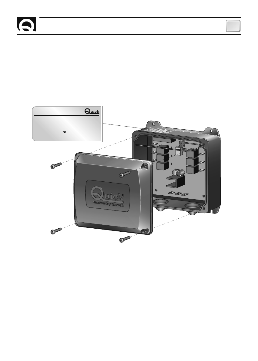
FIG.1
RADIO RECEIVER
Model:R9XX RX RADIO 913MHz X RELAY A00
Code: FRRRCR9XXXXXXXX Rev:XXX
SN: XXXXXX WY: XX/XX
DC INPUT 10.5-31V 0.12A MAX
OUTPUT RELAY: 15+15A, Ton/Toff 17/943s
The RRC radio receiver box must be installed vertically (see fi gure 1), fi xed to the support shelf using four screws
(not supplied) and positioned at a height of at least 1 metre above the fl oating level of the boat.
Pay particular attention when drilling holes on panels or parts of the boat.
These holes must not weaken the boat structure or cause it to break.
The RRC radio receiver is compliant with EMC standards (electromagnetic compatibility) but a correct installation
is required not to compromise the performances of the device and of surrounding equipment.
For this reason the RRC radio receiver must be installed at a distance of at least:
• 1 m from the compass.
• 1 m from motors.
• 1 m from any radio receiver device.
• 1 m radio transmitting device (with the exclusion of SSB).
• 2 m from any SSB radio transmitting device.
• 2 m from the radar beam.
RRC R902/12 - REV001A
5
Page 6
GB
INSTALLATION
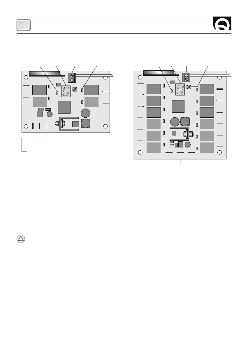
INSTALLATION OF THE RRC RADIO RECEIVER
R902 - R904 R906 - R908 - R910 - R912
LED
ON/OFF
DISPLAY
ANTENNA
CONNECTOR
CONFIGURATION
BUTTON
LED
ON/OFF
DISPLAY
ANTENNA
CONNECTOR
CONFIGURATION
BUTTON
COM
ANT
SHEILD
PROG
V
-
*
*
*
*
*
*
relay 8relay 7
relay 10relay 9
relay 12relay 11
NEGATIVE (-)
POWER SUPPLY
FAST ON
2
O
N
**
4
O
N
**
6
O
N
**
8
O
N
10
O
N
12
O
N
**
NO1
relay 1 relay 2
NO3
COM
+
V
RELAY CONTACTS
COMMON FASTON
POSITIVE (+)
POWER SUPPLY FASTON
* RELAY ACTIVATION LED
** OUTPUT FASTON
*
*
V
-
NEGATIVE (-)
POWER SUPPLY FASTON
ANT
SHEILD
PROG
NO1
**
**
*
relay 4relay 3
*
NO2
NO4
**
**
relay 1 relay 2
N
O
3
N
O
5
NO7
N
O
9
N
O
1
1
*
relay 3 relay 4
*
relay 5 relay 6
*
*
*
*
V
+
POSITIVE (+)
POWER SUPPLY
FAST ON
RELAY CONTACTS
COMMON FASTON
ELECTRICAL CONNECTION
The RRC radio receiver is compliant with EMC standards (electromagnetic compatibility) but a correct installation
is required not to compromise the performances of the device and of surrounding equipment.
For this reason the RRC receiver’s wire must be placed at a distance of at least:
• 1 m from cables that carry a radio signal (with the exclusion of SSB radio transmitters).
• 2 m from cables that carry a radio signal for SSB radio transmitters.
• 1 m from NMEA cables or electrical power lines.
Follow the rules listed here below to implement the electrical system for the RRC radio receiver (see fi g. 2).
WARNING: before connecting or disconnecting cables from the electrical terminals of the receiver, make
sure that it is not powered.
• Power the RRC radio receiver only after verifying that all electrical connections have been carried out properly
and the correct power supply voltage value described on the rating label (fi g.1) positioned on top of the box of
the radio receiver.
• Use faston terminals (not supplied) to connect the cables to the receiver.
• Insert a switch (not supplied) to turn on and off the RRC radio receiver and interrupt the common wire of the
relay contacts. The distance between the switch’s contacts must be at least 3mm.
• Position the switch so that it can be easily reached if it is necessary to shut-off the device to prevent
dangerous situations.
• Correctly decide the size of the wires section, according to their length, for power supply wires, common wires
and those connecting to the devices being used.
• The RRC radio receiver must be powered by the battery using a separate line. Insert a 1A quick fuse (not
supplied) on the power supply line.
• On the “COMMON” input line, insert a fuse (not supplied) of the correct size, according to the absorption of the
used devices.
6
RRC R902/12 - REV001A
Page 7

INSTALLATION - OPERATION
CONNECTION EXAMPLES
R902 - R904 R906 - R908 - R910 - R912
FIG.2
NO1
relay 1 relay 2
*
NO3
COM
V+V
-
FUSE **
1A QUICK ACTING F
COMMON FOR THE
10,5-31Vdc
USED DEVICES
BATTERY
* DEVICES USED IN DIRECT CURRENT
** THE FUSE VALUE MUST BE CHOSEN BASED ON ABSORPTION
OF THE USED DEVICES.
EXTERNAL ANTENNA
If the installation of an external antenna is required, proceed as follows:
• remove the internal antenna, made of an 8 cm long folded wire, from the
ANT input (fi g.3).
• Connect the centre core of the coaxial cable of the antenna to the ANT
input (fi g.4). The metallic shield must be connected to the SHIELD input.
• Coaxial cable during laying must not be throttled and bended at a right
angle. Must also be taken away from heat sources.
• The antenna must be installed vertically at a distance of at least 1 metre
above the boat fl oating level, away from electrical sources of disturbance
and not inside any metal structures.
• Do not install the antenna close to that of other equipment as VHF, radar,
GPS, etc.
FIG.3
ANT
SHEILD
PROG
NO2
relay 4relay 3
1
NO4
*
NO1
relay 1 relay 2
N
O
3
relay 3 relay 4
N
O
5
relay 5 relay 6
N
O
7
*
N
O
9
N
O
1
1
V
+
FUSE **
1A QUICK ACTING F
COMMON FOR THE USED
10,5-31Vdc
DEVICES
BATTERY
FIG.4
ANT
SHEILD
PROG
COM
V
-
2
O
N
4
O
N
6
O
N
relay 8relay 7
relay 10relay 9
relay 12relay 11
EXTERNAL ANTENNA
GB
8
O
*
N
0
1
O
N
2
1
O
N
ANT
SHEILD
ANT
SHEILD
SHEILD
ANT
FUNZIONAMENTO
Start-up
The receiver starts-up once the power supply is connected. After start-up, the ON/OFF LED and all display segments will light up for a short time.
Awaiting signal status
The ON/OFF LED fl ashes slowly. The receiver waits for a valid command from a stored transmitter or for confi guration.
RRC R902/12 - REV001A
7
Page 8

GB
OPERATION
RECEIVER CONFIGURATION
WARNING: during the entire confi guration phase, the receiver’s relays are not active.
WARNING: during the entire confi guration phase of the receiver, the ON/OFF LED will remain off.
Press the confi guration button to enter the receiver’s confi guration menu. The dot on the display lights up to
show that it has been pressed.
Press the confi guration button and keep it pressed; the external segments of the display will light up in rapid
clockwise succession and will then show the letter of the fi rst menu item steadily on. Release the confi guration button.
By quickly pressing and releasing the confi guration button the next item in the menu can be selected (see
confi guration menu table).
Confi guration menu table
DISPLAY DESCRIPTION
In order to confi rm the choice of the menu item, keep the confi guration button pressed until the chosen letter
fl ashes regularly.
Programming function (letter )
This function allows to store the transmitter ID in the receiver’s memory.
The relays will be programmed in sequence, button 1 of the transmitter will correspond to relay 1, button 2 will
correspond to relay 2, and so on.
Once letter has been selected (always on) keep the confi guration button pressed until the letter fl ashes constantly. Release the confi guration button.
Press any key on the transmitter, the letter will start fl ashing quickly to confi rm that transmitter ID has been
stored in the receiver’s memory.
If the transmitter key is pressed for more than 5 seconds, the receiver will exit programming status and go back
to a fi xed .
In sequence other transmitters can be programmed, up to a maximum of 50. Once 10 seconds have passed after
entering the programming function or receiving the last valid ID, the receiver will exit programming status and go
back to letter
Programming without translation
Programming with translation
Filter function
Deleting receiver memory
Exiting the configuration menu
constantly on. It is also possible to exit this function by pressing and releasing the button.
Programming function with translation (letter
)
Besides storing transmitter ID into the receiver’s memory, this function allows to translate the sequence of
active relays based on the button pressed. This function allows to use a single transmitter to control multiple
receivers placed in different spots.
Once letter
has been selected (always on) keep the confi guration button pressed until the letter fl ashes
constantly. Release the confi guration button.
Press the key on the transmitter that has to be matched with relay 1. The letter
will fl ash quickly and confi rm
that the transmitter ID has been entered in the receiver’s memory.
If the transmitter key is pressed for more than 5 seconds, the receiver will exit confi guration status and go back
to a fi xed
.
In sequence other transmitters can be programmed, up to a maximum of 50. Once 10 seconds have passed after
entering the programming function or receiving the last valid ID, the receiver will exit programming status and go
back to letter constantly on. It is also possible to exit this function by pressing and releasing the button.
8
RRC R902/12 - REV001A
Page 9

OPERATION
GB
Example of programming with translation:
Press key 3 on an RRC radio transmitter.
KEY PRESSED
ON THE TRANSMITTER
1
2
3
4
CORRESPONDENCE TO ENABLED RELAY
ON THE RECEIVER
(None)
(None)
1
2
1
3
1
3
2
4
1
2
3
5 6
4
7 8
9 10
11 12
2
4
Key 3 corresponds to relay 1, key 4 corresponds to relay 2.
Filter function (letter )
This function allows to select three different interference noise fi ltering modes within the function submenu
(see table).
The receiver is supplied set in AVERAGE mode.
Filter function submenu table
LOW: select when using in environments with only slight interference
AVERAGE: factory setting. Select when using in normal conditions
HIGH: select when using in environments with great interference
Once selected, letter remains on; keep the confi guration button pressed until letter , or (depending
on the current setting saved in the receiver) fl ash at a constant frequency.
Release the confi guration button. By subsequently quickly pressing and releasing the confi guration button letter
, or (fl ashing at a constant frequency) can be selected. Once the confi guration has been chosen among
those selectable, keep the confi guration button pressed until the letter starts to fl ash at a fast rate, confi rming that
it has been saved; next, the letter will appear and remain on. Release the programming button
After 10 seconds, if the confi guration button is not pressed, it will go back to the letter
being on constantly.
Erasing the memory (letter )
This function allows to erase from the receiver’s memory all transmitter IDs that have been saved using the
or
programming function.
Once letter
constantly on is selected, keep the confi guration button pressed until letter stored fl ashing regularly, passed 3 more seconds, it will start fl ashing at a faster rate. This confi rms that it has been erased and then
the letter remains on. Release the programming button.
If the programming button is released before 5 seconds have passed, letter will go back to being on constantly
and the erasing procedure is cancelled.
Exiting the confi guration menu (
simbol)
This function allows to exit from the confi guration menu of the receiver.
Once the
symbol is selected, keep the confi guration button pressed, the symbol will start fl ashing quickly
before shutting off. Release the confi guration button. When exiting the confi guration phase the ON/OFF LED will
start fl ashing again.
RADIO RECEIVER OPERATION
Reception of a command from the transmitter
When receiving a command from the RRC radio transmitter, the green ON/OFF LED will start fl ashing quickly.
The corresponding relay will activate and its activation is displayed by the red “relay activation” lighting up. Two
relays can be activated at the same time.
RRC R902/12 - REV001A
9
Page 10

GB
SYSTEM ERRORS AND FAULTS - SIGNALS
SYSTEM ERRORS
During the start-up phase the radio receiver can display the presence of system errors.
Flash checksum error
If this error is detected on start-up, the ON/OFF LED fl ashes quickly.
In this case it is necessary to contact the after-sales assistance centre or Quick
®
customer service.
PROBLEMS WITH AUTOMATIC RESET
The reset for this class of problems takes place automatically, as soon as the cause of the problem disappears.
Low power supply voltage. Power supply voltage is less than 9.5 Vdc. When this signal is active, the
relays are deactive. The signal ends when power supply voltage is once again above 9.5 Vdc
SIGNALS
Receiver’s memory is full. The maximum number of transmitters has been reached (50). In order to
add more transmitters it is necessary to complete the memory erasing function (all previously stored
transmitter IDs will be erased).
Signal is only active during the or programming phase.
Transmitter code is already in memory. The signal for this problem is only active during the or
programming phase.
Transmitter ID is not valid. The transmitter cannot be coupled to the receiver in use.
Transmitter ID is not in memory. This signal is displayed when a correct transmitter ID is received but it is
not present in receiver’s memory.
This signal may appear when there is another RRC Quick® system operational in the surrounding area
The radio data packet received contains errors. The receiver has detected an error in the data packet
received due to the presence of interference. If this signal appears frequently, verify that the receiver has
been installed correctly.
RSSI level insuffi cient. The level of the radio signal received is below the threshold value of the selected
fi lter. Verify that the internal or external (if present) antenna has been installed correctly.
Translation function is not possible. The programming with translation function is not possible for the
transmitter type in use.
Display is only active during the programming function.
10
RRC R902/12 - REV001A
Page 11

MAINTENANCE - TECHNICAL DATA
GB
MAINTENANCE
The RRC radio receiver does not require particular maintenance. In order to ensure optimal operation of the remote control, once a year verify cables and electrical connections.
TECHNICAL DATA
MODELS R902 R904 R906 R908 R910 R912
INPUT CHARACTERISTICS
Power supply 10,5 ÷ 31 Vdc
Quiescent current 25 mA
Absorption with 2 relays activated 120 mA
OUTPUT CHARACTERISTICS
Relay number 24681012
Relay contact rating 15A
CHARACTERISTICS OF THE RECEIVER
Frequency 913.7 Mhz
Modulation FSK
Number of transmitters that
can be stored
EMC standard FCC TITLE 47 PART 15 SUBPART B CLASS B
GENERAL CHARACTERISTICS
Operating temperature from -15°C to +70°C
Dimensions (W x H x D) 143 x 141,7 x 61,4 mm
Weight (with all relays installed) 300 g 370 g
This device complies with part 15 of the FCC rules. Operation is subject to the following two conditions:
1) This device may not cause harmful interference, and
2) this device must accept any interference received including interference that may cause undesired operation.
50
DIMENSIONS mm (inch) • R902 • R904 • R906 • R908 • R910 • R912
1
108 (4”
/4)
132 (5”
)
64
)
32
/
27
123 (4”
143 (5” 5/8)
QUICK® RESERVES THE RIGHT TO MODIFY THE TECHNICAL CHARACTERISTICS OF THE EQUIPMENT AND THE CONTENTS OF THIS MANUAL WITHOUT PRIOR NOTICE.
RRC R902/12 - REV001A
/
37
13
/
64
)
141,7 (5”
61,4 (2” 27/64)
11
Page 12

FR
CARACTERISTIQUES ET INSTALLATION
RÉCEPTEUR RADIOCOMMANDE RRC
Le récepteur radio RRC est un dispositif associé à un émetteur radio RRC, apte à commander le fonctionnement
d’appareils ou d’accessoires installés sur des bateaux de plaisance.
Le système radio RRC est une commande radio générale dont le dysfonctionnement ne doit pas procurer
de dommages aux personnes, aux animaux et aux choses.
Les avantages offerts par le récepteur radio RRC sont:
• Alimentation électrique universelle (de 10,5 à 31Vdc).
• Fonctionnement géré par un microcontrôleur.
• Modulation FSK et fréquence 913.7Mhz.
• Large gamme de températures de service ( de -15°C à 70°C).
• Indication de l’état de fonctionnement, erreurs et problèmes du système à l’aide de LEDS et d’un afficheur à
sept segments.
• Protection contre l’inversion de polarité.
• Protection contre la décharge de la batterie.
• 50 émetteurs pouvant être insérés en mémoire.
• Modalités de translation pour activer plusieurs récepteurs installés dans des lieux divers au moyen d’un seul
émetteur.
• Filtre numérique programmable.
• Possibilité d’activer 2 fonctions en même temps.
• Possibilité de branchement à une antenne externe.
INSTALLATION
L’installation du récepteur RRC doit être effectuée par personnel qualifi é.
AVANT D’UTILISER LE RECEPTEUR RADIO, LIRE ATTENTIVEMENT CE MODE D’EMPLOI. EN CAS DE
DOUTES, CONTACTER LE REVENDEUR OU LE SERVICE CLIENTS QUICK®.
Ce dispositif a été conçu et réalisé pour être utilisé sur des bateaux de plaisance.
Tout autre emploi est interdit sans autorisation écrite de la société Quick
F
Le récepteur radio RRC a été conçu et réalisé pour les objectifs décrits dans ce mode d’emploi.
La société Quick® n’assume aucune responsabilité pour les dommages directs ou indirects provoqués par un
usage impropre de la commande radio, une installation erronée ou par des erreurs éventuelles contenues dans
ce mode d’emploi.
Si le récepteur radio RRC est installé sur des bateaux homologués ou classés selon les lois internationales ou les spécifications nationales, l’installateur devra exécuter les demandes conformément à ces
dispositions/classements.
Les consignes contenues dans ce mode l‘emploi ne garantissent pas la conformité avec ces dispositions/classements.
L'EMBALLAGE CONTIENT: récepteur radio - conditions de garantie - le mode d’installation et d'emploi.
12
®
.
RRC R902/12 - REV001A
Page 13

INSTALLATION
FR
INSTALLATION DU RECEPTEUR RADIOCOMMANDE RRC
Ci-après la description d’une procédure d’installation typique.
Il n’est pas possible de décrire une procédure qui puisse s’appliquer à toutes les situations; il faut adapter cette
procédure pour satisfaire ses propres exigences.
Le récepteur radio RRC doit être installé dans une zone sèche, loin des moteurs ou des générateurs électriques;
ces appareils, en effet génèrent un champ électromagnétique irradié qui peut déranger le signal capté par le
récepteur.
Si le récepteur est placé à l’intérieur d’une structure métallique, il est nécessaire d’installer une antenne
extérieure par rapport à la structure; les parois métalliques, en effet, empêchent au signal radio de passer
correctement.
FIG.1
RADIO RECEIVER
Model:R9XX RX RADIO 913MHz X RELAY A00
Code: FRRRCR9XXXXXXXX Rev:XXX
SN: XXXXXX WY: XX/XX
DC INPUT 10.5-31V 0.12A MAX
OUTPUT RELAY: 15+15A, Ton/Toff 17/943s
Le boîtier du récepteur radio RRC doit être installé sur la position verticale (voir fi gure 1), fi xé au plan d’appui par
4 vis (non fournies) et doit être positionné à une hauteur d’au moins 1 mètre au-dessus du niveau de fl ottaison
du bateau.
Faire particulièrement attention au moment de percer les trous sur les panneaux ou sur les parties du bateau.
Ces trous ne doivent pas fragiliser ou provoquer des cassures à la structure du bateau.
Le récepteur radio RRC correspond aux standards EMC (compatibilité électromagnétique) mais une juste installation est nécessaire pour ne pas compromettre ses prestations et celles des appareils situés aux alentours.
C’est pourquoi le récepteur radio RRC doit se trouver à une distance d’au moins:
• 1 m de la boussole.
• 1 m des moteurs.
• 1 m de n’importe quel appareil radio récepteur.
• 1 m de n’importe quel appareil émetteur radio (sauf SSB).
• 2 m de n’importe quel appareil émetteur radio SSB.
• 2 m du parcours du faisceau radar.
RRC R902/12 - REV001A
13
Page 14

FR
INSTALLATION
INSTALLATION DU RECEPTEUR RADIO RRC
R902 - R904 R906 - R908 - R910 - R912
LED
ON/OFF
AFFICHEUR
CONNECTEUR
ANTENNE
BOUTON-POUSSOIR
DE CONFIGURATION
LED
ON/OFF
AFFICHEUR
CONNECTEUR
ANTENNE
BOUTON-POUSSOIR
DE CONFIGURATION
COM
ANT
SHEILD
PROG
*
*
*
*
*
*
V
-
FAST ON
D’ALIMENTATION
NEGATIF (-)
2
O
N
**
4
O
N
**
6
O
N
**
8
relè 8relè 7
relè 10relè 9
relè 12relè 11
O
N
10
O
N
12
O
N
**
NO1
relè 1 relè 2
NO3
COM
+
V
V
FASTON COMMUN
CONTACTS RELAIS
FAST ON
D’ALIMENTATION POSITIF (+)
* LED D’ACTIVATION RELAIS
** FASTON DE SORTIE
*
*
-
FAST ON
D’ALIMENTATION NEGATIF (-)
ANT
SHEILD
PROG
NO1
**
**
*
*
NO2
relè 4relè 3
NO4
**
**
relè 1 relè 2
N
O
3
N
O
5
NO7
N
O
9
N
O
1
1
*
relè 3 relè 4
*
relè 5 relè 6
*
*
*
*
V
+
FAST ON
D’ALIMENTATION
POSITIF (+)
FASTON COMMUN
CONTACTS RELAIS
BRANCHEMENT ELECTRIQUE
Le récepteur radio RRC correspond aux standards EMC (compatibilité électromagnétique) mais une juste
installation est nécessaire pour ne pas compromettre ses prestations et celles des appareils situés aux
alentours. C’est pourquoi les câbles du récepteur radio RRC doivent se trouver à une distance d’au moins:
• 1 m des câbles qui transportent le signal radio (sauf les émetteurs radio SSB).
• 2 m des câbles qui transportent le signal radio des émetteurs radio SSB.
• 1 m des câbles NMEA ou des lignes électriques de puissance.
Suivre les consignes indiquées ci-après pour réaliser l’installation électrique relative au récepteur radio RRC (voir fi g. 2).
ATTENTION: avant de brancher ou de débrancher les câbles des bornes du récepteur, s’assurer que le
courant soit coupé.
• Alimenter le récepteur radio RRC uniquement après avoir contrôlé que tous les branchements électriques
sont exacts et que la valeur de tension d’alimentation indiquées sur la plaque des fi ches situées sur la part
supérieur de la boite du récepteur radio soit correct. (Fig.1)
• Utiliser les bornes faston (qui ne sont pas fournies) pour brancher les câbles au récepteur.
• Introduire un interrupteur (qui n’est pas fourni) pour allumer et éteindre le récepteur radio RRC et interrompre
la ligne du commun des contacts des relais. La distance entre les contacts de l’interrupteur doit être au moins
de 3mm.
• Positionner l’interrupteur de façon qu’il soit facilement accessible si l’extinction de l’appareil sert à éviter des
situations dangereuses.
• Dimensionner correctement, en fonction de leur longueur, la section des câbles d’alimentation, du commun et
de branchement aux points d’utilisation.
• Le récepteur radio RRC doit être alimenté par la batterie au moyen d’une ligne séparée. Introduire un fusible de
1A (qui n’est pas fourni) sur sa ligne d’alimentation.
• Introduire sur la ligne d’entrée “COMMUNE” un fusible (qui n’est pas fourni) dont la dimension doit être en
fonction de la consommation des points d’utilisation
14
RRC R902/12 - REV001A
Page 15

INSTALLATION - FONCTIONNEMENT
FR
EXEMPLE DE BRANCHEMENT:
R902 - R904 R906 - R908 - R910 - R912
FIG.2
ANT
SHEILD
NO1
relè 1 relè 2
*
NO3
COM
V+V
-
PROG
relè 4relè 3
1
FUSIBLE **
1A QUICK ACTING F
COMMUN POINTS
10,5-31Vdc
D’UTILISATION
BATTERIE
* UTILISATEURS EN COURANT CONTINU
** LA VALEUR DU FUSIBLE DOIT ÊTRE CHOISIE EN FONCTION
DE LA CONSOMMATION DES POINTS D’UTILISATION.
NO1
relè 1 relè 2
N
NO2
NO4
*
O
3
relè 3 relè 4
N
O
5
relè 5 relè 6
N
O
7
*
N
O
9
N
O
1
1
V
FUSIBLE **
1A QUICK ACTING F
COMMUN POINTS
10,5-31Vdc
D’UTILISATION
BATTERIE
ANT
SHEILD
PROG
COM
+
V
-
2
O
N
4
O
N
6
O
N
8
O
relè 8relè 7
relè 10relè 9
relè 12relè 11
*
N
0
1
O
N
2
1
O
N
ANTENNE EXTERNE
Si l’installation de l’antenne externe est requise, procéder de la façon suivante:
• enlever, de l’entrée ANT, l’antenne interne (fi g.3) composée d’un fi l plié de 8 cm de longueur.
• Relier le centrale du câble coaxial de l’antenne à l’entrée ANT (fi g.4). La gaine blindée doit être reliée à l’entrée
SHIELD.
• Le câble coaxial pendant la pose ne doit pas être étranglé et pliée à angle
droit. Il doit être tenu loin des sources de chaleur.
• L’antenne doit être installée sur la position verticale à une distance d’au
moins 1 mètre au-dessus du niveau de fl ottaison du bateau, loin des
sources électriques causant des dérangements et non pas à l’intérieur de
structures métalliques.
• Ne pas installer l’antenne près de d’autres équipements comme VHF, radar,
GPS, etc
FIG.3
ANT
SHEILD
FIG.4
ANT
SHEILD
SHE
ANT
ILD
FONCTIONNEMENT
Allumage
Une fois que l’alimentation a été branchée, le récepteur s’allume. Au moment de l’allumage la LED ON/OFF et tous
les segments de l’affi cheur s’éclaireront, brièvement.
Etat d’attente
La LED ON/OFF clignote lentement. Le récepteur attend de recevoir une commande valide d’un émetteur déjà en
mémoire ou d’être confi guré.
RRC R902/12 - REV001A
15
Page 16

FR
FONCTIONNEMENT
CONFIGURATION DU RECEPTEUR
ATTENTION: durant toute la phase de confi guration les relais du récepteur ne seront pas actifs.
ATTENTION: durant toute la phase de confi guration du récepteur la LED ON/OFF restera éteinte.
Pour entrer dans le menu de confi guration du récepteur, presser le bouton-poussoir de confi guration. Toutes les
pressions seront visualisées par l’allumage du petit point de l’affi cheur.
Presser et tenir pressé le bouton-poussoir de confi guration; les segments externes de l’affi cheur s’allumeront
rapidement l’un après l’autre et affi cheront la lettre toujours allumée de la première rubrique du menu .
Lâcher le bouton-poussoir de confi guration.
En pressant rapidement et en lâchant le bouton-poussoir de confi guration, il est possible de sélectionner la
rubrique successive du menu (voir le tableau du menu de confi guration).
Tableau du menu de confi guration
AFFICHEUR DESCRIPTION
Pour confi rmer le choix de la rubrique du menu, tenir pressé le bouton-poussoir de confi guration jusqu’à ce que
la lettre choisie clignote de façon régulière.
Fonction de programmation (lettre )
Cette fonction permet la saisie de l’ID de l’émetteur dans la mémoire du récepteur.
Les relais seront programmés l’un à la suite de l’autre, la touche 1 de l’émetteur correspondra au relais 1, la
touche 2 correspondra au relais 2, ainsi de suite.
Après avoir sélectionné la lettre (toujours allumée) tenir pressé le bouton-poussoir de confi guration jusqu’à
ce que la lettre clignote de façon constante. Lâcher le bouton-poussoir de confi guration.
Presser une touche quelconque de l’émetteur, la lettre clignotera rapidement pour confi rmer la saisie de l’ID
de l’émetteur dans la mémoire du récepteur.
Si la touche de l’émetteur sera tenue pressée pendant plus de 5 secondes, le récepteur sortira de l’état de
programmation et reviendra à la lettre fi xe.
Il sera possible de programmer d’autres émetteurs l’un à la suite de l’autre jusqu’à un maximum de 50. 10 secondes après l’entrée dans la fonction de programmation ou de la réception du dernier ID valide, le récepteur
sortira de l’état de programmation en revenant à la lettre toujours allumée. La sortie de cette fonction peut
avoir lieu même en pressant et en lâchant le bouton-poussoir.
Fonction de programmation avec translation (lettre
Cette fonction permet, outre la saisie du ID de l’émetteur dans la mémoire du récepteur, de déplacer l’ordre des
relais activés selon la touche que l’on presse. Cette fonction permet d’utiliser un seul émetteur pour commander plusieurs récepteur placés dans des lieux différents.
Après avoir sélectionné la lettre
ce que la lettre clignote de façon constante. Lâcher le bouton-poussoir de confi guration.
Presser la touche de l’émetteur à laquelle on souhaite faire correspondre le relais 1. La lettre
dement pour confi rmer la saisie de l’ID de l’émetteur dans la mémoire du récepteur.
Si la touche de l’émetteur sera tenue pressée pendant plus de 5 secondes, le récepteur sortira de l’état de
programmation et reviendra à la lettre fi xe.
Il sera possible de programmer d’autres émetteurs l’un à la suite de l’autre jusqu’à un maximum de 50. 10 secondes après l’entrée dans la fonction de programmation ou de la réception du dernier ID valide, le récepteur
sortira de l’état de programmation en revenant à la lettre toujours allumée. La sortie de cette fonction peut
avoir lieu même en pressant et en lâchant le bouton-poussoir.
16
Programmation sans translation
Programmation avec translation
Fonction filtre
Annulation de la mémoire du récepteur
Sortie du menu de configuration
)
(toujours allumée) tenir pressé le bouton-poussoir de confi guration jusqu’à
clignotera rapi-
RRC R902/12 - REV001A
Page 17

FONCTIONNEMENT
FR
Exemple de programmation avec translation:
En pressant la touche 3 d’un émetteur radio RRC.
TOUCHE PRESSEE
SUR L’ÉMETTEUR
1
2
3
4
CORRESPONDANCE RELAIS ACTIVE
SUR LE RECEPTEUR
(Aucune)
(Aucune)
1
2
1
3
1
3
2
4
1
2
3
5 6
4
7 8
9 10
11 12
2
4
La touche 3 correspondra au relais 1, la touche 4 correspondra au relais 2.
Fonction fi ltre (lettre )
Cette fonction permet de sélectionner dans le sous-menu de la fonction, trois différentes modalités de fi ltrage
des dérangements (voir le tableau).
Le récepteur est fourni avec la confi guration dans la modalité AVERAGE.
Tableau du sous-menu de la fonction fi ltre
LOW: sélectionner pour l’utilisation dans les environnements légèrement dérangés
AVERAGE: configuration de l’usine. Sélectionner pour l’utilisation dans les conditions normales
HIGH: sélectionner pour l’utilisation dans des environnements fortement dérangés
Une fois que la lettre toujours allumée a été sélectionnée, tenir pressé le bouton-poussoir de confi guration
jusqu’à ce que la lettre , ou clignote (selon la confi guration actuelle mémorisée sur le récepteur) avec
une fréquence constante.
Lâcher le bouton-poussoir de confi guration. En pressant ensuite rapidement, puis en lâchant le bouton-poussoir
de confi guration, il sera possible de sélectionner la lettre , ou (clignotant avec une fréquence constante).
Une fois que la confi guration a été choisie entre les trois qui peuvent être sélectionnées, tenir pressé le bouton
poussoir de confi guration jusqu’à ce que la lettre commence à clignoter avec une fréquence rapide pour confi rmer
que la mémorisation a eu lieu; par la suite la lettre toujours allumée apparaîtra. Lâcher le bouton-poussoir de
programmation.
Après 10 secondes si le bouton–poussoir de confi guration n’est pas pressé, on reviendra à la lettre toujours
allumée.
Annulation de la mémoire (lettre )
Cette fonction permet d’effacer de la mémoire du récepteur tous les ID des émetteurs mémorisés par la fonction
de programmation ou .
Une fois que la lettre toujours allumée a été sélectionnée, tenir pressé le bouton-poussoir de confi guration jusqu’à ce que la lettre commence à clignoter à une fréquence régulière ; après 3 autres secondes, elle clignotera
à une fréquence rapide pour confi rmer que l’annulation a eu lieu et redevenir toujours allumée. Lâcher le boutonpoussoir de programmation.
Si le bouton-poussoir de programmation a été lâché avant que les 5 secondes ne se soient écoulées, la lettre
redeviendra toujours allumée et la procédure d’annulation sera effacée.
Sortie du menu de confi guration (symbole )
Cette fonction permet de sortir du menu de confi guration du récepteur.
Après avoir sélectionné le symbol tenir pressé le bouton-poussoir de confi guration, le symbole commencera
à clignoter rapidement puis s’éteindra. Lâcher le bouton-poussoir de confi guration. A la sortie de la phase de
confi guration, la led ON/OFF clignotera de nouveau.
FONCTIONNEMENT DU RECEPTEUR RADIO
Arrivée d’une commande d’un émetteur
Au moment de la réception d’une commande de la part d’un émetteur radio RRC, la LED ON/OFF, de couleur
verte, clignotera rapidement. Le relais correspondant s’activera, et son activation sera visualisée grâce à l’allumage de la LED “activation du relais” de couleur rouge. Il est possible d’activer 2 relais en même temps.
RRC R902/12 - REV001A
17
Page 18

FR
ERREURS ET PROBLEMES DE SYSTEME - SIGNALISATIONS
ERREURS SYSTEME
Durant la phase d’allumage le récepteur radio peut signaler la présence d’erreurs de système.
Erreur checksum fl ash
Au moment de l’allumage, si l’on constate cette erreur, la LED ON/OFF clignote rapidement.
Dans ce cas contacter un point d’assistance ou le service clients Quick
®
.
PROBLEMES AVEC LE RESET AUTOMATIQUE
Le reset de cette classe de problèmes a lieu automatiquement, dès que la cause qui a généré le problème a
disparu.
La Tension d’alimentation est basse. La tension d’alimentation est inférieure à 9,5 Vdc. Quand
cette signalisation est active, les relais sont désactivés. La signalisation terminera quand la tension
d’alimentation sera de nouveau supérieure à 9,5 Vdc.
SIGNALISATIONS
La mémoire du récepteur est saturée. Le nombre maximum d’émetteurs (50) a été atteint. Pour ajouter des
émetteurs supplémentaires, exécuter la fonction d’annulation de la mémoire (tous les ID des émetteurs
mémorisés préalablement seront annulés).
La signalisation est active uniquement durant la phase de programmation
Le code de l’émetteur est déjà en mémoire. La signalisation du problème est active durant la phase de
programmation
L’ID de l’émetteur n’est pas valide. L’émetteur ne peut être associé au récepteur utilisé.
ou
.
ou
.
L’ID de l’émetteur n’est pas en mémoire. Cette signalisation est visualisée quand on reçoit un ID correct de
l’émetteur mais que ce dernier ne se trouve pas dans la mémoire du récepteur.
Cette signalisation pourrait apparaître quand un autre système RRC Quick
Le paquet reçu contient des erreurs. Le récepteur a relevé une erreur dans le paquet de données
reçu provoqué par la présence de dérangements. Si cette signalisation apparaît fréquemment, vérifi er
l’installation du récepteur.
Le niveau RSSI est insuffi sant. Le niveau du signal radio reçu est inférieur à la valeur seuil du fi ltre
sélectionné. Vérifi er l’installation de l’antenne interne ou externe (si elle existe).
La fonction de translation n’est pas possible. La fonction de programmation avec translation n’est pas
possible pour le type d’émetteur utilisé.
La visualisation est active uniquement pendant la fonction de programmation
18
®
est opérationnel.
.
RRC R902/12 - REV001A
Page 19

ENTRETIEN - CARACTÉRISTIQUES TECHNIQUES
FR
ENTRETIEN
Le récepteur radio RRC ne demande pas un entretien particulier. Pour garantir le fonctionnement optimal de la
commande éloignée vérifi er, une fois par an, les câbles et les branchements électriques.
CARACTÉRISTIQUES TECHNIQUES
MODELÈS R902 R904 R906 R908 R910 R912
CARACTERISTIQUES D’ENTREE
Tension d’alimentation 10,5 ÷ 31 Vdc
Absorption du courant en mode veille 25 mA
Absorption avec 2 relais activés 120 mA
CARACTERISTIQUES DE SORTIE
Numéro relais 24681012
Charge maxi du contact du relais 15A
CARACTERISTIQUES DU RECEPTEUR
Fréquence 913.7 Mhz
Modulation FSK
Nombre d’émetteurs pouvant
être mémorisés
Standard EMC FCC TITLE 47 PART 15 SUBPART B CLASS B
CARACTERISTIQUES GENERALES
Température de service de -15°C à +70°C
Dimensions (L x A x P) 143 x 141,7 x 61,4 mm
Poids (avec tous les relais installés) 300 g 370 g
Cet appareil est conforme à la partie 15 des règles de la FCC, son fonctionnement est soumis aux deux conditions suivantes:
1) Cet appareil ne doit pas causer d’interférences nocives, et
2) cet appareil doit accepter toute interférence reçue, y compris les interférences qui peuvent provoquer un fonctionnement
indésirable.
DIMENSIONS mm (inch) • R902 • R904 • R906 • R908 • R910 • R912
1
108 (4”
/4)
50
)
132 (5”
64
)
32
/
27
123 (4”
143 (5” 5/8)
QUICK® SE RÉSERVE LE DROIT D'APPORTER DES MODIFICATIONS AUX CARACTÉRISTIQUES TECHNIQUES DE L'INSTRUMENT ET AU CONTENU DE CE MODE D'EMPLOI SANS AUCUN PRÉAVIS.
RRC R902/12 - REV001A
/
37
13
/
64
)
141,7 (5”
61,4 (2” 27/64)
19
Page 20

RRC R902/R912
RADIO CONTROL RECEIVER
R001A
GB
Product code and serial number
Code et numéro de série du produit
FR
QUICK® S.p.A. - Via Piangipane, 120/A - 48124 Piangipane (RAVENNA) - ITALY
Tel. +39.0544.415061 - Fax +39.0544.415047
www.quickitaly.com - E-mail: quick@quickitaly.com
 Loading...