

Page 1
QuickWorldwide.com
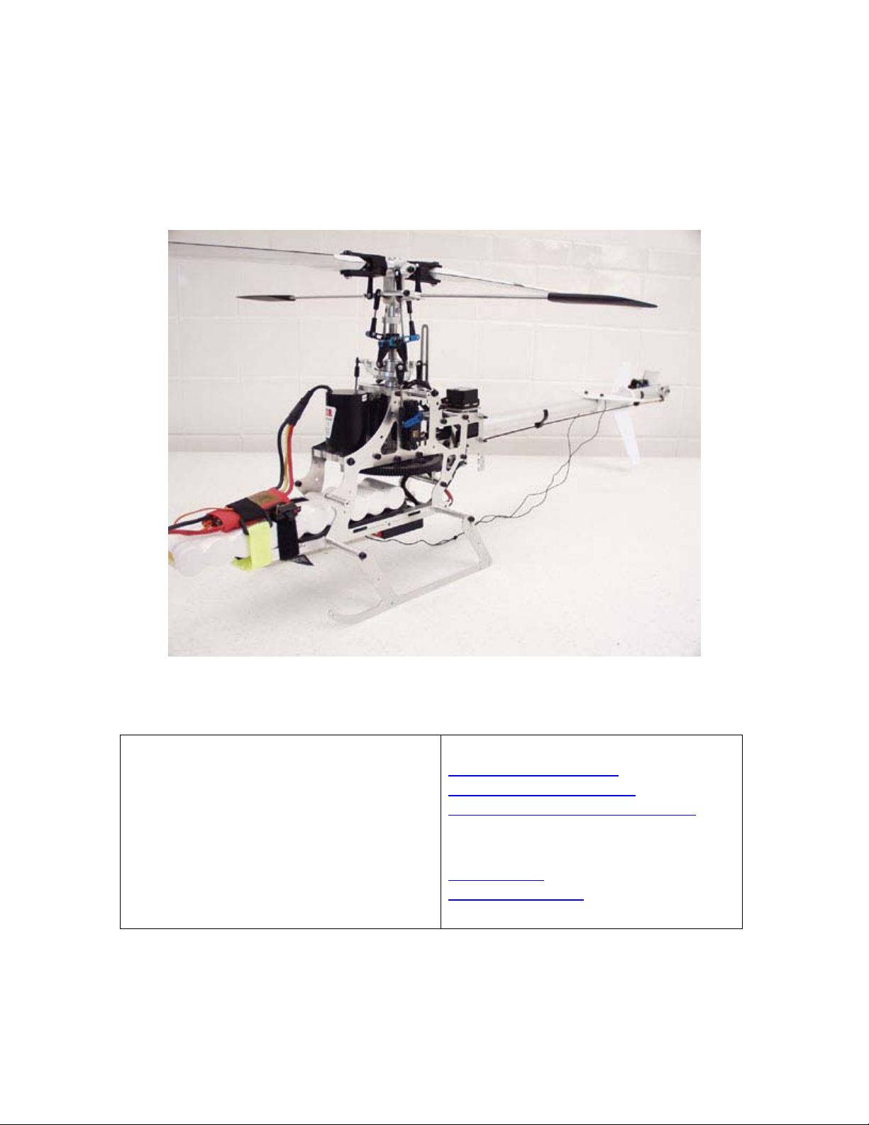
Quickie EP Helicopter
Exclusively distributed by:
Quick Worldwide
201 South 3rd. St. & 309 N.
Coopersburg, PA 18036
Phone: (610)-282-4811
Fax: (610)-282-4816
Websites:
http://www.hhiheli.com
http://www.quickheli.com
http://www.giantscaleplanes.com
E-mail:
hhi@fast.net
Jon@ewtech.com
(Tech. Support)
1
Page 2

Table Of Contents
Introduction......................................................................................................................... 3
Quickie EP Features............................................................................................................ 4
Tools Needed to Assemble the “Quickie EP”..................................................................... 5
Hardware & Accessories..................................................................................................... 6
Other Optional Accessories ................................................................................................ 7
Radio Requirements............................................................................................................ 8
Section 1 – Frame Assembly............................................................................................... 9
Section 2 – Main Gear Installation................................................................................... 13
Section 3 – Counter Gear Assembly ................................................................................. 15
Section 4 – Control Items ................................................................................................. 17
Section 5 – Head Assembly .............................................................................................. 19
Section 6 – Tail Assembly ................................................................................................ 22
Section 6 – Fin Set Installation ......................................................................................... 26
Section 7 – Linkage Rod Installation................................................................................ 27
Step 1 – Linkage Rod Setup.......................................................................................... 27
Step 1A – Shim Ball Installation .................................................................................. 27
Section 8 – Motor Installation........................................................................................... 31
2
Page 3

Introduction
Quick Worldwide & Hobbies & Helis International:
Quick of Japan and Hobbies & Helis International teamed up in 1997 to
manufacture various upgrades for many of the plastic helicopters on the market.
After four years of distributing numerous upgrades and crash parts for other
helicopters, Quick and HHI decided to develop a lin of their own. Starting with the
Quick 60, 30 and Quick Learner, the popularity of the Quick helicopter line
continued to grow. In 2003, Quick and HHI pushed the outside of the envelope
when they released a radical new design in the Quick 50, which immediately
became a tremendous success.
Now, using the same design concepts used
Building on the popularity of this, and severAs the development of the kit began,
initial designs were approved, proto-types were created and flown - all to ensure
that the design was flawless. No minor details were over-looked. After countless
hours of hard work and dedication, Quick-World-Wide is proud to release the first
in a new standard in Helicopters - the Quick Learner.
Warning:
The radio-controlled model helicopter contained in this kit is not a toy.
Rather, it is a sophisticated piece of equipment. This Product is not
recommended for use by children, without adult supervision. Radio controlled
models such as this, are capable of causing both property damage and/or bodily
harm to both the operator/assembler and/or spectator if not properly assembled
and operated. Hobbies & Helis assumes no liability for damage that could occur
from the assembly and/or use/misuse of this product.
AMA:
We strongly encourage all prospective and current R/C aircraft pilots to join the
Academy of Model Aeronautics. The AMA is a non-profit organization that
provides services to model aircraft pilots. As an AMA member, you will receive a
monthly magazine entitled Model Aviation, as well as a liability insurance plan to
cover against possible accident or injury. All AMA charter aircraft clubs require
individuals to hold a current AMA sporting license prior to the operation of their
model.
Pre-Assembly Information:
Quick Helicopters are put together with care and quality topping our priority list. A
recommendation when you are ready to begin building this model is that you
examine the kit and understand the contents of the packages and read
thoroughly before starting the assembly process. Purchase a parts box for all the
nuts, bolts, and other small parts. We take great care to ensure all parts are in
the box.
3
Page 4

Quickie EP Features
1. Frame Construction:
Quickie frames are made of the highest Quality Black G-10 or Carbon Frames.
These frames are not only rigid but will provide excellent vibration absorption
2. Belt driven Tail:
Belt Driven tail is not only a reliable way to drive a tail, but is also very smooth
with low maintenance.
3. High Quality Ball Bearings:
Quickie EP offers ball bearings on all moving parts.
4. EMS Collective System:
The EMS Collective design allows ease of setup with fewer moving parts. EMS
constitutes overall design simplicity and represents the future of helicopter
technology.
5. Heavy-Duty Motor Mount:
The Quickie EP sports a new heavy-duty top motor mount that allows the easy
removal and change of motors and pinions.
6. Control Linkages:
The control linkages that are provided with the Quickie EP are high quality
2.3mm stainless steel rods and the rod ends are made of a high quality Delrin.
7. Single Blade Axle Design:
The single blade axle design is simple very responsive system, with very
consistent flight characteristics.
8. Inside the Frame Battery Mount:
This design provides quick access to the flight battery and lots of protection in
case of a crash.
.
4
Page 5

Tools Needed to Assemble the “Quickie EP”
Phillips Screw Driver
Composite Paddle
Gauges
HHI7000
Ruler
Needle Nose Pliers
Ball End Drivers
HHI7050
HHI7320 – 6pc Nut &
Allen Driver Set
Hobby Knife
Scissors
Bubble Blade Balancer
HHI7010
High Point Balancer
DUB499
Pitch Gauge
HHI7001
Universal Flybar Lock
HHI7040
5
Page 6
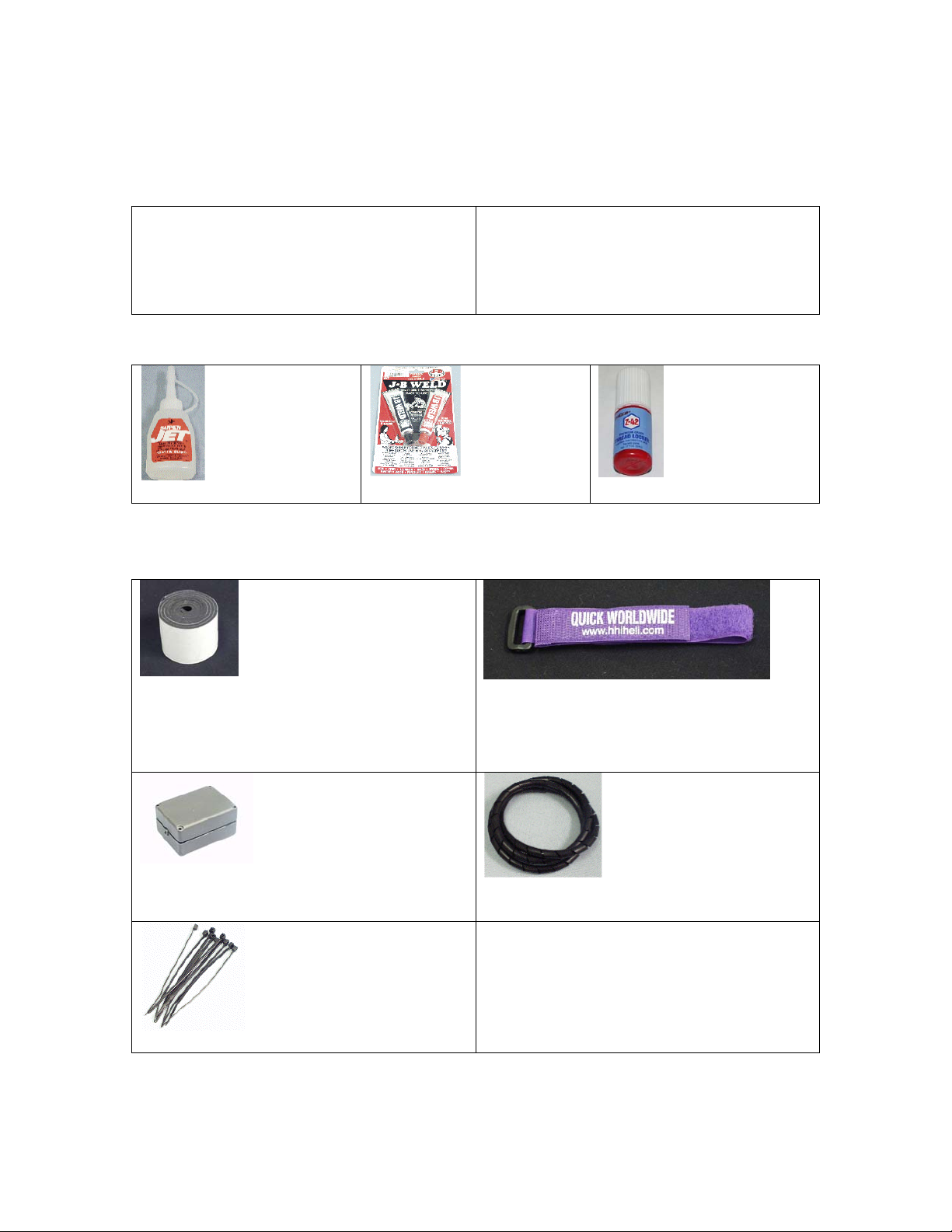
Hardware & Accessories
Motors (These are our recommended motor but others will work)
Glues & Thread Lockers
CA Glue. …GBG1
JB Weld…JBW8265S
Radio Mounting Accessories
Single Sided Foam Tape… HHI2008
Receiver Strong Box… HHI2200
Locktite. …….PT40
Receiver Hold Down Straps
HHI55** $4.99
2 Per Bag & Colors: Red, White,
Purple, Black
Spiral Wrap
HHI2809 & HHI2810
Wire Ties…HHIWT01
6
Page 7
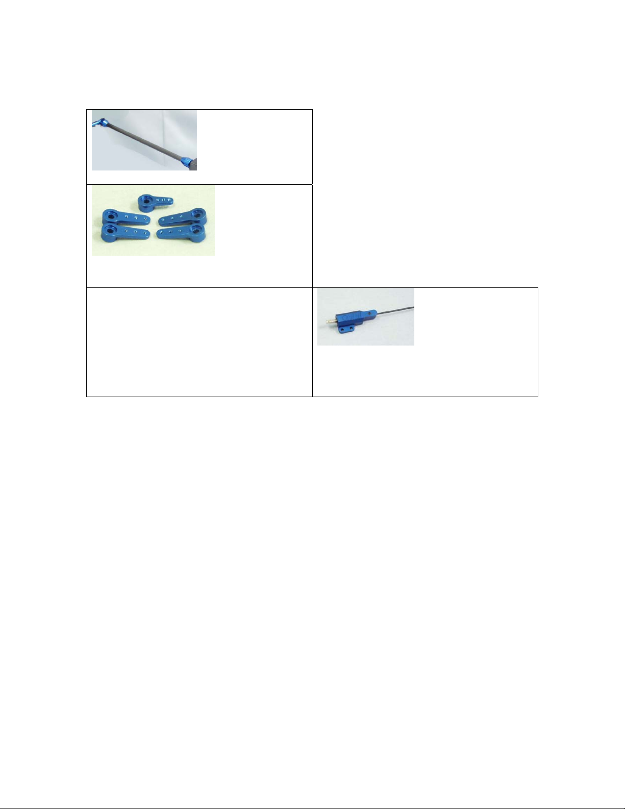
Other Optional Accessories
3mm Fly-bar Stiffeners…HHI402*
Quickie Servo Arm Set
3mm Finishing Caps
HHIM1110
Available in Blue, Silver, Gold, & Purple
Base Load Antenna
HHI53**
Available in Blue, Gold, Purple
& In 40, 50, 72mhz
7
Page 8

Radio Requirements
Radios:
Hobbies & Helis & its distributors carry various lines of helicopter radios. Any
radio that supports EMS/CCPM Mixing will work fine. We recommend using an
eight-channel or better radio, although a six-channel radio is all that is required.
Servos:
This is the single most important function of the helicopter. Any sport servo will
offer acceptable performance. You should be sure to use all the same type of
servo on the swash plate. Higher speed servo is recommended for tail, but not
required.
Introduction:
Please read through the entire manual before starting your construction of the
Quickie. If there are any questions or concerns regarding the assembly of the
helicopter you can call Hobbies & Helis International (610)-282-4811 or Email the
any of the following techs.
Technical Support Personnel:
Jon – Jon@ewtech.com
Threadlocker Warning (Very Important):
This is a general warning about the use of threadlocker and its importance.
Threadlocker must be used anywhere that a metal fastener i.e. (M2, M3, M4 Cap
Head Bolts, Set Screws etc.) are threaded into a metal part i.e. (Bearing Blocks,
Cross-members, etc.). The failure to use threadlocker can result in parts falling a
part and possible loss of control of the model, which can lead to a crash. Also,
be sure to check your bolts’ tightness after each flight. Many bolts, even with the
use of threadlocker can come loose from vibration in the helicopter.
8
Page 9
Section 1 – Frame Assembly
Parts List
Frame Set Bag
Main Frames X 2
Rear Sub-frame x 2
Landing gear x 2
Bag 1
Main-shaft Bearing Block X 2
Canopy Standoffs x 4
Motor Mount x 1
Frame Rails x 2
26mm Landing Gear Standoffs x 4
Antirotation Base x 1
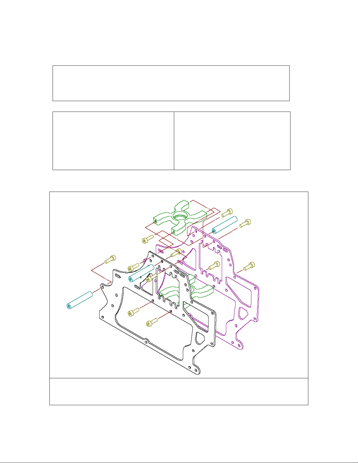
Assemble the main frames as shown in Figure 1. Open part is the bearing block opening that the bearing was inserted into.
Describe which is up or down, a sticker or indent or mark to designate the top part of the bearing block. You may not need the
washers that HHI sells as you want to keep the weight down
9
Page 10
Assemble the main frames as shown in the picture. Attach the canopy standoffs using (4)
M3x6 cap head screws. The bearing blocks will be inserted as follows; the upper block
will have the open part facing up, and the lower bearing block will have the open face
down. Each of the bearing blocks are attached with (4) M3x6 cap head screws.
Loosely install the motor mount.
This item will be coming out again
when you install your motor, so only
put this mount in loosely. Install the
motor mount (4) M3x6 cap head
screw and (4) M3 washers
Next, install the frame rails. The flat
part of the frame rail is oriented on
top. The slotted sides go against the
frames. Install the two 46mm cross
members into the frame. The frame
rails go on the inside of the frames.
Next put an M3x20 set screw into
each of the cross member ends. There
should be a bit still protruding.
10
Then attach a 26mm Landing gear
standoff onto each of the M3x20 set
screws. Attach the landing gear using
(4) M3x6 cap head screws.
Note that if you have problems
getting the standoff to screw down
entirely, remove it and use a hex head
driver to drive the screw into the
standoff, as there might be a little
excess material.
Page 11

Attach the antirotation upright piece
to the antirotation base using (2)
M3x6 cap head screws.
Attach the antirotation guide using
(4) M3x6 cap head screws and (4)
M3 washer.
When installing the antirotation
guide, do not tighten at first until after
the swash is installed.
11
Assemble the rear sub-frame as
shown. Attach the two frame halves
with the boom holders. They will be
attached using (4) M3x35 cap head
bolts and nuts.
Remove the two boom holders from
the bag with the tail rotor parts.
Page 12

Next you will attach the rear sub
frame to the helicopter.
There are eight attachment points,
four on each side. Take an M3x20
cap head screw and slide it through
the hole on the frame. Next, slide a
10mm spacer onto each of the bolts.
Slip the sub-frame into the middle
and secure each bolt with a 24mm
cross member in the middle.
When assembling the rear frame, do
not tighten all of the screws until you
loosely install and start all of the
M10 and M24 cross members. This
will take a little time so be patient.
12
Page 13

Section 2 – Main Gear Installation
Parts List
Bag 2
Main Gear
Autorotation Hub-Deluxe/Main Gear
Hub-Standard
M3x6 Cap Head Screws x 4
Main Shaft x 1
Main Shaft Collar x 1
M3x18 Cap Head Screw x 1
M3 Locknut x 1
M3x3 Set Screw x 4
Next, attach the main gear to the
antirotation/main gear hub as
shown. It will be attached with
(4) M3x6 cap head screws.
When attaching the antirotation
hub to the main gear, you may
need to open the holes slightly.
Use a hobby knife to gently open
the holes so that the M3x6 screws
will easily screw into the plastic.
Slide the main shaft down
through the upper and lower
bearing blocks and into the
autorotation hub. Note that the
smaller diameter part of the shaft
goes into the gear and
autorotation hub.
Secure the shaft in place with an
M3x18 cap head bolt and M3
locknut. Then secure the main
shaft on top with the main shaft
collar and (4) M3x3 set screws.
Pull up on the shaft when
tightening the setscrews to
remove any possible endplay.
13
Page 14

This is how the helicopter should
look at this point.
14
Page 15
Section 3 – Counter Gear Assembly
Parts List
Bag 3
Counter Gear Shaft x 1
Counter Gear x 1
Lock Pin x 1
E-Clip x 1
Counter Gear Bearing Block x 2
Pulley Gear Plate x 1
Lock Pin x 1
Pulley Gear x 1
E-Clip x 1
M3x6 Cap Head Screw x 8
M3 Washer x 8
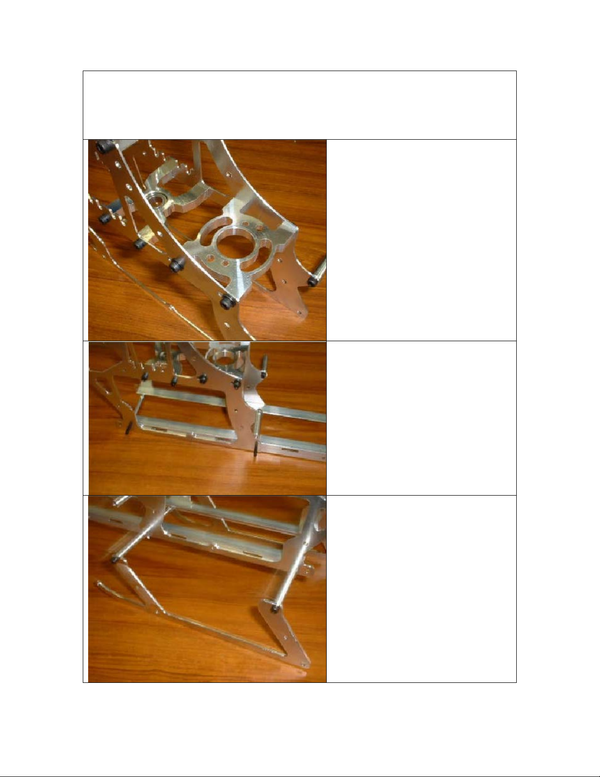
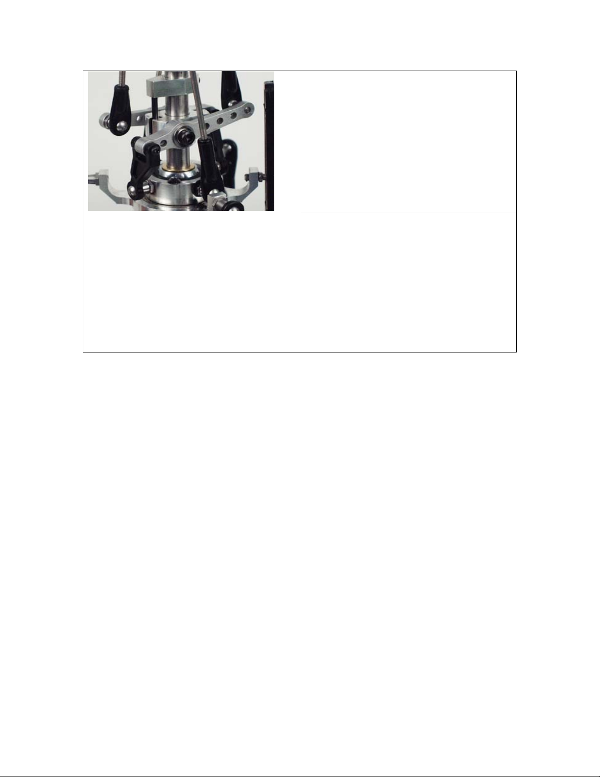
Install the steel stopper pin into the
counter gear shaft. Then slide the
counter gear onto the counter gear
shaft.
Secure the gear in place using an Eclip.
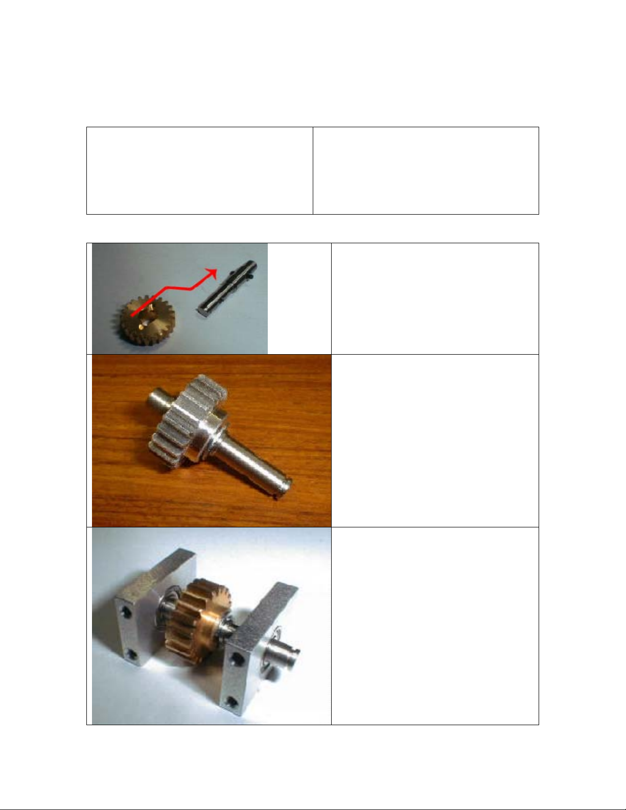
Locate the two counter gear bearing
blocks. Next slide each bearing block
onto the counter gear shaft. Each
bearing block has an open face. The
open faces should both face up as
shown in the picture.
15
Page 16
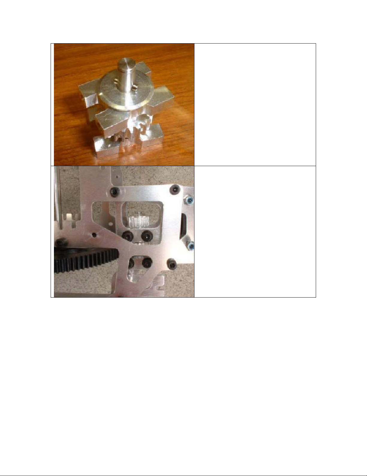
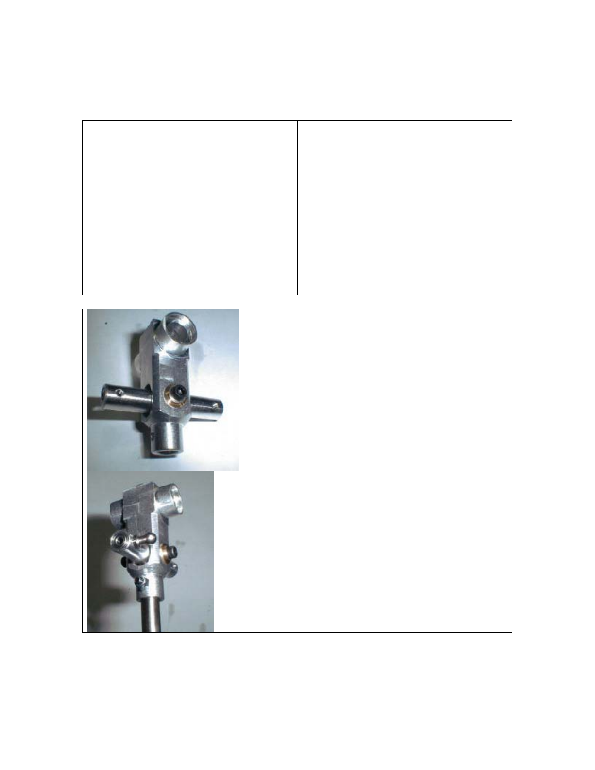
Then slide the pulley spacer on, with
the shoulder down and the bevel side
up, and finally the cross locking pin.
Next slide the gear on the shaft
capturing the cross pin with the slot in
the gear. Secure the gear down with
the second e-clip.
Next, slide the counter gear assembly
into the frame and secure it in place
using (8) M3x6 cap head screws with a
M3 washer under each.
16
Page 17
Section 4 – Control Items
Parts List
Swashplate
Washout Arms
Washout Base
Antirotation guide pin
Washout link x 2
M2x12 Pan head screw x 2
M3x3 Set Screw x 1
M3x6 Pivot studs x 2
M3x10 Cap head screws
M3x5x1 Spacer x 2
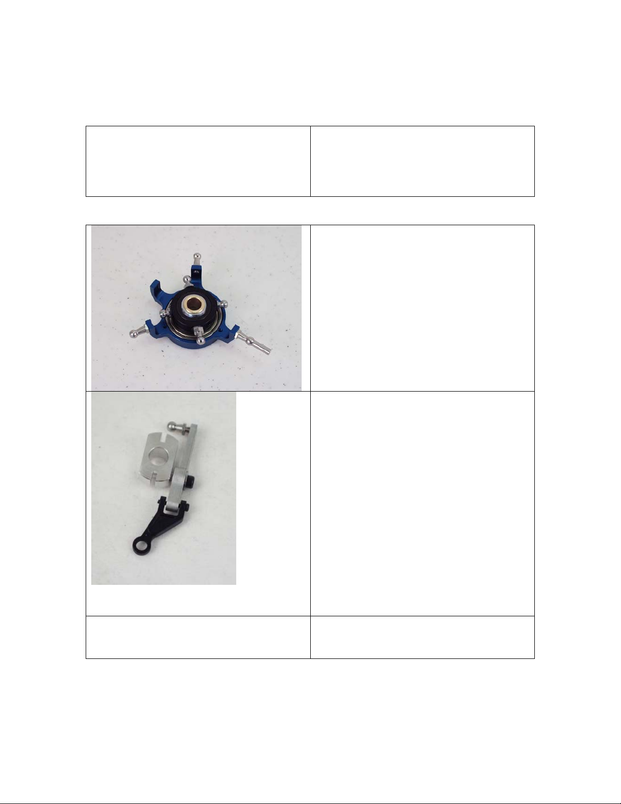
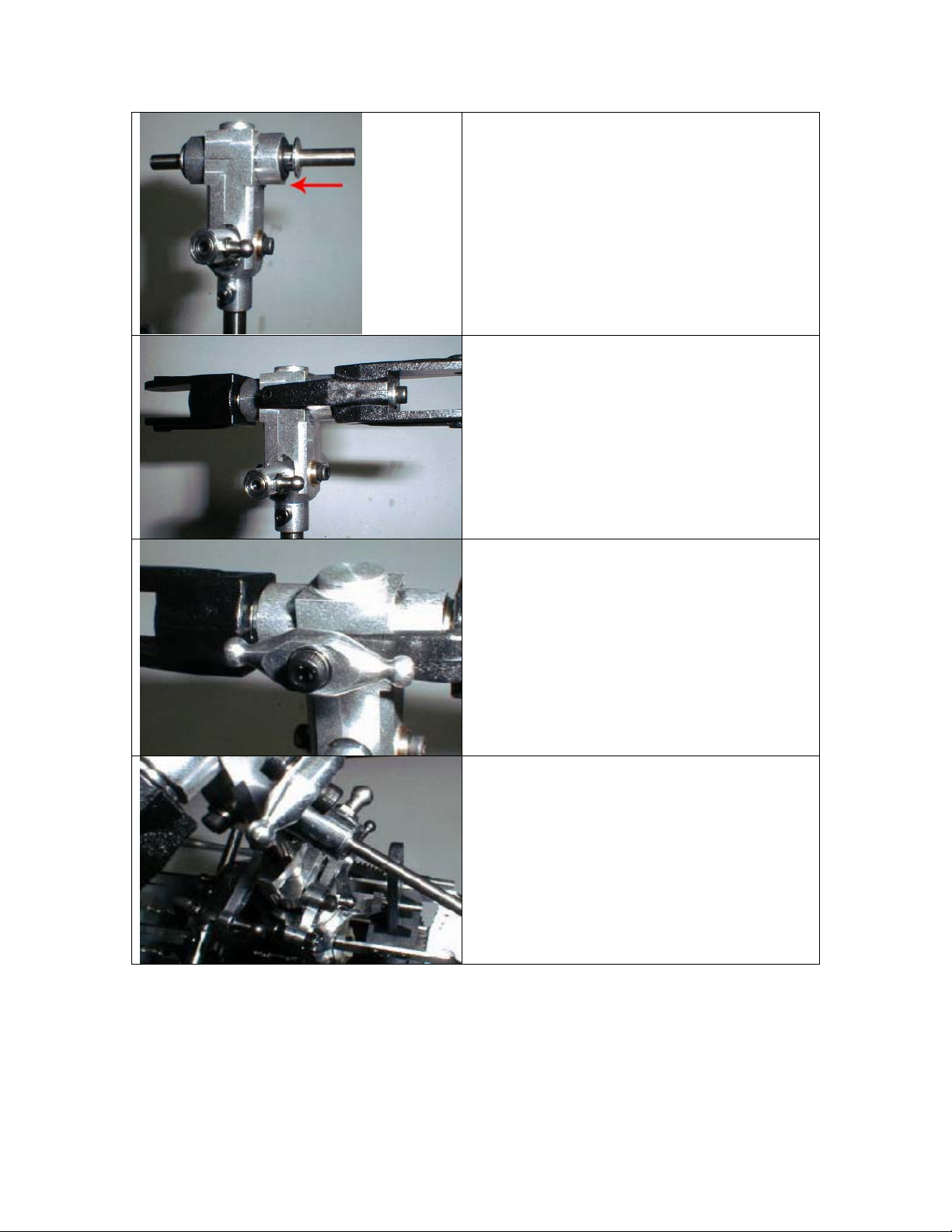
Install the antirotation pin/elevator ball
on to the swashplate. Install the two
sim balls on to the the swashplate as
shown. Locate the swashplate and
slide it on the main shaft first.
Next locate the washout base, arms,
links, M3x6 pivot studs, M3x10 cap
head screws, M3x5x1 spacers, and
M2x12 pan head screws. First slide an
M3x8 cap head screw through each
arm. Note which direction the screw
should go through the arm in the
picture. Slide an M3x5x1 on each bolt
and attach them to the base.
Next attach an M3x6 pivot stud to each
of the washout arms. Finally attach a
washout link to each arm with an
M2x12 pan head screw. Next slide the
washout onto the main shaft with the
protruding side going down first.
Attach the washout links to the longer
pivot studs on the inner ring of the
swashplate.
17
Page 18
Attach the washout links to the longer
pivot studs on the inner ring of the
swashplate.
Slide the Antirotation guide pin on the
main shaft next. Secure it using the
M3x3 set screw. This will be adjusted
later, so snug is all this screw needs to
be for now.
18
Page 19
Section 5 – Head Assembly
Parts List
Center Hub
Seesaw
Seesaw Collar x 2
M3x8 Cap head screw x 2
M3x6 Pivot studs x 2
M3x16 Cap head bolt
M3 Locknut
7x13x3 O-ring x 2
O-ring spacer x 2
Spindle
5x10x4R Bearing x 4
M3x10 Cap head screw
3x8x1 Washer x 2
Hiller arm x 2
M3x10 Cap head screw x 2
3x5x1 Spacer x 3
Flybar
Flybar control arm base x 2
Flybar control arm extension x 2
Flybar control arm spacer (3x5x5) x 2
M4x4 Set screw x 2
M3x8 Cap head screw x 2
Flybar paddle x 2
Blade Grip x 2
M3x24 Cap head bolt x 2
M3 Locknut x 2
Locate the head block, seesaw, seesaw
collars, and (2) M3x8 cap head screws. Slide
the seesaw into the opening on the head
block. Slide a seesaw collar into each of the
bushings on the head block. Secure the
seesaw using the (2) M3x8 cap head screws.
Be sure not to over tighten the seesaw
collars. Use threadlocker on the bolt to
secure it.
Locate (2) M3x6 pivot studs and (2) 3x5x1
spacers. Install the two pivot studs with
3x5x1 spacer into the seesaw. They should
be in holes opposite of each other. The other
two holes tapped in the seesaw will be
unused.
Attach the head block to the main shaft using
the M3x16 cap head bolt and an M3 locknut.
19
Page 20
Install two 7x13x3 o-rings into the head
block. Next slide the head spindle through
the o-rings. Then slide the head dampener
spacers onto the spindle
Each blade grip will have (2) 5x10x4R
bearings. Install the bearings into the blade
grips. Slide each one onto the spindle shaft.
Secure the blade grips to the spindle using
(2) M3x10 cap head screws. Place a 3x8x1
spacer under each bolt before installing them.
Attach each hiller arm to the blade grip using
an M3x10 cap head screw. Put the bolt
through the hiller arm and put a 3x5x1 spacer
on the bolt next, and screw it into the blade
grip.
Note that the open side should be towards
blade grip. Do this before mounting the
spindle.
Slide the flybar through the seesaw.
20
Page 21
Locate two 3x5x5 spacers, two flybar control
arm bases, two flybar control arm extensions,
and two M4x4 set screws. Slide (2) 3x5x5
spacers onto the flybar with the protruding
side going against the seesaw. Next slide the
flybar control arm bases onto the flybar.
They face in opposite directions and oppose
the M3x6 pivot studs on the seesaw
previously installed. Secure them with (2)
M3x5 set screws. Be sure that they are
parallel with each other and that the flybar is
equally distant from both ends.
You may find it easier to assemble the flybar
assembly before mounting the head.
Attach the (2) flybar control arm extensions
using (2) M3x8 cap head screws.
This needs to happen before the flybar
control arms are installed on to the flybar.
Note the side that the flybar control arm is
facing.
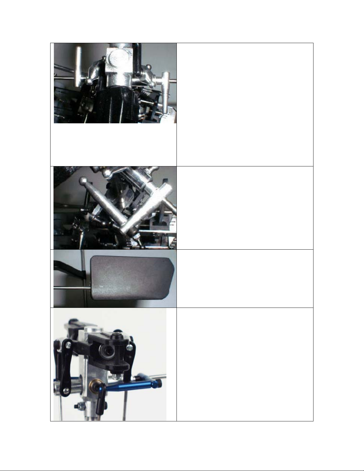
Screw each paddle onto the flybar 25mm. Be
sure the paddles are parallel with each other.
Also the paddles should be inline/parallel
with the flybar control arms.
Use M3x24 cap head bolts with M3 locknuts
to attach each blade to the grip.
21
Page 22
Section 6 – Tail Assembly
Parts List
Tail boom
Belt
Boom holder half x 2
M3x35 x 4
M3 Locknut x 4
Tail output shaft
Pulley gear
M3 set screw x 2
Tail case side plate x 2
5x10x4R Bearing x 2
Tail pitch lever base
M2x6 Pan head screw x 2
M3x6 Cap head screw x 6
Tail Pitch Slider
M3x4 Pivot Stud
2.3 Medium ball ends
Tail Pitch Lever
M3x4 Pivot stud
M3x10 Cap head screw
M3x3 Set screw
Tail rotor hub
Tail blade grips x 2
3x7x3R Bearing x 2
M3x6 cap head screw x 2
M2x8 Pan head screw x 2
Shim ball x 2
Tail blades x 2
M3x20 Cap head screw x 2
M3 Locknut x 2
Tail blade spacers x 4
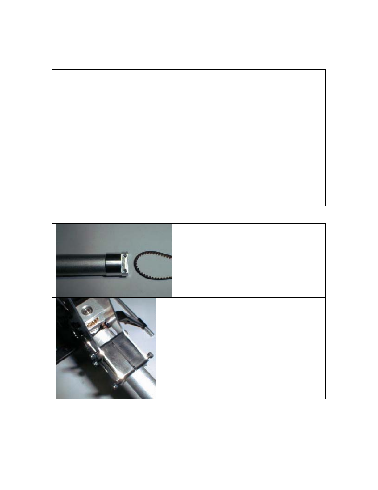
Locate the tail boom and the belt. Slide the belt
through the boom. Be sure you do not twist the
belt.
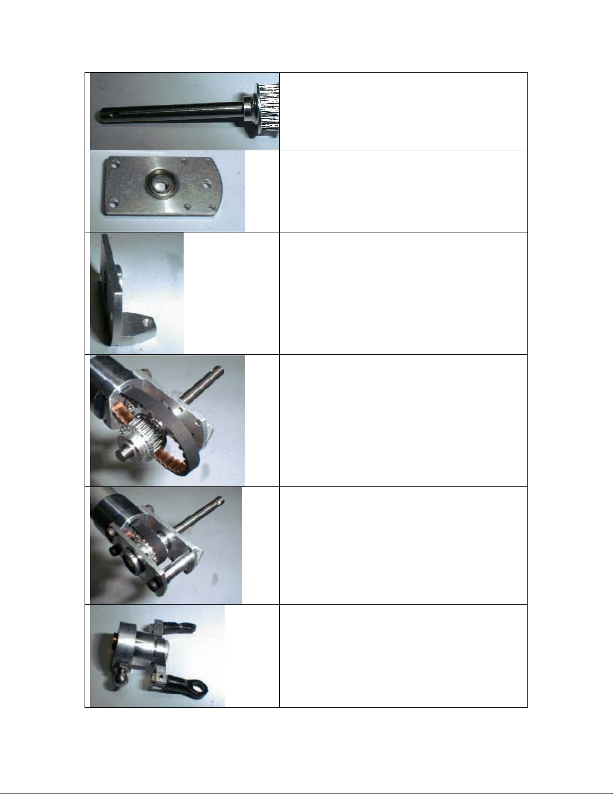
Install the two boom halves into the frames. Put
the (4) M3x35 cap head screws through the four
open holes in the boom halves. Loosely put the
nuts on the ends of the bolts.
22
Page 23
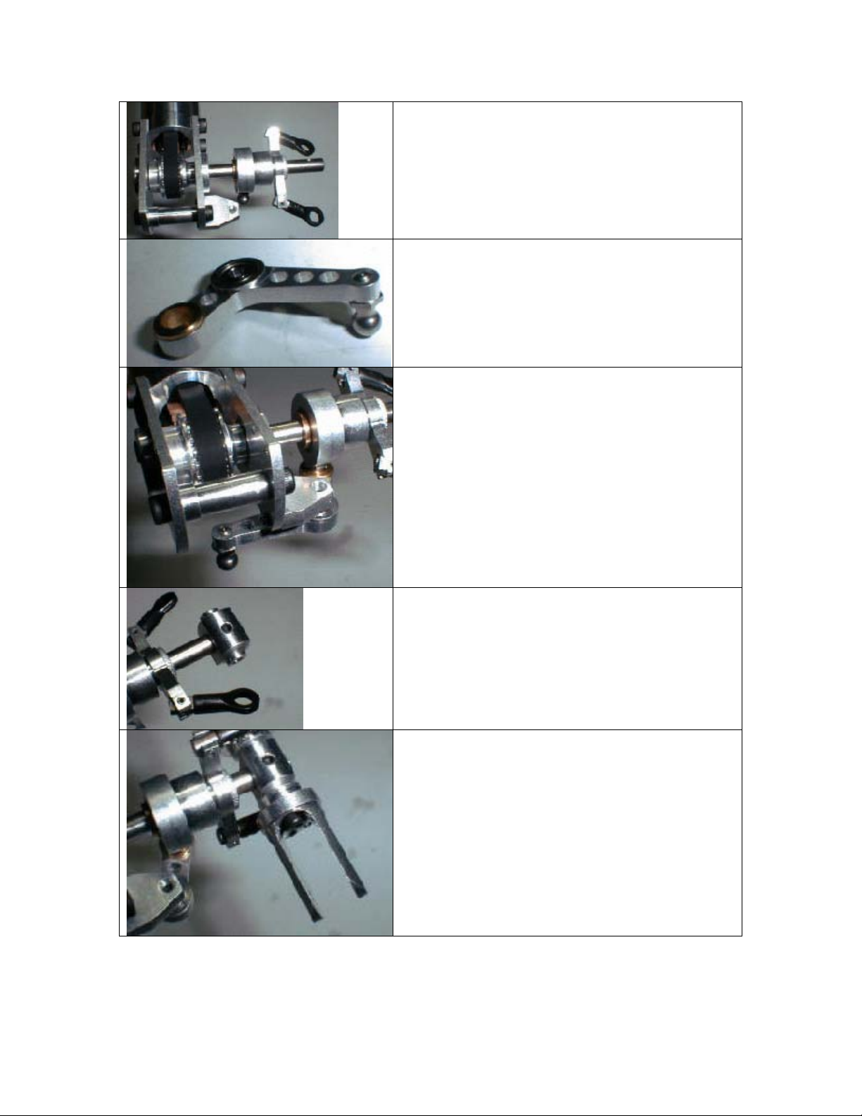
Locate your tail output shaft and tail pulley gear.
Secure the gear to the shaft using (2) M3x3 set
screw.
The set screw should align with the hole in the
shaft and installs on the longer end
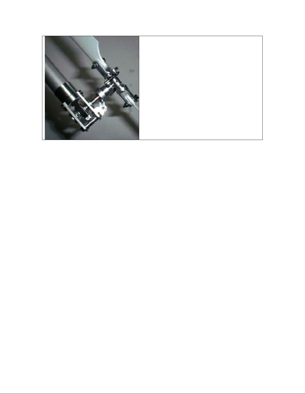
Locate your two tail case side plates. Install a
5x10x4R Bearing into each plate.
Attach the tail pitch lever mount to the side plate
using (2) M2x6 pan head screws.
Attach the side plate to the boom using two
M3x6 cap head screws. Next slide your tail
output and shaft through the side plate.
Attach the other tail case side plate to the tail
boom using (2) M3x6 cap head screws. Also
attach the tail case cross member using (2) M3x6
cap head screws.
Locate your tail pitch slider, (2) medium ball
ends, and an M3x4 pivot stud.
23
Page 24
Slide the tail pitch slider assembly onto the tail
output shaft.
Attach the M3x4 pivot stud to the tail pitch lever.
Attach the tail pitch lever to the tail pitch lever
base using an M3x10 cap head screw. Be sure
that you capture the M3x4 pivot stud in the tail
pitch slider with the brass coupler in the tail
pitch lever.
Attach the tail rotor hub to the tail output shaft
using an M3x3 set screw.
Install a 3x7x3R bearing into each tail blade grip.
Then attach each grip to the tail rotor hub using
an M3x6 cap head screw.
Install a shim ball onto each blade grip using an
M2x8 pan head screw. They should go in the
outmost holes.
24
Page 25
Attach a tail blade to each grip using (2) tail
blade spacers, an M3x20 cap head bolt, and an
M3 locknut.
Note: The Tail Blades should rotate counter
clockwise when looking at the right side of the
Tail Case.
25
Page 26

Section 6 – Fin Set Installation
Parts List
Vertical Fin
Horizontal Fin
C-clamp x 2
M3x14 Cap head screw x 4
Attach the horizontal fin using one c-clamp
and (2) M3x14 cap head screws.
Note: Be sure the fin doesn’t interfere with
the tail blades when they are rotating.
Attach the vertical fin using one c-clamp
and (2) M3x14 cap head screws.
26
Page 27
Section 7 – Linkage Rod Installation
Parts List
M2x8 Pan head screws x 6
Shim ball x 6
M2.3x35mm Linkage Rod x 3
M2.3x50mm Linkage Rod x 3
M2.3x20mm Linkage Rod x 2
2.3mm Ball end, Medium x 8
Tail Rotor Pushrod guide set. (Clips,
two inner sleeves (2))
Attach each servo using (4) M3x14 Cap head screws and (4) M3 Locknuts. Look at the
pictures that follow for the proper servo orientation.
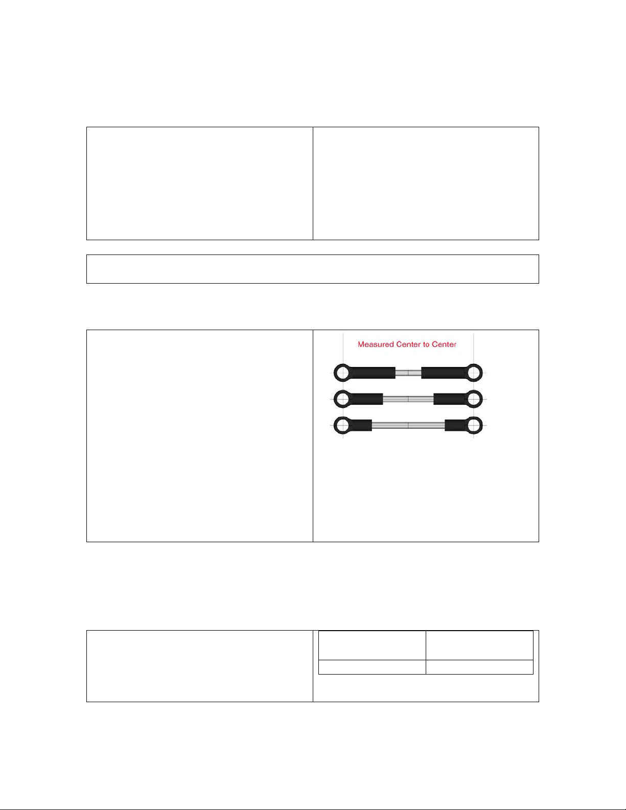
Step 1 – Linkage Rod Setup
In the following table the linkages will
be measured center to center as per
the picture. The table explains the
amount of rods you need to make and
which ball links to use on each end.
This will get the helicopter close to
finished setup, as always you will need
to make some final adjustments to
maximize the performance of your
Helicopter
Replacement Part #:
Linkage Rod Set – QC150
All Linkages available individually just
know the size
2.3mm Ball end, Long x 10
Double Link x 2
Canopy
Rubber grommets x 4
M3x14 Cap head screws x 4
Stainless rudder control rod end x 2
M3x14 Cap head screw x 40
M3 Locknut x 40
Step 1A – Shim Ball Installation
Install (6) Shim Balls using (6) M2-8
Phillips Screws. Install each Shim ball
as close to the recommended distance
for the center of the servo splice and
the center of the shim balls.
Swashplate
Servos
Rudder Servo 11.75-13mm
27
18-20mm
Page 28

All three swashplate rods will
be the same length.
# of Rods
Rod Size
Ball Link 1
Ball Link 2
Center to
Center
3
2.3-35
Medium
Medium
50mm
Pitch and aileron servo arm balls are mounted on the inside.
Elevator ball is mounted facing outside of the servo arm.
Rod Use
# of Rods
Rod Size
Ball Link 1
Ball Link 2
Center to
Center
Washout to
Flybar Control
Arm
1
2.3-20
Medium
Medium
38mm
28
Page 29

Seesaw to Hiller Arm
Use a double link on this spot.
Assemble the push rod guides.
There are three pieces the main
clip and two inner sleeves.
Simply slide the two sleeves
into each other and then into the
main clip and glue. Putting
electrical tape onto the boom
before gluing is good, so it is
possible to reuse the clip later.
(HHI2900 – Rod Guides)
Install the carbon rudder control
rod. The rod should end up 22”
or 558mm long from ball to
ball. Slide the carbon rod
through the guides and glue the
ends on. Screw the links onto
the ends and attach to the balls.
29
Page 30

Swashplate to
Rod Use
# of Rods
Rod Size
Ball Link 1
Ball Link 2
Center to
Center
Hiller arm
2
2.3-50
Long
Long
83mm
Place the canopy where you
like, mark the holes for the
canopy standoffs. Use a ¼”
drill bit. Place the grommets in
the holes and secure the canopy
to the helicopter using (4)
M3x14 cap head screws.
30
Page 31
Section 8 – Motor Installation
Parts List
M3x6 Cap Head Screw x 2
Pinion Gear x 1
M3x5 Set Screw x 1
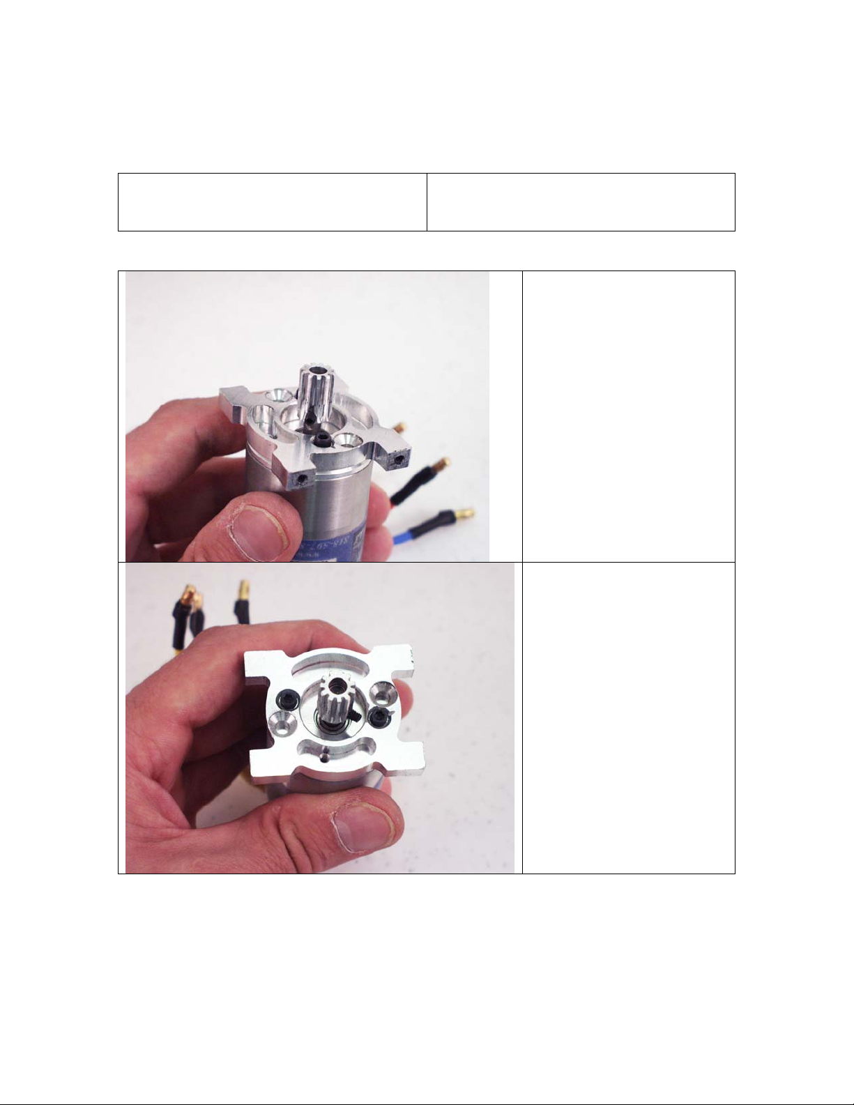
Attach your pinion gear to
the motor using an M3x5 set
screw. It is recommended to
grind a flat onto the output
shaft of the motor if there is
not already one there. This
will help to prevent the gear
from slipping.
Attach the motor to the
motor mount using (2) M3x6
cap head screws.
31
Page 32
Finally install the motor
assembly into the helicopter.
Be sure not to set the gear
mesh too tight or too loose.
A good way to set the mesh
is to slide a piece of
notebook paper between the
gears and then tighten the
bolts. This will give an idea
mesh.
32
 Loading...