

Page 1
QuickWorldwide.com
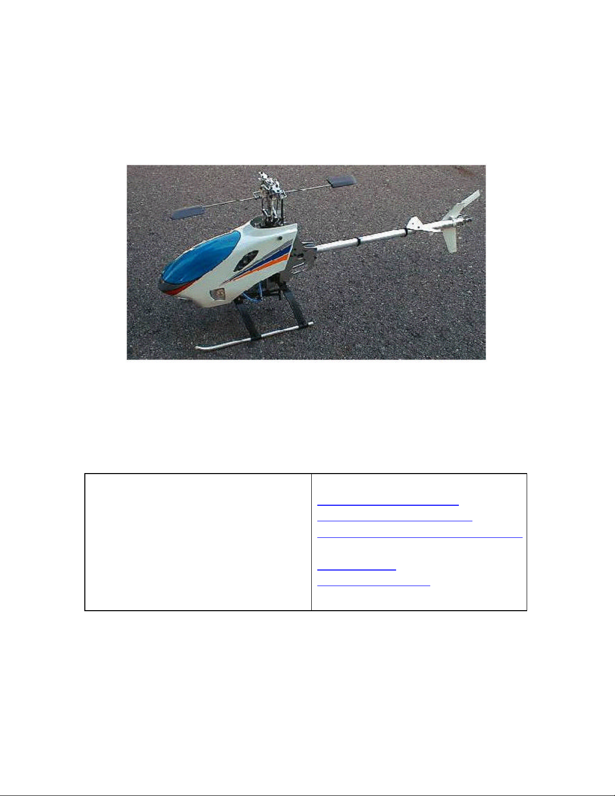
Quickie .15 Helicopters
Exclusively distributed by:
Quick worldwide
201 South 3rd. St. & 309 N.
Coopersburg, PA 18036
Phone: (610) -282-4811
Fax: (610) -282-4816
Websites:
http://www.hhih eli.com
http://www.quickheli.com
http://www.giantscaleplanes.com
E-mail:
hhi@fast.net
Jon@ewtech.com (Tech.
Support)
Page 2

Quick Pre -Assembly Information
Quick Worldwide & Hobbies & Helis International:
Quick of Japan and Hobbies & Helis International teamed up to make parts 6
years ago. In the beginning, our specialty was the manufacturing of various
upgrade parts for many of the plastic helicopters on the market.
After four years of distributing numerous upgrades and crash parts for other
helicopters, we decided to develop our own line of helicopters. That's when the
notion of the Qu ick Learner was conceived. As the development of the kit began,
initial designs were approved, proto-types were made and flown - all to ensure
that the design was flawless. No minor details were over-looked. After countless
hours of hard work and dedication, Quick-World-Wide is proud to release the first
in a new standard in Helicopters - the Quick Learner.
Warning:
The radio-controlled model helicopter contained in this kit is not a toy.
Rather, it is a sophisticated piece of equipment. This Product is not
recommended for use by children, without adult supervision. Radio controlled
models such as this, are capable of causing both property damage and/or bodily
harm to both the operator/assembler and/or spectator if not properly assembled
and operated. Hobbies & Helis assumes no liability for damage that could occur
from the assembly and/or use/misuse of this product.
AMA:
We strongly encourage all prospective and current R/C aircraft pilots to join the
Academy of Model Aeronautics. The AMA is a non-profit organization that
provides services to model aircraft pilots. As an AMA member, you will receive a
monthly magazine entitled Model Aviation, as well as a liability insurance plan to
cover against possible accident or injury. All AMA charter aircraft clubs require
individuals to hold a current AMA sporting license prior to the operation of their
model.
Pre-Assembly Information:
Quick Helicopters are put together with care and quality topping our priority list. A
recommendation when you are ready to begin building this model is that you
examine the kit and understand the contents of the packages and read
thoroughly before starting the assembly process. Purchase a parts box for all the
nuts, bolts, and other small parts. We take great care to ensure all parts are in
the box.
Page 3

Quickie .15 Features
1. Frame Construction: Quickie frames are made of the highest
Quality Black G-10 Frames. These frames are not only rigid but will
provide excellent vibration absorption.
2. Hex Start Shaft System: Allows the helicopter to be started with a
regular start shaft. Kit can also be fitted with a pull-start.
4. Belt driven Tail: Belt Driven tail is not only a reliable way to drive
a tail, but is also very smooth and low maintenance.
5. High Quality Ball Bearings: Quick Learner offers ball bearings on
all moving parts.
6. EMS Collective System: The EMS Collective design allows ease
of setup with fewer moving parts. EMS constitutes overall design
simplicity and represents the future of helicopter technology.
7. Heavy-Duty Clutch System: Same material used in all of our
quick upgrade clutches.
8. Control Linkages: The control linkages that are provided with the
Quick Learner Kit are high quality 2.3mm stainless steel rods and the
rod ends are made of a high quality Delrin.
9. Single Blade Axle Design: The single blade axle design is simple
very responsive system, with very consistent flight characteristics.
11. Rearward facing Engine Design: This design provides quick
access to the glow plug and is advantageous for easy engine
removal.
Page 4
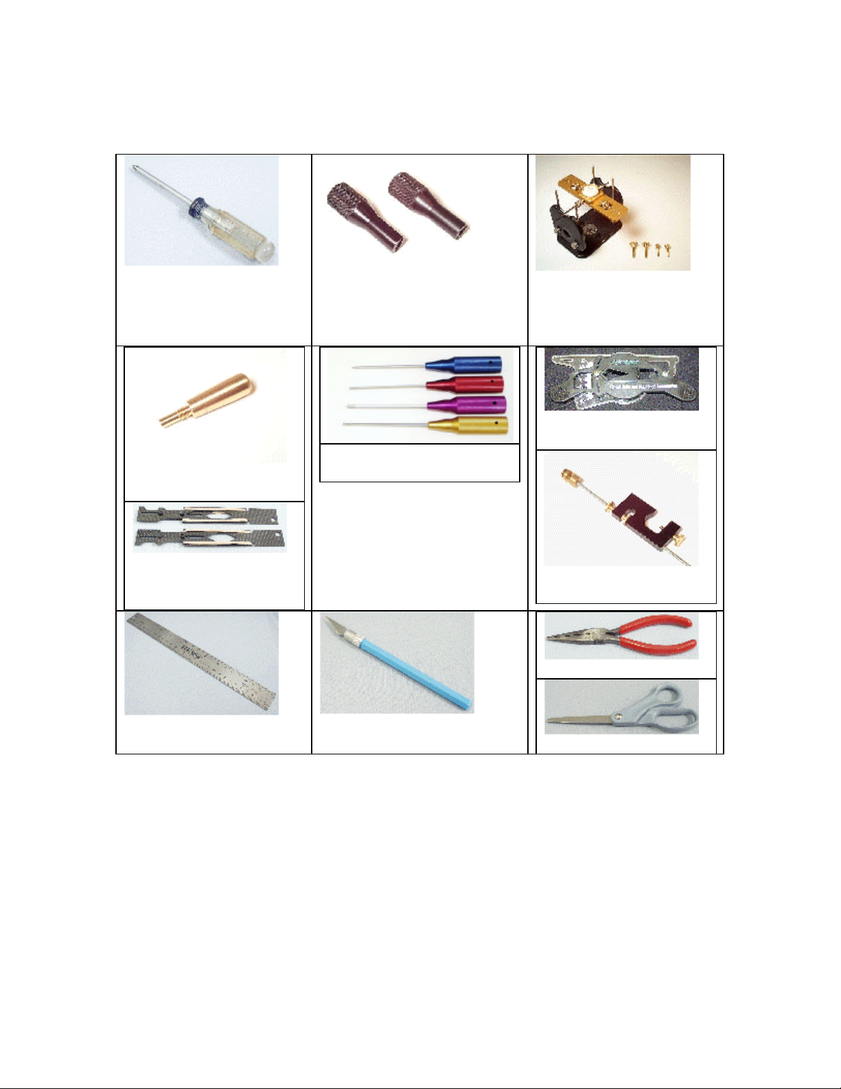
Tools Needed to Assemble the “Quick Learner”
Phillips Screw Driver
Piston Head Lock
HHI7020
Composite Paddle
Gauges
HHI7000
Ball End Drivers
HHI7050
Bubble Blade Balancer
HHI7010
High Point Balancer
DUB499
Pitch Gauge
HHI7320 – 6pc Nut &
Allen Driver Set
HHI7001
Universal FlybarLock
HHI7040
Ruler
Needle Nose Pliers
Hobby Knife
Scissors
Page 5
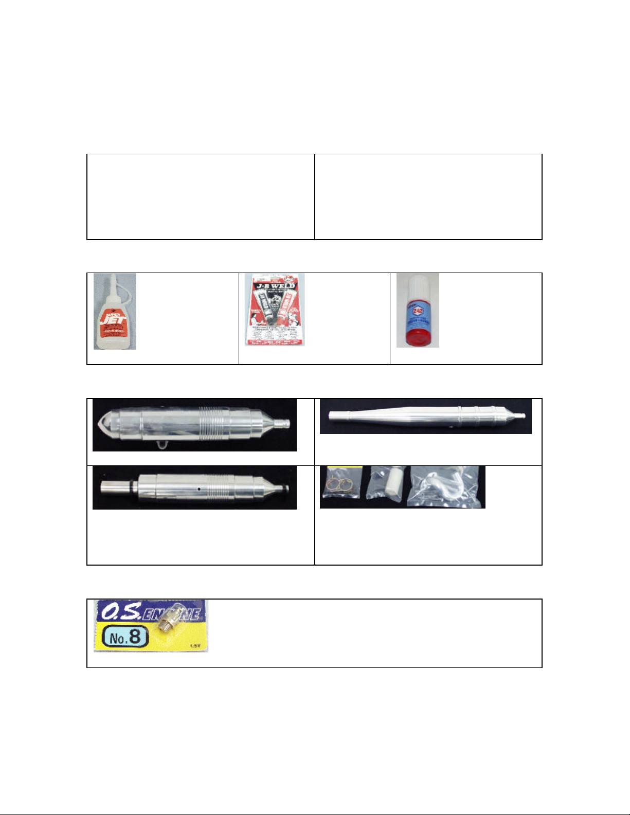
Hardware & Accessories
Engines (These are our Recommended Motor but others will work)
OS.15 CV-A
Glues & Thread Lockers
Ca Glue. …GBG1
JB Weld…JBW8265S
Exhaust Systems
HHI 30 Size Tuned Muffler
HHI 30/46 Size Tuned Heli-Pipe
Glow Plugs
Locktite. …….PT40
HHI 30 Size Long Tuned Pipe
Tuned Pipe Accessories
Rear Facing Exhaust Header
Exhaust Coupler
Exhaust Coupler Clamps
OS #8 Glow Plug. …OSMG2691
Page 6
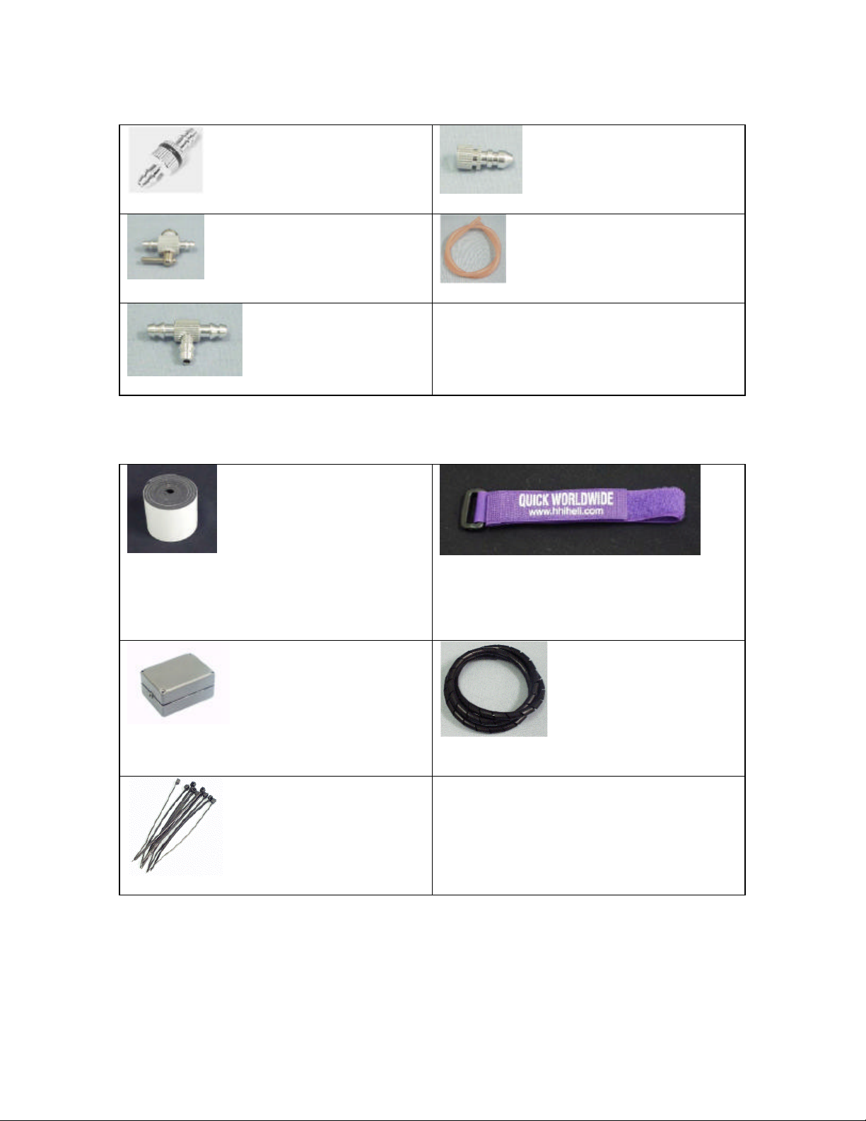
Fuel System Accessories
Fuel Filter… QUI9002
Mini Cock Straight… TET4321
Triangle Joint. …. TET4301
Radio Mounting Accessories
Single Sided Foam Tape… HHI2008
Tube Ends…. QUI9001
Fuel Tubing…. PRA7092
Receiver Hold Down Straps
HHI55** $4.99
2 Per Bag & Colors: Red, White,
Purple, Black
Receiver Strong Box… HHI2200
Wire Ties…HHIWT01
Spiral Wrap
HHI2809 & HHI2810
Page 7
Other Optional Accessories
Landing Gear Dampeners…HHI2004
60Size Skid Stops
HHI200*
Available in many Colors
See website or Call for Detail
3mm Finishing Caps
HHIM1110
Available in Blue, Silver, Gold, & Purple
3mm Fly-bar Stiffeners…HHI402*
Quick Learner Servo Arm Set
Base Load Antenna
HHI53**
Available in Blue, Gold, Purple
& In 40, 50, 72mhz
Page 8

acceptable performance. You should be sure to use all the same type of servo on the swash
which can lead to a crash. Also, be sure to check your bolts’ tightness after each flight. Many
Radio Requirements
Radios:
Hobbies & Helis & its distributors carry various lines of helicopter radios. Any radio that
supports EMS/CCPM Mixing will work fine. We recommend using an eight-channel or better
radio, although a six channel radio is all that is required.
Servos:
This is the single most important function of the helicopter. Any sport servo will offer
plate. Higher speed servo is recommended for tail, but not required.
Introduction:
Please read through the entire manual before starting your construction of the Quickie. If
there are any questions or concerns regarding the assembly of the helicopter you can call
Hobbies & Helis International (610)-282-4811 or Email the any of the following techs.
Technical Support Personnel:
Jon – Jon@ewtech.com
ET – et@ewtech.com
Threadlocker Warning (Very Important):
This is a general warning about the use of threadlocker and its importance. Threadlocker
must be used anywhere that a metal fastener i.e. (M2, M3, M4 Cap Head Bolts, Set Screws
etc.) are threaded into a metal part i.e. (Bearing Blocks, Cross-members, etc.). The failure to
use threadlocker can result in parts falling a part and possible loss of control of the model,
bolts, even with the use of threadlocker can come loose from vibration in the helicopter.
Page 9
Section 1 – Upper Frame Assembly
Parts List
Bag 1
Main-shaft Bearing Block X 2
M3x10 Self Tapping Screws x 16
M3x6 x 12
Radio Tray x 1
Lower Frame x 1
Rubber U-Channel x 2
Fuel Tank x 1
32mm Canopy Standoffs x 4
24mm Cr oss members x 2
Anti-rotation Guide x 1
Boom Halves x 2
M3x35 Cap Head Bolts x 4
M3 Locknut x 4
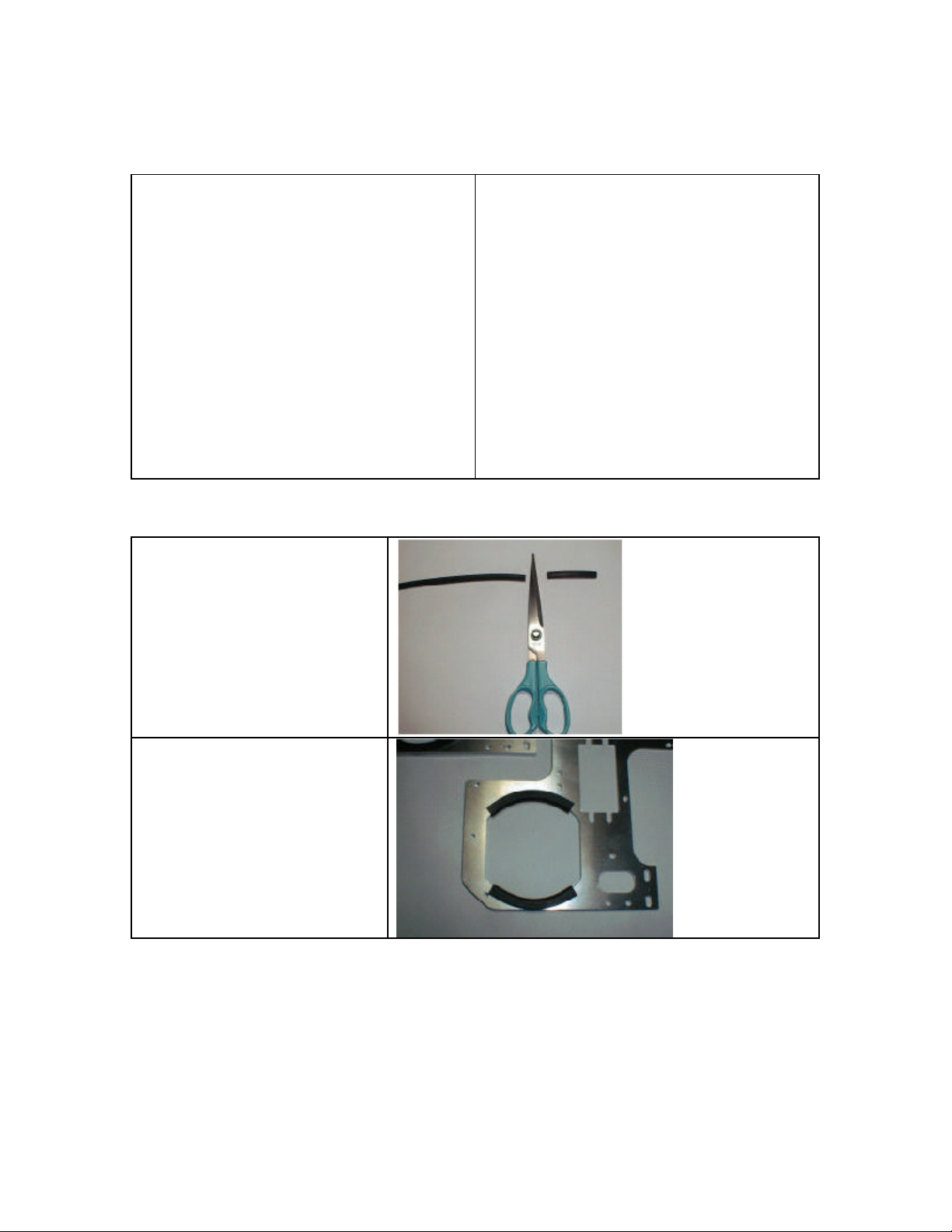
Cut the rubber U-channel to
55mm in length.
Frame Set Bag
Main Frames X 2
Locate the two main frames.
Install the rubber u-channel
onto both frame halves.
Page 10
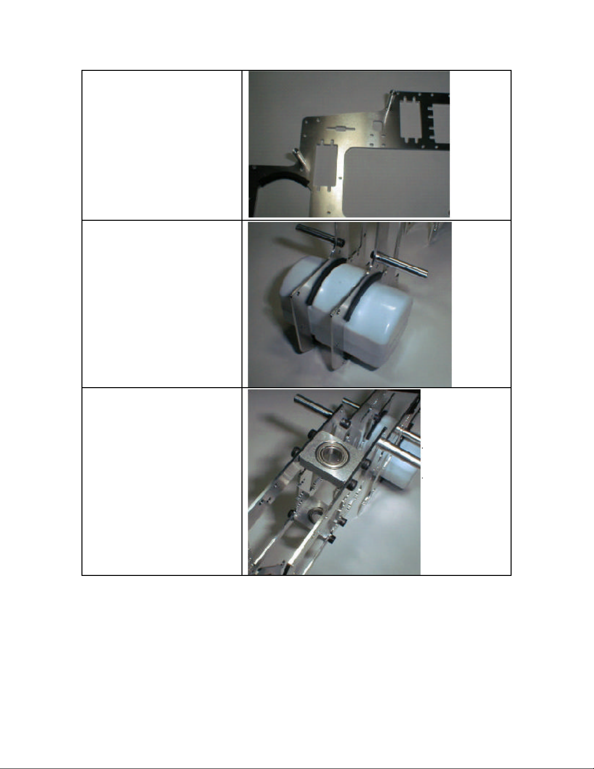
Install four canopy standoffs
(32mm) onto the two frame
halves.
Slide two frame halves over
fuel tank with canopy mounts
facing outward. The fuel tank
is on the front of the helicopter,
so looking from behind the
helicopter the open hole on the
tank goes out to the left.
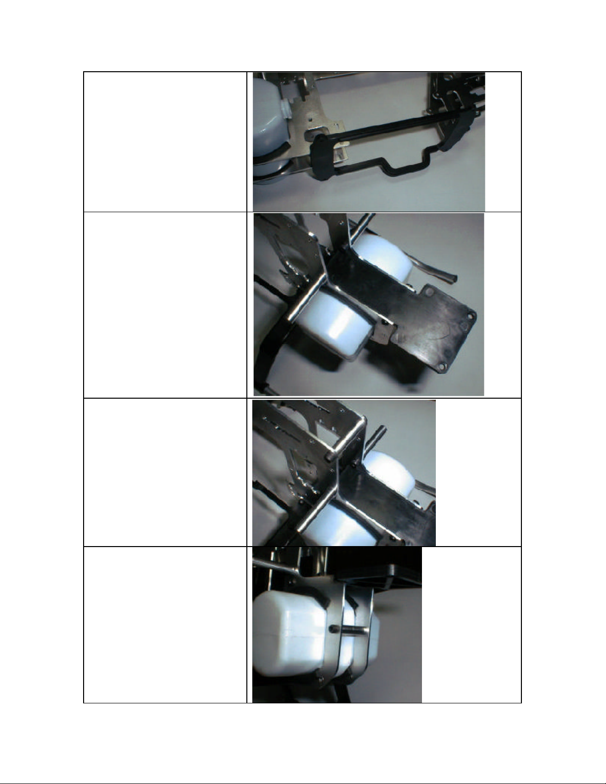
Install upper and lower main
shaft bearing blocks using (8)
M3x6 cap head screws. Note:
Be sure that on the upper
bearing block the open half
faces up. The lower block the
open face should be down.
Page 11
Install the lower frame stiffener
using (8) M3x10 Self tapping
screws.
Install the front radio tray using
(4) M3x10 self tapping screws.
Install (1) 24mm cross member
using (2) M3x6 cap head
screws.
Install (1) 24mm cross member
using (2) M3x6 cap head
screws.
Page 12

Install the anti-rotation guide
using (4) M3x10 self tapping
screws.
Install two boom halves using
(4) M3x35 cap head screws,
and (4) M3 locknuts.
Section 2 –Landing Gear Installation
Parts List
Bag 2
Landing Gear Struts X 2
Landing Gear Skids X 2
Landing Gear Skid Ends X 4
M3x3 Set Screws x 4
M3x14 cap head screws x 4
M3 locknuts x 4
Page 13

Locate (2) Landing Gear Struts place
a piece of masking tape across top
and Center helicopter on the struts
and mark holes
Replacement Part #:
Landing Gear Set – HHI4007
Drill (4) M3 holes at the previously
determined locations. After holes
have been Drilled remove tape.
Attach the landing gear to the lower
frame using (4) M3x14 cap head bolt.
Secure the bolts using the (4) M3
locknuts.
Page 14

Install (2) Skid Pipes into the struts so
the Helicopter is adequately balanced
and secure using (4) M3 Set Screws.
Install (4) Skid pipe end caps using
medium CA glue.
Bag 3 – Clutch bell Assembly, Counter Gear Assembly, and Main Gear Assembly.
Clutch Bell
Clutch Lining
Start Shaft
Cross Pin
Start Shaft Bearing Block
Hex Start Coupler
M4x4 Set Screw x 1
M3x8 Cap Head Screw x 8
Main Gear
Main Gear Hub
M3x6 Cap Head Screws x 4
Main Shaft
M3x18 Cap Head Screw x 1
M3 Locknut x 1
Main Shaft Collar
M3x3 Set Screws x 4
Counter Gear
Counter Gear Shaft
Lock Pin
E-Clip
Counter Gear Bearing Block x 2
Pulley Gear
Pulley Gear Plate
Lock Pin
E-Clip
M3x8 Cap Head Scre w x 8
Locate the Clutch Bell.
Page 15

Score the clutch bell as shown.
This provides better adhesion
from the liner to the bell.
Locate the lining and cut it to
98mm. Glue this in place with JB
Weld. The best way we to hold
the clutch liner to the be ll is to
wrap the clutch with a few rounds
of electrical tape and slide that
into the bell.
After the clutch bell is dry move
onto the next step. Slide the lock
pin through the start shaft.
Slide the start shaft into the bell
as shown to the left.
Page 16

Next, slide the start shaft bearing
block onto the clutch bell and
start shaft.
Slide the start coupler over the
top of the start shaft and secure it
to the index mark. That means
make sure the set screw hits the
flat on the shaft.
Note: There should be no up or
down play in the clutch bell once
the start coupler is fastened to the
Start Shaft.
Install the clutch bell assembly
into the helicopter and attach it
using (8) M3x8 cap head screws.
This unit will need to be adjusted
later, so only put them in loosely.
Attach the main gear to the main
gear hub using (4) M3x6 cap head
screws.
Page 17

Slide the main shaft through the
two main shaft bearing blocks.
The end with the hole closer to
the end should go down through
the blocks from the top side first.
The main shaft will slide through
the main gear assembly. Lock the
bolt in place using a M3x18 and a
M3 Locknut
Next slide the main shaft collar
over the main shaft and secure it
with (4) M3x3 set screws. Be
sure there is no up and down play
in the mainshaft after the collar is
secured.
Install the steel stopper pin into
the counter gear shaft. Then slide
the counter gear onto the counter
gear shaft.
Page 18

Secure the gear in place using the
provided E-clip.
Locate the two counter gear
bearing blocks. Next slide each
bearing block onto the counter
gear shaft. Each bearing block
has an open face. The open faces
should in toward the gear.
Then slide the pulley spacer on,
and finally the cross locking pin.
Next slide the gear on the shaft
capturing the cross pin with the
slot in the gear. Secure the gear
down with the second e-clip.
Section 4 –Fan Shroud
Parts List
Fan Shroud x 1
M3x10 Self tapping screws x 4
Attach the counter gear assembly
to the frame using (8) M3x8 cap
head screws.
Page 19

Section 5 – Clutch Assembly
Parts List
Fan Hub
Fan
M3x6 Flat head screws x 4
Clutch
M3x8 x 2
Install the fan shroud using (4) M3x10
self tapping screws.
Motor Mount
M3x10 x 4
M2x8 x 1
Shim Ball x 1
M3x6 Cap head screw x 4
Attach the fan to the fan hub using
(4) M3x6 flat head screws.
Install the fan hub onto the crank
shaft and secure it in place using the
nut provided with the engine. Be
sure to use red threadlocker to ensure
the nut does not come loose.
Page 20

Attach the clutch to the fan hub using
(2) M3x8 cap head screw.
Attach the motor mount to the motor
using (4) M3x10.
Attach the shim ball to the throttle
arm using a M2x8 screw.
Parts List
Swashplate
Washout Arms
Washout Base
Slide the engine up into place and
secure it using (4) M3x6 cap head
screws.
Section 6 – Control Items
M2x12 Pan head screw x 2
M3x3 Set Screw x 1
M3x6 Pivot studs x 2
Page 21

Antirotation guide pin
Washout link x 2
M3x10 Cap head screws
M3x5x1 Spacer x 2
Locate swashplate and slide it on the
main shaft first.
Next locate the washout base, arms,
links, M3x6 pivot studs, M3x10 cap
head screws, M3x5x1 spacers, and
M2x12 pan head screws. First slide an
M3x8 cap head screw through each
arm. Note which direction the screw
should go through the arm in the
picture. Slide an M3x5x1 on each bolt
and attach them to the base. Next
attach an M3x6 pivot stud to each of
the washout arms. Finally attach a
washout link to each arm with an
M2x12 pan head screw. Next slide the
washout onto the main shaft with the
protruding side going down first.
Attach the washout links to the pivot
studs on the inner ring of the
swashplate.
Slide the Antirotation guide pin on the
main shaft next. Secure it using the
M3x3 set screw. This will be adjusted
later, so snug is all this screw needs to
be for now.
Page 22

Section 7 – Head Assembly
Parts List
Center Hub
Seesaw
Seesaw Collar x 2
M3x8 Cap head screw x 2
M3x6 Pivot studs x 2
M3x16 Cap head bolt
M3 Locknut
7x13x3 O-ring x 2
O-ring spacer x 2
Spindle
5x10x4R Bearing x 4
M3x10 Cap head screw
3x8x1 Washer x 2
Hiller arm x 2
M3x10 Cap head screw x 2
3x5x1 Spacer
Flybar
Flybar control arm base x 2
Flybar control arm extension x 2
Flybar control arm spacer (3x5x5) x 2
M4x4 Set screw x 2
M3x8 Cap head screw x 2
Flybar paddle x 2
Blade Grip x 2
M3x22 Cap head bolt x 2
M3 Locknut x 2
Locate the head block, seesaw, seesaw
collars, and (2) M3x8 cap head screws.
Slide the seesaw into the opening on
the head block. Slide a seesaw collar
into each of the bushings on the head
block. Secure the seesaw using the (2)
M3x8 cap head screws.
Locate (2) M3x6 pivot studs. Install
the two pivot studs into the seesaw.
They should be in holes opposite of
each other. The other two holes tapped
in the seesaw will be unused.
Attach the head block to the main shaft
using the M3x16 cap head bolt and an
M3 locknut.
Page 23

Install two 7x13x3 o-rings into the
head block. Next slide the head
spindle through the o-rings. Then slide
the head dampener spacers onto the
spindle
Each blade grip will have (2) 5x10x4R
bearings. Install the bearings into the
blade grips. Slide each one onto the
spindle shaft. Secure the blade grips to
the spindle using (2) M3x10 cap head
screws. Place a 3x8x1 spacer under
each bolt before installing them.
Attach each hiller arm to the blade grip
using an M3x10 cap head screw. Put
the bolt through the hiller arm and put
a 3x5x1 spacer on the bolt next, and
screw it into the blade grip.
Slide the flybar through the seesaw.
Page 24

Locate two 3x5x5 spacers, two flybar
control arm bases, two flybar control
arm extensions, and two M4x4 set
screws. Slide (2) 3x5x5 spacers onto
the flybar with the protruding side
going against the seesaw. Next slide
the flybar control arm bases onto the
flybar. They face in opposite
directions and oppose the M3x6 pivot
studs on the seesaw previously
installed. Secure them with (2) M3x5
set screws. Be sure that they are
parallel with each other and that the
flybar is equally distant from both
ends.
Attach the (2) flybar control arm
extensions using (2) M3x8 cap head
screws.
Screw each paddle onto the flybar
25mm. Be sure the paddles are parallel
with each other. Also the paddles
should be inline/parallel with the flybar
control arms.
Use M3x22 cap head bolts with M3
locknuts to attach each blade to the
grip.
Page 25

Section 8 – Tail Assembly
Parts List
Tail boom
Belt
Boom holder half x 2
M3x35 x 4
M3 Locknut x 4
Tail output shaft
Pulley gear
M3 set screw x 2
Tail case side plate x 2
5x10x4R Bearing x 2
Tail pitch lever base
M2x6 Pan head screw x 2
M3x6 Cap head screw x 6
Tail Pitch Slider
M3x4 Pivot Stud
2.3 Medium ball ends
Tail Pitch Lever
M3x4 Pivot stud
M3x10 Cap head screw
M3x3 Set screw
Tail rotor hub
Tail blade grips x 2
3x7x3R Bearing x 2
M3x6 cap head screw x 2
M2x8 Pan head screw x 2
Shim ball x 2
Tail blades x 2
M3x20 Cap head screw x 2
M3 Locknut x 2
Tail blade spacers x 4
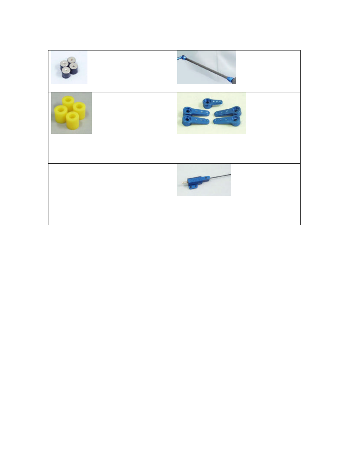
Locate the tail boom and the belt.
Slide the belt through the boom. Be
sure you do not twist the belt.
Install the two boom halves into the
frames. Put the (4) M3x35 cap head
screws through the four open holes in
the boom halves. Loosely put the nuts
on the ends of the bolts.
Page 26

Locate your tail output shaft and tail
pulley gear. Secure the gear to the
shaft using (2) M3x3 set screw.
Locate your two tail case side plates.
Install a 5x10x4R Bearing into each
plate.
Attach the tail pitch lever mount to the
side plate using (2) M2x6 pan head
screws.
Attach the side plate to the boom
using two M3x6 cap head screws.
Next slide your tail output and shaft
through the side plate.
Attach the other tail case side plate to
the tail boom using (2) M3x6 cap head
screws. Also attach the tail case cross
member using (2) M3x6 cap head
screws.
Locate your tail pitch slider, (2)
medium ball ends, and an M3 x4 pivot
stud.
Page 27

Slide the tail pitch slider assembly
onto the tail output shaft.
Attach the M3x4 pivot stud to the tail
pitch lever.
Attach the tail pitch lever to the tail
pitch lever base using an M3x10 cap
head screw. Be sure that you capture
the M3x4 pivot stud in the tail pitch
slider with the brass coupler in the tail
pitch lever.
Attach the tail rotor hub to the tail
output shaft using an M3x3 set screw.
Install a 3x7x3R bearing into each tail
blade grip. Then attach each grip to
the tail rotor hub using an M3x6 cap
head screw.
Install a shim ball onto each blade grip
using an M2x8 pan head screw. They
should go in the outmost holes.
Page 28

Attach a tail blade to each grip using
(2) tail blade spacers, an M3x20 cap
head bolt, and an M3 locknut.
Note: The Tail Blades should rotate
counter clockwise when looking at the
right side of the Tail Case.
Section 9 – Fin Set Installation & Fuel Tank Assembly
Parts List
Vertical Fin
Horizontal Fin
C-clamp x 2
M3x14 Cap head screw x 4
Fuel tank outer plate
Fuel tank inner plate
2.6 Screw
Fuel tank tubing x 2
Clunk
Attach the horizontal fin using
one c-clamp and (2) M3x14
cap head screws.
Note: Be sure the fin doesn’t
interfere with the tail blades
when they are rotating.
Page 29

Attach the vertical fin using
one c-clamp and (2) M3x14
cap head screws.
Section 10 – Linkage Rod Installation
Parts List
M2x8 Pan head screws x 8
Shim ball x 8
M2.3x35mm Linkage Rod x 2
M2.3x50mm Linkage Rod x 4
M2.3x20mm Linkage Rod x 2
2.3mm Ball end, Medium x 8
Tail Rotor Pushrod guide set. (Clips,
two inner sleeves (2))
Attach each servo using (4) M3x14 Cap head screws and (4) M3 Locknuts. Look at the
pictures that follow for the proper servo orientation.
2.3mm Ball end, Long x 10
Double Link x 2
Canopy
Rubber grommets x 4
M3x14
Cap head screws x 4
Stainless rudder control rod end x 2
M3x14 Cap head screw x 40
M3 Locknut x 40
Page 30

Step 1 – Linkage Rod Setup
In the following table the linkages will
be measured center to center as per
the picture. The table explains the
amount of rods you need to make and
which ball links to use on each end.
This will get the helicopter close to
finished setup, as always you will need
to make some final adjustments to
maximize the performance of your
Helicopter
Replacement Part #:
Linkage Rod Set – QC150
All Linkages available individually just
know the size
Step 1A – Shim Ball Installation
Install (8) Shim Balls using (8) M2-8
Phillips Screws. Install each Shim ball
as close to the recommended distance
for the center of the servo splice and
the center of the shim balls.
Carburetor 11.75-13mm
Throttle Servo 11.75-13mm
Swashplate
18-20mm
Servos
Rudder Servo 11.75-13mm
Rod Use
# of Rods
Rod Size
Ball Link 1
Ball Link 2
Center to
Center
Elevator Servo
to Swashplate
1
2.3-35
Medium
Medium
53mm
Page 31

Rod Use
# of Rods
Rod Size
Ball Link 1
Ball Link 2
Center to
Center
Rod Use
# of Rods
Rod Size
Ball Link 1
Ball Link 2
Center to
Center
Upper Swash
Servo to
Swashplate
1
2.3-35
Medium
Medium
55mm
Lower Swash
Servo to
Swashplate
1
2.3-50
Long
Long
77mm
Rod Use
# of Rods
Rod Size
Ball Link 1
Ball Link 2
Center to
Center
Throttle to
Carburetor
1
2.3-50
Long
Long
78mm
Page 32

Washout to
Flybar Control
Rod Use
# of Rods
Rod Size
Ball Link 1
Ball Link 2
Center to
Center
Arm
1
2.3-20
Medium
Medium
38mm
Seesaw to Hiller Arm
Use a double link on this spot.
Assemble the push rod guides.
There are three pieces the main
clip and two inner sleeves.
Simply slide the two sleeves
into each other and then into the
main clip and glue. Putting
electrical tape onto the boom
before gluing is good, so it is
possible to reuse the clip later.
(HHI2900 – Rod Guides)
Page 33

Install the carbon rudder control
rod. The rod should end up 22”
or 558mm long from ball to
ball. Slide the carbon rod
through the guides and glue the
ends on. Screw the links onto
the ends and attach to the balls.
Rod Use
# of Rods
Rod Size
Ball Link 1
Ball Link 2
Center to
Center
Swashplate to
Hiller arm
2
2.3-50
Long
Long
83mm
Page 34

Place the canopy where you
like, mark the holes for the
canopy standoffs. Use a ¼”
drill bit. Place the grommets in
the holes and secure the canopy
to the helicopter using (4)
M3x14 cap head screws.
Radio Setup
General Information:
First, change your radio to 3 Point, 120 Degrees swash-plate mixing. My advice
is to read your radio manual for proper adjustment of the swash mixing. After you
have the radio gear installed, the basic guidelines for proper setup of an EMS
system is everything must be 90 Degrees and Parallel with all control sticks in
the center. After all linkages are installed and everything meets the above
requirements, you should have 0 degrees of main rotor blade pitch at center
stick. Make the necessary adjustment to complete the setup.
Pitch Curve Setup:
Complete the following steps in the Pitch Curve Menu of the Radio. In
Normal Mode make the Pitch curve the following: at Bottom-Stick,
0 to -2 Degrees; Mid-Stick, 5 to 6 Degrees, and Top-Stick, 9 to 10 Degrees.
For Stunt 1 & 2: Bottom-Stick, -9 Degrees; Mid-Stick, 0 Degrees; and
Top-Stick, 9 Degrees. Note: Stunt one; two should only be used by pilots, ready
for forward flight and aerobatics. Do not use these settings until your skill level is
ready.
Page 35

so you have plenty of pin left at full negative.
Once you have the rotation and the
Throttle Curve Setup:
Normal Mode, Bottom -Stick 20 Percent throttle;
Mid-Stick, 50 Percent Throttle, Top Stick 100 Percent Throttle. Stunt
1 & 2 Bottom -Stick 100 Percent; Mid-Stick, 35 Percent; Top Stick, 100
Percent.
Tail Rotor: Setup the Tail rotor limits so the throws that the tail pitch slider does
not exceed a 5mm gap between the tail case and the tail pitch slider.
Mechanical Setup
Servo Arm Length: Servo arm Length should be as close to the T-levers and
elevator control arm as possible. This will allow for best servo setup.
Orient the servo arms: With the collective stick is centered; ensure that the
head servo arms are perpendicular to their control rods. If they are not rotate
your arms to they are close and use your sub trims to fine-tune them.
Leveling the swash: Using a ruler measure from the bottom of the swash plate
to the top main shaft-bearing block. Adjust all the connecting rods so that the
swash plate is level. Equal all the way around the swash plate. Also Hobbies &
Helis makes a nice swash-leveling tool to make this task easy.
Level the washout and mixer arms: With the collective stick centered and the
fly-bar perpendicular to the main-shaft, ensure that th e washout and mixer arms
are perpendicular to the main-shaft. Adjust rods as necessary.
Additional tail rotor information: When you set up your tail rotor you need to make
sure that your tail pitch slider is not going to hit your tail pitch control lever mount.
With some gyros you can adjust this and others you can't. If you have a gyro that
you can't adjust this all you need to do is take a piece of fuel tubing and slide it
onto your tail output shaft. Spin your tail rotor to make sure the fuel tubing is l ong
enough but not too long.
Helicopter Center of Gravity (CG): When the fly-bar is perpendicular to the tail boom, pick it up and the nose should be just slightly heavier. If you need to just
move your battery forward to get proper CG.
Washout Anti-rotation Pin: Leave the pin relatively loose until you have your
radio equipment installed and your servos are operating correctly. Next, take
your washout link and line it up with the anti-rotation guide. Rotate the head so
that the main blades are parallel w ith the tail boom while the link is lined up. This
is where the pin should be rotation wise. Next, Cycle you swashplate all the way
to the top and tip it all the way in one direction. Rotate the head and make sure
the pin does not touch the swashplate at any point in the rotation. You should
have the pin so that it is just not touching, but you want the pin as low as possible
Page 36

height, just lock the pin down.
Engine Break-in: Be sure to break in the engine with a prop or loosen the glow
plug so not to break to start shaft. The 15 CV-A and car engines have very tight
compression.
 Loading...