

Page 1
REV 008
a
High
Quality
Nautical
Equipment
Manuale d'uso SALPA ANCORA VERTICALI
User's Manual VERTICAL WINDLASSES
DN4 DYLAN SERIES
DN4 1500 DC
DN4 1700 DC
DN4 2000 DC
DN4 3000 AC
DN4 HYDRO
IT
EN
Page 2

Page 3

3
DN4 1500/1700/2000/3000W HYDRO - IT EN - REV008A
Pag. 4 Caratteristiche tecniche
Pag. 5 Installazione
Pag. 6 Schema di collegamento DN4 DC
Pag. 7 Schema di collegamento DN4 3000W 230V AC
Pag. 8 Schema di collegamento DN4 3000W 400V AC
Pag. 9 Avvertenze importanti - Uso
Pag. 10/11 Manutenzione
Pag. 12 Salpa ancora idraulico: caratteristiche tecniche - Installazione
Pag. 13 Salpa ancora idraulico: schema di collegamento
Pag. 14/15 Ricambi
Pag. 16 Technical data
Pag. 17 Installation
Pag. 18 Connection diagram DN4 DC
Pag. 19 Connection diagram DN4 3000W 230V AC
Pag. 20 Connection diagram DN4 3000W 400V AC
Pag. 21 Warning - Usage
Pag. 22/23 Maintenance
Pag. 24 Hydraulic windlass: technical data - Installation
Pag. 25 Hydraulic windlass: connection diagram
Pag. 26/27 Spare parts
INDICE
INDEX
IT
GB
Page 4
4
CARATTERISTICHE TECNICHE
IT
DN4 1500/1700/2000/3000W HYDRO - IT EN - REV008A
Quick® si riserva il diritto di apportare modifiche alle caratteristiche tecniche dell'apparecchio e al contenuto di questo manuale senza alcun preavviso.
In caso di discordanze o eventuali errori tra il testo tradotto e quello originario in italiano, fare riferimento al testo italiano o inglese.
F
a
a b c d a b c d
a
a
a
a
a
a
a
1° ESEMPIO:
DN4 1512D
2° ESEMPIO:
DN4 2024
DN4 15 12 D DN4 20 24
-
Nome della serie:
[ DN4 ] =
base in acciaio inox AISI 316 e
alluminio anodizzato in ossido duro
Potenza motore:
[ 15 ] = 1500 W
[ 17 ] = 1700 W
[ 20 ] = 2000 W
[ 30 ] = 3000 W
Tensione alimentazione motore:
[ 12 ] = 12 V
[ 24 ] = 24 V
[ TR ] = 230 V / 400 V
Campana:
[ D ] =
con campana
[ - ] = senza campana
(1) Dopo un primo periodo d’uso.
(2) Misure effettuate con barbotin per catena da 12/13 mm.
(3) Valore minimo consigliato per una lunghezza totale L<20m. Calcolare la sezione in funzione della lunghezza del collegamento.
(4) Con interruttore specifico per correnti continue (DC) e ritardato (magneto-termico o magneto-idraulico).
(5) Su richiesta possono essere forniti alberi e prigionieri per spessori di coperta maggiori.
a b c d
(*) I valori indicati in tabella si riferiscono ad una combinazione cima e catena secondo il sistema Quick®, non garantiamo il corretto funzionamento con
altri tipi di anchor-rode.
BARBOTIN
10 mm - 3/8” 12/13 mm
Catena supportata
10 mm 10 mm 3/8” 3/8” 13 mm 12 mm 7/16”
DIN 766 ISO G4 BBB DIN 766 ISO G4
Cima supportata (*) 5/8” (15,8 mm) - 3/4” (19 mm) 3/4” (19 mm)
Dimensioni dei modelli a pagina 28/29
MODELLI DN4 - / D
POTENZA MOTORE 1500 W 1700 W 2000 W
Tensione motore 12 V 12 V 24 V 24 V
Tiro istantaneo massimo 1100 Kg (2425.1 lb) 1150 Kg (2535.3 lb) 1200 Kg (2645.5 lb) 1600 Kg (3527.4 lb)
Carico di lavoro massimo 400 Kg (881.8 lb) 470 Kg (1036.2 lb) 570 Kg (1256.6 lb) 750 kg (1653.5 lb)
Carico di lavoro 135 Kg (297.6 lb) 155 kg (341.7 lb) 190 Kg (418.9 lb) 250 Kg (551.1 lb)
Assorbimento corrente al carico di lavoro (1) 150 A 170 A 95 A 105 A
Velocità massima di recupero (2) 35,2 m/min (115.5 ft/min) 33,5 m/min (109.9 ft/min) 39,0 m/min (128.0 ft/min) 35,0 m/min (114.8 ft/min)
Velocità di recupero al carico di lavoro (2) 19,0 m/min (62.3 ft/min) 16,2 m/min (53.1 ft/min) 20,8 m/min (68.2 ft/min) 22,3 m/min (73.2 ft/min)
Sezione minima cavi motore (3) 50 mm
2
(AWG0) 50 mm2 (AWG0) 25 mm2 (AWG3) 35 mm2 (AWG2)
Interruttore di protezione (4) 100 A 100 A 60 A 80 A
Spessore coperta (5)
25 ÷ 50 mm
(31/32” ÷ 1” 31/32)
30 ÷ 70 mm (1” 3/16” ÷ 2” 3/4)
Peso senza campana 23,7 Kg (52.2 lb) 25,6 Kg (56.4 lb) 25,6 kg (56.4 lb) 31,2 Kg (68.8 lb)
Peso con campana 25,0 Kg (55.1 lb) 26,9 Kg (59.3 lb) 26,9 kg (59.3 lb) 32,5 Kg (71.6 lb)
MODELLO DN4 AC - / D
POTENZA MOTORE 3000 W TR
Tensione motore 230/400 V
Tiro istantaneo massimo 2800 Kg (6172.9 lb)
Carico di lavoro massimo 930 Kg (1984.2 lb)
Velocità massima di recupero (2) 15,0 m/min (49.2 ft/min)
Spessore coperta (5) 30 ÷ 70 mm (1” 3/16” ÷ 2” 3/4)
Peso senza campana 38,0 kg (83.8 lb)
Peso con campana 40,0 kg (88.2 lb)
COME SI LEGGE IL MODELLO DEL SALPA ANCORA:
Page 5
5
INSTALLAZIONE
IT
DN4 1500/1700/2000/3000W HYDRO - IT EN - REV008A
ATTENZIONE:
prima di effettuare il collegamento accertarsi che non sia presente l'alimentazione su cavi.
PAINT
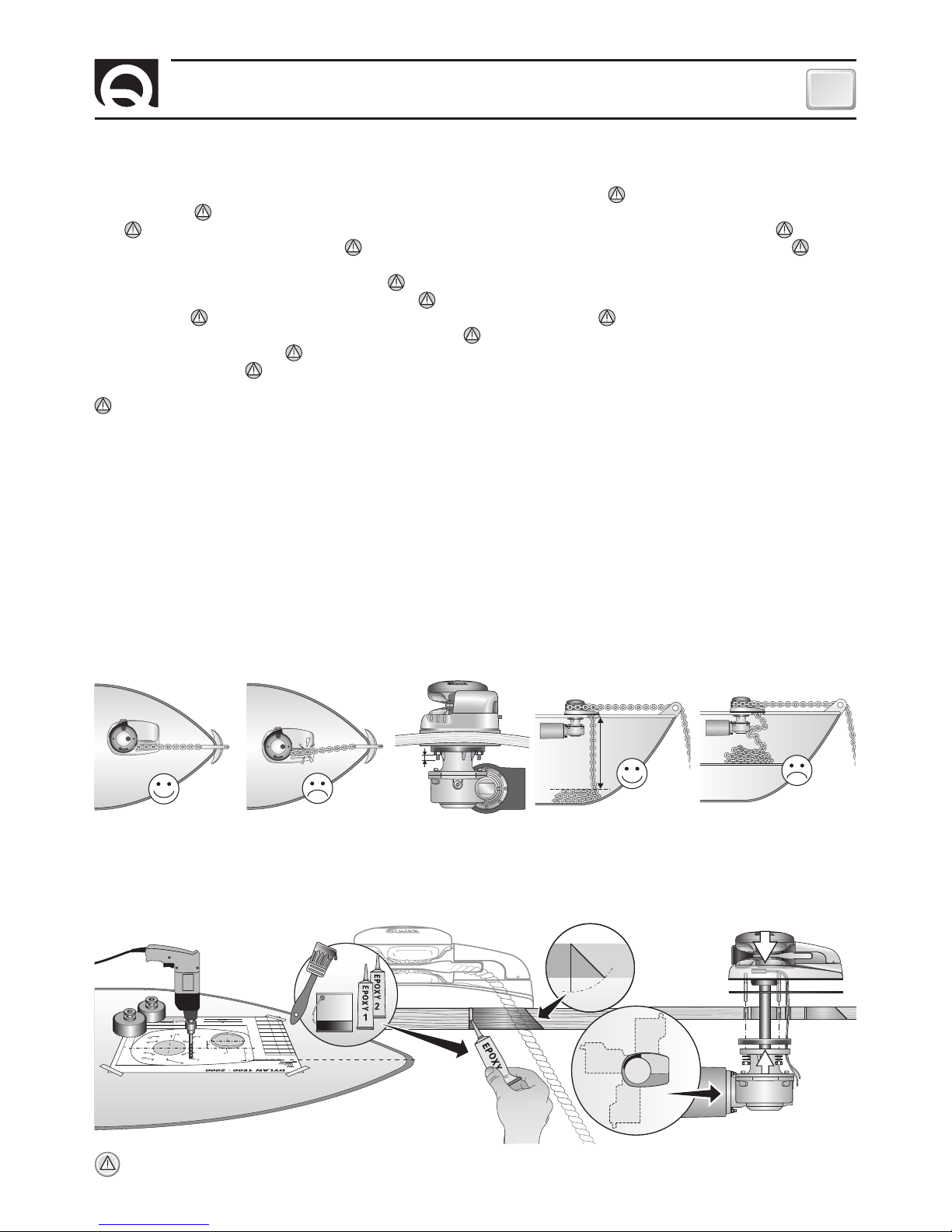
PROCEDURA DI MONTAGGIO:
stabilita la posizione ideale praticare i fori utilizzando la dima di foratura fornita a corredo. Rimuovere il materiale in eccesso dal foro di passaggio della catena/cima, rifinirlo e lisciarlo con un prodotto specifico (vernice marittima, gel o
resina epossidica) assicurando il libero passaggio della catena/cima. Posizionare la parte superiore, inserendo la guarnizione fra la coper
ta e la base e collegare a questa la parte inferiore, infilando l'albero nel riduttore. Fissare il salpa ancora avvitando i dadi sui prigionieri di
bloccaggio. Collegare i cavi di alimentazione provenienti dal salpa ancora al teleruttore.
40 cm (16”)
Max
5 mm
(3/16”)
45°
90°
90°
90°
PRIMA DI UTILIZZARE IL SALPA ANCORA LEGGERE ATTENTAMENTE IL PRESENTE MANUALE D'USO.
IN CASO DI DUBBI CONSULTARE IL RIVENDITORE QUICK
®
.
ATTENZIONE:
i salpa ancora Quick® sono stati progettati e realizzati per salpare l'ancora. Non utilizzare questi apparecchi per altri
tipi di operazioni.
Quick® non si assume alcuna responsabilità per i danni diretti o indiretti causati da un uso improprio dell'apparecchio. Il salpa ancora non è progettato per sostenere carichi generati in particolari condizioni atmosferiche (burrasca). Disattivare
sempre il salpa ancora quando non è in uso.
Accertarsi che non vi siano bagnanti nelle vicinanze prima di calare l’ancora. La giunzione tra la cima e la catena deve avere dimensioni ridotte per poter scorrere agevolmente dentro la sagoma del barbotin. Per qualsiasi
problema o richiesta contattare l’assistenza Quick
®
. Per maggiore sicurezza, nel caso in cui uno si danneggi suggeriamo di installare
almeno due comandi per l’azionamento del salpa ancora.
Consigliamo l’uso dell’interruttore magneto-idraulico Quick® come sicurezza per il motore. Bloccare la catena con un fermo prima di partire per la navigazione. La scatola teleruttori o teleinvertitori deve
essere installata in un luogo protetto da possibili entrate d’acqua.
Dopo aver completato l’ancoraggio, fissare la catena o cima a punti fissi quali chian stopper o bitta. Per prevenire rilasci non voluti l’ancora deve essere fissata, il salpa ancora non deve essere usato
come unica presa di forza.
Isolare il salpa ancora dall’impianto elettrico durante la navigazione (disinserire l’interruttore di protezione
del motore) e bloccare la catena ad un punto fisso dell’imbarcazione.
Non deve essere presente materiale infiammabile nel gavone o nella zona in cui è presente il motore del salpa ancora.
LA CONFEZIONE CONTIENE:
salpa ancora (top + motoriduttore) - cassetta teleruttori - guarnizione della base - dima di foratura -
leva - viterie (per l'assemblaggio) - manuale di istruzioni - condizioni di garanzia.
ATTREZZI NECESSARI PER L'INSTALLAZIONE:
trapano con punte: Ø 5 mm (3/16”), Ø 9 mm (23/64") e Ø 11 mm (7/16");
a tazza Ø 80 mm (3" 9/64); chiave esagonale: 13 mm.
ACCESSORI QUICK® CONSIGLIATI:
deviatore da pannello (mod. 800) - Pulsantiera stagna (mod. HRC 1002) - Pulsante a piede (mod.
900) - Interruttore magneto-idraulico - Conta catena per l'ancoraggio (mod. CHC 1102M e CHC 1202M) - Sistema di comando via radio
RRC (mod. R02, P02, H02).
REQUISITI PER L'INSTALLAZIONE:
il salpa ancora va posizionato allineando il barbotin con il puntale di prua. Verificare che le
superfici superiore e inferiore della coperta siano più parallele possibili; se ciò non dovesse accadere compensare opportunamente la
differenza (la mancanza di parallelismo potrebbe causare perdite di potenza del motore). Lo spessore di coperta dovrà essere compreso
fra i valori indicati in tabella. Se si avessero spessori differenti è necessario consultare il rivenditore Quick
®
. Non devono esistere ostacoli
sotto coperta per il passaggio di cavi, cima e catena, la poca profondità del gavone potrebbe provocare inceppamenti.
Page 6
6
IT
DN4 1500/1700/2000/3000W HYDRO - IT EN - REV008A
-
+
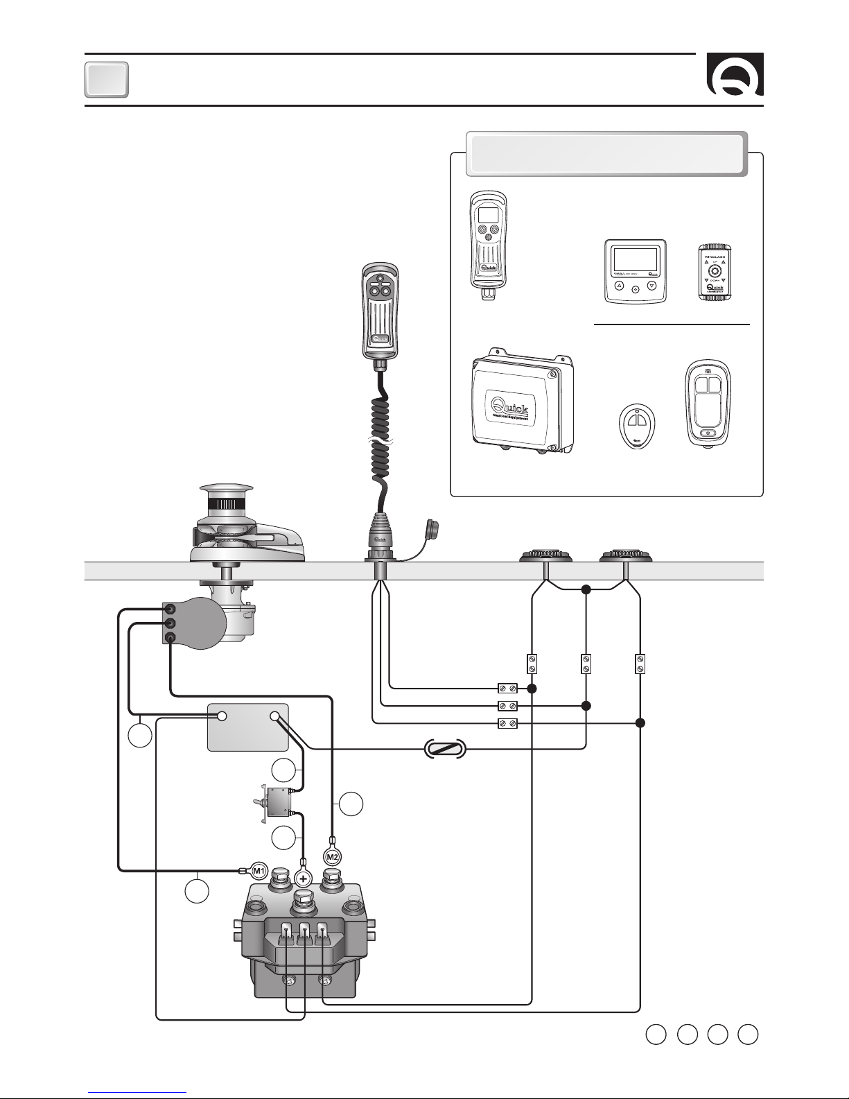
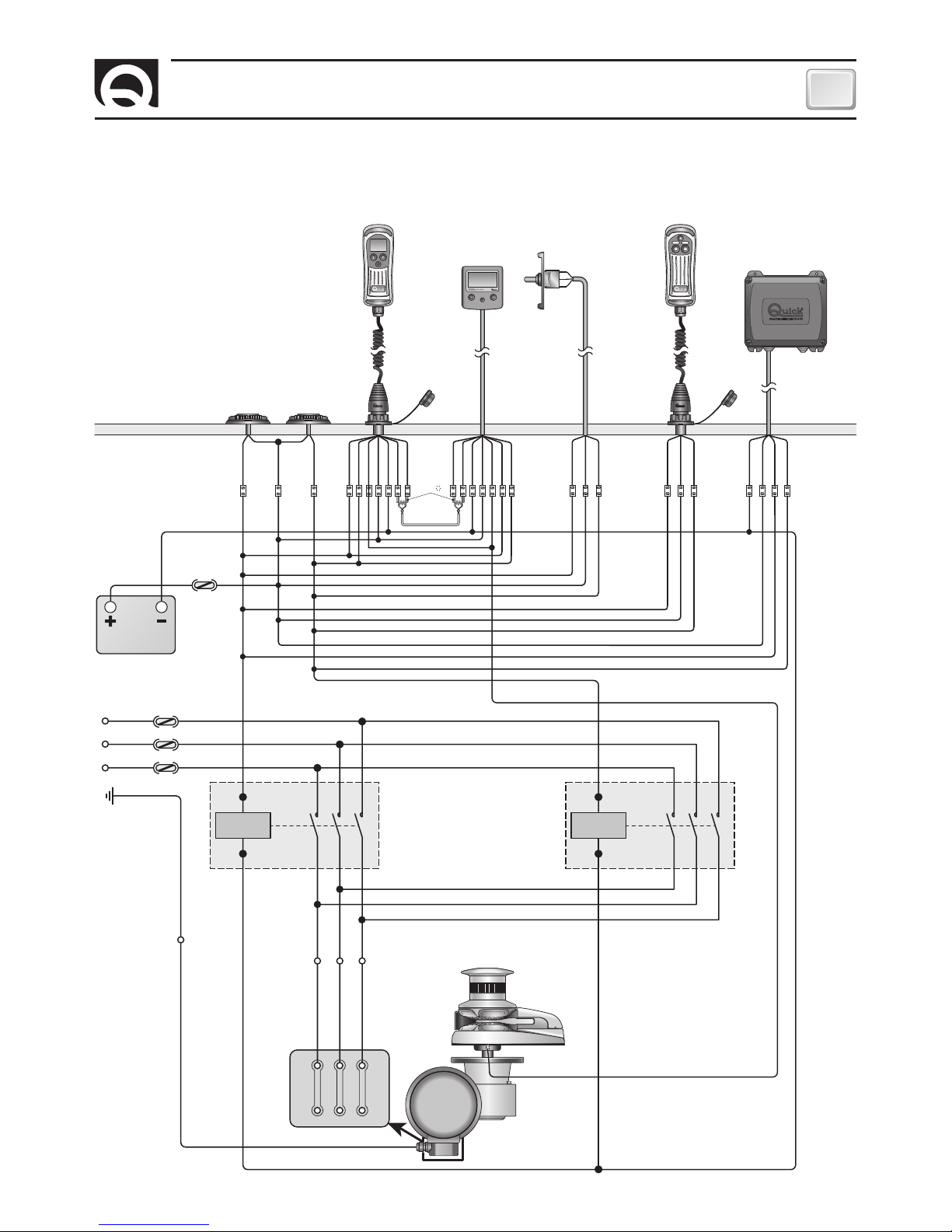
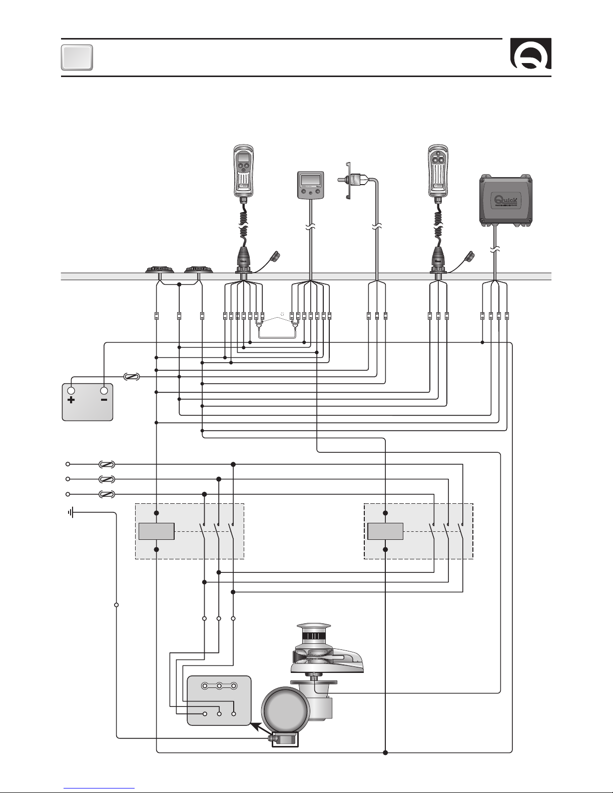
SISTEMA BASE DN4 DC
PULSANTIERA
MULTIUSO
MOD. HRC 1002
SALPA ANCORA
MOTORE
BATTERIA
INTERRUTTORE
MAGNETO
IDRAULICO
(VEDI TABELLA PAG.4)
CASSETTA
TELERUTTORI
MOD. T6315-12 (12V)
MOD. T6315-24 (24V)
C
A2
PULSANTI A PIEDE MOD. 900U E 900D
NERO
MARRONE
BLU
MARRONE
NERO
BLU
A1
FUSIBILE
4A (12V)
2A (24V)
L = L1 + L2 + L3 + L4
L4
L2
L3
L1
L3
SCHEMA DI COLLEGAMENTO
CONTACATENA
DA PANNELLO
CHC 1202 M
COMANDO
DA PLANCIA
MOD.800
PULSANTIERA
CONTACATENA
MOD. CHC 1002 M
ACCESSORI QUICK® PER L'AZIONAMENTO
DEL SALPA ANCORA
TRASMETTITORI
RADIOCOMANDI RRC
PULSANTIERA
MOD. H02
RICEVITORE
MOD. R02
TASCABILE
MOD. P02
Page 7
7
IT
DN4 1500/1700/2000/3000W HYDRO - IT EN - REV008A
24V
KM1
W2
U1
R
S
T
L1 XP
PE XP
R
V1 W1
U1
V1
W1
XP XP XP
U2 V2
U1 V1 W1
24V
KM2
FU1 13-25A aM
FU1 13-25A aM
L2 XP
S
FU1 13-25A aM
L3 XP
T
R S T
M
1
~
SISTEMA BASE DN4 3000W 230V AC
CONTACATENA A
PULSANTIERA
MOD. CHC1102 M
CONTACATENA PER
ANCORAGGIO
MOD. CHC1202 M
-
+
DOWN
UP
BLU
MARRONE
NERO
BLU
MARRONE
NERO
DOWN
SENSORE
UP
-
+
CAN H
CAN L
GRIGIO
ROSSO
VERDE
MARRONE
BIANCO
BLU
NERO
BLU
MARRONE
NERO
150
CAN H
CAN L
CAN H
CAN L
SALPA ANCORA
MOTORE
230V CA Max
3KW
MORSETTIERA
BATTERIA 24V
PULSANTIERA
MULTIUSO
MOD. HRC1002
RADIO RECEVITORE RRC
MOD. R02 (2CH)
COMANDO
DA PLANCIA
MOD. 800
MOD. 900/D
DOWN
PULSANTI A PIEDE
MOD. 900/U
UP
SCHEMA DI COLLEGAMENTO TRIFASE
SENSORE
Page 8
8
IT
DN4 1500/1700/2000/3000W HYDRO - IT EN - REV008A
SCHEMA DI COLLEGAMENTO TRIFASE
M
1
~
24V
KM1
W2
U1
R
S
T
L1 XP
PE XP
R
V1 W1
U1
V1
W1
XP XP XP
U2 V2
U1 V1 W1
24V
KM2
FU1 8 -16A aM
FU1 8 -16A aM
L2 XP
S
FU1 8 -16A aM
L3 XP
T
R S T
SISTEMA BASE DN4 3000W 400V AC
CONTACATENA A
PULSANTIERA
MOD. CHC1102 M
CONTACATENA PER
ANCORAGGIO
MOD. CHC1202 M
-
+
DOWN
UP
BLU
MARRONE
NERO
BLU
MARRONE
NERO
DOWN
SENSORE
UP
-
+
CAN H
CAN L
GRIGIO
ROSSO
VERDE
MARRONE
BIANCO
BLU
NERO
BLU
MARRONE
NERO
150
CAN H
CAN L
CAN H
CAN L
SALPA ANCORA
MOTORE
400V CA Max
3KW
MORSETTIERA
BATTERIA 24V
PULSANTIERA
MULTIUSO
MOD. HRC1002
RADIO RECEVITORE RRC
MOD. R02 (2CH)
COMANDO
DA PLANCIA
MOD. 800
MOD. 900/D
DOWN
PULSANTI A PIEDE
MOD. 900/U
UP
SENSORE
Page 9
9
IT
DN4 1500/1700/2000/3000W HYDRO - IT EN - REV008A
ATTENZIONE:
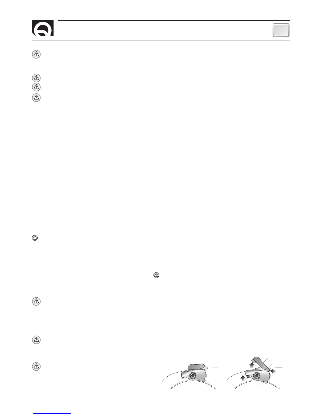
Prima di salpare l'ancora sbloccare il barbotin. Accertarsi che il comando (32/33), che attiva il blocco
sul barbotin, sia disattivato.
1) Sbloccare la sicurezza blocco barbotin (33).
2) Scorrere il comando blocco barbotin (32) verso poppa.
3) Inserimento automatico del blocco barbotin (31).
ATTENZIONE:
non avvicinare parti del corpo o oggetti alla zona in cui scorrono catena, cima e barbotin. Accertarsi che non sia
presente l'alimentazione al motore elettrico quando si opera manualmente sul salpa ancora (anche quando si utilizza la leva per allentare la frizione); infatti persone dotate di comando a distanza del salpa ancora (pulsantiera remota o radiocomando) potrebbero
accidentalmente attivarlo.
ATTENZIONE:
Bloccare la catena con un fermo prima di partire per la navigazione.
ATTENZIONE:
Non attivare elettricamente il salpa ancora con la leva inserita nella campana o nel coperchio del barbotin.
ATTENZIONE:
Quick® consiglia di utilizzare una protezione tipo fusibile/magnetotermico/magnetoidraulico di potenza adeguata a
seconda del motore utilizzato per salvaguardare il motore da surriscaldamenti o corto-circuiti. L’interruttore può essere utilizzato
per isolare il circuito di comando del salpa ancora evitando così azionamenti accidentali.
USO DELLA FRIZIONE
Il barbotin è reso solidale all'albero principale (19, 20, 21 o 22) dalla frizione (8 e 10). La frizione si apre (stacco) utilizzando la leva (1)
che inserita nella bussola (7) della campana o del coperchio barbotin (2), dovrà ruotare in senso antiorario. Ruotando in senso orario si
provocherà la chiusura (attacco) della frizione.
PER SALPARE
Accendere il motore dell'imbarcazione. Assicurarsi che la frizione sia serrata ed estrarre la leva. Premere il pulsante
UP del comando a vostra disposizione. Se il salpa ancora si arresta senza che l'interruttore magneto-idraulico (o magnetotermico) sia
scattato, attendere qualche secondo e riprovare (evitare una pressione continuata del pulsante). Se l'interruttore magneto-idraulico (o
magnetotermico) è scattato, riattivare l'interruttore e attendere qualche minuto prima di riprendere a salpare. Se, dopo ripetuti tentativi,
il salpa ancora continua a bloccarsi consigliamo di manovrare l'imbarcazione per disincagliare l'ancora. Controllare la salita degli ultimi
metri di catena per evitare danni alla prua.
PER CALARE
La calata dell'ancora si può effettuare tramite comandi elettrici oppure manualmente. Per effettuare l'operazione manualmente occorre aprire la frizione lasciando libero il barbotin di girare sul proprio asse e trascinare la catena o la cima in acqua. Per frenare la caduta dell'ancora bisogna ruotare la leva in senso orario. Per calare l'ancora elettricamente occorre premere il pulsante DOWN
del comando a vostra disposizione. In questo modo la calata è perfettamente controllabile e lo svolgimento della catena o della cima
è regolare. Per evitare sollecitazioni sul salpa ancora, una volta ancorati, bloccare la catena con un fermo oppure fissarla ad un punto
saldo con una cima.
RECUPERO MANUALE (versione senza campana)
Interrompere l'alimentazione elettrica del salpa ancora. Agire sul comando
(32/33) per attivare il blocco (31) sul barbotin (9); aprire la frizione (almeno due giri della bussola in senso antiorario), inserire la leva (1)
nell'apposita sede del coperchio barbotin (4) e recuperare manualmente la catena facendo ruotare la leva in senso orario. Terminata la
procedura di recupero manuale, rimuovere la leva dalla sua sede e inserirla nella bussola (2) per serrare la frizione.
Estrarre la leva (1) dal coperchio barbotin (4). Sbloccare il barbotin (9) agendo sulla leva di comando (32/33). Ripristinare l'alimenta-
zione elettrica del salpa ancora.
RECUPERO MANUALE (versione con campana)
Interrompere l'alimentazione elettrica del salpa ancora. Agire sul comando (32/33)
per attivare il blocco (31) sul barbotin (9). Con la leva (1) svitare completamente la bussola (7), estrarre la campana (6) e montare il recupero manuale (45) sul barbotin con le apposite viti (5). Inserire la leva (1) nell'apposita sede del recupero (45) e recuperare manualmente
la catena facendo ruotare la leva in senso orario. Terminata la procedura di recupero manuale, rimuovere la leva dalla sua sede, reinserire la campana e avvitare la bussola (7) per serrare la frizione. Estrarre la leva (1) dalla bussola (7). Sbloccare il barbotin (9) agendo
sulla leva di comando (32/33). Ripristinare l'alimentazione elettrica del salpa ancora.
USO DELLA CAMPANA
ATTENZIONE:
Prima di eseguire operazioni di tonneggio, accertarsi che l'ancora e relativa cima o catena siano fissate saldamente
ad una bitta o ad altro punto resistente dell'imbarcazione.
Per l'uso indipendente della campana (6), agire sul comando (32/33) per attivare il blocco (31) sul barbotin (9). Con la leva (1) aprire la
frizione (almeno due giri della bussola in senso antiorario). Rimuovere la leva dalla bussola (7), avvolgere la cima sulla campana in senso
antiorario (2 giri). Attivare il comando DOWN del salpa ancora mantenendo in tensione la cima durante il recupero. Variando questa
tensione in fase di recupero è possibile modificare la velocità di avvolgimento della cima.
ATTENZIONE:
durante il recupero, mantenere un'adeguata distanza di sicurezza tra mani e campana salpa ancora.
Terminata la procedura di recupero serrare la frizione stringendo la bussola del barbotin in senso orario e assicurare la cima ad
una bitta o ad altro punto resistente dell'imbarcazione.
BLOCCO DISINSERITO
BLOCCO INSERITO
AVVERTENZE IMPORTANTI - USO
1
2
3
33
32
31
Page 10
10
IT
DN4 1500/1700/2000/3000W HYDRO - IT EN - REV008A
ATTENZIONE:
accertarsi che non sia presente l'alimentazione al motore elettrico quando si opera manualmente sul salpa
ancora; rimuovere con cura la catena o cima dal barbotin o la cima dalla campana.
I salpa ancora Quick
®
sono costituiti da materiali resistenti all'ambiente marino: è indispensabile, in ogni caso, rimuovere periodicamente i depositi di sale che si formano sulle superfici esterne per evitare corrosioni e di conseguenza danni all'apparecchio.
Lavare accuratamente con acqua dolce le superfici e le parti in cui il sale può depositarsi.
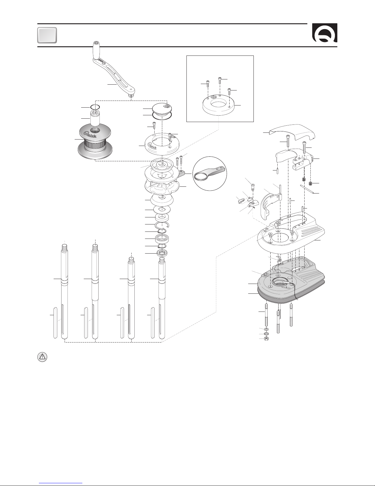
Smontare una volta all'anno il barbotin e la campana attenendosi alla seguente sequenza:
VERSIONE CON CAMPANA
Con la leva (1) svitare la bussola (7); estrarre la campana (6) ed il cono frizione superiore (8); svitare le viti di fissaggio (11) dello stacca catena (12) e rimuoverlo; estrarre il barbotin (9).
VERSIONE SENZA CAMPANA
Con la leva (1) svitare la bussola (2) e le viti (5); estrarre il coperchio barbotin (4) ed il cono frizione superiore (8); svitare le viti di fissaggio (11) dello stacca catena (12) e rimuoverlo; estrarre il barbotin (9).
Pulire ogni parte smontata affinché non si verifichino attacchi di corrosione e ingrassare (con grasso marino) il filetto dell'albero (19,
20, 21 o 22) e il barbotin (9) dove appoggiano i coni frizione (8 e 10).
Rimuovere eventuali depositi di ossido sui morsetti della cassetta teleruttori; cospargerli di grasso.
MANUTENZIONE
6
7
75
44
42
41
43
15
12
2
3
4
8
10
13
14
24
25
28
29
31
30
35
39
40
32
33
34
18
16
1921
5
5
5
5
5
9
27
27
25
26
36
11
45
232323
23
2022
27
17
16
37
38
1
76
77
A corredo nella scatola
solo nella versione
[ D ]
Page 11

11
IT
DN4 1500/1700/2000/3000W HYDRO - IT EN - REV008A
MANUTENZIONE
N°. DESCRIZIONE
1 LEVA SALPA PIEGATA
2 BUSSOLA FRIZIONE “DN” CROMATA
3 O-RING
4 COPERCHIO BARBOTIN
5 VITE
6 CAMPANA
7 BUSSOLA FRIZIONE “DN” CROMATA
8 CONO FRIZIONE SUPERIORE
9A BARBOTIN 1500W 10MM - 3/8"
9B BARBOTIN 1500W 12/13MM
10 CONO FRIZIONE INFERIORE
11 VITE
12 STACCACATENA
13 RONDELLA DI RINFORZO
14 PARAOLIO
15 ANELLO ELASTICO INTERNO
16 ANELLO ELASTICO ESTERNO
17 CUSCINETTO
18 PARAOLIO
19 ALBERO CORTO 1500W
20 ALBERO CORTO 1700/2000W
21 ALBERO LUNGO 1500W
22 ALBERO LUNGO 1700/2000W
23 CHIAVETTA
24 COVER GUIDA CATENA DN INOX
25 VITE
26 SUPPORTO GUIDA CATENA
27 SPINA
28 PERNO TENDICIMA
29 LEVA TENDICIMA
30 MOLLA BLOCCO BARBOTIN
31 LEVA BLOCCO BARBOTIN
32 COMANDO LEVA BLOCCO BARBOTIN
33 SICUREZZA COMANDO LEVA BLOCCO
34 PERNO BLOCCO BARBOTIN
35 VITE
36 COVER BASE DN INOX
37 MOLLA TENDICIMA
38 SENSORE REED
39 BASE SALPA DN
40 GUARNIZIONE DYLAN
41A PRIGIONIERO
41B PRIGIONIERO
42A RONDELLA 1500W
42B RONDELLA 1700/2000W
43A RONDELLA DENTELLATA 1500W
43B RONDELLA DENTELLATA 1700/2000W
44A DADO 1500W
44B DADO 1700/2000W
45 INSERTO PER RECUPERO MANUALE
46 RIDUTTORE 1500W - SERIE QUICK
47 RONDELLA
48 DADO AUTOBLOCCANTE
49 O-RING RIDUTTORE1500/1700W
50 RIDUTTORE - 1700W - SERIE QUICK
51 CHIAVETTA
52A MOTORE 1500W 12V
52B MOTORE 1700W 12V
52C MOTORE 1700W 24V
53 CARTER 1500/1700W
54 GUARNIZIONE MORSETTERIA 1000W
55 COPERCHIO MORSETTERIA 1000W
56 VITE
57 GUARNIZIONE FONDO 1000W
58 COPERCHIO FONDO 1000W
59 PASSACAVO
60 RIDUTTORE 2000W - SERIE QUICK
61 VITE
62 O-RING RIDUTTORE 2000W
63 CARTER MOTORE 2000/2300W
64 CHIAVETTA
65 MOTORE 2000W 24V
66 O-RING COPERCHIO FONDO
67 COPERCHIO FONDO
68 GUARNIZIONE MORSETTERIA INF.
69 GUARNIZIONE MORSETTERIA SUP.
70 COPERCHIO MORSETTERIA SUP.
71 VITE AUTOFILETTANTE
72 VITE AUTOFILETTANTE
73 GUARNIZ. FLANGIA RIDUT. TOP TG60
74 GUARNIZ. FLANGIA RIDUT. TOP TG70
75 O-RING BUSSOLA
76 MOLLA
77 SPINA COVER GUIDA CATENA
MOTORIDUTTORE 2000W
MOTORIDUTTORI 1500 - 1700W
53
54
55
56
57
58
59
52
51
50
49
73
47
48
49
46
47
48
74
70
71
72
66
67
68
69
63
65
64
62
74
61
47
60
Page 12

12
IT
DN4 1500/1700/2000/3000W HYDRO - IT EN - REV008A
SALPA ANCORA IDRAULICO
PROCEDURA DI MONTAGGIO
Posizionare la parte superiore, inserendo la guarnizione fra la coperta e la base e collegare a questa la parte inferiore, infilando l’albero
nel riduttore. Fissare il salpa ancora avvitando i dadi sui prigionieri di bloccaggio. Collegare i tubi provenienti dalla valvola distributrice
alle due flangette del motore idraulico (vedi schema di collegamento a pag.13).
Quick® si riserva il diritto di apportare modifiche alle caratteristiche tecniche dell'apparecchio e al contenuto di questo manuale senza alcun preavviso.
In caso di discordanze o eventuali errori tra il testo tradotto e quello originario in italiano, fare riferimento al testo italiano o inglese.
F
LA CONFEZIONE CONTIENE:
salpa ancora idraulico (top + motoriduttore) - dima di foratura - leva - viterie (per l'assemblaggio) -
manuale di istruzioni - condizioni di garanzia.
ATTREZZI NECESSARI PER L'INSTALLAZIONE:
trapano con punta: Ø 12 mm (15/32"); a tazza Ø 90 mm (3"1/2);
chiave esagonale: 17 mm.
ACCESSORI QUICK® CONSIGLIATI:
deviatore da pannello (mod. 800) - Pulsantiera stagna (mod. HRC 1002) - Pulsante a piede (mod.
900) - Interruttore magneto-idraulico - Conta catena per l'ancoraggio (mod. CHC 1102M e CHC 1202M) - Sistema di comando via radio
RRC (mod. R02, P02, H02).
(1) Misure effettuate con barbotin per catena da 12 mm.
(2) Su richiesta possono essere forniti alberi e prigionieri per spessori di coperta maggiori.
MODELLO IDRAULICO DN4 HYDRO - / D
Tipologia motore Reversibile ad ingranaggi
Cilindrata 9,6 cc 0,59 in
3
Capacità di sollevamento • 100 bar = 600 kg • 150 bar = 1000 kg • 1450 psi = 1322,8 lb • 2176 psi = 2204,6 lb
Velocità di recupero al carico di lavoro (1) 40 lt /min = 20 mt/min 9,1 USG/min = 76 ft/min
Spessore coperta (2) 40 ÷ 80 mm 1” 9/16 ÷ 3” 5/32 inch
Peso - modello senza campana 39,0 kg 86,0 lb
Peso - modello con campana 44,2 kg 97,4 lb
VALORI DI REGOLAZIONE (consigliati da Quick)
Portata 40 lt/min 9,1 USG/min
Pressione massima 150 bar 2176 psi
DADO (44)
GROWER (43)
RONDELLA (42)
ALBERO (20)
PRIGIONIERO (41)
GUARNIZIONE (40)
ESEMPIO INSTALLAZIONE
TOP SENZA CAMPANA
Dimensioni del modello a pagina 29
Page 13

13
IT
DN4 1500/1700/2000/3000W HYDRO - IT EN - REV008A
SALPA ANCORA IDRAULICO
62
78
81
82
47
83
82
79
80
60
47
61
SISTEMA BASE DN4 IDRAULICO
SCHEMA DI COLLEGAMENTO
INGRESSO
PRESSIONE
SERBATOIO
VALVOLA
DISTRIBUTRICE
MOTORE IDRAULICO
N°. DENOMINAZIONE
47 GROWER
60 RIDUTTORE - 2000W - SERIE QUICK
61 VITE
62 O-RING
78 FLANGIA
79 ADATTATORE TG70
80 CHIAVETTA
81 MOTORE AD INGRANAGGI 9,6 CC
BIDIREZIONALE
82 FLANGETTA 90° G3/4 FEMMINA
33 VITE
CONTACATENA DA PANNELLO
CHC 1202 M
COMANDO
DA PLANCIA
MOD.800
PULSANTIERA
CONTACATENA
MOD. CHC 1002 M
PULSANTIERA
MOD. H02
RICEVITORE
MOD. R02
ACCESSORI QUICK® PER L’AZIONAMENTO
DEL SALPA ANCORA IDRAULICO
TRASMETTITORI
RADIOCOMANDI RRC
TASCABILE
MOD. P02
PULSANTIERA
MULTIUSO
MOD. HRC 1002
PULSANTI A PIEDE
MOD. 900U E 900D
Page 14

14
IT
DN4 1500/1700/2000/3000W HYDRO - IT EN - REV008A
RICAMBI
11
12
1
9 10 7 8
3
2 5 6
4
13
Page 15

15
IT
DN4 1500/1700/2000/3000W HYDRO - IT EN - REV008A
RICAMBI
N°. DESCRIZIONE CODICE
1 OSP BUSSOLA CAMPANA SERIE DN CROMATA FVSSGMSDCPDN100
2 OSP CAMPANA SALPA 1500/2000W “DN” FVSSMSE15DN0A00
3 OSP KIT BLOCCO BARBOTIN DN/AL FVSSBLBBDN00A00
4A OSP BARBOTIN 1500W 12MM-13MM DYLAN FVSSB1512130A00
4B OSP BARBOTIN 1500W 10MM-3/8” DYLAN FVSSB1510380A00
5 OSP KIT TENDICIMA DYLAN FVSSTCDN0000A00
6 OSP INSERTO RECUPERO MANUALE 1500W FVSSRM150000A00
7 OSP CONI FRIZIONE DYLAN FVSSCFDN0000A00
8 OSP COPERCHIO BARBOTIN DYLAN FVSSCPBBDN00A00
9A OSP KIT ALBERO DN 1500 FVSSADN15000A00
9B OSP KIT ALBERO DN 2000 FVSSADN20000A00
10A OSP KIT ALBERO DN 1500 D FVSSADN1500DA00
10B OSP KIT ALBERO DN 2000 D FVSSADN20000DA00
11 OSP BASE SALPA 1500/2000W SERIE DN COMP FVSSBDN15000A00
12A OSP TOP DYLAN 1500W D 10MM-3/8" FVSSTDN15D10A00
12B OSP TOP DYLAN 1500W D 12MM-13MM FVSSTDN15D12A00
12C OSP TOP DYLAN 1700/2000W D 10MM-3/8" FVSSTDN20D10A00
12D OSP TOP DYLAN 1700/2000W D 12MM-13MM FVSSTDN20D12A00
13A OSP TOP DYLAN 1500W 10MM-3/8" FVSSTDN15010A00
13B OSP TOP DYLAN 1500W 12MM-13MM FVSSTDN15012A00
13C OSP TOP DYLAN 1700/2000W 10MM-3/8” FVSSTDN20010A00
13D OSP TOP DYLAN 1700/2000W 12MM-13MM FVSSTDN20012A00
14A OSP MOTORE SALPANCORA 1500W 12V FVSSM1512000A00
14B
OSP MOTORE SALPANCORA 1700W 12V FVSSM1712000A00
14C
OSP MOTORE SALPANCORA 1700W 24V FVSSM1724000A00
14D
OSP MOTORE SALPANCORA 2000W 24V FVSSM2024000A00
15A OSP RIDUTTORE 1500W SALPA SERIE QUICK FVSSMR15TG70A00
15B
OSP RIDUTTORE 1700W SALPA SERIE QUICK FVSSMR17TG70A00
15C
OSP RIDUTTORE 2000W SALPA SERIE QUICK FVSSMR20TG70A00
16A OSP MOTORIDUTTORE 1500W 12V QUICK FVSSR1512Q00A00
16B
OSP MOTORIDUTTORE 1700W 12V QUICK FVSSR1712QR0A00
16C
OSP MOTORIDUTTORE 1700W 24V QUICK FVSSR1724QR0A00
16D
OSP MOTORIDUTTORE 2000W 24V QUICK FVSSR2024Q00A00
14
15
16
Page 16

16
TECHNICAL DATA
EN
DN4 1500/1700/2000/3000W HYDRO - IT EN - REV008A
Quick® reserves the right to introduce changes to the equipment and the contents of this manual without prior notice.
In case of discordance or errors in translation between the translated version and the original text in the Italian language, reference will be made to the Italian or English text.
F
a
a b c d a b c d
a
a
a
a
a
a
a
1° EXAMPLE:
DN4 1512D
2° EXAMPLE:
DN4 2024
DN4 15 12 D DN4 20 24
-
Name of the line:
[ DN4 ] =
base in stainless steel AISI 316 and
anodized aluminium
in hard oxide
Motor output:
[ 15 ] = 1500 W
[ 17 ] = 1700 W
[ 20 ] = 2000 W
[ 30 ] = 3000 W
Motor supply voltage:
[ 12 ] = 12 V
[ 24 ] = 24 V
[ TR ] = 230 V / 400 V
Drum:
[ D ] = with drum
[ - ] = without drum
(1) After an initial period of use.
(2) Measurements taken with a gypsy for a 12/13 mm chain.
(3) Minimum allowable value for a total length L<20m. Determine the cable size according to the length of the wiring.
(4) With circuit breaker designed for direct currents (DC) and delayed-action (thermal-magnetic or hydraulic-magnetic).
(5) On request, shafts and studs can be supplied for greater deck thicknesses.
a b c d
(*) The values indicated in the table refer to a rope and chain combination manufactured with the Quick® system, do not guarantee the correct functioning with other types of anchor-rode.
GYPSY
10 mm - 3/8” 12/13 mm
Chain size
10 mm 10 mm 3/8” 3/8” 13 mm 12 mm 7/16”
DIN 766 ISO G4 BBB DIN 766 ISO G4
Rope size (*) 5/8” (15,8 mm) - 3/4” (19 mm) 3/4” (19 mm)
Models’ dimensions on page 28/29
MODELS DN4 - / D
MOTOR POWER 1500 W 1700 W 2000 W
Motor supply voltage 12 V 12 V 24 V 24 V
Maximum pull 1100 Kg (2425.1 lb) 1150 Kg (2535.3 lb) 1200 Kg (2645.5 lb) 1600 Kg (3527.4 lb)
Maximum working load 400 Kg (881.8 lb) 470 Kg (1036.2 lb) 570 Kg (1256.6 lb) 750 kg (1653.5 lb)
Working load 135 Kg (297.6 lb) 155 kg (341.7 lb) 190 Kg (418.9 lb) 250 Kg (551.1 lb)
Current absorption @ working load (1) 150 A 170 A 95 A 105 A
Maximum chain speed (2) 35,2 m/min (115.5 ft/min) 33,5 m/min (109.9 ft/min) 39,0 m/min (128.0 ft/min) 35,0 m/min (114.8 ft/min)
Max. chain speed @ working load (2) 19,0 m/min (62.3 ft/min) 16,2 m/min (53.1 ft/min) 20,8 m/min (68.2 ft/min) 22,3 m/min (73.2 ft/min)
Motor cable size (3) 50 mm
2
(AWG0) 50 mm2 (AWG0) 25 mm2 (AWG3) 35 mm2 (AWG2)
Protection circuit breaker (4) 100 A 100 A 60 A 80 A
Deck thickness (5)
25 ÷ 50 mm
(31/32” ÷ 1” 31/32)
30 ÷ 70 mm (1” 3/16” ÷ 2” 3/4)
Weight - model without drum 23,7 Kg (52.2 lb) 25,6 Kg (56.4 lb) 25,6 kg (56.4 lb) 31,2 Kg (68.8 lb)
Weight - model with drum 25,0 Kg (55.1 lb) 26,9 Kg (59.3 lb) 26,9 kg (59.3 lb) 32,5 Kg (71.6 lb)
MODEL DN4 AC - / D
MOTOR POWER 3000 W TR
Motor supply voltage 230/400 V
Maximum pull 2800 Kg (6172.9 lb)
Maximum working load 930 Kg (1984.2 lb)
Maximum chain speed (2) 15,0 m/min (49.2 ft/min)
Deck thickness (5) 30 ÷ 70 mm (1” 3/16” ÷ 2” 3/4)
Weight - model without drum 38,0 kg (83.8 lb)
Weight - model with drum 40,0 kg (88.2 lb)
HOW TO IDENTIFY THE WINDLASS THROUGH THE CODE:
Page 17

17
INSTALLATION
EN
DN4 1500/1700/2000/3000W HYDRO - IT EN - REV008A
WARNING:
before wiring up, be sure the electrical cables are not live.
FITTING PROCEDURE:
when the ideal position has been established, drill four holes using the drilling template provided.
Remove excess material from the chain passage, refine and flatten with a specialized product (marine paint, gel coat or two pack epoxy)
to assure free passage for both rope and chain. Position the upper section, inserting the gasket between the deck and the base and
connect the lower section to the assembly, inserting the shaft into the reduction unit.
Fix the windlass by screwing the nuts onto the fixing studs. Connect the supply cables from the windlass to the contactor unit.
PAINT
40 cm (16”)
Max
5 mm
(3/16”)
45°
90°
90°
90°
BEFORE USING THE WINDLASS READ THESE INSTRUCTIONS CAREFULLY.
IF IN DOUBT, CONTACT YOUR NEAREST “QUICK
®
” DEALER.
WARNING:
the Quick® windlasses are designed to weigh the anchor. Do not use the equipment for other purposes.
Quick® shall not be held responsible for damage to equipment and/or personal injury, caused by a faulty use of the equipment.
The windlass is not designed for the loads that might occur in extreme weather conditions (storms). Always deactivate the
windlass when not in use.
Check that there are no swimmers nearby before dropping anchor. The splice between the rope
and the chain must be tightly woven for the rope to slide easily into the gypsy shape. For any problem or request, feel free to contact
Quick
®
Technical Service. For improved safety we recommend installing at least two anchor windlass controls in case one is acci-
dentally damaged. We recommend the use of the Quick® hydraulic-magnetic switch as the motor safety switch.
Secure the chain with a further device before starting the navigation. The contactor unit or reversing contactor unit must be installed in a point protected from accidental water contact. After completing the anchorage, secure the chain or rope to fixed points
such as chain stopper or bollard.
To prevent accidental releases, the anchor must be secured. The windlass shall not be used as the
only securing device.
Isolate the windlass from the power system during navigation (switch the circuit breaker off) and lock the chain
securing it to a fixed point of the boat.
There must not be flammable materials in the peak or in the area where the windlass motor is.
THE PACKAGE CONTAINS:
windlass (on deck unit + motorgearbox) - contactor unit - base gasket - drill template - handle - bolts and
screws (for assembly) - user’s manual - conditions of warranty.
TOOLS REQUIRED FOR INSTALLATION:
drill and drill bits: Ø 5 mm (3/16”), Ø 9 mm (23/64”) and Ø 11 mm (7/16”)
Ø 80 mm (3" 9/64) hollow mill; hexagonal wrenche: 13 mm.
“QUICK®”ACCESSORIES RECOMMENDED:
anchoring RL control board (mod. 800) - Waterproof hand helds R/C (mod. HRC1002)
- Foot switch (mod. 900) - Hydraulic-magnetic circuit breaker - Anchor chain counter (mod. CHC1102M and CHC1202M) - Radio control
RRC (mod. R02, P02, H02).
INSTALLATION REQUIREMENTS:
the windlass must be positioned with the gypsy aligned with the bow roller. Ensure that the upper and lower surfaces of the deck are as parallel as possible. If this is not the case, compensate the difference appropriately (a lack of
parallelism could result in a loss of motor power). The deck thickness must be included among the figures listed in the table. In cases of
other thicknesses it is necessary to consult a Quick
®
retailer. There must be no obstacles under deck to the passage of cables, rope and
chain; lack of depth of the peak could cause jamming.
Page 18

18
EN
DN4 1500/1700/2000/3000W HYDRO - IT EN - REV008A
-
+
BASIC SYSTEM DN4 DC
MULTI-PURPOSE
WATERTIGHT HAND HELD
REMOTE CONTROL
MOD. HRC 1002
WINDLASS
MOTOR
BATTERY
HYDRAULIC-
MAGNETIC
CIRCUIT BREAKER
(SEE TABLE ON
PAGE 16)
CONTACTOR UNIT
MOD. T6315-12 (12V)
MOD. T6315-24 (24V)
C
A2
FOOT SWITCHES MOD. 900U AND 900D
BLACK
BROWN
BLUE
BROWN
BLACK
BLUE
A1
FUSE
4A (12V)
2A (24V)
L = L1 + L2 + L3 + L4
L4
L2
L3
L1
L3
CONNECTION DIAGRAM
RADIO POCKET
QUICK® ACCESSORIES
FOR WINDLASS OPERATION
TRANSMITTERS
RRC REMOTE RADIO CONTROLS
WATERTIGHT
PANEL
CHAIN COUNTER
CHC 1202 M
WINDLASSES
CONTROL
BOARD
MOD.800
WATERTIGHT HAND HELD
CHAIN COUNTER
MOD. CHC 1002 M
HANDHELD
MOD. H02
RECEIVER
MOD. R02
POCKET
MOD. P02
Page 19

19
EN
DN4 1500/1700/2000/3000W HYDRO - IT EN - REV008A
24V
KM1
W2
U1
R
S
T
L1 XP
PE XP
R
V1 W1
U1
V1
W1
XP XP XP
U2 V2
U1 V1 W1
24V
KM2
FU1 13-25A aM
FU1 13-25A aM
L2 XP
S
FU1 13-25A aM
L3 XP
T
R S T
M
1
~
BASIC SYSTEM DN4 3000W 230V AC
WINDLASS
MOTOR
230V CA Max
3KW
TERMINAL BOARD
THREE-PHASE CONNECTION DIAGRAM
SENSOR
WATERTIGHT
HAND HELD
CHAIN-COUNTER
MOD. CHC1102 M
WATERTIGHT PANEL
CHAIN-COUNTER
MOD. CHC1202 M
-
+
DOWN
UP
BLUE
BROWN
BLACK
BLUE
BROWN
BLACK
DOWN
SENSOR
UP
-
+
CAN H
CAN L
GREY
RED
GREEN
BROWN
WHITE
BLUE
BLACK
BLUE
BROWN
BLACK
150
CAN H
CAN L
CAN H
CAN L
BATTERY 24V
MULTI-PURPOSE
WATERTIGH HAND HELD
REMOTE CONTROL
MOD. HRC1002
RADIO RECEIVER RRC
MOD. R02 (2CH)
WINDLASS
CONTROL BOARD
MOD. 800
MOD. 900/D
DOWN
FOOT SWITCH
MOD. 900/U
UP
Page 20

20
EN
DN4 1500/1700/2000/3000W HYDRO - IT EN - REV008A
THREE-PHASE CONNECTION DIAGRAM
M
1
~
24V
KM1
W2
U1
R
S
T
L1 XP
PE XP
R
V1 W1
U1
V1
W1
XP XP XP
U2 V2
U1 V1 W1
24V
KM2
FU1 8 -16A aM
FU1 8 -16A aM
L2 XP
S
FU1 8 -16A aM
L3 XP
T
R S T
BASIC SYSTEM DN4 3000W 400V AC
WINDLASS
MOTOR
400V CA Max
3KW
TERMINAL BOARD
SENSOR
WATERTIGHT
HAND HELD
CHAIN-COUNTER
MOD. CHC1102 M
WATERTIGHT PANEL
CHAIN-COUNTER
MOD. CHC1202 M
-
+
DOWN
UP
BLUE
BROWN
BLACK
BLUE
BROWN
BLACK
DOWN
SENSOR
UP
-
+
CAN H
CAN L
GREY
RED
GREEN
BROWN
WHITE
BLUE
BLACK
BLUE
BROWN
BLACK
150
CAN H
CAN L
CAN H
CAN L
BATTERY 24V
MULTI-PURPOSE
WATERTIGH HAND HELD
REMOTE CONTROL
MOD. HRC1002
RADIO RECEIVER RRC
MOD. R02 (2CH)
WINDLASS
CONTROL BOARD
MOD. 800
MOD. 900/D
DOWN
FOOT SWITCH
MOD. 900/U
UP
Page 21

21
EN
DN4 1500/1700/2000/3000W HYDRO - IT EN - REV008A
WARNING:
before weighing anchor release the gypsy. Check
that the control (32/33) that locks the gypsy is disengaged.
1)
Release the gypsy safety lock (33).
2)
Have the gypsy lock control (32) slide toward the stern.
3)
Automatic inserting of the gypsy lock (31).
WARNING:
stay clear of the chains, ropes and gypsy. Make sure the electric motor is off when windlass is used manually (even
when using the handle to disengage the clutch). In fact people with windlass remote controls (hand-held remote control or ra
-
dio-controlled systems) might accidentally operate it.
WARNING:
secure the chain with a device before starting the navigation.
WARNING:
do not operate the windlass by using the electrical power when the handle is inserted in the drum or into the gypsy
cover.
WARNING:
Quick® suggests the use of a protection such as a fuse/thermal-magnetic/ hydraulic-magnetic circuit breaker of suit-
able power according to the motor chosen, in order to protect it from any overheating or short circuits. The circuit breaker can be
used to cut off power to the windlass control circuit and so avoid accidental activation.
CLUTCH USE
The clutch (8 and 10) provides a link between the gypsy and the main shaft (19, 20, 21 or 22). The clutch can be released (disengagement) by using the handle (1) which, when inserted in the bush (7) of the drum or of the gypsy cover (2), must be turned counter-clockwise. The clutch will be re-engaged by turning it clockwise (engagement).
WEIGHING THE ANCHOR
- Turn on the engine. Make sure the clutch is engaged and remove the handle. Press the UP button on the
control provided. If the windlass stops and the hydraulic magnetic switch (or thermal cutout) has not tripped, wait a few seconds and
try again (avoid keeping the button pressed). If the hydraulic magnetic switch, has tripped, reset it and wait a few minutes before weigh
ing anchor once again. If, after a number of attempts, the windlass is still blocked, we suggest to move the boat to release the anchor.
Check the upward movement of the chain for the last few meters in order to avoid damages to the bow.
CASTING THE ANCHOR
- The anchor can be cast by using the electrical control or manually. To operate manually, the clutch must
be disengaged allowing the gypsy to revolve and letting the rope or chain fall into the water. To slow down the chain, the handle must
be turned clockwise. To cast the anchor by using the electrical power, press the DOWN button on the control provided. In this manner,
anchor casting is under control and the chain and rope unwind evenly. In order to avoid any stress on the windlass -once the boat is
anchored- fasten the chain or secure it in place with a rope.
MANUAL ANCHOR WEIGHING (no drum version)
Disconnect the windlass power supply. Use the lock lever control (32/33) to
engage the lock lever (31) on the gypsy (9). Disengage the clutch (at least 2 turns of the bush anticlockwise), insert the lever (1) into the
seat in the gypsy cover (4) and manually take up the chain by rotating the lever clockwise. After the manual weighing procedure remove
the lever from its seat and insert it into the bush (2) to tighten the clutch.
Remove the lever (1) from the gypsy cover (4). Release the gypsy (9) using the control lever (32/33). Reconnect the windlass power
supply.
MANUAL ANCHOR WEIGHING (drum version)
Disconnect the windlass power supply. Use the lock lever control (32/33) to engage
the lock lever (31) on the gypsy (9). Use the lever (1) to completely loosen the bush (7) and pull off the drum (6). Insert the lever (1) into
the seat in the anchor weighing (45) and manually take up the chain by rotating the lever clockwise.
After the manual weighing procedure, remove the lever from its seat, reinsert the drum (6) and tighten the bush (7) to tighten the clutch.
Remove the lever (1) from the bush (7). Release the gypsy (9) using the control lever (32/33). Reconnect the windlass power supply.
DRUM USE
WARNING:
Before carrying out warping operations, check that the anchor and relative rope or chain are solidly fixed to a bitt or
another strong point on the boat.
For the independent use of the drum (6), turn the lock lever control (32/33) to engage the lock lever (31) of the gypsy (9), release the
clutch with the handle (1), (at least 2 turns of the bush anticlockwise). Remove the handle from the bush (7) on the gypsy, wrap the rope
around the drum (2 turns). Activate the windlass control, keeping the rope under tension during take up. By varying the tension during
take up it is possible to modify the rope winding speed.
WARNING: during take up maintain a safe distance between hands and windlass drum.
Once take up is complete, screw up the clutch by tightening the gypsy drum clockwise and secure the rope to a bitt or other strong
point on the boat.
WARNING - USAGE
LOCK DISENGAGED
LOCK ENGAGED
1
2
3
33
32
31
Page 22

22
EN
DN4 1500/1700/2000/3000W HYDRO - IT EN - REV008A
MAINTENANCE
WARNING:
make sure the electrical power to the motor is switched off when working manually on the windlass. Carefully re-
move the chain or rope from the gypsy or the rope from the drum.
Quick
®
windlasses are manufactured with materials resistant to marine environments. In any case, any salt deposits on the outside
must be removed periodically to avoid corrosion and damage to the equipment.
The parts where salt may have built up should be washed thoroughly with fresh water.
Once a year, the drum and the gypsy are to be taken apart as follows:
DRUM VERSION
Use the handle (1) to loosen the bush (7); pull off the drum (6) and the top clutch cone (8); loosen the fixing screws (11) of the rope/chain
stripper (12) and remove it. Pull off the gypsy (9).
NO-DRUM VERSION
Use the handle (1) to loosen the bush (2) and the screws (5); to remove the gypsy cover (4); and the top clutch cone (8); loosen the fixing
screws (11) of the rope/chain stripper (12) and remove it. Pull off the gypsy (9).
Clean all the parts removed to avoid corrosion, and grease the shaft thread (18, 19, 20 or 21) and the gypsy (9) where the clutch cones
rest (7 and 9) (use grease suitable for marine environment).
Remove any oxide deposits from the terminals of the electric motor and the contactor unit; grease them.
6
7
75
44
42
41
43
15
12
2
3
4
8
10
13
14
24
25
28
29
31
30
35
39
40
32
33
34
18
16
1921
5
5
5
5
5
9
27
27
25
26
36
11
45
232323
23
2022
27
17
16
37
38
1
76
77
Provided in the box only
in the version
[ D ]
Page 23

23
EN
DN4 1500/1700/2000/3000W HYDRO - IT EN - REV008A
23
MAINTENANCE
N. DESCRIPTION
1 BENT ANCHOR WINCH LEVER
2 CHROME-PLATED “DN” CLUTCH BUSH
3 O-RING
4 GYPSY COVER
5 SCREW
6 DRUM
7 CHROME-PLATED “DN” CLUTCH BUSH
8 UPPER CLUTCH CONE
9A GYPSY 1500W 10MM - 3/8"
9B GYPSY 1500W 12/13MM
10 BOTTOM CLUTCH CONE
11 SCREW
12
CHROME-PLATED ROPE/CHAIN
STRIPPER
13 SPRING WASHER
14 OIL SEAL
15 INTERNAL CIRCLIP
16 EXTERNAL CIRCLIP
17 BEARING
18 OIL SEAL
19 SHORT SHAFT 1500W
20 SHORT SHAFT 1700/2000W
21 LONG SHAFT 1500W
22 LONG SHAFT 1700/2000W
23 KEY
24 “DN” CHAIN FALL COVER
25 SCREW
26 “DN” CHAIN GUIDE SUPPORT
27 PIN
28 MOORING ROPE PULLER PIN
29 PRESSURE LEVER
30 GYPSY LOCK SPRING
31 GYPSY LOCK LEVER
32 GYPSY LOCK LEVER CONTROL
33 LEVER LOCK CONTROL SAFETY
34 GYPSY LOCK PIN
35 SCREW
36 “DN” STAINLESS STEEL BASE COVER
37 SPRING FOR PRESSURE LEVER
38 SENSOR
39 WINDLASS DN BASE
40 GASKET / JIG DYLAN
41A STUD
41B STUD
42A WASHER 1500W
42B WASHER 1700/2000W
43A SPRING WASHER 1500W
43B SPRING WASHER 1700/2000W
44A NUT 1500W
44B NUT 1700/2000W
45
INSERT FOR MANUAL ANCHOR
WEIGHING
46 GEARBOX 1500W - QUICK SERIES
47 WASHER
48 SELF-LOCKING NUTS
49 O-RING - GEARBOX 1500/1700W
50 GEARBOX 1700W - QUICK SERIES
51 KEY
52A ELECTRIC MOTOR 1500W 12V
52B ELECTRIC MOTOR 1700W 12V
52C ELECTRIC MOTOR 1700W 24V
53
MOTOR CASING WATERTIGHT
1500/1700W
54 TERMINAL BOARD GASKET 1000W
55 TERMINAL BOARD COVER 1000W
56 SCREW
57 BOTTOM GASKET 1000W
58 BOTTOM PROTEC COVER 1000W
59 CABLE OUTLET
60 GEARBOX 2000W - QUICK SERIES
61 SCREW
62 O-RING - GEARBOX 2000W
63
WATERTIGHT MOTOR CASING
2000/2300W
64 KEY
65 ELECTRIC MOTOR 2000W 24V
66 BOTTOM COVER O-RING
67 BOTTOM COVER
68 LOWER TERMINAL BOARD GASKET
69 UPPER TERMINAL BOARD GASKET
70 UPPER TERMINAL BOARD COVER
71 SELF-TAPPING SCREW
72 SELF-TAPPING SCREW
73 GEARBOX FLANGE GASKET TOP TG60
74 GEARBOX FLANGE GASKET TOP TG70
75 O-RING - BUSH
76 SPRING
77 CHAIN GUIDE COVER PIN
MOTORGEARBOX 2000W
MOTORGEARBOXES 1500 - 1700W
53
54
55
56
57
58
59
52
51
50
49
73
47
48
49
46
47
48
74
70
71
72
66
67
68
69
63
65
64
62
74
61
47
60
Page 24

24
EN
DN4 1500/1700/2000/3000W HYDRO - IT EN - REV008A
HYDRAULIC WINDLASS
Quick® reserves the right to introduce changes to the equipment and the contents of this manual without prior notice.
In case of discordance or errors in translation between the translated version and the original text in the Italian language, reference will be made to the Italian or English text.
F
FITTING PROCEDURE
Position the upper section, inserting the gasket between the deck and the base and connect the lower section to the assembly, inserting
the shaft into the reduction unit. Fix the windlass by screwing the nuts onto the fixing studs.
Connect the hoses deriving from the selector valve to the flanges of the hydraulic motor (see connection diagram on page 25).
THE PACKAGE CONTAINS:
hydraulic windlass (on deck unit + motorgearbox) - drill template - handle - bolts and screws (for
assembly) - user’s manual - conditions of warranty.
TOOLS REQUIRED FOR INSTALLATION:
drill and drill bits: Ø 12 mm (15/32”); Ø 90 mm (3”1/2) hollow mill;
hexagonal wrenche: 17 mm.
“QUICK®”ACCESSORIES RECOMMENDED:
anchoring RL control board (mod. 800) - Waterproof hand helds R/C (mod. HRC1002) Foot switch (mod. 900) - Hydraulic-magnetic circuit breaker - Anchor chain counter (mod. CHC1102M and CHC1202M) - Radio control
RRC (mod. R02, P02, H02).
(1) Measurements taken with a gypsy for a 12 mm chain.
(2) On request, shafts and studs can be supplied for greater deck thicknesses.
HYDRAULIC MODEL DN4 HYDRO - / D
Motor type
Reversible gear-type
Motor power
9,6 cc 0,59 in
3
Lifting capacity
• 100 bar = 600 kg • 150 bar = 1000 kg • 1450 psi = 1322,8 lb • 2176 psi = 2204,6 lb
Max. chain speed @ working load (1)
40 lt /min = 20 mt/min 9,1 USG/min = 76 ft/min
Deck thickness (2)
40 ÷ 80 mm 1” 9/16 ÷ 3” 5/32 inch
Weight - model without drum 39,0 kg 86,0 lb
Weight - model with drum 44,2 kg 97,4 lb
SETTING VALUES (Suggested by Quick)
Flow rate
40 lt/min 9,1 USG/min
Maximum pression
150 bar 2176 psi
NUT (44)
GROWER (43)
WASHER (42)
SHAFT (20)
STUD (41)
GASKET (40)
EXAMPLE INSTALLATION
TOP WITHOUT DRUM
Model dimensions on page 29
Page 25

25
EN
DN4 1500/1700/2000/3000W HYDRO - IT EN - REV008A
HYDRAULIC WINDLASS
62
78
81
82
47
83
82
79
80
60
47
61
HYDRAULIC MOTOR
N. DESCRIPTION
47 GROWER
60 GEARBOX - 2000W - QUICK SERIES
61 VITE
62 O-RING
78 FLANGE
79 ADAPTER TG70
80 KEY
81 BIDIRECTIONAL GEAR-TYPE MOTOR
9,6CC
82 FLANGE 90° G3/4 FEMALE
33 SCREW
BASIC SYSTEM HYDRAULIC DYLAN
CONNECTION DIAGRAM
PRESSURE
INPUT
TANK
SELECTOR
VALVE
WATERTIGHT PANEL
CHAIN COUNTER CHC 1202 M
WINDLASSES
CONTROL
BOARD
MOD.800
WATERTIGHT
HAND HELD
CHAIN COUNTER
MOD. CHC 1002 M
HANDHELD
MOD. H02
RECEIVER
MOD. R02
QUICK® ACCESSORIES
FOR HYDRAULIC WINDLASS OPERATION
TRANSMITTERS
RRC REMOTE RADIO CONTROLS
RADIO POCKET
MOD. P02
MULTI-PURPOSE
WATERTIGH
HAND HELD
REMOTE CONTROL
MOD. HRC 1002
FOOT SWITCH
MOD. 900U AND 900D
Page 26

26
EN
DN4 1500/1700/2000/3000W HYDRO - IT EN - REV008A
SPARE PARTS
11
12
1
9 10 7 8
3
2 5 6
4
13
Page 27

27
EN
DN4 1500/1700/2000/3000W HYDRO - IT EN - REV008A
SPARE PARTS
N. DESCRIPTION CODE
1 OSP WINDLASS BUSH DN SERIES - CHROMED FVSSGMSDCPDN100
2 OSP WINDLASS DRUM 1500/2000W “DN” FVSSMSE15DN0A00
3 OSP KIT GYPSY LOCK DN/AL FVSSBLBBDN00A00
4A OSP GYPSY 1500W 12MM-13MM DYLAN FVSSB1512130A00
4B OSP GYPSY 1500W 10MM-3/8” DYLAN FVSSB1510380A00
5 OSP KIT PRESSURE LEVER DYLAN FVSSTCDN0000A00
6
OSP INSERT FOR MANUAL ANCHOR WEIGHING
1500W
FVSSRM150000A00
7 OSP CLUTCH CONES DYLAN FVSSCFDN0000A00
8 OSP GYPSY COVER DYLAN FVSSCPBBDN00A00
9A OSP KIT SHAFT DN 1500 FVSSADN15000A00
9B OSP KIT SHAFT DN 2000 FVSSADN20000A00
10A OSP KIT SHAFT DN 1500 D FVSSADN1500DA00
10B OSP KIT SHAFT DN 2000 D FVSSADN20000DA00
11
OSP WINDLASS BASE 1500/2000W SERIES DN
COMP
FVSSBDN15000A00
12A OSP TOP DYLAN 1500W D 10MM-3/8" FVSSTDN15D10A00
12B OSP TOP DYLAN 1500W D 12MM-13MM FVSSTDN15D12A00
12C OSP TOP DYLAN 1700/2000W D 10MM-3/8" FVSSTDN20D10A00
12D OSP TOP DYLAN 1700/2000W D 12MM-13MM FVSSTDN20D12A00
13A OSP TOP DYLAN 1500W 10MM-3/8" FVSSTDN15010A00
13B OSP TOP DYLAN 1500W 12MM-13MM FVSSTDN15012A00
13C OSP TOP DYLAN 1700/2000W 10MM-3/8” FVSSTDN20010A00
13D OSP TOP DYLAN 1700/2000W 12MM-13MM FVSSTDN20012A00
14A OSP WINDLASS MOTOR 1500W 12V FVSSM1512000A00
14B
OSP WINDLASS MOTOR 1700W 12V FVSSM1712000A00
14C
OSP WINDLASS MOTOR 1700W 24V FVSSM1724000A00
14D
OSP WINDLASS MOTOR 2000W 24V FVSSM2024000A00
15A OSP GEARBOX 1500W WINDLASS QUICK SERIES FVSSMR15TG70A00
15B
OSP GEARBOX 1700W WINDLASS QUICK SERIES FVSSMR17TG70A00
15C
OSP GEARBOX 2000W WINDLASS QUICK SERIES FVSSMR20TG70A00
16A OSP MOTORGEARBOX 1500W 12V QUICK FVSSR1512Q00A00
16B
OSP MOTORGEARBOX 1700W 12V QUICK FVSSR1712QR0A00
16C
OSP MOTORGEARBOX 1700W 24V QUICK FVSSR1724QR0A00
16D
OSP MOTORGEARBOX 2000W 24V QUICK FVSSR2024Q00A00
14
15
16
Page 28

DN4 1500/1700/2000/3000W HYDRO - IT EN - REV008A
162 (6
1
/
4
)
375 (14 49/64)
87
(3
1
/
2
)
277 (10 59/64)
105 (4
1
/
4
)
118 (4
5
/
8
)
189.5 (7
29
/
64
)
167 (6
37
/
64
)
172.5 (6
51
/
64
)
162 (6
1
/
4
)
375 (14 49/64)
87
(3
1
/
2
)
277 (10 59/64)
105 (4
1
/
4
)
118 (4
5
/
8
)
189.5 (7
29
/
64
)
407 (16)
170 (6
3
/
4
)
180 (7)
87
(3
1
/
2
)
105 (4
1
/
4
)
277 (10 59/64)
118 (4
5
/
8
)
189.5 (7
29
/
64
)
DIMENSIONI mm (inch)
DIMENSIONS
DN4 - / D
DC 1500 W
DN4 - / D
DC 1700 W
DN4 - / D
DC 2000 W
Page 29

29
DN4 1500/1700/2000/3000W HYDRO - IT EN - REV008A
244 (9
39
/
64
)
87
(3
1
/
2
)
105 (4
1
/
4
)
277 (10 59/64)
118 (4
5
/
8
)
189.5 (7
29
/
64
)
480 (18 57/
64
)
158 (6
7
/
32
)
309,5 (12 3/16)
170 (6
3
/
4
)
180 (7)
87
(3
1
/
2
)
105 (4
1
/
4
)
277 (10 59/64)
118 (4
5
/
8
)
189.5 (7
29
/
64
)
DIMENSIONI mm (inch)
DIMENSIONS
DN4 - / D
AC 3000 W
230/400 V
DN4 - / D
HYDRO
Page 30

NOTES
Page 31

Page 32

QUICK® S.p.A. - Via Piangipane, 120/A - 48124 Piangipane (RAVENNA) - ITALY
Tel. +39.0544.415061 - Fax +39.0544.415047
www.quickitaly.com - E-mail: quick@quickitaly.com
Codice e numero seriale del prodotto
Product code and serial number
EN
IT
DN4 DYLAN SERIES
1500/1700/2000W DC
3000W AC - HYDRO
R008
a
 Loading...