

Page 1
REV 005B
High
Quality
Nautical
Equipment
CHAIN COUNTER
CHC 1102 M
UP ALARM
SPEED
000 M/M
GB
User's Manual CHAIN COUNTER CHC 1102 M
FR
Manuel de l'utilisateur COMPTEUR DE CHAÎNE CHC 1102 M
Page 2

Page 3

GB
FR
INDEX
SOMMAIRE
Pag. 4
CHARACTERISTICS AND INSTALLATION
Pag. 5
INSTALLATION
INSTALLATION
Pag. 6
INSTALLATION
Pag. 7
INSTALLATION
Pag. 8
INSTALLATION
Pag. 9
INSTALLATION
Pag. 10
INSTALLATION
Pag. 11
INSTALLATION
Pag. 12
CHAIN COUNTER OPERATION
Pag. 13
CHAIN COUNTER OPERATION
Pag. 14
CHAIN COUNTER OPERATION
Pag. 15
CHAIN COUNTER OPERATION
Pag. 16
SETTING THE CHAIN COUNTER
Pag. 17
SETTING THE CHAIN COUNTER
Pag. 18
SETTING THE CHAIN COUNTER
Pag. 20
SETTING THE CHAIN COUNTER
Pag. 22
SETTING THE CHAIN COUNTER
Pag. 23
SETTING THE CHAIN COUNTER
Pag. 24
SETTING THE CHAIN COUNTER
Pag. 25
SETTING THE CHAIN COUNTER
Pag. 26
SETTING THE CHAIN COUNTER
Pag. 27
SETTING THE CHAIN COUNTER
Pag. 29
SYSTEM ERRORS AND FAULTS
Pag. 30
MAINTENANCE - TECHNICAL DATA
Pag. 33
Pag. 34
CARACTÉRISTIQUES ET INSTALLATION
Pag. 35
INSTALLATION
INSTALLATION
Pag. 36
INSTALLATION
Pag. 37
INSTALLATION
Pag. 38
INSTALLATION
Pag. 39
INSTALLATION
Pag. 40
INSTALLATION
Pag. 41
INSTALLATION
Pag. 42
FONCTIONNEMENT DE L'APPAREIL
Pag. 43
FONCTIONNEMENT DE L'APPAREIL
Pag. 44
FONCTIONNEMENT DE L'APPAREIL
Pag. 45
FONCTIONNEMENT DE L'APPAREIL
Pag. 46
RÉGLAGE DE L'APPAREIL
Pag. 47
RÉGLAGE DE L'APPAREIL
Pag. 48
RÉGLAGE DE L'APPAREIL
Pag. 50
RÉGLAGE DE L'APPAREIL
Pag. 52
RÉGLAGE DE L'APPAREIL
Pag. 53
RÉGLAGE DE L'APPAREIL
Pag. 54
RÉGLAGE DE L'APPAREIL
Pag. 55
RÉGLAGE DE L'APPAREIL
Pag. 56
RÉGLAGE DE L'APPAREIL
Pag. 57
RÉGLAGE DE L'APPAREIL
Pag. 59
ERREURS ET PROBLÈMES SYSTÈME
Pag. 60
ENTRETIEN - CARACTÉRISTIQUES TECHNIQUES
Pag. 63
- Installing the laps sensor
- Installing the magnet - Installing the sensor
- Installing the socket
- Installing the support - inserting the chain counter into the support
- Extracting the chain counter from the support - Electric connections
- The wiring diagram
- Installing the terminals
- Chain counter calibration - Multiple chain counters
- Installation du capteur de proximité
- Montage de l'aimant - Montage du capteur
- Intallation de la prise
- Installation du support - Insertion du compteur de chaîne dans le support
- Extraction du compteur de chaîne du support - Branchement électrique
- Schéma électrique
- Installation de la résistance de terminaison
- Etalonnage de l'appareil - Appareils multiples
- Structure du menu
- Remise a zêro / Fonction
- Donnees personnalisee
- Date et Heure
- Langue / Calibrage
- Calibrage / Tour barbotin
- Chute libre auto
- Calibrage automatique
- Controles
- Configuration CAN
- Main window
- Windlass electric drive
- Turning the torch ON and OFF - Monitoring
- Winch mode
- The structure of the menus
- Counter reset / Functions
- Personal set
- Date and time
- Language / Calibration
- Calibration / Gypsy lap
- Auto free fall
- Automatic calibration
- Utility
- CAN configuration
- Fenêtre principale
- Fonction commande à distance du guindeau
- Surveillance
- Mode poupée seule
CHC1102M GB F - REV005B
3
Page 4

GB
CHARACTERISTICS AND INSTALLATION
CHAIN COUNTER CHC 1102 M
Our vast experience in the world of sailing has allowed us to design and develop the chain counter CHC
1102 M whose performance is widely superior to those of similar instruments available on today's market.
The chain counter CHC 1102 M allows the windlass to be activated to get the anchor aweigh or lower the
anchor providing the measure of the chain lowered.
Other important advantages which the chain counter offers, are:
• Simple user-friendly interface.
• Information displayed in 5 different languages.
• Automatic lowering function.
• Up alarm function.
• Locked keys function.
• Windlass management with auto free fall.
• Can also be used in winch operations.
• Chain speed displayed.
• Supply voltage displayed.
• Equipped with clock/calendar.
• Depth of chain lowered shown in meters or feet.
• Graphic LCD display screen that can be easily read at various angles.
• Backlight display screen with 8 brightness levels.
• 8 different display contrast levels can be set.
• Automatic display contrast compensation according to environmental temperature.
• Universal power supply (12/24Vdc).
• Backlight illuminated function keys.
• Equipped with led torch.
• CAN BUS interface for data transfer.
• Capable of operating in a wide range of ambient temperatures.
• Water-proof housing
INSTALLATION
BEFORE ATTEMPTING TO USE THE CHAIN COUNTER CAREFULLY READ THIS USER'S MANUAL.
IF IN DOUBT, CONTACT YOUR NEAREST DEALER OR QUICK
In case of discordance or errors in translation between the translated version and the original text in
F
the Italian language, reference will be made to the Italian or English text.
This device was designed and constructed for use on recreational crafts.
F
Other forms of use are not permitted without written authorization from the company Quick
The Quick
in this User's manual. Quick
damage caused by inappropriate use of the chain counter, incorrect installation or possible errors present
in this manual.
®
chain counter has been designed and constructed solely for the tasks and purposes given
®
company shall not be held responsible for any direct or indirect property
®
CUSTOMER SERVICE.
®
.
THE OPENING OF THE CHAIN COUNTER BY UNAUTHORIZED PERSONNEL MAKES THE
WARRANTY VOID.
THE PACKAGE CONTAINS: chain counter - support - socket - laps sensor kit - 150 ohm terminator -
gasket - screws for securing the socket - drilling templates - conditions of warranty - this user's manual.
4
CHC1102M GB F - REV005B
Page 5
INSTALLATION
GB
CHAIN COUNTER INSTALLATION TAKES PLACE IN THREE STEPS:
installation of the laps sensor on the windlass, installation of the socket and electrical connections.
®
Quick
windlasses
All Quick® windlasses come with a laps sensor suitable for use with chain counter CHC 1102 M.
Other windlasses
In order for the chain counter to measure the length of the chain lowered, it has to count the number of
revolutions completed by the gear that drives the chain (gypsy).
A laps sensor kit is supplied with the chain counter. This kit includes a cylindrical magnet, a magnetic field
sensor and two plastic adaptors to be used to fix the sensor. The magnet is to be fixed to the gypsy while
the magnetic sensor is to be fixed to the windlass base.
The standard installation procedure is described below. Unfortunately we cannot describe a procedure applicable to all types of windlass. Adapt this procedure to satisfy your own individual requirements.
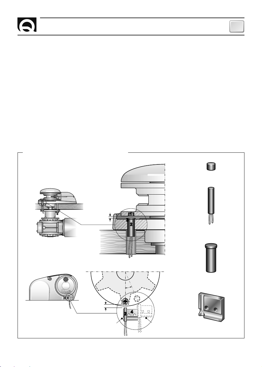
EXAMPLES OF LAPS SENSOR INSTALLATION
vertical windlasses
1
MAGNET
horizontal windlasses
CHC1102M GB F - REV005B
Max. 10 mm
Max. 10 mm
Ideal
installation
11
22
2
2
3
3
± 20°
11
22
22
44
Maximum
removal
2
3
4
SENSOR
ADAPTOR
ADAPTOR
5
Page 6

GB
INSTALLATION
INSTALLING THE MAGNET
Take the gypsy off the windlass (consult the windlass user's manual). Find the spot most suitable for the
magnet housing based on the following criteria:
• The magnet should not be installed in an area that the chain passes through (outer areas).
• The location should be preferably made in the area where the gypsy is thickest (in order not to weaken
the structure).
• Regarding horizontal windlasses, make sure it is located near the edge of the gypsy.
• Regarding vertical windlasses, make certain the sensor is installed on the base at the circumference
"traced" by the magnet.
• The magnet can protrude from the gypsy; make certain it does not interfere with the base or sensor.
• The magnet should be as close to the sensor as possible.
Once the hole has been drilled, glue the magnet inside it. Make sure the glue covers the part of the
magnet still visible. Use glue designed for metals, resistant to brackish ambients and capable of
withstanding temperatures ranging from -30 to +80 °C. Generally speaking, some epoxy-based bicomponent glues satisfy these requirements.
Several magnets can be installed on the same gypsy to increase the precision with which the chain
counter reads (not provided). Place any additional magnets around the same circumference equally
spaced apart.
INSTALLING THE SENSOR
Locate the most suitable position to secure the sensor to the base according to the following criteria:
• The sensor should not be installed in an area that the chain passes through.
• If holes are made in the base, make sure they do not interfere with normal operation, do not
weaken the structure or cause lubricant to flow out (windlasses with oil-bathed gears).
• Regarding vertical windlasses, make certain the sensor can be installed on the base at the
circumference "traced" by the magnet.
• The magnet should be as close to the sensor as possible.
Use the plastic adaptors provided to secure the sensor. Use a sheath to protect the sensor cables.
Once installed, make sure the laps sensor works properly. Place the gypsy so that the magnet is aligned
with the sensor and check electrical continuity between the two sensor cables. When the magnet is
moved away from the sensor electrical continuity should no longer be present.
6
CHC1102M GB F - REV005B
Page 7
INSTALLATION
GB
INSTALLING THE SOCKET
The standard installation procedure is described below.
Unfortunately we cannot describe a procedure applicable to all types of windlasses. Adapt this procedure
to satisfy your own individual requirements.
Find the spot most suitable for the socket based on the following criteria:
• The socket is to be installed in an area where it can be easily reached by the user.
• Select a clean, smooth, flat spot.
• A rear point that provides access to the socket's fixing surface must be present for installation and
maintenance purposes.
• Leave enough space free behind the installation spot to conveniently run the socket's cable.
• The back of the socket must be protected against contact with water and moisture.
• Pay careful attention when drilling the panel or parts of the boat. This hole should not weaken or break/
crack the boat's structure.
The chain counter meets standard EMC (electromagnetic compatibility). In any case correct installation is
fundamental in order not to affect its performance or interfere with operation of instruments found near it.
For this reason the chain counter must be at least:
• 25 cm away from the compass.
• 50 cm away from any radio receivers.
• 1 m away from any radio transmitters (except for SSB).
• 2 m away from any radio transmitters SSB.
• 2 m away from the path of the radar beam.
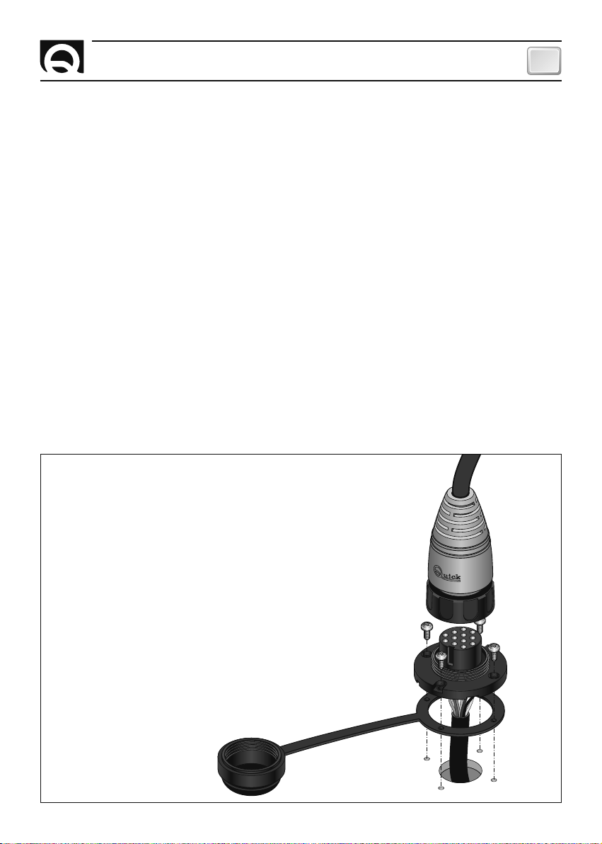
Installing the socket
After selecting the area where the instrument is to be
installed, perform the steps given below:
• Place the drilling template (provided) on the surface where
the socket will be installed.
• Mark the center of each hole.
• Make the hole for the passage of the cable of the socket
with a milling cutter (25 mm / 1").
• Remove the template and any burrs present in the hole.
• Place the seal at the base of the socket.
• Run the cable through the hole made.
• Fix the socket tightening the 4 screws provided.
CHC1102M GB F - REV005B
7
Page 8
GB
INSTALLATION
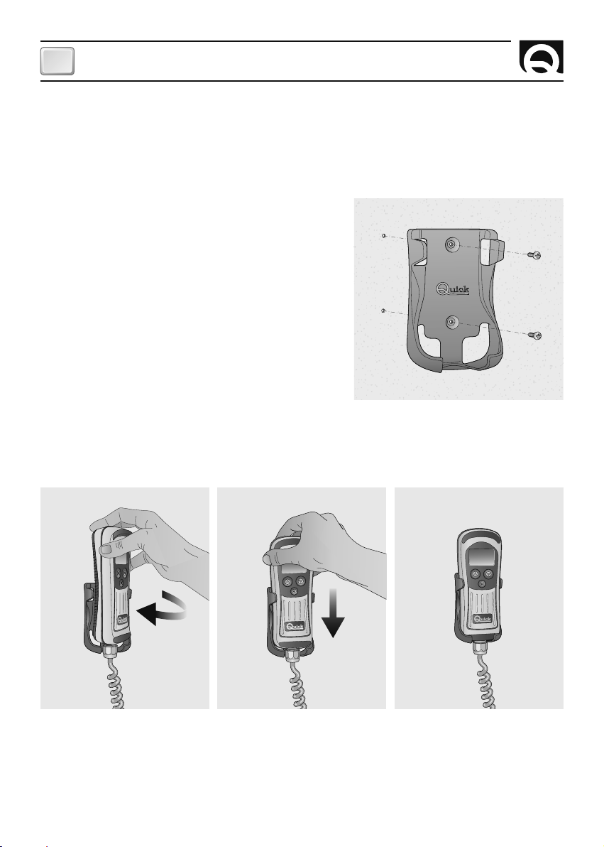
INSTALLING THE SUPPORT
The standard installation procedure is described below. Unfortunately we cannot describe a procedure
applicable to all the situations.
Adapt this procedure to satisfy your own individual requirements.
Find the spot most suitable for the support based on the following criteria:
•
The support must be positioned so that it can easily be
reached by the oper
•
Choose a clean, smooth, flat location.
• Check that the back of the panel into which the screws of
the support will be tightened is free from passing cables
tubes, etc.
• Take particular attention when screwing into the panels or
parts of the boat. The screws must not weaken or cause
the breakage of structure of the boat.
• Place the support onto the chosen surface
• Fix the support with the 2 screws provided.
ator.
,
.
INSERTING THE CHAIN COUNTER INTO THE SUPPORT
To insert the chain counter into the support, follow the instructions in the illustrated sequence:
Insert the chain counter slightly rotated into the support and continue the rotation until the chain counter
is parallel with the support.
Push the chain counter down until it is fully inserted into the support.
8
CHC1102M GB F - REV005B
Page 9
INSTALLATION
GB
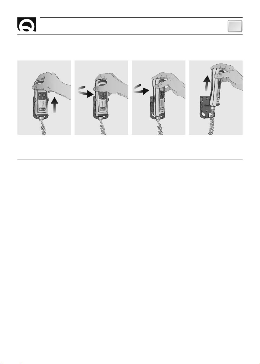
EXTRACTING THE CHAIN COUNTER FROM THE SUPPORT
To extract the control panel from the support, follow the instructions in the illustrated sequence:
Slide the chain counter from its support by raising it a few centimetres, rotate in either direction and then
extract it from the support by raising it.
ELECTRIC CONNECTIONS
The chain counter meets standard EMC (electromagnetic compatibility).
In any case correct installation is fundamental in order not to affect its performance or interfere with operation of instruments found near it.
For this reason the chain counter must be at least:
• 1 m away from cables that transmit radio signals (except for SSB radio transmitters).
• 2 m away from cables for SSB radio transmitter signals.
Follow the safety precautions and directions given below when making the electrical circuit of the chain
counter:
• Turn on power to the chain counter only after having effected and verified that all the electric connections are correct.
• Install a switch to turn on and shut off the chain counter; make sure the switch is in a position that can
be easily reached so that, in the event of an emergency, the chain counter can be quickly shut off.
• Install a 4A fast fuse in the chain counter's power supply line.
• The cross-section of the solenoid/reversing solenoid unit and chain counter's power supply cables
should be adequately sized according to the length of the cables.
• Do not run the chain counter on power delivered from the motors' batteries group.
• Use an unscreened cable with twisted pair (cross-section area 0.25/ 0.35 mm
100/150 ohm) for the data interface connection (CANH and CANL signals).
• The data cable should not be more than 100 meters long.
• The boat's electrical system should allow other switches to operate the windlass.
2
AWG 22/24, impedance
CHC1102M GB F - REV005B
9
Page 10
GB
INSTALLATION
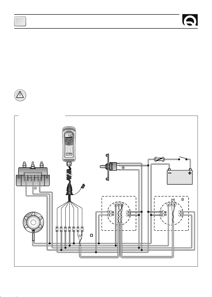
Connecting the instrument
After installing the socket as instructed above, proceed as directed below:
• Turn the cover's ring nut counter-clockwise and take it out.
• Insert the instrument's plug into the socket, being careful to plug it in the right direction.
• Turn the plug's ring nut clockwise until it is fully tightened.
Disconnecting the instrument
• Turn the plug's ring nut counter-clockwise and take it out.
• Cover the socket with the cover provided, turning the ring nut clockwise
ATTENTION: make certain the socket is covered with the cover provided when the instrument is
disconnected.
THE WIRING DIAGRAM
UP ALARM
000 M/M
SPEED
CONTACTOR UNIT/
REVERSING CONTACTOR UNIT
UP DOWN
GYPSY
SENSOR
10
BLEU
BROWN
BLACK
WHITE
GREEN
RED
GREY
150
AUXILIARY
COMMAND
FUSE
4A FAST
UP
DOWN
CHC 1102 M CHC 1102 M
C
A
N
H
CAN L
S
E
N
S
O
R
P
U
DOWN
S
E
N
S
O
R
CHC1102M GB F - REV005B
C
A
N
H
SWITCH
BATTERY
12/24 V
150
CAN L
P
U
DOWN
Page 11
INSTALLATION
GB
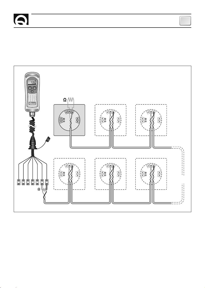
INSTALLING THE TERMINALS
In order for data to be correctly transmitted when several chain counters are employed, terminator (150
ohm) must be installed.
The terminator should be connected between signals CANH and CANL of the first and last chain counter
included in the network, as illustrated in the figure below:
UP ALARM
SPEED 000 M/M
150
C
A
N
SENSOR
1
C
A
N
L
C
A
N
H
P
U
DOWN
H
SENSOR
DOW
20
SENSOR
C
A
N
H
DOWN
C
A
N
H
C
SENSOR
A
19 18 17
N
L
P
BROWN
BLUE
BLACK
WHITE
GREEN
RED
GREY
DOWN
U
150
Do not install the terminator if just one chain counter is used.
C
A
N
23
C
A
N
L
P
U
N
C
A
N
L
P
U
SENSOR
SENSOR
H
C
A
N
L
P
U
DOWN
C
A
N
H
C
A
N
L
P
U
DOWN
INSTRUMENTS
FROM 5 TO 16
CHC1102M GB F - REV005B
11
Page 12

GB
INSTALLATION
CHAIN COUNTER CALIBRATION
Before using the chain counter, either the manual or automatic calibration procedure has to be effected.
The calibration procedure consists of setting the following data: unit of measurement used by the chain
counter, lenght of chain unwound each gypsy lap and number of magnets installed on the gypsy.
To calibrate, go to menu CALIBRATION or AUTO CALIBRATE (see chapter SETTING THE CHAIN COUNTER).
MULTIPLE CHAIN COUNTERS
The chain counter is equipped with a CAN BUS data interface that allows several chain counters to be
connected and information to be exchanged (CAN network).
A MASTER/SLAVE network structure is used, i.e. there is only one main chain counter (MASTER) and all the
other chain counters are secondary (SLAVE).
The network must have at least one MASTER chain counter.
If there is more than one chain counter, instrument CHC1102 M must be set as SLAVE. The instrument
CHC 1102 M should be set as MASTER only if it is the only instrument present.
The task of the MASTER chain counter is to align the length of the chain lowered and the operating
parameters of all the SLAVE chain counters.
The MASTER therefore is used as a reference for all the other SLAVE chain counters.
If a parameter in a menu for a SLAVE chain counter is modified, the change is actually made to the
MASTER chain counter that will automatically update all the SLAVE chain counters (except for menu
PERSONAL SET, UTILITY and CAN CONFIG that cointain particular functions and parameters for every single
chain counter not shared in network with the other chain counters).
The MASTER chain counter should be on even if the commands to the windlass are transmitted from
SLAVE chain counters or other windlass operation switches.
If the MASTER chain counter should malfunction, one of the SLAVE chain counters can be set up as the
MASTER.
Before using the chain counters on the CAN network, make sure the MASTER and SLAVE settings of all
the chain counters are correct and that the network works in a trouble-free manner.
WARNING: If any of the instruments installed has a V2.9x version of the software or later
release also the other instruments should be updated to the V2.9x version or later release.
if in doubt, contact your nearest dealer or Quick
12
®
customer service.
CHC1102M GB F - REV005B
Page 13
CHAIN COUNTER OPERATION
CHAIN COUNTER OPERATION
Three elements are employed between user and counter interface:
A GRAPHIC DISPLAY SCREEN, CONTROL KEYS AND BUZZER.
The graphic display shows the measure of chain lowered, state of the chain counter
along with other information. The control keys comes with three keys. The two largest
keys are used to move the anchor up (
system menus or modify the value of parameters. The middle key (
p
,UP key) or down (q,DOWN key), move within the
=
SELECT) is used to
turn the torch on and off, select the monitoring mode, go to the system menus or confirm
parameters. The buzzer signals when the keys have been pressed or when it is necessary
to call the user's attention. Use the switch on the power supply line to turn the chain
counter on and off.
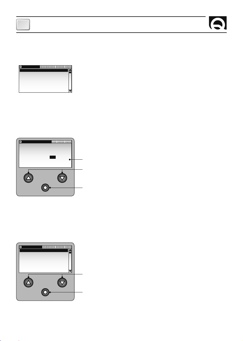
When the chain counter is turned on, the following window is displayed for a few seconds:
Where XXXXX is the serial number, YY is the week of production
and ZZ is the year the chain counter was produced.
When the chain counter is turned on the first time, the menu used to select
CHC1102M
S/N : XXXXX/YYZZ
the language in which messages are displayed appears.
The selected language can be changed later on.
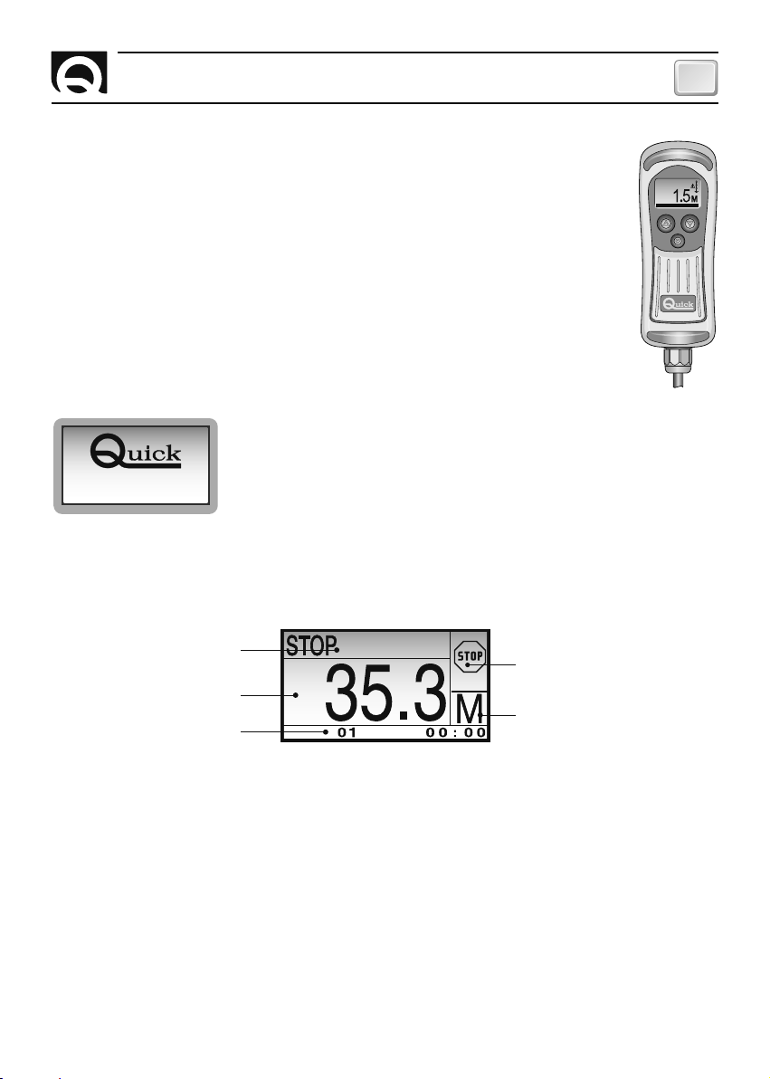
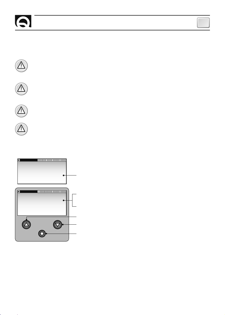
MAIN WINDOW
Once the initialization procedure has been completed, the main window is displayed:
UP ALARM
SPEED 000 M/M
GB
State line
Icon area
Count line
Measure unit area
Monitor line
WED JAN
This window is divided into the following sections:
Count line - The length of the chain lowered is shown in this area.
Measure unit area - The unit of measurement currently being used is shown in this area. The values may
be displayed in "M" for meters and "FT" for feet.
State line - Messages regarding the state of the chain counter or faults detected are shown here.
Icon area - The icons regarding the state of the chain counter or faults detected are shown here.
Monitor line - The following information may be displayed here, depending on the selections made by the
user: date and time, supply voltage, chain speed and winch mode.
CHC1102M GB F - REV005B
13
Page 14
GB
CHAIN COUNTER OPERATION
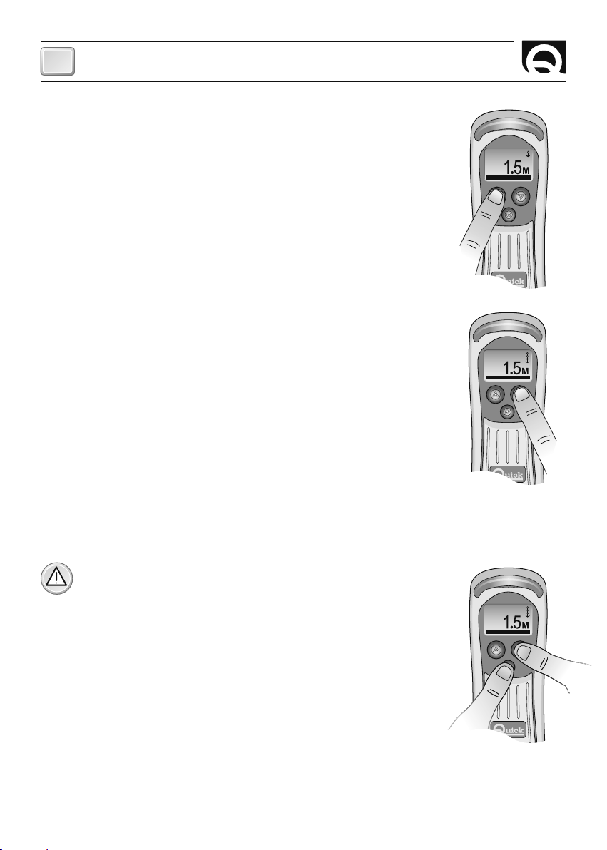
WINDLASS ELECTRIC DRIVE
Getting the anchor aweigh
To get the anchor aweigh press key
anchor reaches the desired position and then release it.
While moving up, the chain counter displays a window similar to the one
shown below:
It is also possible to get the anchor aweigh with an other electric control. The
chain counter will measure the length of the chain lowered in any case.
Lowering the anchor
To lower the anchor press key
anchor reaches the desired position and then release it.
While moving down, the chain counter displays a window similar to the one
shown below:
It is also possible to lower the anchor with an other electric control. The
chain counter will measure the length of the chain lowered in any case.
p
(UP). Hold the key pressed until the
q
(DOWN). Hold the key pressed until the
CHAIN UP
SPEED 20 M/M
CHAIN DOWN
SPEED 20 M/M
Automatic down function
This function can be used only if it was previously set and activated on the FUNCTIONS\AUTO DOWN
menu (see chapter SETTING THE CHAIN COUNTER).
ATTENTION: regular operation of the windlass has to be checked
when moving down automatically
To lower the anchor automatically to the set depth, press keys
and
q
(DOWN) simultaneously for more then three seconds.
=
(SELECT)
AUTO DOWN
SPEED 20 M/M
Once the procedure has started, both keys can be released. The chain
counter will lower the anchor to the set depth.
While moving down automatically, the chain counter displays a window
similar to the one shown below:
The automatic lowering procedure can be interrupted by pressing any key of the chain counter from which the procedure was activated, by activating the up function from an external device (from another chain
counter or other control) or by shutting off the chain counter.
14
CHC1102M GB F - REV005B
Page 15
CHAIN COUNTER OPERATION
GB
Free fall
At times the anchor may have to be lowered by wanting the windlass to free fall (without electrical command).
The chain counter will measure the length of the chain lowered under these circumstances as well. A window similar to the one shown below appears during free fall:
FREE FALL
SPEED 20 M/M
TURNING THE TORCH ON AND OFF
Press and release button = (SELECT) in less than one second to turn on the torch. Press and release button
=
(SELECT) in less than one second to shut off the torch.
When the instrument is turned on, the torch is always off, even if the instrument was shut off from the
power supply with the torch turned on.
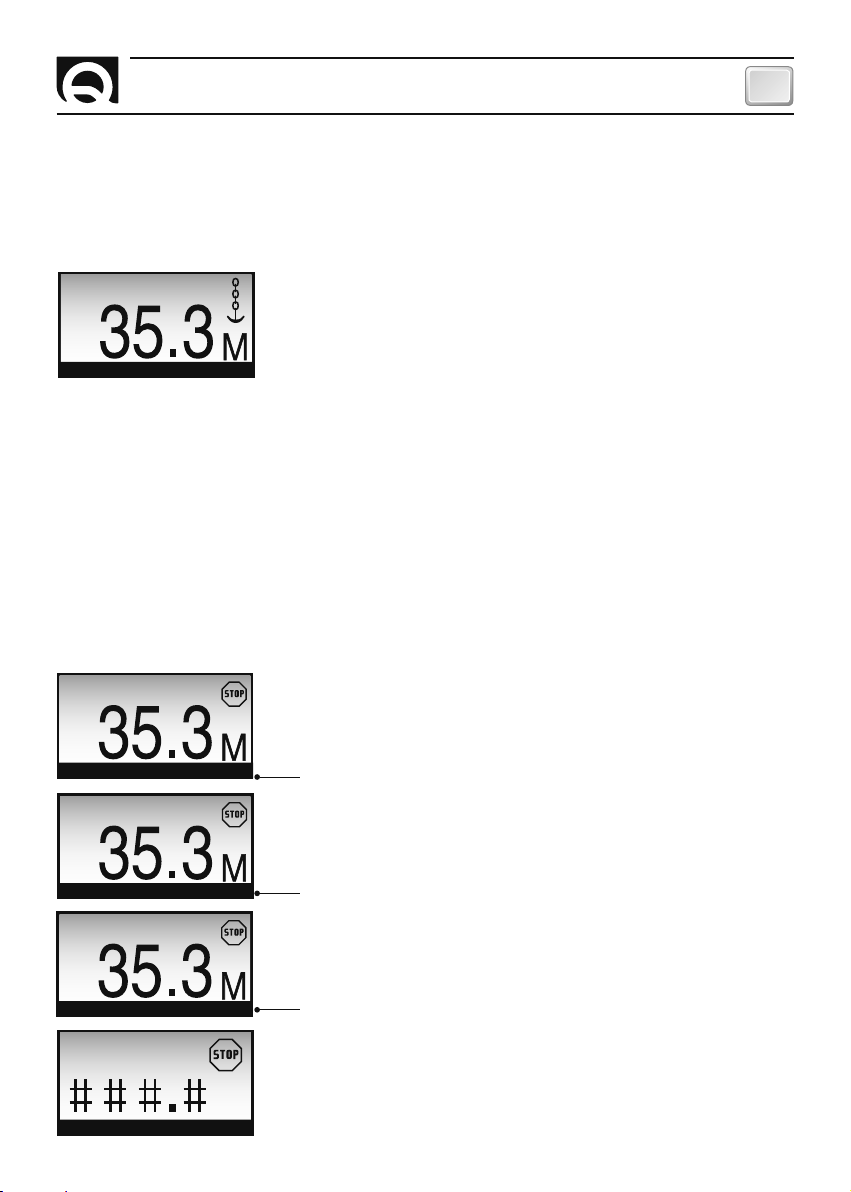
MONITORING
The information given on the monitor line can be edited by pressing and releasing button
within 1 to 3 seconds.
The following data can be displayed: date and time, supply voltage, chain speed and winch mode.
=
(SELECT)
STOP
MON 30 SEP 15:32
STOP
BATTERY 12.8V
STOP
SPEED 0 M/M
STOP
WINCH
CHC1102M GB F - REV005B
The date and time are stored even when the chain counter is shut off
(it is equipped with a backup battery).
The precision of the supply voltage reading is ± 1% accurate.
The precision of the chain speed reading is ±1% accurate.
15
Page 16
GB
CHAIN COUNTER OPERATION
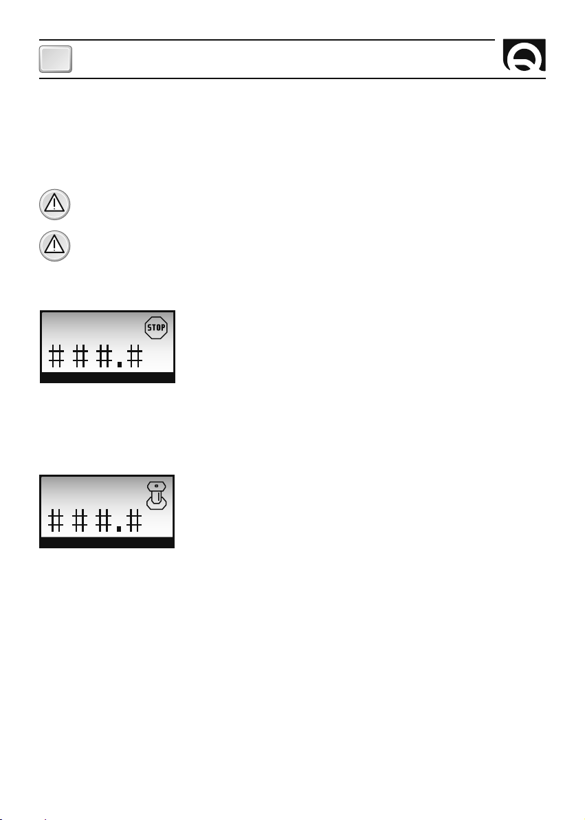
WINCH MODE
This mode must be used when carrying out winch operations with the windlass. In this configuration the
mechanism that moves the chain (gypsy) remains stationary while the drum can still turn.
To use the windlass for winch operations consult relative user manual.
ATTENTION: use this mode only if the windlass is configured for winch operations.
ATTENTION: in this mode the automatic down function is blocked, the up alarm function is
deactivated and the count is not updated.
Once activated the winch mode, the following window is displayed:
STOP
WINCH
To select direction of drum rotation press the
operation is complete, then release the button.
While
p
(UP) or q (DOWN) button is pressed, the instrument will display a window like this:
p
(UP) or q(DOWN) button. Hold the button down until the
ACTIVATED
WINCH
If the instrument is turned off in winch mode, when turned on again it will display the last type of
information selected (date and time, instrument power supply voltage or speed of chain movement).
16
CHC1102M GB F - REV005B
Page 17
SETTING THE CHAIN COUNTER
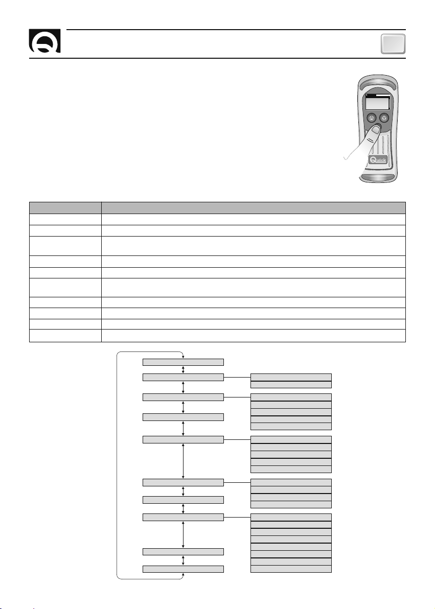
SETTING THE CHAIN COUNTER
The chain counter has a several functions that can be personalized to satisfy user's
requirements.
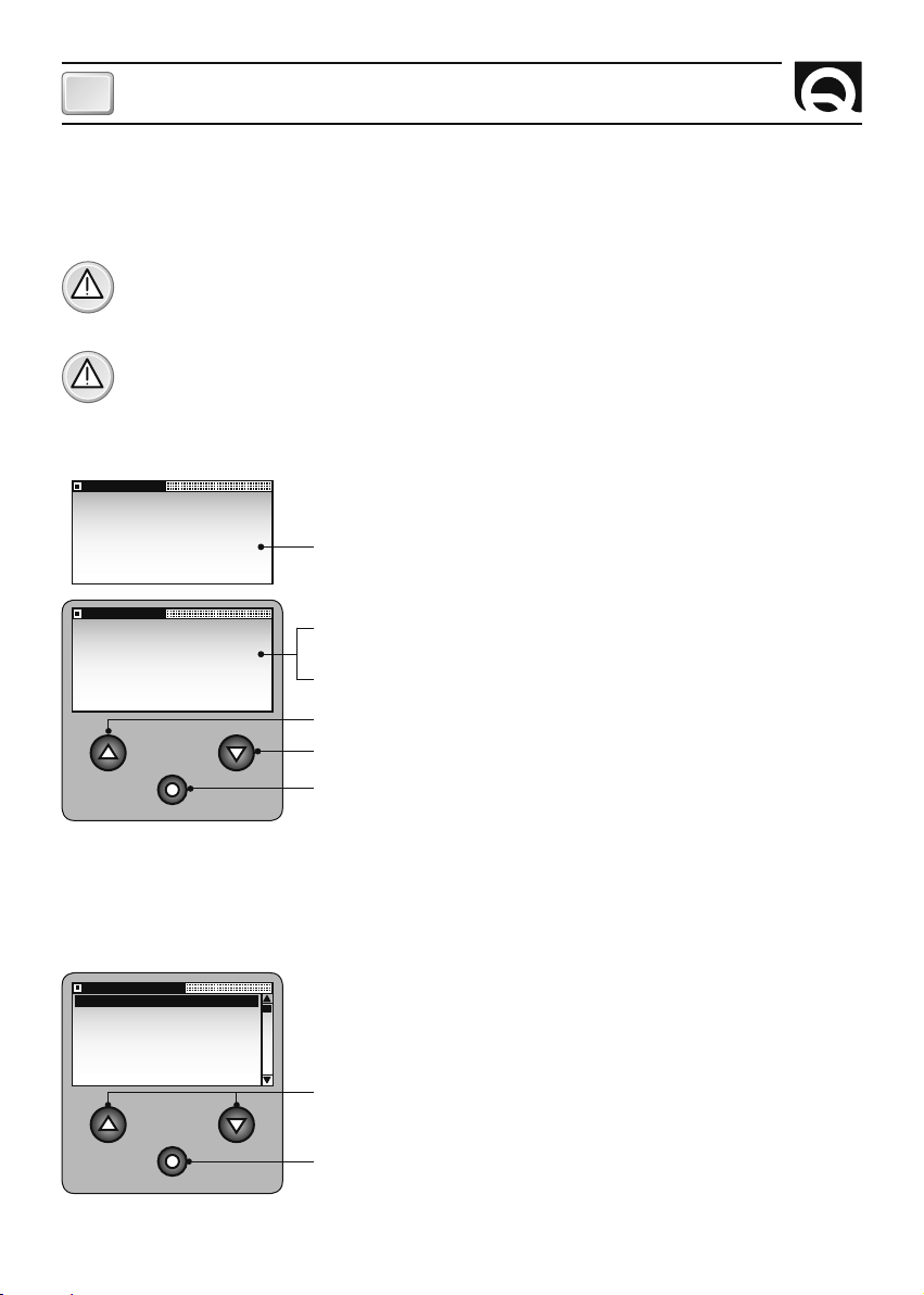
To go to the setting menu, press and release key
start to flash after the button has been pressed)for more than 3 seconds.
As soon as the key is released a window similar to the one shown below is displayed:
Use keys pand q(UP and DOWN) to select the data items within the menu.
The data item that has been currently selected appears in reverse.
Use key
=
(SELECT) to confirm the selected data item.
The following data items are provided on the settings menu, with the MASTER chain
counter present on the network:
DATA ITEM
COUNTER RESET
FUNCTIONS
PERSONAL SET
DATE AND TIME
LANGUAGE
CALIBRATION
AUTO CALIBRATE
UTILITY
CAN CONFIG
EXIT
SYNTHETIC DESCRIPTION
Reset the measure of chain lowered.
Automatic down and up alarm setting.
Chain counter personalization: contrast, back-lighting, light delay, key beep, timed locking of the
DOWN) keys.
System date and time setting.
Language used for system messages.
Chain counter calibration: setting of the measurement unit, of the number of magnets installed, of the gypsy lap on
the gypsy and management of the windlass with free fall.
Automatic chain counter calibration.
Various chain counter controls.
MASTER/SLAVE setting if more than one chain counter is used.
Chain counter set-up menu exit.
=
(SELECT) (the monitoring line will
SETTINGS
COUNTER RESET
FUNCTIONS
PERSONAL SET
DATE AND TIME
LANGUAGE
CALIBRATION
p
and q (UP and
GB
The structure
of the menus:
CHC1102M GB F - REV005B
COUNTER RESET
FUNCTIONS
PERSONAL SET
DATE AND TIME
LANGUAGE
CALIBRATION
AUTO CALIBRATE
UTILITY
CAN CONFIG
EXIT
UP ALARM
AUTO DOWN
CONTRAST
LIGHT
LIGHT DELAY
KEY BEEP
LOCKED KEYS
ENGLISH
ITALIANO
FRANCAIS
DEUTSCH
ESPANOL
SET MEASURE
GYPSY LAP
MAGNETS NUMBER
FREE FALL
SENSOR TEST
LCD TEST
CLOCK BATTERY
SW VERSION
SET DEFAULT
CHECK FLASH
CHECK EEPROM
CAN MESSAGE
17
Page 18
GB
SETTING THE CHAIN COUNTER
If a SLAVE chain counter is being used without the MASTER in the CAN network, the following "reduced"
settings menu will be displayed:
SETTINGS
PERSONAL SET
UTILITY
CAN CONFIG
EXIT
COUNTER RESET
ARE YOU SURE?
YES NO
These submenus have particular parameters and functions for every
single counter which can not be shared with other chain counters present on the CAN network
.
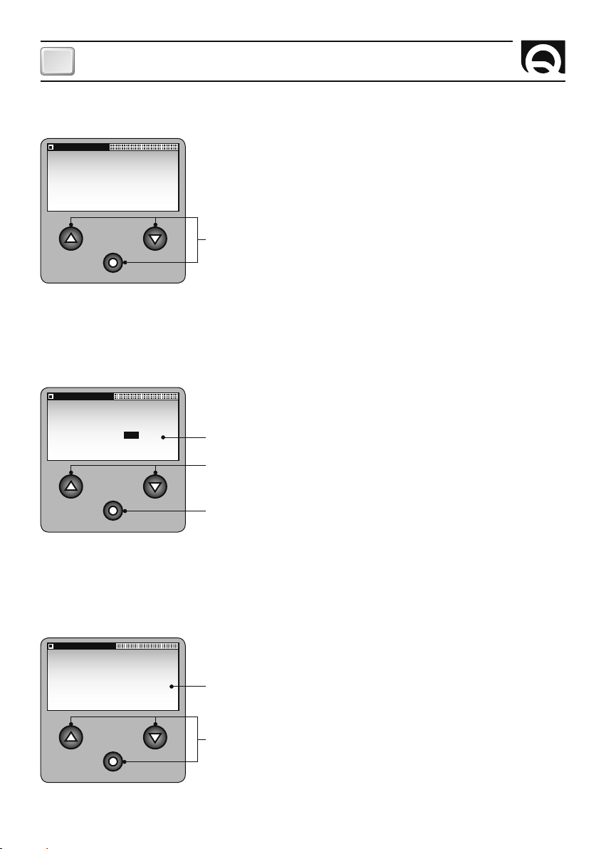
SETTINGS MENU - COUNTER RESET
Use this option to reset the measure of chain lowered.
This option is to be used during installation or when the chain counter's
reading does not match the actual length of the chain lowered.
When this data item is selected, the following window is displayed:
YES or NO can be selected.
Used to select the values available.
Confirm entry and go back to SETTINGS menu.
FUNCTIONS
UP ALARM
AUTO DOWN
EXIT
18
SETTINGS MENU - FUNCTIONS
Use this option to activate and set the up alarms and automatic down.
The sub-menu of the FUNCTIONS option is shown below:
Used to select the data items in the sub-menu.
Press this key to go to the menu shown in REVERSE; if used to EXIT the
system goes back to the SETTINGS menu.
CHC1102M GB F - REV005B
Page 19
SETTING THE CHAIN COUNTER
GB
SETTINGS MENU - FUNCTIONS - UP ALARM
Use this option to set or disable the up alarm. This function stops the anchor from moving up and informs
the user when the length of the chain lowered is less than the set value.
ATTENTION: the up alarm function is active only by using a chain counter CHC 1102 M controls
when the anchor moves up. It does not function if the anchor is moved up by any other remote
control or a switch.
ATTENTION: the chain counter is not able to compensate for mechanical inertia of the windlass
(the gypsy can rotate upward direction as soon as the command has been inactivated). Take this
factor into consideration when setting the up alarm value.
ATTENTION: the alarm is displayed only once, if the chain measure lowered than the alarm threshold.
ATTENTION: even if the up alarm is enabled, the user must always pay careful attention and make
sure the anchor is correctly pulled up.
UP ALARM
SET VALUE:
OFF
UP ALARM
SET VALUE:
1.0 M
CHC1102M GB F - REV005B
Examples of the windows used for the up alarm are shown below:
default: OFF
If the unit of measurement is set to METERS , the settable values are
OFF,
1.0M, 1.5M, 2.0M, 2.5M, 3.0M, 3.5M, 4.0M, 4.5M, 5.0M.
If the unit of measurement is set to FEET, the settable values are
OFF, 3.0FT,
4.5FT, 6.0FT, 7.5FT, 9.0FT, 10.5FT, 12.0FT, 13.5FT, 15FT.
Increase value
Decrease value
Confirm value and go back to FUNCTIONS menu.
19
Page 20
GB
SETTING THE CHAIN COUNTER
SETTINGS MENU - FUNCTIONS - AUTOMATIC DOWN
The automatic down function is enabled or disabled with this option. This function allows the anchor to
automatically move down to the set depth (see chapter CHAIN COUNTER OPERATION paragraph AUTOMATIC DOWN FUNCTION).
ATTENTION: the chain counter is not able to compensate for mechanical inertia of the windlass
(the gypsy can rotate downward direction as soon as the command has been inactivated). Take
this factor into consideration when setting the automatic down value.
ATTENTION: even if the automatic down function is enabled, the user must always pay careful
attention and make sure the anchor is correctly lowered.
AUTO DOWN
SET VALUE:
AUTO DOWN
SET VALUE:
PERSONAL SET
CONTRAST
LIGHT
LIGHT DELAY
KEY BEEP
LOCKED KEYS
EXIT
OFF
5 M
Examples of the windows used for the automatic down function are
shown below:
default: OFF
If the unit of measurement is set to METERS, the settable values are
OFF,
from 5M to 100M with 5M steps.
If the unit of measurement is set to FEET, the settable values are OFF,
from
15FT to 300F with 15FT steps.
Increase value
Decrease value
Confirm value and go back to FUNCTIONS menu.
SETTINGS MENU
PERSONAL SET
This option allows the user to enable and set several functions to personalize the chain counter.
The PERSONAL SET sub-menu is shown below.
Selects the data items in the sub-menu.
20
Press this key to go to the menu shown in REVERSE; if EXIT has been
selected the system goes back to the SETTINGS menu.
CHC1102M GB F - REV005B
Page 21

CONTRAST
LIGHT
SET VALUE:
4
SET VALUE:
4
SETTING THE CHAIN COUNTER
GB
SETTINGS MENU - PERSONAL SET
CONTRAST
Use this option to adjust the contrast of the LCD. The change is immediately made without having to confirm the value.
Selectable values: 1, 2, 3, 4, 5, 6, 7, 8. (default: 4).
Increase value
Decrease value
Confirm value and go back to PERSONAL SET menu.
SETTINGS MENU - PERSONAL SET
LIGHT
Use this option to adjust the back-lighting of the display screen.
The brightness is immediately changed without having to confirm the
value.
Selectable values: OFF,1, 2, 3, 4, 5, 6, 7, 8. (default: 4).
Increase value
Decrease value
Confirm value and go back to PERSONAL SET menu.
LIGHT DELAY
SET VALUE:
30S
CHC1102M GB F - REV005B
SETTINGS MENU - PERSONAL SET
LIGHT DELAY
Use this option to set the delay time for shutting off the back-lighting
of the display screen. The delay time starts to elaps as soon as the last
key is released (or when FREE FALL is completed).
Selectable values: 30S, 60S, 90S, 120S, 180S, 240S, ON
(always on). (default: 30S).
Increase value
Decrease value
Confirm value and go back to PERSONAL SET menu.
21
Page 22

GB
SETTING THE CHAIN COUNTER
SETTINGS MENU - PERSONAL SET
KEY BEEP
Use this option to activate or deactivate the beep that sounds whene-
KEY BEEP
SET VALUE:
YES NO
ver a key is pressed.
Selectable options: YES and NO. (default: YES).
Select the values available.
Confirm value and go back to PERSONAL SET menu.
SETTINGS MENU - PERSONAL SET
LOCKED KEYS
This function is used to set the time for the locking of the
LOCKED KEYS
SET VALUE:
4 min
and DOWN) keys. Once the set time has elapsed, from the moment it
finds itself in stop status, the instrument goes into locked keys status.
Select the available values: OFF, 1min, 2min, 3min, 4min, 5min, 6min,
7 min, 8min, 9min, 10min. (default: OFF)
Increase value
Decrease value
Confirm value and go back to PERSONAL SET menu.
p
and q (UP
DATE AND TIME
22
2003 JAN 03
00:00
EXIT
SETTINGS MENU
DATE AND TIME
Use this option to set the clock and calendar.
The DATE AND TIME window appears as follows:
Increase value
Decrease value
Confirm value and go to next parameter; if EXIT has been selected the
system goes back to SETTINGS menu.
CHC1102M GB F - REV005B
Page 23

LANGUAGE
ENGLISH
ITALIANO
FRANCAIS
DEUTSCH
ESPANOL
CALIBRATION
SET MEASURE
GYPSY LAP
MAGNETS NUMBER
FREE FALL
EXIT
SETTING THE CHAIN COUNTER
GB
SETTINGS MENU
LANGUAGE
Use this option to select the language in which the system messages
are displayed.
The LANGUAGE sub-menu appears as shown below.
Select the data items.
Confirm value and go back to SETTINGS menu.
SETTINGS MENU
CALIBRATION
Use this option to calibrate the chain counter according to the windlass
it is mounted on.
The CALIBRATION sub-menu appears as follows:
Select the data items in the menu.
SET MEASURE
SET VALUE:
METERS FEET
CHC1102M GB F - REV005B
Confirm value and go to next parameter; if EXIT has been selected the
system goes back to SETTINGS menu.
SETTINGS MENU - CALIBRATION
SET MEASURE
Use this option to select the unit of measurement relative to measurement of chain lowered.
Selectable options: METERS or FEET. (default: METERS).
Select the values available.
Confirm value and go back to CALIBRATION menu.
23
Page 24

GB
SETTING THE CHAIN COUNTER
SETTINGS MENU - CALIBRATION - GYPSY LAP
Use this option to set the measurement of the chain in one gypsy lap. To obtain this value, remove the
gypsy, wind the chain around it and then measure its length.
Consult the User's
manual of the windlass
for more detailed
GYPSY LAP
instructions on how to
remove and re-install the
gypsy.
It is extremely important that the value set for GYPSY LAP is precise as it affects the
accuracy with which the length of the lowered chain is measured
GYPSY LAP
SET VALUE:
10.0 CM
If the unit of measurement is set to METERS, the settable values are
from 0.1 to 999.9 cm (default: 10 cm).
Increase value
Decrease value
Confirm value and go back to CALIBRATION menu.
GYPSY LAP
MAGNETS NUMBER
24
SET VALUE:
10.0 INC
SET VALUE:
1
If the unit of measurement is set to FEET, the settable values are from
0.1 to 999.9 inch (default: 10 inch).
SETTINGS MENU - CALIBRATION - NUMBER OF MAGNETS
Use this option to set the number of magnets installed on the gypsy.
Selectable Values: 1 to 16. (default: 1).
Increase value
Decrease value
Confirm value and go back to CALIBRATION menu.
CHC1102M GB F - REV005B
Page 25

FREE FALL
SET VALUE:
0,5 s
SETTING THE CHAIN COUNTER
GB
SETTINGS MENU - CALIBRATION
AUTO FREE FALL
Through this management we set the time required by the windlass
auto free fall system to deactivate itself.
Select the available values: OFF, from 0.1s to 7s. (default: OFF)
Increase value
Decrease value
Confirm value and go back to CALIBRATION menu.
SET SAILFREE FALL
UP ALARM
SPEED 000 M/M
0.1s-7s
ATTENTION: auto free fall management must be activated exclusively with windlasses equipped
with auto free fall system. Refer to the instruction manual relative to the windlass being used.
ATTENTION: If auto free fall management is activated, the "no sensor" signal time will vary
depending on the value entered in the AUTO FREE FALL parameter and the automatic descent
function will be deactivated; the latter will become active again once free fall management is
deactivated.
CHC1102M GB F - REV005B
25
Page 26

GB
SETTING THE CHAIN COUNTER
SETTINGS MENU - AUTOMATIC CALIBRATION
Use this option to automatically calibrate the chain counter.
The first window regarding AUTOMATIC CALIBRATION is shown below:
AUTO CALIBRATE
SET VALUE:
METERS FEET
EXIT
Use this option to select the unit of measurement used to measure the
chain lowered. Selectable values: METERS or FEET.
Select the values available.
Confirm value and go to next window for AUTOMATIC CALIBRATION
procedure, if EXIT is selected the system goes back to menu SETTINGS.
AUTO CALIBRATE
PRESS
UNTIL 6M
DEPTH
PRESS
TO EXIT
This window tells the user the chain has to be lowered 6 meters (or 20
feet, depending on the unit of measurement selected) in an uninterrupted manner. The length of the chain unwound each lap can be calcula-
AUTO CALIBRATE
PRESS
UNTIL 20FT
DEPTH
PRESS
TO EXIT
ted according to the number of laps completed by the gypsy (counted
by the chain counter).
Not active
Chain down; it counts the number of gypsy laps.
Cancel procedure and go back to SETTINGS menu.
Once key q (DOWN) is released the chain counter will stop the chain from moving down and automatically set the following values:
CM=600/number of laps counted
GYPSY LAP
NUMBER OF MAGNETS=1
CM=240/number of laps counted
GYPSY LAP
NUMBER OF MAGNETS=1
After which the following window will be displayed for two seconds:
AUTO CALIBRATE
END OF
PROCEDURE
26
And the SETTINGS menu will be shown again.
CHC1102M GB F - REV005B
Page 27

SETTING THE CHAIN COUNTER
GB
UTILITY
SENSOR TEST
LCD TEST
CLOCK BATTERY
SW VERSION
SET DEFAULT
CHECK FLASH
UTILITY
SW VERSION
SET DEFAULT
CHECK FLASH
CHECK EEPROM
CAN MESSAGE
EXIT
SENSOR TEST
SENSOR STATUS:
ON
SENSOR TEST
SENSOR STATUS:
OFF
SETTINGS MENU
UTILITY
This option allows the user to perform procedures to check and control
the chain counter operation.
The UTILITY sub-menu appears as shown below:
Select data items from sub-menu
Press this key to go to the menu shown in REVERSE; if EXIT has been
selected the system goes back to the SETTINGS menu.
SETTINGS MENU - UTILITY
SENSOR TEST
This function can be used during installation or to check that the
lap sensor works properly. If the sensor detects the magnet, ON is
displayed and the buzzer sounds; otherwise OFF is displayed and the
buzzer does not sound.
Go back to UTILITY
SETTINGS MENU - UTILITY - LCD TEST
This function can be used to check correct operation of the LCD display's pixels.
Once the data item has been confirmed from the utility menu, all the display pixels will be activated for 5
seconds; after which the system will go back to menu UTILITY.
CLOCK BATTERY
SETTINGS MENU - UTILITY
CLOCK BATTERY
CLOCK BATTERY
X.XX VDC
This function displays the voltage of the clock's backup battery.
Go back to UTILITY menu.
CHC1102M GB F - REV005B
27
Page 28
GB
SETTING THE CHAIN COUNTER
SETTINGS MENU - UTILITY
SW VERSION
SW VERSION
SW VERSION
VX.XX
This function displays the software version installed in the chain
counter.
Go back to UTILITY menu.
SETTINGS MENU - UTILITY
SET DEFAULT
This function allows the user to enter the default values and restart the
SET DEFAULT
ARE YOU SURE?
YES NO
chain counter.
The SET DEFAULT window appears as shown below:
YES or NO can be entered.
Select data items from sub-menu.
CHECK FLASH
28
CHECK FLASH
TRUE: XXXX
SUM: YYYY
Confirm value.
SETTINGS MENU - UTILITY
CHECK FLASH (PROGRAM MEMORY)
This function shows the calculated FLASH memory checksum (SUM)
and the one stored during production (TRUE).
In order for the chain counter to operate properly the two values must
match.
Go back to UTILITY menu.
CHC1102M GB F - REV005B
Page 29

CHECK EEPROM
CHECK EEPROM
TRUE: XXXX
SUM: YYYY
CAN MESSAGE
TX MSG: 000
RX MSG: 000
LAST ID: 000
CAN UPD: 000
SETTING THE CHAIN COUNTER
GB
SETTINGS MENU - UTILITY
CONTROL EEPROM (DATA MEMORY)
This function shows the calculated EEPROM memory checksum (SUM)
and the one stored (TRUE).
In order for the chain counter to operate properly the two values must
match.
Go back to UTILITY menu.
SETTINGS MENU - UTILITY
CAN MESSAGE
This function shows some information regarding CAN messages transmission state.
CAN CONFIG
SET VALUE:
MASTER SLAVE
CHC1102M GB F - REV005B
Go back to UTILITY menu.
SETTINGS MENU
CAN CONFIGURATION
This option allows the user to determine chain counter's priority in the
CAN network (see chapter MULTIPLE CHAIN COUNTERS).
MASTER and SLAVE can be entered (default: MASTER).
Select the values available.
Confirm entry and go back to SETTINGS menu.
29
Page 30

GB
SYSTEM ERRORS AND FAULTS
SYSTEM ERRORS
System errors may arise when the chain counter chain counter is turned on.
Checksum error
The following windows are displayed if the chain counter detects an error in the memorized data:
CONTROL CHECKSUM
FLASH CHECKSUM
ERROR
TRUE: XXXX
SUM: YYYY
CONTROL EEPROM
EEPROM CHECKSUM
ERROR
TRUE: XXXX
SUM: YYYY
EEPROM memory checksum errorFLASH memory checksum error
If one of these messages appears do not use the chain counter and contact a service center or QUICK
customer service without delay.
Multi Master error
If the chain counter detects more then one of MASTER chain counters in
the CAN network, the following window is displayed:
Select chain counter's priority in the CAN network
(see chapter MULTIPLE CHAIN COUNTERS).
MULTI MASTER
ERROR
SET VALUE:
MASTER SLAVE
®
SYSTEM FAULTS
System faults that appear on the state line divided into three categories which are shown below: problems with automatic reset, problems with automatic reset and keys locked and problems with manual
reset.
PROBLEMS WITH AUTOMATIC RESET
These faults are automatically reset as soon as the cause that had generated the problem disappears.
Low voltage
This fault is displayed if the voltage drops below 10.5Vdc for more than
one second. Reset takes place if the voltage is higher than 11.0Vdc for
more than one second. Check the charge level of the batteries that supply
voltage or the electrical system.
The window shown below appears when this problem is present:
LOW VOLTAGE
SPEED 0 M / M
Clock battery low
This fault is displayed if the voltage of the clock battery drops below
2.80Vdc. The chain counter checks the battery voltage when turned on and
every half hour. The problem is reset if the voltage is higher than or equal
CLOCK BAT LOW
to 2.80Vdc. The clock battery can be replaced only at an authorized service
center.
The window shown below appears when this problem is present:
30
SPEED 0 M / M
CHC1102M GB F - REV005B
Page 31

SYSTEM FAULTS
GB
NO MASTER
This fault is displayed if there is not a chain counter with MASTER priority
in the CAN network (see chapter MULTIPLE CHAIN COUNTERS). See if the
NO MASTER
MASTER chain counter is on and the data line connections.
The window shown below appears when this problem is present:
SPEED 0 M / M
CAN BUS communication error
This fault is displayed if there are errors that cannot be recovered during
CAN ERROR
CAN network communication.
Make sure the data cables are properly connected.
The window shown below appears when this problem is presen
t:
SPEED 0 M / M
PROBLEMS WITH AUTOMATIC RESET AND KEYS LOCKED
These faults are automatically reset as soon as the cause that had generated the problem disappears.
Some keys are disabled when these faults are present.
Opposed commands
This fault is displayed if keys UP or DOWN are pressed at the same time as
the respective external control DOWN or UP key (other chain counters or
OPPOSED
other remot switch).
If the fault is present keys
The window shown below appears when this problem is present:
p,q
(UP, DOWN) are disabled.
SPEED 0 M / M
Overload
This fault is signaled when the instrument detects at short circuit or overload at the instrument's output.
Check wiring of signals UP and DOWN and absorption of the points of use
OVERLOAD
connected to the instrument's output.
If a fault is present, keys
A window similar to the one shown below appears if a fault is present:
p,q
(UP, DOWN) are inoperative.
SPEED 0 M / M
Remote programming active
This fault is displayed if a chain counter has entered the SETTINGS menu in
the CAN network (see chapter MULTIPLE CHAIN COUNTERS). Wait until the
REMOTE PROG
chain counter has exit the menu.
If the fault is present key
The window shown below appears when this problem is present:
CHC1102M GB F - REV005B
=
(SELECT) is disabled
SPEED 0 M / M
31
Page 32

GB
SYSTEM FAULTS
PROBLEMS WITH MANUAL RESET
These problems are reset by the user: by pressing key
it back on. If the fault is present keys
p, q (UP, DOWN) are disabled.
=
(SELECT) or turn off the chain counter and turn
Up alarm
This fault is displayed if the length of the chain is less than the value set on
the FUNCTIONS\UP ALARM menu.
The window shown below appears when this problem is present:
No laps sensor
This fault is displayed if the laps sensor does not detect the gypsy movement within four seconds (for a longer time if auto free fall management is
activated) when key
switches are pressed.
Check the distance between the magnet and sensor, operation of the laps
sensor and the wiring/connections.
The window shown below appears when this problem is present:
Sensor failure
This fault is displayed if the chain counter detects a short circuit in the
sensor for more than four seconds (for a longer time if auto free fall management is activated) when key
or other switches are pressed.
Check operation of the laps sensor and the wiring/connections.
The window shown below appears when this problem is present:
p or q
(UP or DOWN ) of the chain counter or other
p
or q
(UP or DOWN ) of the chain counter
UP ALARM
SPEED 0 M / M
NO SENSOR
SPEED 0 M / M
SENSOR FAILUR
SPEED 0 M / M
CONFIRMATION MESSAGES
Confirmation messages that may appear on the state line are shown below.
STOP
Stop
When no commands are sent to the windlass, the following window is displayed:
SPEED 0 M / M
Memory stored
As soon as four seconds elapsed from the last operation was completed
(up, down, automatic down, free fall), the chain counter stores the length of
the lowered chain in the EEPROM memory.
The window shown below is displayed while the data are being saved:
Locked Controls
Once the time set in the LOCKED KEYS parameter has elapsed, the instrument will inhibit the functionality of the
pressing these keys will have no effect. Pressing the
reactivate the functionality of the
32
p
and q and (UP and DOWN) keys;
=
key (SELECT) will
p
and q (UP and DOWN) keys.
MEMORY STORED
SPEED 0 M / M
LOCKED
SPEED 0 M / M
CHC1102M GB F - REV005B
Page 33
MAINTENANCE - TECHNICAL DATA
GB
MAINTENANCE
The chain counter does not require any particular maintenance. To assure top performance, check the
cables and electrical connections once a year.
Clean the chain counter with a soft rag dampened in water. Do not use chemicals or harsh products to
clean the chain counter.
TECHNICAL DATA
MODELS CHC 1102 M
OUTPUT CHARACTERISTICS
UP/DOWN contacts current 4A max
INPUT CHARACTERISTICS
Supply voltage (1) from 9 to 30 Vdc
Current absorbed when idling (2) 40 mA
Maximum current absorbed (3) 165 mA + current used by solenoid/reversing solenoid unit
AMBIENT CHARACTERISTICS
Operating temperature (4) -20 ÷ +70 °C
Degree of protection (5) IP 67
GENERAL
Communication interface CAN BUS with differential transceiver
Clock battery CR2032 (3Vdc)
EMC class EN 60945 - FCC Part 15 Rules 47
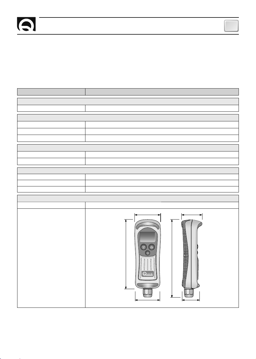
CASE
Weight 750 g
62.2 49.4
Dimensions (WxHxD)
62.2 x 185 x 49.4 mm
(1) The chain counter can reset itself if the voltage is less than 9 Vdc.
(2) Typical value with back-lighting and torch off and windlass not on.
(3) Typical value with back-lighting on at highest level and windlass on.
(4) With temperatures below 0°C the crystals in the LCD slow down.
(5) Except for the area where the electric contacts are connected (IP 00).
®
QUICK
RESERVES THE RIGHT TO MODIFY THE TECHNICAL CHARACTERISTICS OF THE EQUIPMENT AND THE CONTENTS OF THIS MANUAL WITHOUT PRIOR NOTICE.
CHC1102M GB F - REV005B
165
185
59.1 41.6
33
Page 34

FR
CARACTÉRISTIQUES ET INSTALLATION
COMPTEUR DE CHAÎNE CHC 1102 M
Notre expérience acquise dans le domaine nautique nous a permis de fabriquer le compteur de chaîne,
désigné CHC 1102 M, qui offre des performances supérieures par rapport aux autres appareils sur le
marché. L'équipement CHC 1102 M permet d'actionner le guindeau pour monter ou descendre l'ancre en
indiquant la longueur de la chaîne mouillée.
Les autres avantages du compteur de chaîne CHC 1102 M sont:
• Interface utilisateur simple et facile à comprendre.
• Messages affichés en 5 langues.
• Descente automatique.
• Message d'anomalie pendant la montée.
• Fonction touches bloque.
• Gestion des guindeaux avec chute libre automatique.
• Egalement utilisable dans les opérations de poupée seule.
• Affichage de la vitesse de déplacement de la chaîne.
• Indication de la tension d'alimentation.
• Horloge/date.
• Indication de la longueur de la chaîne descendue (en mètres ou pieds).
• Afficheur graphique LCD avec grand angle de vision.
• Le rétro éclairage de l'afficheur peut être réglé sur huit intensités différentes.
• Le contraste de l'afficheur peut être réglé à huit niveaux.
• Compensation automatique du contraste de l'afficheur selon la température ambiante.
• Alimentation électrique universelle (12/24Vdc).
• Boutons rétro-éclairés.
• Pourvu de torche à led.
• Interface CAN BUS pour le transfert des données.
• Fonctionnement sur une gamme de températures ambiantes.
• Boîtier étanche.
INSTALLATION
AVANT D'UTILISER LE COMPTEUR DE CHAINE, LIRE ATTENTIVEMENT CE MANUEL UTILISATEUR.
DANS LE DOUTE, CONSULTER LE REVENDEUR QUICK
En cas de discordances ou d’erreurs éventuelles entre la traduction et le texte original en italien, se
F
référer au texte italien ou anglais.
Ce dispositif a été conçu et réalisé pour être utilisé sur des bateaux de plaisance.
F
Tout autre emploi est interdit sans autorisation écrite de la société Quick
Le compteur de chaîne Quick® a été conçu et fabriqué pour les buts décrits dans ce manuel d'utilisation.
La Société Quick
installation et utilisation de l'appareil ainsi que des erreurs décrites dans ce manuel.
®
n'est responsable d'aucun dommage direct ou indirect provoqué par une mauvaise
®
.
®
.
LA RÉPARATION DU COMPTEUR DE CHAINE PAR DU PERSONNEL NON AUTORISÉ ENTRAÎNE
L'ANNULATION DE LA GARANTIE.
L'EMBALLAGE CONTIENT: compteur de chaîne - support - prise - kit capteur de proximité - résistance de
terminaison 150 ohm - joint - vis pour la fixation de la prise - gabarits de perçage - conditions de garantie
- manuel d'utilisation.
34
CHC1102M GB F - REV005B
Page 35

INSTALLATION
FR
LE MONTAGE DU COMPTEUR DE CHAÎNE S'EFFECTUE EN TROIS PHASES:
Montage du capteur de proximité sur le guindeau, montage de l'instrument sur les parois et connexions
électriques.
Guindeaux Quick®
Tous les guindeaux Quick® sont équipés d'un capteur de proximité qui doit être utilisé avec le compteur
de chaîne CHC 1102 M.
Autres guindeaux
Le compteur de chaîne compte le nombre de tours du barbotin pour mesurer la longueur de la chaîne
descendue. Le capteur de proximité, fourní avec l'appareil, se compose d'un aimant cylindrique et de
deux adaptateurs pour le montage du capteur.
L'aimant doit être relié au barbotin tandis que le capteur magnétique doit être placé à la base du
guindeau.
La procédure de montage standard est décrite ci-dessous. On ne peut pas fournir une procédure qui peut
être utilisée pour tous les guindeaux.
EXAMPLES D' INSTALLATION AVEC CAPTEUR DE VITESSE
Guideau à axe vertical
1
AIMANT
Guindeau à axe horizontal
Max. 10 mm
CHC1102M GB F - REV005B
Max. 10 mm
Installation
idéale
11
22
2
2
3
3
± 20°
11
22
22
44
Ecartement
max
2
CAPTEUR
3
ADAPTATEUR
4
ADAPTATEUR
35
Page 36

FR
INSTALLATION
MONTAGE DE L'AIMANT
Retirer le barbotin du guindeau (consulter le manuel d'utilisation du guindeau). Etablir la position la plus
adéquate pour loger l'aimant selon les critères d'instructions fournies ci dessous:
• Le logement doit se trouver dans une zone où la chaîne ne passe pas (à l'extérieur).
• Le logement doit être dans la zone où le barbotin est plus épais (Afin de ne pas affaiblir la
structure)
• Si l'axe du guindeau est horizontal, s'assurer que le logement est proche du bord du barbotin.
• Si l'axe du guindeau est vertical, s'assurer qu'on peut monter le capteur sur l'embase dans le champ
magnétique de l'aimant.
• Si l'aimant dépasse du barbotin; s'assurer qu'il ne heurte pas l'embase ou le capteur.
• La distance entre l'aimant et le capteur doit être la plus courte possible.
Créer le logement en perçant un trou du même diamètre que l'aimant, coller l'aimant à l'intérieur.
Faire en sorte que la colle couvre la partie visible de l'aimant. Utiliser une colle capable de résister
à des températures de -30 à +80°C et à l'eau de mer. On conseille d'utiliser des colles époxy à deux
composants.
On peut installer plusieurs aimants sur le même barbotin pour augmenter la précision de l'instrument
(don fournis) Placer les aimants le long de la même circonférence et à la même distance entre eux.
MONTAGE DU CAPTEUR
Déterminer la position la plus appropriée pour le montage du capteur. La procédure doit être effectuée en
suivant les instructions ci-dessous:
• Le capteur doit être installé loin du point où la chaîne passe.
• Si on perce des trous sur l'embase qui pourraient avoir des effets sur le fonctionnement, rendre la
structure plus faible ou provoquer l'écoulement du lubrifiant (guindeaux avec engrenages en bain
d'huile).
• Si l'axe du guindeau est vertical, s'assurer que le capteur est monté sur l'embase au niveau du champ
magnétique engendré par l'aimant placé sur le barbotin.
• La distance entre l'aimant et le capteur doit être la plus petite possible.
Utiliser les adaptateurs en plastique fournis pour fixer le capteur. Protéger les câbles du capteur en
utilisant des gaines adéquates.
Une fois l'installation complétée, contrôler le capteur de proximité en positionnant le barbotin de manière
à ce que l'aimant soit aligné avec le capteur. Dans cette position le courant passe entre les deux fils. Si on
éloigne l'aimant, le courant ne doit plus passer.
36
CHC1102M GB F - REV005B
Page 37

INSTALLATION
FR
INSTALLATION DE LA PRISE
La procédure type du montage est décrite ci-dessous. Il est impossible de fournir une procédure standard
utilisable pour toutes les situations. Il faut donc adapter cette procédure à vos exigences spécifiques.
Déterminer la position la plus adéquate pour loger l'appareil et suivre les instructions ci-dessous:
• La prise doit être installée de manière à pouvoir être facilement accessible par l'opérateur.
• Choisir un emplacement qui soit propre, lisse et à plat.
• Il doit y avoir un accès postérieur au plan de fixation de la prise pour l'installation et l'entretien.
• Il doit y avoir un espace suffisant au dos de la position choisie pour laisser un passage libre pour le
câble de la prise.
• La partie arrière de la prise doit être protégée de tout contact avec l'eau ou l'humidité.
• Faire particulièrement attention lors de la réalisation de l'orifice sur le panneau ou certaines parties de
l'embarcation. Cet orifice ne doit pas affaiblir ou pouvoir causer la rupture de la structure de l'embarcation.
Le compteur de chaîne est conforme aux normes EMC (compatibilité électromagnétique). Il doit être bien
installé afin de ne pas réduire ses performances ainsi que celles des instruments montés à proximité.
Pour cette raison-là, l'appareil doit se trouver a une distance minimum de:
• 25 cm du compas
• 25 cm de tout appareil radio récepteur
• 1 m de tout appareil radio de transmission (excepté SSB)
• 2 m de tout appareil radio de réception et transmission SSB
• 2 m du parcours suivi du faisceau radar.
Installation de la prise
Après avoir choisi l'emplacement de l'instrument, procéder
comme indiqué ci dessous:
• Positionner le gabarit de perçage (fourni avec l'équipement)
sur la superficie où sera installée la prise.
• Marquer le centre de chaque orifice.
• Percer l'orifice destiné au passage du câble de la prise en
utilisant une fraise d'un diamètre de 25 mm (1").
• Enlever le gabarit et les éventuelles bavures présentes sur
l'orifice.
• Disposer le joint sur la base de la prise.
• Introduire le câble dans l'orifice réalisé.
• Fixer la prise en vissant les 4 vis fournies avec l'équipement.
CHC1102M GB F - REV005B
37
Page 38

FR
INSTALLATION
INSTALLATION DU SUPPORT
La procédure type du montage est décrite ci-dessous. Il est impossible de fournir une procédure standard
utilisable pour toutes les situations. Il faut donc adapter cette procédure à vos exigences spécifiques.
Déterminer la position la plus adéquate pour loger le support et suivre les instructions ci-dessous:
• Le support doit être placé de façon à être facilement
accessible par l'opérateur.
• Choisir une position propre, lisse et plate.
• Vérifier qu'il n'y a pas de câbles, de tuyaux, etc., qui
passent dans la partie postérieure du panneau sur
lequel les vis du support seront vissées.
• Faire particulièrement attention quand on visse les
vis sur les panneaux ou sur des pièces de
l'embarcation. Les vis ne doivent pas fragiliser ou
causer des ruptures à la structure de l'embarcation.
• Déposer le support sur la surface choisie.
• Fixer le support en vissant les 2 vis en dotation.
INSERTION DU COMPTEUR DE CHAÎNE DANS LE SUPPORT
Pour insérer le compteur de chaîne dans le support, suivre les indications présentes dans la séquence
illustrée:
Insérer le compteur de chaîne légèrement tourné à l'intérieur du support, compléter la rotation jusqu'à ce
que le compteur de chaîne soit parallèle au support.
Pousser le compteur de chaîne vers le bas jusqu'à ce qu'il soit complètement inséré dans le support.
38
CHC1102M GB F - REV005B
Page 39

INSTALLATION
FR
EXTRACTION DU COMPTEUR DE CHAÎNE DU SUPPORT
Pour extraire le compteur de chaîne du support, suivre les indications présentes dans la séquence illustrée:
Déboîter le compteur de chaîne en le soulevant de quelques centimètres, le faire tourner dans un sens ou
dans l'autre; enlever le compteur de chaîne du support en le soulevant.
BRANCHEMENT ELECTRIQUE
Le compteur de chaîne est conforme aux normes EMC. Il doit être toutefois bien installé afin de ne pas
réduire ses performances ainsi que celles des instruments montés à proximité.
Pour cette raison-là, l'appareil doit se trouver au-moins:
• 1 m des câbles des signaux radio (excepté les appareils radio de réception et de transmission SSB)
• 2 m des câbles des signaux radio pour appareils de réception et de transmission SSB.
Suivre les instructions ci-dessous pour effectuer le branchement électrique de l'appareil:
• Allumer le compteur de chaîne après avoir effectué et contrôlé toutes les connexions.
• Utiliser l'interrupteur pour allumer ou éteindre l'appareil. Faire en sorte qu'on puisse arriver facilement
à l'interrupteur si on doit éteindre l'appareil pour éviter toute situation dangereuse.
• Mettre un fusible rapide (4A) sur le conducteur du courant de l'appareil.
• La section des câbles de l'appareil et du boîtier relais doit être adéquate selon leur longueur.
• Ne jamais utiliser le courant provenant des batteries des moteurs pour alimenter l'appareil.
• Utiliser un câble non blindé avec paire torsadée comme interface pour les données (signaux CANH et
CANL) (section 0,25/0,35 mm
2
- AWG 24/22, impédance 100/150 Ohm).
• La longueur totale du câble des données ne doit pas dépasser 100 mètres.
• L'installation doit permettre de contrôler le compteur de chaîne en utilisant les commandes auxiliaires.
CHC1102M GB F - REV005B
39
Page 40

FR
INSTALLATION
Branchement de l'instrument
Après avoir installé la prise comme décrit précédemment, procéder comme indiqué ci-dessous:
• Tourner l'embout du couvercle de protection dans le sens contraire des aiguilles de la montre et
l'enlever.
• Introduire la fiche de l'instrument dans la prise prévue à cet effet en faisant attention au sens d'introduction.
• Tourner l'embout de la fiche dans le sens des aiguilles de la jusqu'à ce qu'il soit serré à fond.
Débranchement de l'instrument
• Tourner l'embout de la fiche dans le sens anti-horaire et l'enlever.
• Couvrir la prise avec le couvercle prévu à cet effet, en tournant l'embout dans le sens horaire de la
montre.
ATTENTION: s'assurer de bien couvrir la prise avec le couvercle prévu à cet effet, quand l'instrument est débranché.
SCHÉMA ÉLECTRIQUE
ALLARM MONTEE
000 M/M
VITESSE
COMMANDE
BOÎTIER RELAIS/
RELAIS INVERSEURS
AUXILIARE
SUR
FUSIBLE
RAPIDE 4A
INTERRUPTEUR
SUR EN BAS
BARBOTIN
CAPTEUR
40
BLEU
MARRON
NOIR
BLANC
VERT
ROUGE
GRIS
150
EN BAS
BATTERIE
12/24 V
C
A
N
H
C
S
A
E
N
N
S
L
O
R
UP
DOWN
CHC 1102 MCHC 1102 M
150
C
S
A
E
N
N
S
L
O
C
R
A
N
H
UP
DOWN
CHC1102M GB F - REV005B
Page 41

INSTALLATION
FR
INSTALLATION DE LA RÉSISTANCE DE TERMINAISON
Afin que les données puissent être transmises correctement à plusieurs instruments, il faut installer un
résistance de terminaisons (150 Ohm).
Le système doit être branché entre les conducteurs des signaux CANH et CANL pour le premier et le dernier appareil connecté au réseau, comme illustré ci-dessous:
ALLARM MONTEE
VITESSE 000 M/M
150
SENSOR
C
A
N
1
C
A
N
L
C
A
N
H
P
U
DOWN
SENSOR
H
23
C
A
N
L
P
U
DOWN
SENSOR
C
A
N
H
20
SENSOR
C
A
N
H
C
A
N
L
P
U
DOWN
BLUE
MARRON
NOIR
BLANC
VERT
ROUGE
GRIS
SENSOR
C
A
N
H
C
A
19 18 17
N
L
P
U
DOWN
150
Le résistance de terminaison ne doit pas être installée si un seul appareil est monté.
SENSOR
C
A
N
H
DOWN
DOWN
C
A
N
L
P
U
C
A
N
L
P
U
INSTRUMENTS
DE 5 A 16
CHC1102M GB F - REV005B
41
Page 42

FR
INSTALLATION
ÉTALONNAGE DE L'APPAREIL
Avant d'utiliser l'appareil, il faut effectuer une procédure d'étalonnage manuelle ou automatique. Durant
la procédure, entrer les données suivantes: unité de mesure utilisée par l'appareil, longueur de la chaîne
déroulée pour chaque tour et le nombre d'aimants installés sur le barbotin.
Pour effectuer l'étalonnage, accéder au menu ETALONNAGE OU ETAL. AUTOMATIQUE (voir chapitre
PARAMETRES DE L'APPAREIL).
APPAREILS MULTIPLES
Le compteur de chaîne est pourvu d'une interface CAN BUS, afin de pouvoir connecter plusieurs appareils
pour échanger les informations (réseau CAN)
La structure du réseau est du type MASTER/SLAVE, c'est à dire qu'il y a un seul instrument principal MASTER - et tous les autres instruments sont secondaires (SLAVE). Le réseau doit être pourvu d'au moins
un appareil MASTER.
S'il y a plus d'un instrument compteur de chaîne, l'instrument CHC1102 M doit être programmé comme
SLAVE. L'instrument CHC 1102 M ne doit être programmé comme MASTER que s'il est le seul instrument
présent.
L'appareil MASTER trasmet la mesure de la chaîne descendue et les paramètres de fonctionnement à
tous les appareils SLAVE. L'appareil MASTER est utilisé comme référence par tous les appareils SLAVE. Si
un paramètre d'un appareil SLAVE est modifié, il sera modifié sur le MASTER et sur tous les autres SLAVE
(excepté les menus PARAMETRES, PERS, CONTROLES ET CONFIG CAN qui contiennent les paramètres
propres à chaque appareil).
L'appareil MASTER devra être allumé même si vous actionnez le guindeau par des appareils SLAVE ou par
des commandes auxiliaires externes.
En cas de mauvais fonctionnement du MASTER, un appareil SLAVE quelconque pourra être utilisé comme
unité MASTER.
Avant d'utiliser les appareils reliés au réseau CAN, il faudra contrôler les paramètres MASTER et SLAVE de
tous les instruments et du bon fonctionnement du réseau.
ATTENTION: Si un des instruments de bord est équipé d’une version du logiciel V2.9x ou supérieure, il
est opportun de mettre également les autres instruments à jour avec la version V2.9x ou supérieure.
Dans le doute, consulter le revendeur Quick
42
®
.
CHC1102M GB F - REV005B
Page 43

FONCTIONNEMENT DE L'APPAREIL
FR
FONCTIONNEMENT DE L'APPAREIL
L'interface entre l'utilisateur et l'appareil est constituée d'un
ÉCRAN GRAPHIQUE, DU TABLEAU DE COMMANDE ET DE L'AVERTISSEUR SONORE.
L'écran graphique affiche la longueur de la chaîne dévirée, l'état des instruments et
des autres informations. Le tableau est pourvu de trois touches. Les deux touches plus
grandes sont utilisées pour la montée (
p
touche UP) et pour la descente de l'ancre (
touche DOWN). On peut aussi les utiliser pour déplacer le curseur à l'intérieur du menu
ou pour changer les paramètres. La touche centrale (
=
SELECT) est utilisée pour allumer
et éteindre la torche, sélectionner les différents modes de contrôle, pour entrer dans les
menus du système ou pour confirmer les paramètres. L'avertisseur sonore est utilisé
pour signaler qu'on a appuyé sur les touches ou dans les cas où il est nécessaire d'avertir
l'utilisateur. Se servir de l'interrupteur sur le circuit d'alimentation pour allumer ou
éteindre l'appareil.
La fenêtre suivante apparaît pendant quelques secondes lorsqu'on allume l'appareil:
"XXXX" indique le numéro de fabrication, "YY" représente la semaine
de fabrication, et "ZZ" l'année de fabrication de l'appareil.
CHC1102M
S/N : XXXXX/YYZZ
Quand on allume l'appareil pour la première fois, le menu pour sélectionner
la langue des messages du système apparaît.
La langue choisie pourra être changée ensuite.
FENÊTRE PRINCIPALE
Une fois que la procédure d'initialisation est effectuée, la fenêtre principale apparaît sur l'écran:
ALLARM MONTEE
VITESSE 000 M/M
q
Ligne d'état
ARRET
Espace des icônes
Ligne de mesure
Unité de mesure
Ligne de contrôle
MER JEN
La fenêtre est divisée en plusieures zones:
Ligne de mesure - Cette zone est utilisée pour mesurer la longueur de la chaîne déroulée.
Unité de mesure - Cette zone sert à indiquer l'unité de mesure pour la chaîne. Les valeurs peuvent être
"M" pour mètres et "FT" pour Pieds.
Ligne d'état - Cette zone est utilisée pour afficher les messages indiquant l'état de l'appareil ou les ano-
malies.
Espace des icônes - Cette zone sert à afficher les icônes relatives à l'état de l'appareil ou des anomalies.
Ligne de contrôle - Selon la sélection de l'utilisateur, cette zone est utilisée pour afficher informations
suivantes: date les et heure, tension d'alimentation de l'appareil, vitesse de la chaîne et mode poupée
seule.
CHC1102M GB F - REV005B
43
Page 44

FR
FONCTIONNEMENT DE L'APPAREIL
FONCTION COMMANDE À DISTANCE DU GUINDEAU
Levage de l'ancre
Pour lever l'ancre, appuyer sur la touche p (UP). Maintenir la touche enfoncée jusqu'à ce que l'ancre arrive sur la position souhaitée.
Relâcher la touche.
Durant la montée, la fenêtre suivante apparaîtra sur l'appareil.
On peut lever l'ancre en utilisant la commande électrique auxiliaire.
Le compteur de chaîne indiquera la longueur de la chaîne déroulée.
Descente de l'ancre
Pour faire descendre l'ancre, appuyer sur la touche
Presser la touche jusqu'a:
On peut descendre l'ancre en utilisant la commande électrique auxiliaire.
L'appareil mesure la longueur de la chaîne descendue.
q
(DOWN).
MONTEE
VITESSE
82
DESCENTE
VITESSE
82 M/M
M/M
Descente automatique
Cette fonction peut être utilisée si elle a été validée et activée auparavant dans le menu FONCTIONS/
DESCENTE AUTO (voir chapitre PARAMETRE DE L'APPAREIL)
ATTENTION: Pendant la descente automatique, contrôler le fonctionnement du guindeau.
DESCENTE AUTO
VITESSE 82 M/M
Pour descendre l'ancre en mode automatique à la profondeur établie,
appuyer simultanément sur les touches
=
(SELECT) et q (DOWN) pendant
plus de 3 secondes. Une fois la procédure commencée, relâcher les deux
touches. L'appareil fait descendre l'ancre jusqu'à la profondeur établie.
Pendant la descente automatique, la fenêtre suivante apparaît:
On peut interrompre la descente automatique en appuyant sur une touche quelconque du compteur de
chaîne en action ou en appuyant sur la touche montée commande externe (d'un autre d'une compteur de
chaîne ou d'une commande externe) ou en éteignant l'appareil.
44
CHC1102M GB F - REV005B
Page 45

FONCTIONNEMENT DE L'APPAREIL
FR
Descente de l'ancre par gravité
Dans certaines situations, on peut mouiller l'ancre en tenant compte du fait que le guindeau peut la faire
descendre par gravité (sans utiliser aucune commande électrique). Dans ce cas-là, le compteur de chaîne
indique la longueur de la chaîne descendue. Pendant la descente par gravité, l'appareil affichera la fenêtre
suivante:
CHUTE LIBRE
VITESSE 20 M/ M
ALLUMAGE ET ARRÊT DE LA TORCHE
L'allumage de la torche se fait en appuyant et en relâchant la touche
inférieure à une seconde. L'arrêt de la torche se fait en appuyant et en relâchant la touche
pendant une durée inférieure à une seconde.
A l'allumage de l'instrument, la torche est toujours éteinte, même si l'instrument à précédemment été
débranché de l'alimentation avec la torche allumée.
SURVEILLANCE
Le type d'information présent sur la ligne de contrôle peut être changé en appuyant et en relâchant la
touche
=
(SELECT) pour une durée comprise entre 1 et 3 secondes.
Les informations suivantes apparaissent: date et heure, tension d'alimentation de l'appareil et vitesse de
la chaîne et mode poupée seule.
=
(SELECT) pendant une durée
=
(SELECT)
ARRET
LUN 30 SEP 15:32
ARRET
BATTERIE 12.8V
ARRET
VITESSE 0 M/M
ARRET
POUPEE SEULE
CHC1102M GB F - REV005B
La date et l'heure sont conservées, même si l'appareil est éteint (ou
s'il est pourvu d'une batterie tampon).
La précision de lecture de la tension est ±1%.
La précision de lecture de la vitesse de la chaîne est ±1%.
45
Page 46

FR
FONCTIONNEMENT DE L'APPAREIL
MODE POUPÉE SEULE
Ce mode doit être utilisé quand seule le poupée est utilisée (barbotin débrayé). Dans ce cas, la chaîne
(barbotin) est immobile alors que la poupée toume.
Se référer au manuel d'utilisation du guindeau.
ATTENTION: utiliser ce mode uniquement si le barbotin est débrayé.
ATTENTION: dans ce mode, la fonction de descente automatique est interdite, l'alarme en
remontée est désactivée et le comptage n'est pas mis à jour.
Dès que le mode poupée seule est activé, une fenêtre similaire à celle-ci apparaîtra:
ARRET
POUPEE SEULE
Pour faire tourner la poupée dans un sens ou dans l'autre, appuyer sur le bouton-poussoir
(Down). Maintenir le bouton-poussoir enfoncé jusqu'à ce que l'opération demandée soit achevée, après
quoi, relâcher le bouton-poussoir. Pendant la pression de la touche
montrera une fenêtre similaire à celle-ci:
p
(UP) ou q(Down) l'instrument
p
(UP) ou
q
ACTIVE
POUPEE SEULE
Si l'instrument est éteint en mode poupée seule, au rallumage, il se réfèrera au dernier type
d'information sélectionné (date et heure, tension d'alimentation de l'instrument ou vitesse de la chaîne).
46
CHC1102M GB F - REV005B
Page 47

RÉGLAGE DE L'APPAREIL
FR
RÉGLAGE DE L'APPAREIL
Le compteur de chaîne est pourvu de fonctions qui peuvent être personnalisées selon
les exigences de l'utilisateur. Pour accéder au menu de réglage, appuyer sur la touche
=
SELECT (la ligne de monitorage va commencer à clignoter après la pression de la touche)
et la relâcher après 3 secondes. Une fois la touche relâchée, la fenêtre suivante apparaît:
Utiliser les touches
sélectionnée apparaît en mode "négatif" REVERSE. Appuyer sur la touche
p
et q (UP et DOWN) pour sélectionner les options du menu. L'option
=
(SELECT)
pour valider l'option choisie.
Les options du menu des réglages, avec l'appareil MASTER connecté au réseau, sont les
suivantes:
VALIDATION
REMISE A ZERO
FUNCTIONS
DONNEES PERSON
DATE ET HEURE
LANGUE
CALIBRAGE
OPTION
REMISE A ZERO
FONCTIONS
DONNEES PERS.
DATE ET HEURE
LANGUE
CALIBRAGE
CALIBRAGE AUTOM
CONTROLES
CONFIG. CAN
QUITTER
structure
du menu
DESCRIPTION
La longueur de la chaîne descendue est remise à zéro.
Message d'anomalie pour la montée et la descente automatique
Personnalisation de l'appareil: contraste, rétro illumination écran, temps de l'illumination rétro, avis sonore
lorsqu'on frappe sur les touches sonores, verrouillage temporaire des boutons-poussoirs
Entrer la date et l'heure
Sélection de la langue utilisée pour les messages du système
Mise au point du système: affichage dell'unité de mesure, du nombre de magnétos installés, du développement de
la chaîne sur le barbotin et gestion du guindeau avec chute libre automatique.
Mise au point automatique de l'appareil.
Contrôles divers effectués sur l'appareil.
Sélectionner MASTER/SLAVE s'il y a plusieurs appareils.
On peut quitter le menu des réglages de l'appareil.
REMISE A ZERO
FONCTIONS
DONNEES PERSON
DATE ET HEURE
LANGUE
CALIBRAGE
CALIBRAGE AUTO
CONTROLES
CONFIG CAN
QUITTER
ALARME MONTEE
DESCENTE AUTO
CONTRASTE
ECLAIRAGE
TEMPS ECLAIRAGE
SON DE TOUCHES
TOUCHES BLOQUE
ENGLISH
ITALIANO
FRANCAIS
DEUTSCH
ESPANOL
UNITE DE MESUR
TOUR BARBOTIN
NR D'AIMANTS
CHUTE LIBRE
TEST CAPTEUR
TEST LCD
BATT HORLOGE
VERSION SW
DONNEES FABRIQ
CONTROLE FLASH
CONTROLE EEPROM
MESSAGE CAN
p et q
(UP et DOWN).
CHC1102M GB F - REV005B
47
Page 48
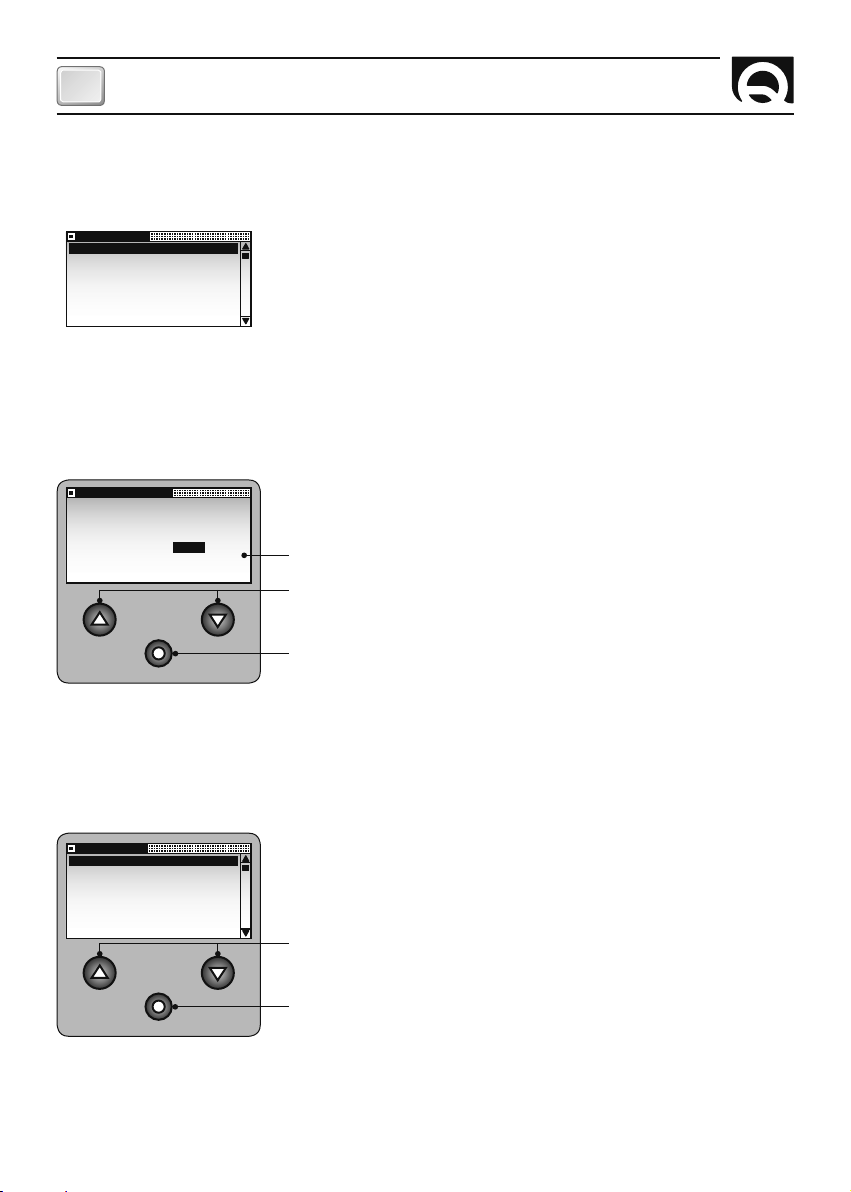
FR
RÉGLAGE DE L'APPAREIL
Si on est en train d'utiliser un appareil SLAVE avec le MASTER connecté sur le réseau, le menu réduit suivant apparaît en forme "réduite":
VALIDATION
DONNEES PERSON
CONTROLES
CONFIG CAN
QUITTER
REMISE A ZERO
ETES-VOUS SURS?
OUI NON
FONCTIONS
ALARME MONTEE
DESCENTE AUTO
QUITTER
Ces sous-menus contiennent les paramètres ou les fonctions particulières pour chaque compteur de chaîne qui ne sont pas connecté au
réseau.
MENU REGLAGES - REMISE A ZERO
Utiliser cette option pour mettre à zéro la longueur de la chaîne devirée.
La fonction peut être validée durant la mise en service ou en cas de
manque de correspondance entre la mesure affichée et la mesure
réelle de la chaîne abaissée. La fenêtre suivante apparaît lorsqu'on
sélectionne les options du menu:
Les options fournies sont: OUI et NON.
Sélectionnent les valeurs disponibles.
Sert à entrer les valeurs sélectionnées et revenir au MENU REGLAGES.
MENU REGLAGES - FONCTIONS
Cette fonction sert à activer ou valider les fonctions relatives aux
messages d'anomalie durant la montée et la descente automatique. Le
sous-menu de l'option FONCTIONS est le suivant:
48
Sélectionnent les options du sous-menu.
Appuyer pour accéder au menu en mode INVERSE. En cas de sortie, on
revient au menu REGLAGES.
CHC1102M GB F - REV005B
Page 49

RÉGLAGE DE L'APPAREIL
FR
MENU REGLAGES - FONCTIONS - ALARME MONTEE
Cette option sert à activer ou désactiver le message d'anomalie pendant la montée. Elle permet d'arrêter
la montée de l'ancre et avertir l'utilisateur quand la longueur de la chaîne abaissée est inférieure à la
valeur établie.
ATTENTION:
Le message d'anomalie durant la montée n'est activé que pendant la montée de
l'ancre et est validé par le compteur de chaîne CHC 1102 M. Il ne fonctionne pas si la montée est
contrôlée par une quelconque commande externe auxiliaire.
ATTENTION: Le compteur de chaîne ne peut pas compenser l'inertie du guindeau (le barbotin peut
tourner dans de le sens la montée après avoir désactivé la commande). Tenir compte de ce facteur
lorsqu'on choisit la valeur limite de la montée.
ATTENTION: Le message d'anomalie n'est affiché que si la mesure est inférieure à la limite
préétablie.
ATTENTION: En cas de message d'anomalie, l'opérateur doit s'assurer que l'ancre monte
correctement.
ALARME MONTEE
ENTRER VALEUR:
DESACTIVE
ALARME MONTEE
ENTRER VALEUR:
1.0 M
CHC1102M GB F - REV005B
Les fenêtres des messages d'anomalie durant la montée sont montrées
ci-dessous:
Réglage usine: DESACTIVE.
Si l'unité de mesure établie est exprimée en METRES, les options possibles
sont DESACTIVE, 1.0M, 1,5M, 2.0M, 2.5M, 3.0M, 3.5M, 4.0M, 4.5M, 5.0M.
Si l'unité de mesure établie est exprimée en PIEDS, les options possibles
sont DESACTIVE, 3.0FT, 4.5F, 6.0F, 7.5FT, 9.0FT, 10.5FT, 12.0FT, 13.5FT, 15FT.
Passer à la valeur supérieure.
Passer à la valeur inférieure.
La valeur est confirmée et on revient au menu FONCTIONS.
49
Page 50

FR
RÉGLAGE DE L'APPAREIL
MENU REGLAGES - FONCTIONS - DESCENTE AUTOMATIQUE
Cette option est utilisée pour contrôler la descente automatique en permettant d'abaisser l'ancre
automatiquement à la profondeur préétablie (voir chapitre Fonctionnement de l'Appareil, DESCENTE
AUTOMATIQUE).
ATTENTION: le compteur de chaîne ne peut pas compenser l'inertie mécanique du guindeau
(le barbotin peut tourner dans le sens de la descente après la désactivation de la commande).
Considérer ce problème lorsqu'on sélectionne la valeur pour la descente automatique.
ATTENTION: même si la descente automatique est activée, l'opérateur doit contrôler la descente
de l'ancre.
DESCENTE AUTO
ENTRER VALEUR:
DESACTIVE
DESCENTE AUTO
ENTRER VALEUR:
5 M
DONNEES PERSON
CONTRASTE
ECLAIRAGE
TEMPS ECLAIRAG
SON DE TOUCHES
TOUCHES BLOQUE
QUITTER
Les fenêtres des messages d'anomalie durant la montée sont montrées
ci-dessous:
Réglage usine DESACTIVE.
Si l'unité de mesure est exprimée en METRES, les options possibles
sont: OFF, de 5M à 100M, avec pas de 5M.
Si l'unité de mesure est exprimée en PIEDS, les options possibles sont:
OFF, de 15FT à 300FT, avec pas de 15FT.
Passer à la valeur supérieure.
Passer à la valeur inférieure.
La valeur est confirmée et on revient au menu FONCTIONS.
MENU REGLAGES
DONNEES PERSONNELLES
Utiliser cette option pour activer ou désactiver diverses fonctions, de
manière à personnaliser l'appareil.
Le sous-menu pour l'option DONNEE PERSON. est le suivant:
Sélectionnent les options du sous-menu.
50
Appuyor sur cette touche pour accéder au menu en mode INVERSE. Si
SORTIE a été sélectionné, on revient au menu REGLAGES.
CHC1102M GB F - REV005B
Page 51

CONTRASTE
ENTRER VALEUR:
ECLAIRAGE
ENTRER VALEUR:
RÉGLAGE DE L'APPAREIL
FR
MENU REGLAGES - DONNEES PERSONNALISEES
CONTRASTE
Cette option sert à régler le contraste de l'écran. Le changement du
contraste se vérifie lorsqu'on entre la valeur, sans la valider.
4
Les valeurs que l'on peut choisir sont: 1, 2, 3, 4, 5, 6, 7, 8
(réglage usine: 4).
Pour passer à la valeur supérieure.
Pour passer à la valeur inférieure.
Pour entrer la valeur et revenir au menu DONNEES PERSON.
MENU REGLAGES - DONNEES PERSONNALISEES
ILLUMINATION
Cette option est utilisée pour régler l'intensité du rétro éclairage de
l'écran. La modification de l'intensité est validée après l'entrée de la
valeur sans la valider,
4
Les valeurs qu'on peut choisir sont: OFF, 1, 2, 3, 4, 5, 6, 7, 8
(réglage usine: 4).
Pour passer à la valeur supérieure.
Pour passer à la valeur inférieure.
Pour entrer la valeur et revenir au menu DONNEES PERSON.
TEMPS ECLAIRAG
ENTRER VALEUR:
30S
CHC1102M GB F - REV005B
MENU REGLAGES - DONNEES PERSONNALISEES
TEMPS EGLAIRAGE
Cette option est utilisée pour établir le temps de retard d'éteindre le
rétro éclairage.
Le laps de temps est calculé à partir du moment où on a relâché la
dernière touche (ou à la fin de la CHUTE LIBRE).
Les valeurs que l'on peut entrer sont: 30S, 60S, 90S, 120S, 180S, 240S,
ACTIVE (toujours éclairé) (réglage usine: 30 S).
Pour passer à la valeur supérieure.
Pour passer à la valeur inférieure.
Sert à entrer la valeur et à revenir au menu DONNEES PERSON.
51
Page 52

FR
RÉGLAGE DE L'APPAREIL
MENU REGLAGES - DONNEES PERSONNALISEES
SON DES TOUCHES
Utiliser cette option pour activer ou désactiver le son lorsque l'on
SON DE TOUCHES
ENTRER VALEUR:
OUI NON
appuie sur les touches.
On peut sélectionner OUI ou NON
(l'option introduite à l'atelier est OUI).
Pour sélectionner les options disponibles.
Sert à entrer la valeur et à revenir au menu DONNEES PERSON.
MENU REGLAGES - DONNEES PERSONNALISEES
TOUCHES BLOQUE
Par l'intermédiaire de cette fonction, on affiche le temps de verrouillage
des touches
TOUCHES BLOQUE
ENTRER VALEUR:
4 min NON
que dès que le temps affiché s'est écoulé depuis qu'il se trouve à l'arrêt.
Les valeurs que l'on peut entrer sont: DESACTIVE, 1min, 2min, 3min,
4min, 5min, 6min, 7 min, 8min, 9min, 10min.
(réglage usine: DESACTIVE)
Sert à augmenter.
Sert à diminuer.
La valeur est confirmée et on revient au menu
DONNEES PERSONNALISEES.
p
et q (UP et DOWN). L'instrument se met en touches blo-
DATE ET HEURE
52
2003 JEN 03
00:00
QUITTER
MENU REGLAGES
DATE ET HEURE
Cette fonction sert à régler la date et l'heure de l'appareil.
La fenêtre pour l'option DATE/HEURE est montrée ci-dessous:
Sert à augmenter.
Sert à diminuer.
Sert à entrer la valeur et à passer au paramètre suivant.
Si on sélectionne QUITTER, on revient au menu REGLAGES.
CHC1102M GB F - REV005B
Page 53
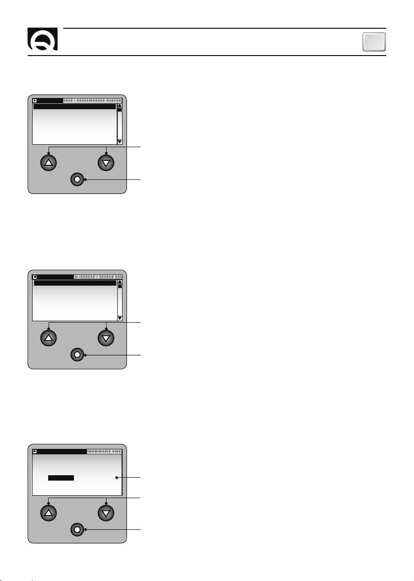
LANGUE
ENGLISH
ITALIANO
FRANCAIS
DEUTSCH
ESPANOL
CALIBRAGE
UNITE DE MESUR
TOUR BARBOTIN
NR D'AIMANTS
CHUTE LIBRE
QUITTER
RÉGLAGE DE L'APPAREIL
FR
MENU REGLAGES
LANGUE
Utiliser cette option pour sélectionner la langue des messages du
système.
Le sous-menu concernant les LANGUES est le suivant:
Sélectionne les options.
Entre les données et revient au menu REGLAGES.
MENU REGLAGES
CALIBRAGE
Cette option sert à étalonner l'appareil selon le type de guindeau
utilisé.
Le sous-menu de l'option CALIBRAGE est décrit ci-dessous:
Sélectionnent les options du sous-menu.
UNITE DE MESUR
ENTRER VALEUR:
METRES PIEDS
CHC1102M GB F - REV005B
Si on frappe sur cette touche on peut accéder au menu affiché en mode
REVERSE. Si on sélectionne QUITTER, on revient au menu REGLAGES.
MENU REGLAGES - CALIBRAGE
UNITE DE MESURE
Cette option sert à sélectionner l'unité de mesure pour la longueur de
la chaîne descendue.
Les unités de mesure utilisées sont: METRES, PIEDS
(réglage usine: METRES).
Sélectionne les options disponibles.
Pour entre les valeurs et revenir au menu CALIBRAGE.
53
Page 54

FR
RÉGLAGE DE L'APPAREIL
MENU REGLAGES - CALIBRAGE - TOUR BARBOTIN
Cette option sert à régler la longueur de la chaîne déroulée chaque fois que le barbotin effectue un tour.
Pour obtenir cette valeur, il faut démonter le barbotin du guindeau et mesurer la longueur de la chaîne
pour faire le tour du barbotin.
Lire le livret d'utilisation
de guindeau pour
démonter et remonter le
TOUR BARBOTIN
barbotin.
La précision de la valeur introduite pour l'option TOUR BARBOTIN peut influencer la
longueur de la chaîne descendue.
TOUR BARBOTIN
ENTRER VALEUR:
10.0 CM
Si l'unité de mesure est exprimée en METRES, les valeurs vont de 0.1 à
999.9 cm (réglage usine: 10 cm).
Augmente la valeur.
Diminue la valeur.
Entre la valeur et permet de revenir au menu CALIBRAGE.
TOUR BARBOTIN
ENTRER VALEUR:
NR D'AIMANTS
ENTRER VALEUR:
54
10.0 INC
1
Si l'unité de mesure est exprimée en PIEDS, les valeurs vont de 0.1 à
999.9 inch (réglage usine: 10 inch).
MENU REGLAGES - CALIBRAGE - NOMBRE D'AIMANTS
Utiliser cette option pour entrer le nombre d'aimants montés sur le
barbotin.
Les valeurs à utiliser vont de 1 à 16 (réglage usine: 1).
Augmente la valeur.
Diminue la valeur.
Entre la valeur et permet de revenir au menu CALIBRAGE.
CHC1102M GB F - REV005B
Page 55

CHUTE LIBRE
ENTRER VALEUR:
0,5 s
RÉGLAGE DE L'APPAREIL
FR
MENU REGLAGES - CALIBRAGE
CHUTE LIBRE AUTO
Grâce à cette gestion, on affiche le temps nécessaire au système de
chute libre automatique du guindeau pour se désactiver.
Les valeurs que l'on peut entrer sont: DESACTIVE, de 0.1s a 7s.
(réglage usine: DESACTIVE)
Augmente la valeur.
Diminue la valeur.
Entre la valeur et permet de revenir au menu CALIBRAGE.
REMONTEECHUTE LIBRE
ALLARM MONTEE
VITESSE 20 M/M
0.1s-7s
ATTENTION: La gestion de la chute libre automatique devra exclusivement être activée avec
un guindeau équipé d'un système automatique de chute libre. Voir le manuel d'instruction du
guindeau utilisé.
ATTENTION: si la gestion de chute libre automatique est activée, le délai de signalisation
"d'absence capteur" variera en fonction de la valeur introduite au paramètre CHUTE LIBRE AUTO
et la fonction de descente automatique sera désactivée; cette dernière se réactivera dès que la
gestion de chute libre sera désactivée.
CHC1102M GB F - REV005B
55
Page 56

FR
RÉGLAGE DE L'APPAREIL
MENU REGLAGES - CALIBRAGE AUTOMATIQUE
Se servir de cette option pour étalonner automatiquement l'appareil. La
fenêtre de l'option CALIBRAGE AUTOMATIQUE est montrée ci-dessous:
CALIBRAGE AUTO
ENTRER VALEUR:
METRES PIEDS
QUITTER
Cette option permet de sélectionner l'unité de mesure pour la longueur
de la chaîne descendue. Les valeurs peuvent être exprimées en METRES
ou PIEDS.
Sélectionne les valeurs disponibles.
Entrer la valeur et passer à l'affichage qui suit pour la procédure
d'ETALONNAGE AUTOMATIQUE. Sélectionner QUITTER pour revenir au
menu REGLAGES.
CALIBRAGE AUTO
APPUYER
JUSQU' A 20 FT
DE PROFONDEUR
APPUYER POUR
QUITTER
Cette fenêtre indique, sans interruptions, qu'il faut descendre 6 mètres
de chaîne (ou 20 pieds, selon l'unité de mesure choisie).
Selon le nombre de tours que le barbotin a effectué (comptés par
CALIBRAGE AUTO
APPUYER
JUSQU' A 6M
DE PROFONDEUR
APPUYER POUR
QUITTER
l'appareil), le compteur calcule la longueur de la chaîne déroulée
pendant chaque tour.
Désactivée
Fait descendre la chaîne et compte le nombre de tours du barbotin.
Annule la procédure et permet de revenir au menu REGLAGES.
Une fois que la touche q (DOWN) a été relâchée, l'appareil arrête la descente de la chaîne et entre les
valeurs suivantes:
CM = 600/nombre des tours comptés
TOUR BARBOTIN
NOMBRE D'AIMANTS =1
INC = 240/nombre des tours comptés
TOUR BARBOTIN
NOMBRE D'AIMANTS =1
La fenêtre suivante sera affichée pour deux secondes:
CALIBRAGE AUTO
FIN DE
PROCEDURE
56
Et on revient au menu REGLAGES.
CHC1102M GB F - REV005B
Page 57

RÉGLAGE DE L'APPAREIL
FR
CONTROLES
TEST CAPTEUR
TEST LCD
BATT HORLOGE
VERSION SW
DONNEES FABRIQ
CONTROLE FLASH
CONTROLES
VERSION SW
DONNEES FABRIQ
CONTROLE FLASH
CONTROL EEPROM
MESSAGE CAN
QUITTER
TEST CAPTEUR
ETAT DU CAPTEUR:
DESACTIVE
TEST CAPTEUR
ETAT DU CAPTEUR:
ACTIVE
MENU REGLAGES
CONTROLES
Grâce à cette option, on peut effectuer les procédures de contrôle pour
vérifier le fonctionnement de l'appareil. Les sous-menus de CONTROLES
sont les suivants:
Sélectionne les options du sous-menu.
Happuier sur la touche pour accéder au menu mis en évidence dans le
mode REVERSE. Si on sélectionne QUITTER, on peut revenir au menu
REGLAGES.
MENU REGLAGES - CONTROLES
TEST CAPTEUR
Cette fonction est utilisée durant la mise en service ou pour vérifier le
bon fonctionnement du capteur de proximité. Si le capteur ne détecte
pas l'aimant, le message ACTIVE apparaît et l'alarme entre en action
sinon le message DESACTIVE apparaît et l'alarme reste éteinte.
Pour revenir au menu CONTROLES.
MENU REGLAGES - CONTROLES - TEST LCD
On utilise cette fonction pour vérifier l'état de l'afficheur LCD.
Une fois que l'option Contrôles a été validée, tous les pixels de l'afficheur sont activés pour 5 secondes.
Ensuite le système revient au menu CONTROLES.
BATT HORLOGE
MENU REGLAGES - CONTROLES
BATTERIE HORLOGE
BATT HORLOGE
X.XX VDC
Cette fonction permet d'afficher la tension de la batterie tampon de
l'horloge.
Pour revenir au menu CONTROLES.
CHC1102M GB F - REV005B
57
Page 58

FR
RÉGLAGE DE L'APPAREIL
MENU REGLAGES - CONTROLES
DONNEES DE FABRICATION
VERSION SW
VERSION SW
VX.XX
Cette fonction permet d'afficher la version du logiciel installé pour
l'appareil:
Pour revenir au menu CONTROLES.
MENU REGLAGES - CONTROLES
DONNEES DE FABRICATION
Cette fonction permet d'afficher divers paramètres de fabrication et
DONNEES FABRIQ
ETES-VOUS SURS?
OUI NON
d'effectuer une REMISE A ZERO de l'appareil. La fenêtre de l'option
DONNEE FABRIQ. est montrée ci-dessous:
On peut utiliser les options OUI ou NON.
Sélectionnent les options du sous-menu.
CONTROLE FLASH
CONTROLE FLASH
REEL: XXXX
SOMME: YYYY
58
Entre l'option choisie.
MENU REGLAGES - CONTROLES
CONTROLE FLASH (MEMOIRE PROGRAMME)
Cette fonction sert à afficher la valeur "checksum" de la mémoire
EEPROM calculée (SOMME) et celle mise en mémoire (REELLE).
Les deux valeurs doivent coïncider pour un bon fonctionnement du
système.
Sert à revenir au menu CONTROLES.
CHC1102M GB F - REV005B
Page 59

CONTROL EEPROM
CONTROL EEPROM
REEL: XXXX
SOMME: YYYY
MESSAGE CAN
TX MSG: 000
RX MSG: 000
LAST ID: 000
CAN UPD: 000
RÉGLAGE DE L'APPAREIL
FR
MENU REGLAGES - CONTROLES
CONTROLE EEPROM (MEMOIRE DES DONNEES)
Cette fonction sert à afficher la valeur "checksum" de la mémoire
EEPROM calculée (SOMME) et celle mise en mémoire (REELLE).
Les deux valeurs doivent coïncider pour un bon fonctionnement du
système.
Sert à revenir au menu CONTROLES.
MENU REGLAGES - CONTROLES
MESSAGES CAN
Cette fonction est utilisée pour afficher certaines informations sur la
transmission des messages CAN.
CONFIG CAN
ENTRER VALEUR:
MASTER SLAVE
CHC1102M GB F - REV005B
Sert à revenir au menu CONTROLES.
MENU REGLAGES
CONFIGURATION CAN
Cet option permet de définir la priorité de l'appareil connecté au réseau
CAN (voir appareil MULTIPLES).
Les options disponibles sont MASTER et SLAVE (réglage usine: MASTER).
Sélectionnent les options disponibles.
Entre l'option souhaitée et sert à revenir au menu CONTROLES.
59
Page 60

FR
ERREURS ET PROBLEMES DE SYSTEME
ERREURS SYSTEME
Pendant l'allumage, appareil peut indiquer la présence de certaines anomalies dans le système.
Erreur checksum
Le système indique une anomalie pendant la mise en mémoire des données et une des fenêtres suivantes
apparairent:
CONTROLE CHECKSUM
FLASH CHECKSUM
ERREUR
REEL: XXXX
SOMME: YYYY
Erreur checksum mémoire EEPROMErreur checksum mémoire FLASH
CONTROLE EEPROM
EEPROM CHECKSUM
ERREUR
REEL: XXXX
SOMME: YYYY
Si un des messages ci-dessus devait apparaître, ne pas utiliser l'appareil et contacter un Centre de Service
Après Vente QUICK
®
.
Erreur Multi-Master
Si l'appareil détecte la présence de plusieurs instruments MASTER sur le
réseau CAN, la fenêtre suivante apparaîtra:
Indiquer la priorité de l'instrument connecté au réseau CAN
(voir chapitre INSTRUMENTS MULTIPLES).
MULTI MASTER
ERREUR
ENTRER VALUE:
MASTER SLAVE
PROBLEMES SYSTEME
Les anomalies du système, affichées sur la ligne d'état, sont divisées en trois catégories:
Problèmes avec remise en service automatique, problèmes avec remise en service automatique et
blocage des touches, problèmes avec remise en service manuelle.
PROBLÈMES AVEC REMISE EN SERVICE AUTOMATIQUE.
Dans ce cas, la remise en service est effectuée automatiquement lorsqu'on élimine les causes qui ont
provoqué les anomalies.
Tension d'alimentation trop basse
Le problème est signalé si la tension arrive au-dessous de 10,5 Vdc pour
une seconde. L'élimination du problème se vérifie quand la tension dépasse
11,0 pour plus d'une seconde.
Vérifier la charge des batteries d'alimentation ou l'installation électrique. La
fenêtre suivante apparaît quand l'anomalie se produit:
Tension de la batterie de l'horloge
L'anomalie est signalée quand la tension de la batterie de l'horloge arrive
au-dessous de 2,80 Vdc. L'appareil contrôle la tension de la batterie
pendant l'allumage toutes les demi-heures. Le problème est résolu si la
tension dépasse ou corresponde à 2,80 Vdc. La batterie de l'horloge doit
être remplacée par le personnel d'un centre de service autorisé.
La fenêtre suivante apparaît quand l'anomalie se produit:
60
TENSION BASSE
VITESSE 0 M / M
BATT HORLOGE
VITESSE 0 M / M
CHC1102M GB F - REV005B
Page 61
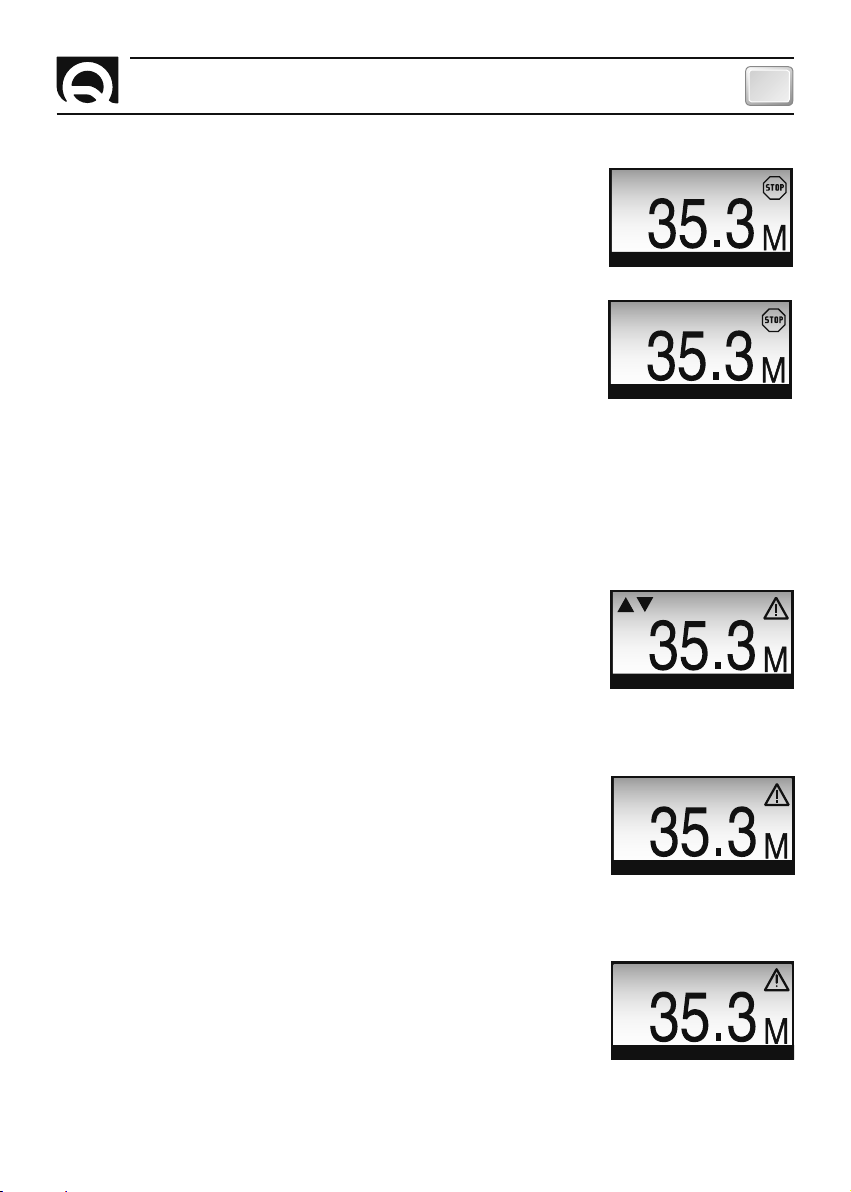
PROBLEMES DE SYSTEME
FR
Manque MASTER
Le problème est signalé si un appareil ayant priorité MASTER n'est pas
MANQUE MASTER
connecté au réseau (voir INSTRUMENTS MULTIPLES). S'assurer que l'appareil
MASTER est allumé ou contrôler le câblage de la ligne des données.
La fenêtre suivante apparaît quand l'anomalie se produit:
Problème de communication avec le CAN BUS
L'anomalie est signalée s'il y a de graves erreurs durant la communication
VITESSE 0 M / M
ERREUR CAN
avec le réseau CAN. S'assurer que le câble des données est bien connecté.
La fenêtre suivante apparaît quand l'anomalie se produit:
VITESSE 0 M / M
PROBLÈMES AVEC REMISE EN SERVICE AUTOMATIQUE ET BLOCAGE DES TOUCHES
L'élimination de ces anomalies intervient automatiquement lorsque le problème qui a produit l'anomalie
disparaît. Dans ce cas-là, certaines touches restent désactivées.
Commandes opposée
Une anomalie est signalée quand les touches UP et DOWN du compteur
de chaîne sont frappées simultanément avec le la touche UP et DOWN de
la commande externe (un autre mesureur ou une commande auxiliaire).
p,q
Si cette anomalie se produit, les touches
(UP, DOWN) restent
OPPOSE
désactivées.
La fenêtre suivante apparaît quand l'anomalie se produit:
VITESSE 0 M / M
Surcharge
Le problème est signalé dans le cas où l'instrument détecte un court-circuit
ou une surcharge à la sortie de l'instrument.
Vérifier le câblage des signaux UP et DOWN et la consommation des
SURCHARGE
utilisateurs reliés à la sortie de l'instrument. Si le problème est présent, les
touches
p,q
(UP, DOWN) sont désactivées.
En présence du problème apparaît une fenêtre similaire à cellle-ci:
VITESSE 0 M / M
Programmation à distance activée
Une anomalie est signalée si un appareil connecté au réseau CAN est en
mode REGLAGES (voir chapitre INSTRUMENTS MULTIPLES).
Attendre que l'appareil n'est plus affiché sur le menu.
Quand l'anomalie se produit, la touche
= (SELECT) reste désactivée.
PROGR A DIST
La fenêtre suivante apparaît quand l'anomalie se produit:
VITESSE 0 M / M
CHC1102M GB F - REV005B
61
Page 62

FR
PROBLEMES DE SYSTEME
ANOMALIES AVEC REMISE EN SERVICE MANUELLE
La résolution de ces problèmes nécessite l'action de l'opérateur: Appuyer sur la touche (SELECT),
p
activation et désactivation de l'appareil. Si ces anomalies se produisent, les touches
restent désactivées.
et q (UP, DOWN)
Montée
Cette anomalie est signalée si la longueur de la chaîne est inférieure à la
valeur introduite dans le menu FONCTIONS/ALARME MONTEE.
La fenêtre suivante apparaît quand l'anomalie se produit:
Capteur de proximité
Cette anomalie est signalée si, en appuyant sur les touches pouq (UP ou
DOWN ), du compteur de chaîne ou d'une commande externe, le capteur
de proximité n'indique pas le déplacement du barbotin dans les 4 secondes
(pour un délai plus long, si la gestion de chute libre automatique est activée).
Contrôler la distance entre l'aimant et le capteur, le fonctionnement du
capteur et le câblage.
La fenêtre suivante apparaît quand l'anomalie se produit:
Court-circuit du capteur de proximité
Cette anomalie est signalée si, en appuyant sur les touches pouq
(UP ou DOWN ) du compteur de chaîne ou d'une commande externe,
l'appareil indique un court-circuit pour une période de temps supérieure a 4
secondes (pour un délai plus long, si la gestion de chute libre automatique
est activée). Contrôler le capteur et le câblage du capteur.
La fenêtre suivante apparaît quand l'anomalie se produit:
ALARME MONTEE
VITESSE 0 M / M
MANQ CAPTEUR
VITESSE 0 M / M
DEF CAPTEUR
VITESSE 0 M / M
MESSAGES DE CONFIRMATION
Les messages de confirmation qui appareissent sur la ligne d'état sont indiqués ci-dessous:
ARRET
Arrêt
La fenêtre suivante apparaît si aucune commande du guindeau n'est pas
utilisé.
VITESSE 0 M / M
Mise en mémoire
Apries 4 secondes depuis la dernière opération (montée, descente, descente
automatique, chute libre), l'appareil met en mémoire (sur l'EEPROM) les
données relatives à la longueur de la chaîne descendue.
Pendant la mise en mémoire, la fenêtre suivante apparaît:
Commandes verrouillées
Dès que le temps affiché au paramètre TOUCHES BLOQUE s'est écoulé,
l'instrument arrêtera la fonctionnalité des boutons p et q(UP et DOWN) et
par conséquent, le fait d'appuyer sur ces boutons ne produira aucun effet.
Pour réactiver la fonctionnalité des touchesp et q(UP et DOWN), il suffit
d'appuyer sur le bouton-poussoir
62
=
(SELECT).
MEMOIRE
VITESSE 0 M / M
BLOQUE
VITESSE 0 M / M
CHC1102M GB F - REV005B
Page 63

ENTRETIEN - CARACTÉRISTIQUES TECHNIQUES
FR
ENTRETIEN
Le compteur de chaîne ne nécessite aucun entretien particulier. Pour garantir un bon fonctionnement,
contrôler les câbles et les connexions électriques toutes les années.
Nettoyer l'écran avec un chiffon moelleux imbibé d'eau. Ne pas utiliser des produits chimiques ou abrasifs
pour nettoyer l'appareil.
CARACTÉRISTIQUES TECHNIQUES
MODELE CHC 1102 M
CARACTÉRISTIQUES DE SORTIE
Charge contacts UP/DOWN 4A max
CARACTÉRISTIQUES D'ENTREE
Tension d'alimentation (1) de 9 à 30 Vdc
Consommation du courant en mode veille (2) 40 mA
Consommation maximale (3) 165 mA + Consommation de la bobine du relais
CARACTÉRISTIQUES AMBIANTES
Température de service (4) -20 ÷ +70 °C
Degré de protection (5) IP 67
CARACTÉRISTIQUES GENERALES
Interface de communication CAN BUS (avec transmetteur différentiel)
Batterie de l'horloge CR2032 (3Vdc)
Classe EMC EN 60945 - FCC Part 15 Rules 47
COFFRET
Poids 750 g
62.2 49.4
Dimensions (L x H x P)
62.2 x 185 x 49.4 mm
(1) L’appareil peut être remis à zéro si la tension d’alimentation est inférieure à 9 Vdc.
(2) La valeur typique avec illumination rétro et torche désactivée et guindeau de l’ancre éteint.
(3) Valeur typique avec illumination rétro activée au niveau max., torche allumé et guindeau activé.
(4) Avec températures inférieures à zéro, les cristaux de l’afficheur LCD ralentissent leur mouvement.
(5) Excepté la zone de connexion des contacts électriques (IP 00).
LA SOCIETÉ QUICK
CHC1102M GB F - REV005B
®
SE RÉ SER VE LE DRO IT D'AP POR TER LES MO DI FI CA TIONS NÉ CES SA I RES A UX CA RAC TÉ RIS TI QUES TE CHNI QUES DE L'AP PA RE IL ET AU CON TE NU DE CE LI VRET SANS A VIS PRÉ A LA BLE.
165
185
59.1 41.6
63
Page 64
CHC 1102 M
CHAIN COUNTER
R005B
GB
Product code and serial number
FR
Code et numéro de série du produit
QUICK® S.p.A. - Via Piangipane, 120/A - 48124 Piangipane (RAVENNA) - ITALY
Tel. +39.0544.415061 - Fax +39.0544.415047
www.quickitaly.com - E-mail: quick@quickitaly.com
 Loading...