

Page 1

High
Quality
Nautical
Equipment
RETRACTABLE THRUSTER
BTR250
Manuale d'uso ELICHE DI MANOVRA RETRATTILI
User's Manual RETRACTABLE THRUSTERS
IT
EN
REV 008
b
Page 2

Page 3

RETRACTABLE THRUSTER BTR250 - IT EN - REV08B
3
Pag. 4 CARATTERISTICHE E INSTALLAZIONE - Requisiti per l’installazione
Pag. 5
INSTALLAZIONE - Posizionamento
Pag. 6
INSTALLAZIONE - Installazione della controflangia
Pag. 7
INSTALLAZIONE - Realizzazione e installazione del portello di chiusura
Pag. 8
INSTALLAZIONE - Installazione del propulsore - Installazione del motore
Pag. 9
INSTALLAZIONE - Verifica e regolazione meccanica del sistema
Pag. 10
INSTALLAZIONE -
Procedura di regolazione
Pag. 11 INSTALLAZIONE -
Regolazione dell’attuatore -
Installazione dei cavetti di fine-corsa delle molle
Pag. 12/13
SCHEMA DI COLLEGAMENTO
Pag. 14
FUNZIONAMENTO
- Dip-Switch selezione opzioni - Selettore rotativo attuatore
Pag. 15
SEGNALAZIONI
Pag. 16
SEGNALAZIONI
Pag. 17 AVVERTENZE IMPORTANTI - FUNZIONAMENTO / USO
Pag. 18/19
MANUTENZIONE
Pag. 20/21
RICAMBI
Pag. 22
CHARACTERISTICS AND INSTALLATION
- Installation requirements
Pag. 23
INSTALLATION
- Positioning
Pag. 24
INSTALLATION
- Counter flange’s installation
Pag. 25
INSTALLATION
- Closing lid’s preparation and installation
Pag. 26
INSTALLATION
- Thruster’s installation - Motor installation
Pag. 27
INSTALLATION
- Mechanical system check and adjustment
Pag. 28
INSTALLATION
- Procedure for the adjustment
Pag. 29
INSTALLATION
- Actuator’s adjustment - Installation of the springs’ limit switch wires
Pag. 30/31
CONNECTION DIAGRAM
Pag. 32
OPERATING
- Option selection Dip-Switch - Actuator current rotary switch
Pag. 33
NOTIFICATION SIGNS
Pag. 34
NOTIFICATION SIGNS
Pag. 35
WARNING - OPERATION/USAGE
Pag. 36/37
MAINTENANCE
Pag. 38/39
SPARE PARTS
INDICE
IT
INDEX
EN
Page 4

4
CARATTERISTICHE E INSTALLAZIONE
IT
RETRACTABLE THRUSTER BTR250 - IT EN - REV08B
MODELLI BTR2512024 BTR2514024 BTR2524024
N° Eliche 2 contro-rotanti
Tunnel Ø 250 mm (9” 27/32)
Potenza Motore 6,5 KW 8,0 KW 10 KW
Tensione 24 V 24 V 24 V
Sezione cavi 120 mm
2
(AWG 4) 120 mm2 (AWG 4) 2 x 95 mm2 (2 x AWG 3/0)
Fusibile 275 A A CNL DIN 275 A A CNL DIN 500 A A CNL DIN
Spinta 120 kgf (264 lb) 140 kgf (308 lb) 240 kgf (529 lb)
Peso 76,3 kg (168,2 lb) 79,2 kg (174,6 lb) 84,2 kg (185,6 lb)
REQUISITI PER L'INSTALLAZIONE
Come già introdotto, nonostante tutti i componenti e gli organi meccanici in movimento siano di elevata qualità, la corretta installazione dell’unità propulsiva retrattile è fondamento irrinunciabile ad un sicuro ed efficace utilizzo dell’imbarcazione oltre che
della stessa unità propulsiva.
Si fà nota che l’installazione di tale unità è un’operazione che richiede esperienza oltre che competenza tecnica. Si raccomanda
di affidare l’installazione a personale competente e di consultare il costruttore o architetti navali per valutare appieno l’entità dei
lavori.
L’elica retrattile Quick
®
ha due movimenti separati.
Il movimento principale, relativo alla parte propulsiva, è di tipo basculante. Le cerniere su cui avviene il movimento sono con
cepite per conferire elevata resistenza all’assieme e sono localizzate sul piano della flangiatura piana che lega la struttura preassemblata al supporto solidale alla carena.
Il movimento secondario è relativo al movimento di chiusura del passascafo da cui esce il tunnel. Questo movimento è di tipo
basculante attorno alla cerniera che è stata progettata e realizzata per effettuare un’apertura del portello priva di interferenze (se
installata come indicazioni).
Motore elettrico, riduttore, leverismi e tutti gli altri componenti sono forniti da Quick
®
già assemblati sulla struttura portante in GRP
e non necessitano regolazioni, adattamenti o sigillature ove non sia indicato in questo manuale.
L’elica retrattile Quick
®
è venduta separatamente dalla controflangia che può essere fornita in diversi materiali per rispondere alla
diversa tipologia di scafi. Quick
®
è in grado di fornire supporti in acciaio inossidabile, lega d’alluminio o GRP, fondamentali per una
installazione veloce, solida e precisa.
Per le carene in vetroresina il supporto deve essere laminato nello scafo rispettando le vigenti norme in materia di giunzioni.
L’unità propulsiva distribuisce sollecitazioni meccaniche allo scafo attraverso la controflangia. La forza della giunzione sarà deter
-
minata da laminazioni sovrapposte, realizzate a “regola d’arte”.
PRIMA DI UTILIZZARE L’ELICA RETRATTILE LEGGERE ATTENTAMENTE IL PRESENTE MANUALE D'USO.
IN CASO DI DUBBI CONSULTARE IL RIVENDITORE QUICK®.
ATTENZIONE: i thruster Quick® sono stati progettati e realizzati per asservire all’uso nautico.
Non utilizzare questi apparecchi per altri tipi di applicazioni.
Quick® non si assume alcuna responsabilità per i danni diretti o indiretti causati da un uso improprio dell’apparecchio o da
una scorretta installazione.
Il thruster non è progettato per mantenere carichi generati in particolari condizioni atmosferiche (burrasca).
Si raccomanda di affidare a un professionista la predisposizione e il posizionamento della controflangia sullo scafo.
Queste istruzioni sono generiche, e non illustrano in alcun modo i dettagli delle operazioni di predisposizione della controflangia
quale competenza del cantiere. In caso di eventuali problemi provocati da un’installazione difettosa del tunnel, ne risponderà in
pieno l’installatore.
Non installare il motore elettrico nelle vicinanze di oggetti facilmente infiammabili.
LA CONFEZIONE CONTIENE: elica di manovra retrattile - guarnizione - cerniera - staffa portello - cavo d’acciaio - manuale di
istruzioni - condizioni di garanzia.
ATTREZZI NECESSARI PER L’INSTALLAZIONE: cacciavite a croce - tronchesi - trapano punta Ø 8,5 mm - chiave esagonale 2,5 / 10 mm
- chiave a forchetta o poligonale 8 / 13 / 17 mm
ACCESSORI QUICK
®
CONSIGLIATI: TCD 1022 - TCD 1042 - TCD 1044 - TSC - TMS - PSS - TFH3 - TFH6.
Quick® si riserva il diritto di apportare modifiche alle caratteristiche tecniche dell'apparecchio e al contenuto di questo manuale senza alcun preavviso.
In caso di discordanze o eventuali errori tra il testo tradotto e quello originario in italiano, fare riferimento al testo italiano o inglese.
F
Page 5

5
INSTALLAZIONE
IT
RETRACTABLE THRUSTER BTR250 - IT EN - REV08B
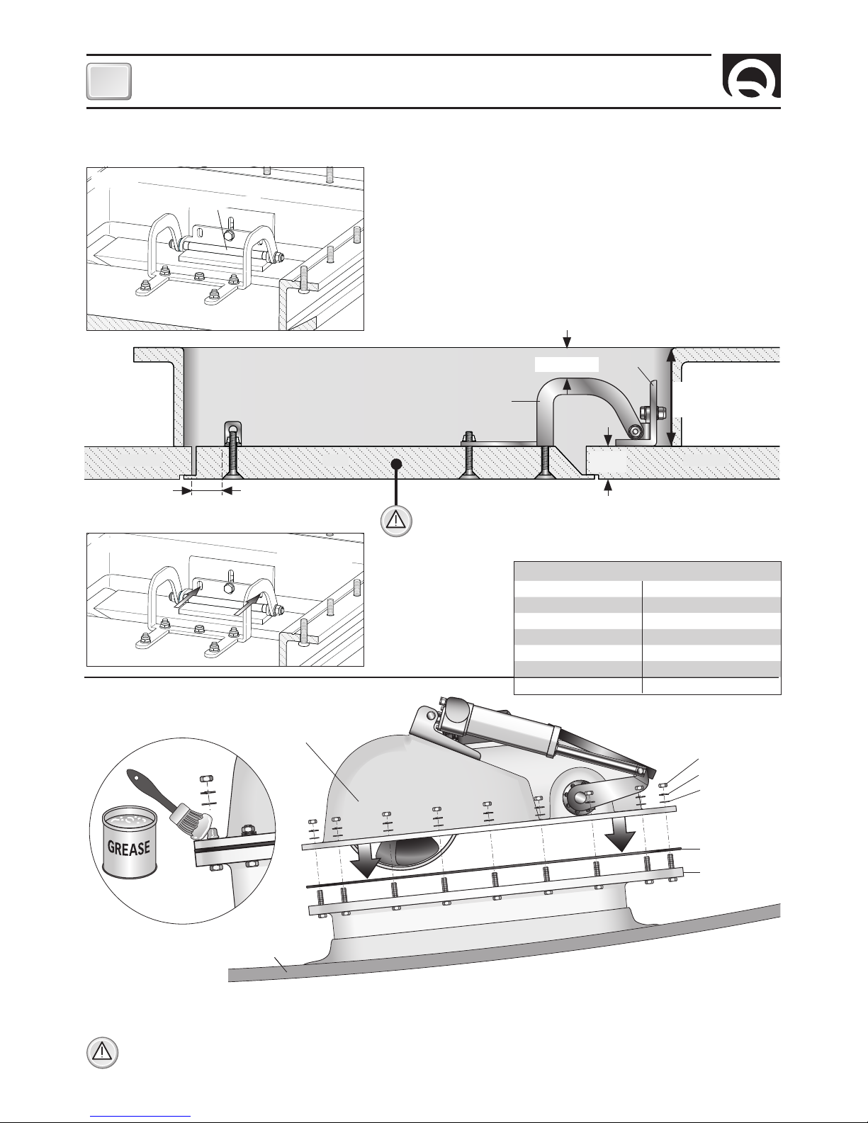
• Per evitare fenomeni di cavitazione nell’elica, si dovrà posizionare il tunnel più a fondo possibile.
minimo 0,75 volte
Ø
tunnel
BARICENTRO
L 2
Posizionamento
INSTALLAZIONE
• Maggiori sono le lunghezze L1 ed L2, maggiore sarà la spinta generata intorno al baricentro.
L 1
Per carene in lega d’alluminio come per carene in acciaio inossidabile, il supporto dovrà essere saldato allo scafo.
Se ben realizzata, l’installazione di una struttura scatolata come quella del supporto può conferire maggior robustezza allo scafo.
Consultare il costruttore, architetti navali e/o ditte specializzate per valutare opere aggiuntive quali traversi e centine in prossimità
della posizione dell’unità propulsiva retrattile.
Page 6

6
IT
RETRACTABLE THRUSTER BTR250 - IT EN - REV08B
INSTALLAZIONE
• Segnare con un pennarello il perimetro
interno della controflangia (fig. 2).
Fig. 2 Fig. 3
• Realizzare l’apertura dello scafo tagliando lungo la linea dell’area di taglio
precedentemente tracciata (fig. 4).
Fig. 4
Fig. 5
• Realizzare, su tutto il perimetro dell’apertura dello scafo, una
solida battuta per la chiusura del portello (fig. 6).
• Rimuovere la controflangia e segnare
l’area di taglio: 480 x 420 mm (fig. 3).
PORTELLO
SCAFO
Fig. 6
CONTROFLANGIA
480 mm 100 mm
420 mm
Installazione della controflangia
Accedere direttamente nella parte interna dello scafo, nella zona in cui il propulsore verrà installato.
Fig. 1
SP
X
X
Y
SCAFO
CONTROFLANGIA
La posizione del propulsore dovrà permettere agevoli manovre di installazione.
F
• Nelle due posizioni (X) dei lati lunghi della controflangia, l’altezza deve essere di 130/140 mm meno lo spessore dello scafo (SP).
Nella parte centrale della controflangia (Y) adattare la sagoma alla curva dello scafo (fig. 1).
• Sagomare i lati corti della controflangia come la curva dello scafo, nella posizione dove si intende fissarla (fig. 1B).
• Appoggiare la controflangia opportunamente tagliata e verificare che i quattro lati aderiscano allo scafo, se così non fosse adat
-
tarla fino a farla appoggiare ed aderire allo scafo nella posizione dove si intende fissarla.
(X = 130/140 mm - SP)
•
Allineare la controflangia all’apertura dello scafo e verificare che
le due altezze (X) siano corrette.
Resinare la controflangia, o saldarla nel caso di alluminio o accia-
io, secondo le tecniche identificate come le più idonee al tipo di
costruzione della carena (fig. 5).
CUT LINE
Fig. 1B
Page 7

7
INSTALLAZIONE
IT
RETRACTABLE THRUSTER BTR250 - IT EN - REV08B
Fig. 7
ATTENZIONE: prestare particolare attenzione ad evitare interferenze tra il coperchio e l’apertura dello scafo.
Contatti troppo precisi provocheranno danni all’intero sistema di movimento.
• Realizzare il portello di chiusura mantenendo un gioco
su tutti i lati dai 3 ai 5 mm (fig. 7), facendo particolare
attenzione al lato cerniera realizzando le pareti interne inclinate a 45° in modo che non interferiscano con
lo scafo in apertura (fig. 8).
• Per ottenere la corretta apertura della cerniera, le superfici dello scafo e del portello devono essere sullo
stesso livello (fig. 9).
45°
5 mm
Realizzazione e installazione del portello di chiusura
PORTELLO SCAFO
CONTROFLANGIA
ANGOLARE
Fig. 8
Fig. 10A
PORTELLO SCAFO
CONTROFLANGIA
ANGOLARE
CERNIERA
36 mm
60 mm
Fig. 10B
A
B1
B2
C1
COLLA
STRUTTURALE
GRP LAYERS
N° 3 VITI M8
Fig. 9
PORTELLO
STAFFA
PORTELLO
SCAFO
CERNIERA
ANGOLARE CONTROFLANGIA
C2
ANGOLARE
ANGOLARE
• Sistemare correttamente l’angolare sullo scafo
(fig. 10A+10B - part. A).
Fissare l’angolare con colla strutturale
(fig. 10B - part. B1-B2).
Scegliere se fissare l’angolare allo scafo con 3 viti M8
o resinandolo (fig. 10B - part. C1-C2).
Page 8
8
IT
RETRACTABLE THRUSTER BTR250 - IT EN - REV08B
INSTALLAZIONE
Fig. 14
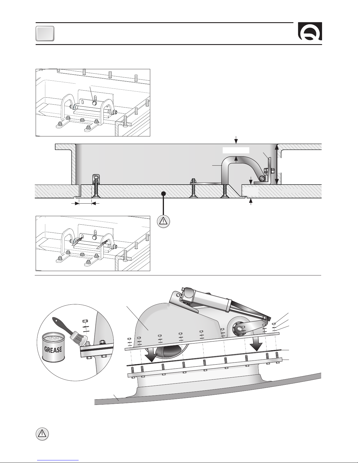
• Posizionare correttamente la guarnizione sulla controflangia, assemblare il propulsore, spalmare grasso marino sul filetto dei
bulloni (già inseriti nella controflangia) e fissare saldamente con le viterie in dotazione (fig.14).
ATTENZIONE: è bene controllare, dopo circa una settimana dall’installazione, il corretto serraggio delle viti, per compen
-
sare eventuali assestamenti della guarnizione.
Installazione del propulsore
GUARNIZIONE
CONTROFLANGIA
RONDELLA
GROWER
DADO
SCAFO
PROPULSORE
Fig. 12
20 mm
PORTELLO
Max
50 mm
CONTROFLANGIA
CERNIERA
ANGOLARE
SCAFOSCAFO
• Fissare in maniera provvisoria il portello nella sua sede.
• Avvitare la cerniera sull’angolare con la sola vite centrale (fig. 11).
• Posizionare la cerniera e la staffa portello nelle posizioni corrette.
Segnare tutti i punti di fissaggio (fig. 12), rimuovere la cerniera e la staffa
portello e forare con punta da Ø 8.5 mm.
Fissare la cerniera e la staffa portello, nelle posizioni realizzate, con vite
-
ria inox adatta all’applicazione.
Regolare la vite centrale della cerniera (fig. 11) e posizionarla corretta-
mente in modo che il portello si apra senza impedimenti.
VITE CENTRALE
Fig. 11
Realizzazione e installazione del portello di chiusura
• Forare l’angolare e fissare saldamente anche le altre due viti M8 (fig. 13).
N° 2 VITI M8
Fig. 13
Min.
90 mm
ATTENZIONE: per permettere un solido fissaggio della cerniera e
della staffa, il portello non deve presentare al suo interno zone vuote, o riempimenti non strutturali (fig. 12).
Min. 5 mm
Page 9

9
INSTALLAZIONE
IT
RETRACTABLE THRUSTER BTR250 - IT EN - REV08B
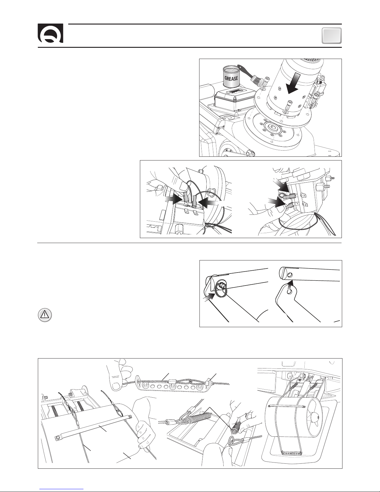
• Fig. 18 - Inserire una estremità del cavo nella staffa portello (part. A). Far passare il cavo sotto alla guida fissata al tunnel (part. B).
Agganciare le estremità del cavo alle due molle (già posizionate sul corpo basculante) (part. C).
Installazione finale del cavo nel portello (part. D).
Fig. 18
A
B
C
D
CAVO
D’ACCIAIO
TUNNEL
MOLLE
STAFFA PORTELLOCAVO D’ACCIAIO
GUIDA CAVO
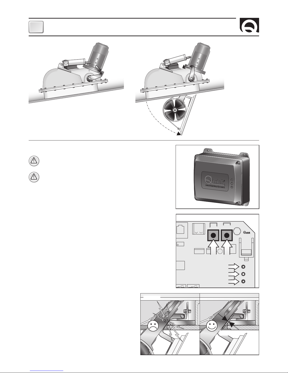
Verifica e regolazione meccanica del sistema
• Il propulsore BTR non deve essere alimentato.
• Sfilare l’anello e rimuovere il perno (fig. 17/ part. A), sganciare
l’attuatore dalla leva (part. B),
assicurarsi che il sistema sia libero
di aprirsi e chiudersi senza impedimenti meccanici.
ATTENZIONE: quando si sgancia manualmente l’attuatore
l’elica col suo peso fuoriesce totalmente, assicurarsi che
nessuno sia nel suo raggio d’azione.
Fig. 17
A
B
Attenersi alla sequenza riportata di seguito per effettuare la
verifica dell’apertura del portello:
Installazione del motore
• Ingrassare l’albero motore e assicurarsi che la chiavetta sia ben
posizionata.
• Inserire il motore e fissarlo con le 4 viti e 4 grower in dotazione
(fig. 15), opportunamente ingrassate.
Fig. 15
• Connettere i faston rispettando le polarità (fig. 16).
CAVO N°7
CAVO N°5
CAVO N°7
CAVO N°6
Fig. 16
Page 10

10
IT
RETRACTABLE THRUSTER BTR250 - IT EN - REV08B
INSTALLAZIONE
Procedura di regolazione
ATTENZIONE: la seguente procedura deve essere eseguita da personale
qualificato.
ATTENZIONE: presenza di parti meccaniche in movimento. Porre particolare attenzione quando si opera sul propulsore BTR se è alimentato.
• Assicurarsi che tutti i collegamenti elettrici siano stati compiuti in maniera
corretta.
• Rimuovere il coperchio dal contenitore della sched RTC R1 (fig.19).
Per eseguire le regolazioni dei fine corsa bisogna entrare in “modalità
manuale”.
• Tenendo premuti entrambi i pulsanti presenti sulla scheda (fig. 20 / part. A)
alimentare la scheda elettronica RTC R1 fino a che il LED POWER (verde) lampeggerà velocemente (fig. 20 / part. B).
Dopodichè rilasciare entrambi i pulsanti.
• A questo punto è possibile comandare elettricamente coi pulsanti UP e DOWN
l’attuatore.
• Premere il pulsante DOWN fino ad una corsa che permetta di riagganciare
l’attuatore alla leva (vedi paragrafo “Verifica e regolazione meccanica del
sistema” fig. 17 A).
CAN2
UP DWN
POWER
LA STATUS
ERROR
Fig. 20
B
A
D
C
Fig. 19
• Assicurarsi che il sistema sia libero di chiudersi e riaprirsi
senza impedimenti meccanici.
RTC R1
PCB RTC R1
• Premendo il pulsante DOWN l’elica si apre fino all’attiva
-
zione del fine corsa e il LED STATUS diventa verde.
Se il fine corsa non è nella posizione giusta (fig. 21) è pos-
sibile regolarlo (vedi paragrafo Regolazione attuatore).
• Premendo il pulsante UP è ora possibile verificare la chiu
sura del portello, raggiunto il finecorsa il LED STATUS diventa rosso, se non è sufficiente, regolare il fine corsa in
chiusura (vedi paragrafo Regolazione attuatore).
Il propulsore esce già tarato dalla fabbrica, non
dovrebbe essere quindi necessario regolarlo in
chiusura.
F
8/10 mm
Fig. 21
Page 11
11
INSTALLAZIONE
IT
RETRACTABLE THRUSTER BTR250 - IT EN - REV08B
0FF
ON
Fig. 23
Fig. 22
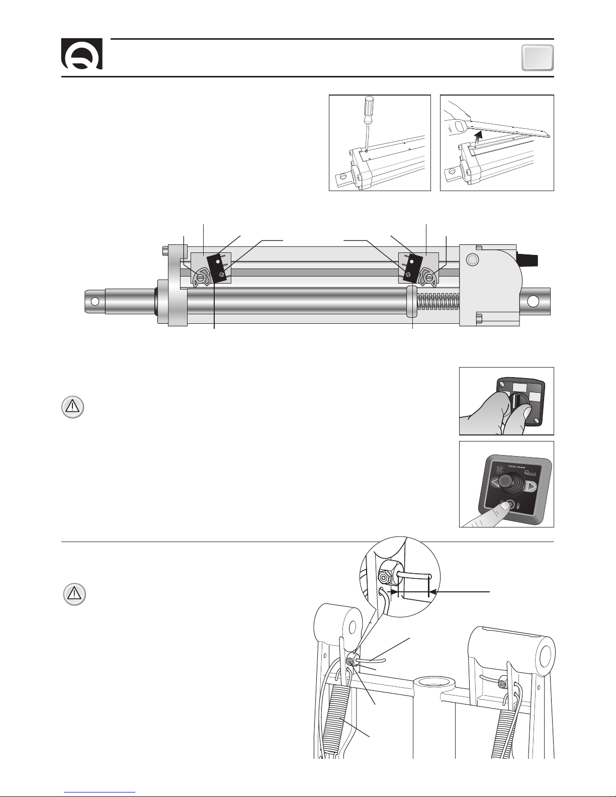
• Per la regolazione dei finecorsa FC1 ed FC2 svitare leggermente la vite di fissaggio e spostarli a
destra o a sinistra a seconda dell’esigenza e riavvitare la vite (fig. 22).
ATTENZIONE: durante ogni regolazione dei finecorsa FC1 ed FC2 verificare che la camma che
li aziona sia sempre posizionata tra di essi e non sia mai in oltrecorsa.
• Interrompere l’alimentazione al propulsore BTR per almeno cinque secondi (fig. 23).
• Alimentare il propulsore BTR (fig. 23).
• Abilitare un comando TCD collegato al propulsore BTR per aprire il propulsore e renderlo operativo
(fig. 24).
• Disabilitare il comando TCD in precedenza abilitato per chiudere il propulsore (fig. 24).
• Accertarsi che la protezione di elevato assorbimento non sia intervenuta (il LED ERROR deve essere
spento - fig. 20 / Part. D).
CAM 1CAM 2
SUPPORTO DI PLASTICA SUPPORTO DI PLASTICA
VITE DI FISSAGGIO
Interno dell’attuatore
Apertura dello sportello laterale dell’attuatore.
SWITCH FC1SWITCH FC2
Regolazione attuatore
REGOLAZIONE DI MASSIMA
CHIUSURA DELL'ELICA
REGOLAZIONE DI MASSIMA
APERTURA DELL'ELICA
Fig. 24
• Aprire completamente il propulsore attivandolo dal comando (fig. 24).
ATTENZIONE: una volta aperto il propulsore, togliere l’alimen
-
tazione (fig. 23) in modo da bloccarlo in questa posizione.
• Inserire i due cavetti di fine corsa nelle apposite sedi.
• Posizionare i due ferma-cavo, mettere in tensione i due
cavetti, verificando che entrambe le molle siano tese alla
stessa lunghezza, stringere i ferma-cavo con una chiave
esagonale da 2,5 mm.
• Bloccare il ferma-cavo stringendo il contro-dado con una
chiave a forchetta da 8 mm, tagliare con tronchesi l’esubero del cavo lasciandone ca. 20/25 mm oltre il ferma-cavo.
• Alimentare il propulsore (fig. 23) che automaticamente effettuerà la chiusura.
• Per accertarsi del corretto funzionamento effettuare alcune
aperture del propulsore attivando il comando (fig. 24).
Installazione dei cavetti di fine corsa delle molle
Fig. 25
Fig. 25
CAVETTO DI FINE CORSA
20/25 mm
FERMA-CAVO
CONTRO-DADO
MOLLA
Page 12
12
IT
RETRACTABLE THRUSTER BTR250 - IT EN - REV08B
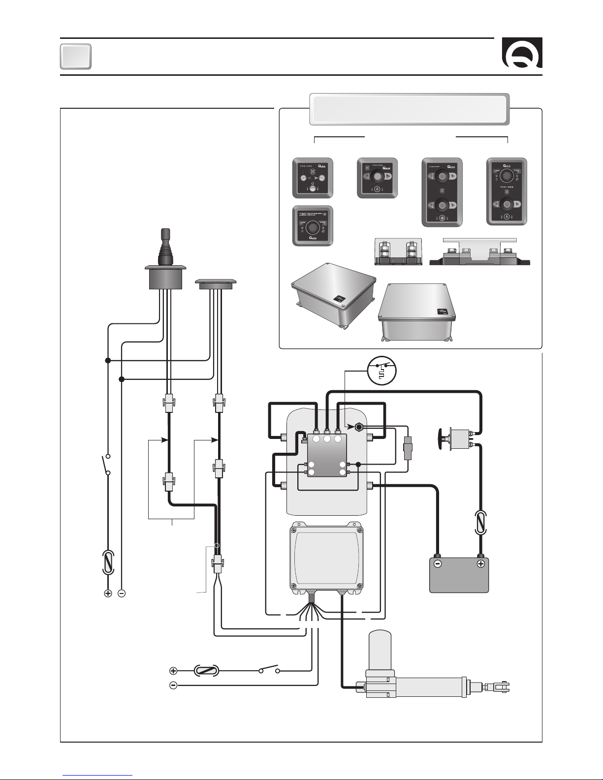
SCHEMA DI COLLEGAMENTO
M1
A A
S S
SX
+
-
DX
-
M2
SISTEMA BASE BTR250
SCHEDA
ELETTRONICA
RTC R1
BATTERIA
12/24V
STACCABATTERIA
NERO
FUSIBILE
RAPIDO 4A
FUSIBILE
VEDI TABELLA
A PAG.4
INTERRUTTORE
ROSSO
NERO
ROSSO
ALLA BATTERIA
SERVIZI
TCD 1042
TCD 1022
SDOPPIATORE
(OPZIONALE)
PROLUNGHE
(OPZIONALI)
*
*
MOTORE
Esempio di collegamento
ALLA BATTERIA
SERVIZI
ATTUATORE
INTERRUTTORE
*
1 2
4
6
5
3
7
FUSIBILE
RAPIDO 10A
PANNELLI DI COMANDO
ACCESSORI QUICK® PER L’AZIONAMENTO
DELL’ELICA DI MANOVRA
STERN
BOW
COMANDO
INTERRUTTURE
DI LINEA TSC
INTERRUTTORE
BATTERIE
PARALLELO- SERIE PSS
PORTAFUSIBILI TFH3 - TFH6
INTERRUTTORE
DI LINEA TMS
TCD 1022 TCD 1042 TCD 1044 TCD 1062
*
NEGATIVO DEI GRUPPI BATTERIA IN COMUNE.
**
ATTENZIONE: IN CASO DI SOVRATEMPERATURA LA PROTEZIONE TERMICA SUL MOTORE SI APRIRÀ E INTERROMPERÀ IL CONTATTO NEGATIVO SUL
TELERUTTORE. ATTENDERE IL TEMPO NECESSARIO ALLA RIATTIVAZIONE.
**
PROTEZIONE
TERMICA
Page 13

13
IT
RETRACTABLE THRUSTER BTR250 - IT EN - REV08B
SCHEMA DI COLLEGAMENTO
M
1
2
3
4
5
6
7
10 A
CN1
CN2
CAN1
CAN2
UP
DWN
CN3
POWER
DL3
DL2
DL1
LA STATUS
ERROR
LA
+
LA
-
LSC COM COM C
-
COMC
-
SXC
-
DXI
-
SXI
-
DXLSO
SCHEDA RTC R1
Selettore rotativo
corrente attuatore
Dip-Switch
selezione opzioni
Fusibile attuatore
Pulsanti movimento manuale
LED verde alimentazione
collegamento CAN bus
LED bicolore stato attuatore
LED rosso segnalazione problemi
ATTUATORE LINEARE
Rosso
Rosso
Nero
Giallo
Verde
Bianco
Negativo gruppo teleinvertitore
Al teleruttore SX
Al teleruttore DX
Connettore femmina TCD contatto 2
Connettore femmina TCD contatto 1
Negativo Alimentazione
Positivo Alimentazione
Page 14

14
IT
RETRACTABLE THRUSTER BTR250 - IT EN - REV08B
Dip-Switch selezione opzioni
SWITCH FUNZIONE DESCRIZIONE
1
Riservata (mantenere sempre off)
ON
1 2 3 4
2
Indica alla stazione di comando CAN che il propulsore è di prua (OFF)
ON
1 2 3 4
Indica alla stazione di comando CAN che il propulsore è di poppa (ON)
ON
1 2 3 4
3
Riservata (mantenere sempre off)
ON
1 2 3 4
4
Riservata (mantenere sempre off)
ON
1 2 3 4
IMPOSTAZIONE DI FABBRICA: 1 = OFF , 2 = OFF , 3 = OFF , 4 = OFF
Selettore rotativo corrente attuatore
I dieci passi selezionabili (da 0 a 9) permettono di impostare una percentuale (vedi tabella) riferita alla corrente/carico massimo
permesso per l’attuatore in uso.
POSIZIONE SELETTORE
ROTATIVO
% CORRENTE/CARICO MASSIMO
0
28%
1
36%
2
44%
3
52%
4
60%
5
68%
6
76%
7
84%
8
92%
9
100%
FUNZIONAMENTO
Qualora sia richiesta una impostazione diversa da quella di fabbrica effettuare le seguenti operazioni:
1) Con la scheda non alimentata posizionare la freccia del selettore rotativo nella posizione voluta.
2) Alimentando la scheda, verrà automaticamente settata la percentuale corrispondente alla posizione selezionata.
Se il limite di corrente/carico massimo è troppo basso rispetto alle reali esigenze di utilizzo potrebbero intervenire le protezioni
contro l’elevato assorbimento dell’attuatore in chiusura e apertura della retrattile con lampeggio di errore 1 e 7.
Page 15

15
IT
RETRACTABLE THRUSTER BTR250 - IT EN - REV08B
SEGNALAZIONI
LED LA STATUS (bicolore)
LED POWER (verde)
STATO LED DESCRIZIONE
SPENTO
Scheda non alimentata
LAMPEGGIO BREVE
Scheda alimentata ma comando non abilitato
LAMPEGGIO VELOCE
Scheda alimentata e modalità movimento attuatore manuale attiva
ACCESO CON BREVE SPEGNIMENTO
Scheda alimentata ma comando non abilitato e link attivo con la stazione di comando CAN
ACCESO
Scheda alimentata e comando abilitato (TCD o stazione CAN).
COLORE LED STATO LED DESCRIZIONE
- SPENTO
Con scheda alimentata, modalità movimento attuatore manuale attiva e anomalia fine corsa presente
ROSSO ACCESO
Retrattile chiusa (fine corsa LSC attivo)
VERDE ACCESO
Retrattile aperta (fine corsa LSO attivo)
ARANCIO ACCESO
Retrattile ne aperta ne chiusa (fine corsa LSC e LSO non attivi)
ARANCIO LAMPEGGIANTE
Retrattile ne aperta ne chiusa (fine corsa LSC e LSO non attivi) ed attuatore lineare in movimento.
SEGNALAZIONI
Di seguito si riporta il significato delle segnalazioni luminose fornite dalla scheda RTC R1 (vedi scheda elettronica a pag.13).
Al temine della sequenza ciclica di lampeggio il LED ERROR rimane spento per un breve periodo.
LED ERROR (rosso)
NUMERO
LAMPEGGI
DESCRIZIONE
NESSUNO Nessuna anomalia presente.
1
Elevato assorbimento attuatore in salita (chiusura retrattile).
La segnalazione avviene dopo che il sistema ha effettuato, in presenza di un attrito meccanico superiore alla soglia impostata,
tre tentativi di risalita. Il problema può essere causato da un corpo estraneo entrato nel meccanismo, dall’imbarcazione in
navigazione a velocità sostenuta, o da problemi meccanici della retrattile e relativo portello.
2
Fusibile aperto.
Si è verificato un assorbimento di corrente superiore a 10A. Il problema si può presentare in presenza di un cortocircuito o
di un sovraccarico sulla linea elettrica dell’attuatore. Verificare il cablaggio delle linee elettriche dalla scheda all’attuatore o
l’assorbimento dell’attuatore stesso.
3
Condizione anomala finecorsa.
Il problema è segnalato nel caso in cui la scheda rilevi una anomalia sui fine corsa (entrambi attivati). Verificare il cablaggio
della linea elettrica dalla scheda ai fine corsa e la loro funzionalità.
4
Interruzione linea comando attuatore.
Il problema è segnalato nel caso in cui la scheda rilevi una interruzione della linea elettrica di comando dell’attuatore. Verifi
-
care il cablaggio delle linee elettriche della scheda all’attuatore.
5
Intervento timeout movimentazione attuatore.
Il problema è segnalato nel caso in cui, la movimentazione impartita all’attuatore non è eseguita, entro un periodo di 15 secondi.
6
Errata configurazione dip-switch.
Il problema è segnalato nel caso in cui le posizioni del dip-switch non siano settate correttamente.
7
Elevato assorbimento attuatore in discesa (apertura retrattile).
La segnalazione avviene dopo che il sistema ha effettuato, in presenza di un attrito meccanico superiore alla soglia impostata,
tre tentativi di discesa. Il problema può essere causato da un corpo estraneo entrato nel meccanismo, dall’imbarcazione in
navigazione a velocità sostenuta, o da problemi meccanici della retrattile e del relativo portello.
8
Elevato assorbimento uscita comando teleinvertitore motore.
Il problema è segnalato nel caso in cui la scheda rilevi un cortocircuito o un sovraccarico sulla linea elettrica di comando del
propulsore.
Verificare il cablaggio delle linee elettriche della scheda al propulsore e l’assorbimento del gruppo teleinvertitore motore
installato sul propulsore.
9
Intervento della protezione termica sul motore.
Il problema è segnalato nel caso in cui sia intervenuta la protezione termica del motore.
Attendere il raffreddamento del propulsore.
Interruzione collegamento uscita comando teleinvertitore motore.
Il problema è segnalato nel caso in cui la scheda rilevi una interruzione della linea elettrica di comando al propulsore.
Verificare il cablaggio delle linee elettriche della scheda al gruppo tele invertitore motore installato sul propulsore.
Page 16

16
IT
RETRACTABLE THRUSTER BTR250 - IT EN - REV08B
AVVERTENZE - FUNZIONAMENTO/USO
FUNZIONAMENTO / USO DELL’ELICA RETRATTILE
Per il corretto uso della retrattile riferirsi al manuale del comando TCD
Accensione
All’accensione la scheda RTC R1 verifica la posizione in cui si trova la retrattile (alzata, abbassata o in posizione intermedia).
Nel caso in cui sia alzata, il sistema non compie azioni.
Nel caso in cui sia abbassata o in posizione intermedia, comanderà la risalita della retrattile.
Comando abilitazione da TCD (Discesa elica retrattile)
Quando la scheda RTC R1 riceve l’abilitazione da un comando TCD, inizia la procedura di discesa della retrattile.
Fino a quando questa procedura non è stata completata i comandi destra/sinistra provenienti dal TCD saranno inibiti.
Durante la fase di discesa la scheda RTC R1 misura la corrente assorbita dall’attuatore lineare.
Se a causa di un attrito meccanico vi è un elevato assorbimento dell’attuatore lineare, la discesa verrà invertita per un breve
periodo per poi riprendere. Dopo 3 tentativi, la scheda RTC R1 segnalerà il problema.
Comando disabilitazione da TCD (Salita elica retrattile)
Quando la scheda RTC R1 riceve la disabilitazione da un comando TCD, inizia la procedura di salita della retrattile.
In risalita i comandi destra/sinistra provenienti dal TCD saranno inibiti.
Durante la fase di salita la scheda RTC R1 misura la corrente assorbita dall’attuatore lineare.
Se a causa di un attrito meccanico vi è un elevato assorbimento dell’attuatore lineare, la salita verrà invertita per un breve periodo per poi riprendere. Dopo 3 tentativi, la scheda RTC R1 segnalerà il problema.
Salita automatica in caso di time out TCD
Con elica abbassata, dopo 6 minuti dall’ultimo comando DX o SX del TCD, l’elica retrattile esegue la procedura di salita.
Rilevamento errori dal TCD
Nel caso il TCD mandi in rete un segnale di errore (comando prolungato, interruzione linea, corto circuito in uscita DX o SX), l’elica retrattile esegue la procedura di salita.
AVVERTENZE IMPORTANTI
ATTENZIONE: questo bow thruster non è realizzato per un funzionamento continuo.
E’ provvisto di protezioni che ne limitano il funzionamento fino ad un tempo massimo, come riportato sul manuale dei
comandi. E’ assolutamente vietato bypassare, o modificare tali protezioni per aumentare il tempo di funzionamento, pena
la decadenza della garanzia e di qualsiasi responsabilità da parte di Quick SPA.
ATTENZIONE: accertarsi che non vi siano bagnanti ed oggetti galleggianti nelle vicinanze, prima di avviare l’elica retrat
-
tile.
ATTENZIONE: si raccomanda, per non danneggiare il sistema, di non navigare con l’elica retrattile aperta; di effettuare
l’apertura e la chiusura dell’elica entro una velocità massima di 4 nodi, in relazione alle correnti e ad una velocità massi
-
ma di 2 nodi, sempre in relazione alle correnti, se si procede a marcia indietro.
ATTENZIONE: si raccomanda, per non danneggiare il sistema, di non abilitare l’elica a velocità superiori a quattro nodi.
ATTENZIONE: non deve essere presente materiale infiammabile nel gavone o nella zona in cui sia presente il motore del
Bow Thruster.
ATTENZIONE: durante l’ormeggio, si raccomanda di non lasciare cime libere in acqua che potrebbero essere risucchiate
dalle eliche causandone la rottura (fig. 26).
Fig. 26
Page 17

17
IT
RETRACTABLE THRUSTER BTR250 - IT EN - REV08B
IN CASO DI EMERGENZA L’ELICA PUÒ ESSERE CHIUSA MANUALMENTE
ATTENZIONE: Interrompere l’alimentazione del propulsore.
Sull’attuatore, sotto il coperchio in plastica, è presente una vite a taglio; ruotarla in senso orario per chiudere il sistema.
PROBLEMI DI CHIUSURA ELICA
ATTUATORE
COPERCHIO IN PLASTICA
VITE A TAGLIO
Page 18

18
IT
RETRACTABLE THRUSTER BTR250 - IT EN - REV08B
MANUTENZIONE
75
7
8
14
13
13
12
12
11
11
10
26
18
17
15
16
27
17
28
18
22
25
17
23
48
49
66
65
49
63
59
51
32
47
46
45
38
41
41
40
40
42
43
39
67 69
74
68
72
70
73
71
44
24
50
54
53
52
51
55
56
57
74
49
44
48
61
62
60
62
29
30
31
32
33
34
35
36
37
64
65
49
66
10
58
9
6
6
5
1
2
3
87
4
21
20
19
82
83
84
81
28
28
17
17
78
79
80
85
86
76
43
77
BTR 2512024
BTR 2514024
BTR 2524024
88
Page 19

19
IT
RETRACTABLE THRUSTER BTR250 - IT EN - REV08B
MANUTENZIONE
I Thruster Quick® sono costituiti da materiale resistenti all’ambiente marino: è indispensabile, in ogni
caso, rimuovere periodicamente i depositi di sale
che si formano sulle superfici esterne per evitare
corrosioni e di conseguenza inefficienza del sistema.
ATTENZIONE: accertarsi che non sia presen
te l’alimentazione al motore elettrico quando
si eseguono le operazioni di manutenzione.
Smontare una volta all’anno, seguendo i seguenti
punti:
• Pulire eliche (63 e 64), tunnel (59) e piede ridutto
-
re (61).
• Sostituire gli anodi di zinco (effettuare più fre
-
quentemente se necessario).
• Sostituire le eliche se danneggiate o usurate.
• Controllare il serraggio di tutte le viti.
• Accertarsi che non vi siano infiltrazioni di acqua
all’interno.
• Verificare che tutte le connessioni elettriche siano
ben fissate e prive di ossido.
• Verificare che le batterie siano in buone condizio
-
ni.
ATTENZIONE: non verniciare gli anodi di
zinco (40 e 65), le sigillature e gli alberi del
piede riduttore dove alloggiano le eliche.
N°
DENOMINAZIONE
1
Vite
2
Grower
3
Motore
4
Cassetta teleinvertitori
5
Carter cassetta
teleinvertitore
6
Fissaggio carter
cassetta teleinvertitori
7 Vite
8 Flangia
9 Chassis
10 O-ring
11 Paraolio
12 Anello
13 Vite
14 Perno
15 Leva attuatore
16 Perno
17 Rondella
18 Anello a molla
19 Contenitore
RX RRC
20 Passacavo
21 Vite
22 Rondella
23 Fulcro
24 Perno
25 Vite
26 Attuatore
27 Piastra attuatore
28 Dado
29 Paraolio
30 Anello elastico interno
31 Albero
32 Chiavetta
33 Cuscinetto
34 Anello elastico esterno
35 Supporto albero
36 Paraolio
37 Giunto omocinetico
38 Corpo basculante
39 Molla
40 Anodo
41 Vite
42 Vite
43 Grower
44 Paraolio
45 Inserto chiavetta
46 Grower
47 Vite
48 Rondella
49 Dado
50 O-ring
51 Cuscinetto
52 Anello elastico interno
53 Anello elastico esterno
54 Paraolio
55 Ferma cavo
56 Vite
57 Dado
58 Albero
59 Tunnel
60 Guarnizione
61 Riduttore
62 Chiavetta
63 Elica 250 L
64 Elica 250 R
65 Anodo
66 Vite
67 Rondella
68 Dado
69 Rondella
70 Vite
71 Dado
72 Vite
73 Guida fune
74 Dado
75 Guarnizione
76 Rondella
77 Vite
78 Albero cerniera
79 Staffa cerniera
80 Rondella
81 Braccio cerniera
82 Staffa portello
83 Vite
84 Angolare
85 Rondella
86 Dado autobloccante
87 Chiavetta motore
88 Cavo
Page 20

20
IT
RETRACTABLE THRUSTER BTR250 - IT EN - REV08B
RICAMBI
1
6
4
2 3
5
7
8
Page 21

21
IT
RETRACTABLE THRUSTER BTR250 - IT EN - REV08B
RICAMBI
N°. DESCRIZIONE CODICE
1A OSP MOTOR 10KW 24V BTR250+T FVEMFEL1K24B25T
1B OSP MOTOR 6500W 24V BTR250+T FVEMFEL6524B25T
1C OSP MOTOR 8000W 24V BTR250+T FVEMFEL8024B25T
2A OSP KIT CASSETTA TELEINV 350A 12V FVSGRCT35012A00
2B OSP KIT CASSETTA TELEINV 350A 24V FVSGRCT35024A00
3 OSP KIT CARTER ‘B’ PER ELICA FVSGCARTABTQB00
4 OSP KIT PROTEZIONE TERMICA BTR FVKPS120BTR0A00
5 OSP KIT ANODI ELICA BTR250 FVSGANBTR250A00
6 OSP KIT RIDUTTORE BTR250 FVSGGBBTR250A00
7 OSP KIT ELICA D250 R FVSGEL250R00A00
8 OSP KIT ELICA D250 L FVSGEL250L00A00
9 OSP ANGOLARE FISS VERT CERN BTR250 FVSLPVNG2500A00
10 OSP KIT CERNIERA+STAFFA PORT BTR250 FVSGCN250000A00
11 OSP KIT FUNE INOX BTR250 COMPLETA FVSFBTR25000A00
9
10 11
Page 22
22
CHARACTERISTICS AND INSTALLATION
EN
RETRACTABLE THRUSTER BTR250 - IT EN - REV08B
BEFORE USING THE RETRACTABLE THRUSTER, CAREFULLY READ THIS USER MANUAL.
IF IN DOUBT, CONTACT YOUR NEAREST QUICK® DEALER.
WARNING: the thruster Quick® have been designed and manufactured for nautical use.
Do not use these appliances for other uses.
Quick® shall accept no responsibility for direct or indirect damages caused by improper use of the appliance or an improper
installation.
The thruster is not designed for maintaining loads generated in particular atmospheric conditions (storms).
It is strongly recommended to entrust a professional with the positioning and presetting of the counter flange on the hull.
These instructions are generic, and do not show by any means the details of the operations of presetting the counter flange,
which falls under the competence of the shipyard. In case of problems caused by a defective installation of the tunnel, the in
-
staller will be held responsible.
Do not install the electric motor near easily inflammable objects.
THE PACKAGE CONTAINS: retractable thruster - gasket - Hinge - Lid bracket - steel cable - user's manual - conditions of warranty.
TOOLS REQUIRED FOR INSTALLATION: Phillips screwdriver - cutting nipper - drill and drill bits Ø 8,5 mm - hexagonal wrenches 2,5 mm
- fork or polygonal key 8 / 13 / 17 mm
QUICK®”ACCESSORIES RECOMMENDED: TCD 1022 - TCD 1042 - TCD 1044 - TSC - TMS - PSS - TFH3 - TFH6.
INSTALLATION REQUISITES
As said, despite all components and moving mechanical parts are of high quality, the correct installation of the retractable propulsion unit is fundamental for a safe and efficient use of the boat, as well as of the same propulsion unit.
Please note that the installation of such unit is an operation requiring experience as well as technical competence. It is recommended to entrust the installation to competent staff and to consult the manufacturer or naval architects to fully evaluate the
entity of the work.
The Quick retractable thruster
®
has two individual movements.
The main movement, relating to the propulsion part, is of tilting type. The hinges on which the movement happens are conceived
to confer high resistance to the set and are located on the flat flange surface that joins the pre-assembled structure to the hull
solid support.
The secondary movement relates to the closing of the through-hull fitting from where the tunnel exits. This movement of the
tilting type takes place around the hinge, which has been designed and manufactured in order to open the lid without interferences
(if properly installed, as per instructions provided).
Electric motor, gear, levers and all other components are supplied by Quick
®
, already assembled on the supporting structure in GRP
and do not require adjustments, adaptations or sealing, unless indicated in this manual.
The Quick retractable thruster® is sold separately from the counter flange, that can be supplied in different materials to comply
with the different types of hulls. Quick® is able to supply stainless steel, aluminium alloy or GRP supports, fundamental for quick,
solid and precise installation.
For the fibreglass hulls the support must be laminate in the hull respecting the current Standards relating to joints. The propulsion unit distributes mechanical stresses to the hull through the counter flange. The force of the joint will be determined by
overlapped, up to standard, laminates.
Quick® reserves the right to introduce changes to the equipment and the contents of this manual without prior notice.
In case of discordance or errors in translation between the translated version and the original text in the Italian language, reference will be made to the Italian or English text.
F
MODELS BTR2512024 BTR2514024 BTR2524024
Nr. Propellers 2 counter rotating
Tunnel Ø 250 mm (9” 27/32)
Motor Power 6,5 KW 8,0 KW 10 KW
Voltage 24 V 24 V 24 V
Section of wire 120 mm
2
(AWG 4) 120 mm2 (AWG 4) 2 x 95 mm2 (2 x AWG 3/0)
Fuse 275 A A CNL DIN 275 A A CNL DIN 500 A A CNL DIN
Thrust 120 kgf (264 lb) 140 kgf (308 lb) 240 kgf (529 lb)
Weight 76,3 kg (168,2 lb) 79,2 kg (174,6 lb) 84,2 kg (185,6 lb)
Page 23

23
INSTALLATION
EN
RETRACTABLE THRUSTER BTR250 - IT EN - REV08B
• To avoid cavitation in the propeller, the tunnel must be positioned as low as possible.
minimum 0,75
times
Ø
tunnel
BARYCENTRE
L 2
• The longer L1 and L2 lengths will be, the greater will be the thrust generated around the center of gravity.
L 1
For aluminium alloy hulls, like for stainless steel hulls, the support must be welded to the hull.
If correct, the installation of a boxed structure like that of the support, can give greater sturdiness to the hull. Consult the manufacturer, naval architects and/or specialised companies to evaluate additional work which beams and ribs near the retractable
propulsion unit.
Positioning
INSTALLATION
Page 24

24
EN
RETRACTABLE THRUSTER BTR250 - IT EN - REV08B
SP
X
X
Y
INSTALLATION
• Mark with a felt-tip pen the internal
perimeter of the counter flange (fig. 2).
480 mm 100 mm
420 mm
Fig. 2 Fig. 3
• Cut the hull along the cutting area pre-
viously marked (fig. 4).
• Align the counter flange to the hull’s opening and check that
the two heights (X) are correct. Resinate the counter flange, or
solder it in case of aluminium or steel, according to the tech
-
niques the most suitable to the hull’s material (fig. 5).
Fig. 4
Fig. 5
• Make a solid coaming for the closing lid on the whole perimeter
of the hull’s opening (fig. 6).
•
Remove the counter flange and mark the
cutting area: 480 x 420 mm (fig. 3).
LID
HULL
Fig. 6
COUNTER FLANGE
Counter flange’s installation
Directly access inside the hull, where the thruster will be installed.
Fig. 1
HULL
COUNTER FLANGE
The thruster position must enable easy maintenance operations.
F
• In the two positions (X) of the long sides of the counter flange, the height must be 130/140 mm less the hull’s thickness (SP) (Fig. 1).
Adapt the shape of the central part of the counter flange (Y) to the hull’s curve.
• Shape the short sides of the counter flange like the hull’s curve, in the position where it’s meant to be fixed (fig. 1B).
• Lay the properly-cut counter flange and check that the four sides fit the hull, or adjust them until they do fit in the position where
the counter flange is meant to be fixed.
(X = 130/140 mm - SP)
CUT LINE
Fig. 1B
Page 25

25
INSTALLATION
EN
RETRACTABLE THRUSTER BTR250 - IT EN - REV08B
Fig. 7
WARNING: pay particular attention to avoid interferences between the lid and the hull opening. Too precise contacts will
cause damages to the entire moving system.
• Make the closing lid by keeping on all sides a space
varying from 3 to 5 mm (fig. 7), paying special attention to the hinge’s side, ensuring that the internal
walls are inclined by 45° so that they don’t hinder the
hull’s opening (fig. 8).
• To obtain the correct opening of the hinge, the sur-
faces of hull and lid must be on the same level (fig. 9).
45°
5 mm
Closing lid’s preparation and installation
LID HULL
COUNTER FLANGE
ANGLE BAR
Fig. 8
Fig. 10A
LID HULL
COUNTER FLANGE
ANGLE BAR
HINGE
36 mm
60 mm
Fig. 10B
A
B1
B2
C1
STRUCTURAL
ADHESIVE
GRP LAYERS
3 SCREWS M8
Fig. 9
LID
LID’S
BRACKET
HULL
HINGE
ANGLE BAR COUNTER FLANGE
C2
ANGLE BAR
ANGLE BAR
• Position the angle bar correctly on the hull
(fig. 10A+10B - part. A).
Fasten the angle bar with structural adhesive
(fig. 10B - part. B1-B2).
Decide whether to fasten the lid bracket to the hull
with 3 M8 screws or with resin (fig. 10B - part. C1-C2).
Page 26
26
EN
RETRACTABLE THRUSTER BTR250 - IT EN - REV08B
INSTALLATION
• Position the gasket on the counter flange, assemble the thruster, spread marine grease on the thread of the bolts (already
screwed in the counter flange) and fasten securely with supplied screws (fig.14).
WARNING: about one week after installation, you should check that all screws are properly tightened in order to compensate for any potential gasket settling.
Fig. 12
20 mm
LID
Max
50 mm
COUNTER FLANGE
HINGE
ANGLE BAR
HULLHULL
• Temporarily fasten the hinge bracket in its housing.
• Screw the hinge onto the angle bar with the central screw only (fig. 11).
• Position the hinge and hinge bracket correctly in the correct positions.
Mark all the fastening points (fig. 12), remove the hinge and hinge bracket
and drill using the Ø 8.5 mm bit.
Fasten the hinge and hinge bracket in the positions marked with stainless
steel hardware suitable for the application.
Adjust the central screw of the hinge (fig. 11) and position it correctly so
that the hatch opens without any hindrance.
CENTRAL SCREW
Fig. 11
Closing lid’s preparation and installation
Min.
90 mm
Fig. 14
Thruster’s installation
GASKET
COUNTER FLANGE
WASHER
GROWER
BOLT
HULL
THRUSTER
• Drill the angle bar
and fasten securely
with the other two
M8 screws (fig. 13).
N 2 SCREWS M8
Fig. 13
CONVERSION FROM DECIMAL TO FRACTIONAL INCHES
3 mm = 1/8” in 50 mm = 1” 31/32 in
5 mm = 3/16” in 100 mm = 3” 15/16 in
8 mm = 5/16” in 130 mm = 5” 1/8 in
8,5 mm = 21/64” in 140 mm = 5” 33/64 in
10 mm = 25/64” in 420 mm = 16” 17/32 in
20 mm = 25/32” in 480 mm = 18” 29/32 in
25 mm = 1” in
WARNING: in order to allow a stable fixing of hinge and bracket,
the lid must present neither empty areas nor non-structural fillings
inside (fig. 12).
Min. 5 mm
Page 27
27
INSTALLATION
EN
RETRACTABLE THRUSTER BTR250 - IT EN - REV08B
System check and mechanic adjustment
• The BTR propeller should be disconnected from power.
• Take the ring off and remove the pin (fig. 17 / part. A), unhook the
actuator from the lever (part B), ensuring that the system is free
to open and close without any mechanical hindrance.
WARNING: when the actuator is manually unhooked, the
thruster completely comes out due to its weight, therefore
ensure that nobody stands in its range of action.
Fig. 17
A
B
Follow the sequence described below to verify the opening
of the hatch:
Motor installation
• Grease the drive shaft and ensure that the key is well positioned.
• Insert the motor and fix it by means of the 4 screws and 4 grower
provided (fig. 15), properly greased.
Fig. 15
• Connect the faston connectors by re-
specting the polarity (fig. 16).
CABLE N°7
CABLE N°5
CABLE N°7
CABLE N°6
Fig. 16
• Fig. 18 - Thread one end of the cable through the lid’s bracket (part A). And then below the guide fixed onto the tunnel (part. B).
Hook the end of the cable to the two springs which are already fitted onto the moving body) (part. C).
Final installation of the cable in the lid (part. D).
Fig. 18
A
B
C
D
STEEL
CABLE
TUNNEL
SPRINGS
STEEL CABLE
CABLE GUIDE
Page 28
28
EN
RETRACTABLE THRUSTER BTR250 - IT EN - REV08B
INSTALLATION
Adjustment procedure
WARNING: the following procedure must be carried out by qualified
personnel.
WARNING: presence of moving mechanical parts. Pay extreme attention when operating on the BTR propeller if connected to power.
• Ensure that all electrical connections have been properly carried out.
• Remove the cover from the card box (fig.19).
Limit switch adjustments must be made in “manual mode”.
• Holding down both buttons on the board (fig. 20 / part. A), connect power
to the RTC R1 electronic control board until the (green) POWER LED begins
flashing rapidly (fig. 20 / part. B).
Then release both buttons.
• It is now possible to electrically control the actuator by means of the UP
and DOWN buttons.
• Press the DOWN button till the actuator can be hooked again to the lever
(see paragraph “System check and mechanic adjustment” fig. 17 A)
CAN2
UP DWN
POWER
LA STATUS
ERROR
Fig. 20
B
A
D
C
Fig. 19
• Ensure that the system is free to open and close without
any mechanical hindrance.
RTC R1
PCB RTC R1
• By pressing the DOWN button, the thruster opens till the
activation of the limit switch and the STATUS LED be
-
comes green.
If the limit switch isn’t in the correct position (fig. 21), it
can be adjusted (see paragraph Actuator’s adjustment).
• By pressing the UP button, it is now possible to check
the closing of the lid; once the limit switch is reached the
STATUS LED becomes red: if this closing is not enough,
adjust the limit switch (see paragraph Actuator’s adjustment).
The thruster is already adjusted at the factory, so
it shouldn’t need any closing adjustment.
F
8/10 mm
Fig. 21
Page 29

29
INSTALLATION
EN
RETRACTABLE THRUSTER BTR250 - IT EN - REV08B
Fig. 22
CAM 1CAM 2
PLASTIC SUPPORT PLASTIC SUPPORT
FIXING SCREW
Actuator’s interior
SWITCH FC1SWITCH FC2
ADJUSTMENT OF THE THRUSTER’S
MAXIMUM CLOSING
ADJUSTMENT OF THE THRUSTER’S
MAXIMUM OPENING
0FF
ON
Fig. 23
• To adjust the FC1 and FC2 limit switches, partially unscrew the fixing screw and move them on the
right or on the left according to the need, then screw the fixing screw back on (fig. 22).
WARNING: while adjusting the limit switch FC1 and FC2, verify that the cam which operates
them is always positioned between them and never in overstroke.
• Disconnect the BTR propeller from power for at least five seconds (fig. 23).
• Connect power to the BTR propeller (fig. 23).
• Enable a TCD control connected to the BTR propeller to open the propeller and activate it (fig. 24).
• Disable the TCD control beforehand enabled in order to close the propeller (fig. 24).
• Ensure that the high-absorption protection did not intervene (the “ERROR” LED must be switched
off - fig. 20 / Part. D).
Opening of the actuator’s side lid
Actuator’s adjustment
Fig. 24
• Open the thruster completely by switching it on by the remote (fig. 24).
WARNING: once the thruster is open, disconnect power supply
(fig. 23) in order to lock it into this position.
• Insert the two limit switch wires in the proper slots.
• Position the two cable-stoppers, apply tension to the two
wires, checking that both springs are equally pulled, tighten
the cable-stoppers by means of a 2,5 mm hexagon wrench
key.
• Lock the cable-stopper by tightening the counter nut by
means of a 8 mm open end wrench, cut with a cutting nipper the excess cable leaving about 20-25 mm besides the
cable-stopper.
• Power up the thruster (fig.
23
) which will automatically close.
• In order to ensure that the thruster is properly working,
open the thruster several times using the control (fig.
24
).
Installation of the springs’ limit switch wires
Fig. 25
Fig. 25
LIMIT SWITCH WIRE
CABLE-STOPPER
COUNTER NUT
SPRING
20/25 mm
Page 30

30
EN
RETRACTABLE THRUSTER BTR250 - IT EN - REV08B
CONNECTION DIAGRAM
M1
A A
S S
SX
+
-
DX
-
M2
BASIC SYSTEM BTR250
RTC R1
ELECTRONIC
BOARD
BATTERY
12/24V
BATTERY
ISOLATOR
BLACK
FUSE 4A
QUICK ACTING F
FUSE
SEE TABLE
ON PAGE 22
SWITCH
RED
BLACK
RED
TO THE SERVICES
BATTERY
TCD 1042
TCD 1022
SPLITTER
(OPTIONAL)
CONTROL CABLE
EXTENSIONS
(OPTIONALS)
*
*
MOTOR
Connection example
TO THE SERVICES
BATTERY
ACTUATOR
SWITCH
*
1 2
4
6
5
3
7
FUSE 10A
QUICK ACTING F
CONTROL PANELS
QUICK® ACCESSORIES FOR ACTIVATION
OF THE BOW THRUSTER
STERN
BOW
TSC MAIN SWITCH
COMMAND
PSS PARALLEL-SERIES
BATTERY SWITCH
FUSEHOLDERS TFH3 - TFH6
TMS THRUSTER
MAIN SWITCH
TCD 1022 TCD 1042 TCD 1044 TCD 1062
*
COMMON NEGATIVE FOR THE BATTERY GROUPS.
**
WARNING: IN CASE OF OVERTEMPERATURE, THE THERMAL PROTECTION ON THE MOTOR WILL OPEN AND INTERRUPT THE NEGATIVE CONTACT ON THE
SOLENOID UNIT. WAIT AS LONG AS THE SYSTEM NEEDS TO REACTIVATE.
**
THERMIC
PROTECTION
Page 31
31
EN
RETRACTABLE THRUSTER BTR250 - IT EN - REV08B
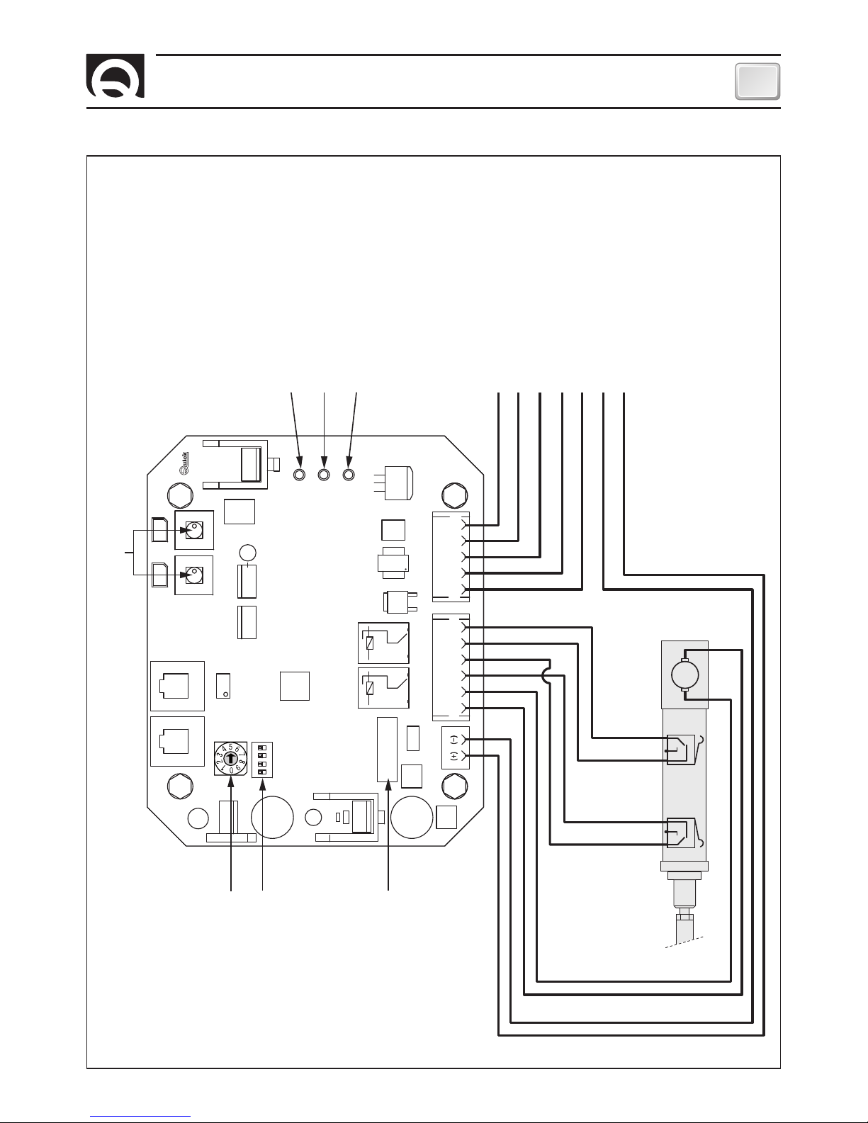
CONNECTION DIAGRAM
Negative group reversing contactor
To left contactor
To right contactor
TCD Plugin female Pin 2
TCD Plugin female Pin 1
- Power Supply
+ Power Supply
Rotary switch
actuator current limit
Dip-Switch
options selection
Fuse Actuator
M
1
2
3
4
5
6
7
10 A
CN1
CN2
CAN1
CAN2
UP
DWN
CN3
POWER
DL3
DL2
DL1
LA STATUS
ERROR
LA
+
LA
-
LSC COM COM C
-
COMC
-
SXC
-
DXI
-
SXI
-
DXLSO
RTC R1 BOARD
Manual operation buttons
Green LED power
CAN bus link
Bi-colour LED linear actuator status
Red LED errors
LINEAR ACTUATOR
Red
Red
Black
Yellow
Green
White
Page 32

32
EN
RETRACTABLE THRUSTER BTR250 - IT EN - REV08B
OPERATING
Option selection Dip-Switch
SWITCH FUNCTION DESCRIPTION
1
Reserved (always keep off)
ON
1 2 3 4
2
Informs the CAN control station that the thruster is in the bow (OFF)
ON
1 2 3 4
Informs the CAN control station that the thruster is in the stern (ON)
ON
1 2 3 4
3
Reserved (always keep off)
ON
1 2 3 4
4
Reserved (always keep off)
ON
1 2 3 4
FACTORY SETTING: 1 = OFF , 2 = OFF , 3 = OFF , 4 = OFF
Actuator current rotary switch
The ten selectable steps (from 0 to 9) allow you to set a percentage (see table) regarding the maximum current/load allowed for
the actuator in use.
ROTARY SWITCH POSITION MAXIMUM CURRENT/LOAD %
0
28%
1
36%
2
44%
3
52%
4
60%
5
68%
6
76%
7
84%
8
92%
9
100%
Should a setting different to the factory one be requested, carry out the following operations:
1) Turn the arrow of the rotary switch to the desired position with the board not powered.
2) When the board is powered, the percentage corresponding to the selected position will automatically be set.
If the maximum current/load is too low compared to the real operating requirements, may intervene protections against high
absorption of the actuator in closing and opening the retractable, with flashing 1 and 7 errors.
Page 33

33
EN
RETRACTABLE THRUSTER BTR250 - IT EN - REV08B
NOTIFICATION SIGNS
LED LA STATUS (bi-colour)
LED POWER (green)
LED STATUS DESCRIPTION
OFF
Board not powered
SLOW FLASHING
Powered board but disabled control
FAST FLASHING
Powered board and actuator’s manual movement mode on
ON WITH SHORT SWITCHING OFF
Powered board but disabled control and active link with the CAN control station
ON
Powered board and enabled control (TCD or CAN station).
LED COLOUR LED STATUS DESCRIPTION
- OFF
With powered board, actuator’s manual movement mode on and limit switch anomaly present
RED ON
Retractable thruster closed (LSC limit switch enabled)
GREEN ON
Retractable thruster open (LSO limit switch enabled)
ORANGE ON
Retractable thruster neither open nor closed (LSC and LSO limit switches disabled)
ORANGE FLASHING
Retractable thruster neither open nor closed (LSC and LSO limit switches disabled) and linear actuator moving.
NOTIFICATION SIGNS
Legend of error notifications concerning the RTC R1 board (see the board on page 31)
At the end of the cyclical flashing sequence, the “ERROR” LED remains off for a short period.
LED ERROR (red)
NUMBER OF FLASHING
DESCRIPTION
NOTHING
No anomaly present.
1
High absorption of the actuator during ascent (retractable thruster closing)
Signalling occurs after the system has attempted three ascents in the presence of mechanical friction exceeding the
set threshold. The problem can be caused by a foreign body that entered the mechanism, by the vessel navigating at
sustained speed, or by mechanical problems of the retractable and relative hatch.
2
Open fuse.
A current absorption exceeding 10A has occurred. The problem can arise from a short circuit or an overload on the actuator power line. Verify the wiring of the power lines from the board to the actuator or the absorption of the actuator itself.
3
Anomalous limit switch’s condition.
The problem is signalled when the board detects an anomaly on the limit switches (both activated). Verify the wiring of
the power lines from the board to the limit switches and their functionality.
4
Actuator command line interruption:
The problem is signalled when the board detects an interruption in the command power lines of the actuator. Verify the
wiring of the power lines from the board to the actuator.
5
Timeout of actuator’s movement intervention.
The problem is signalled when the movement command given to the actuator is not executed within 15 seconds.
6
Mistaken dip-switch setting.
The problem is signalled when the dip-switch positions have not been set correctly.
7
High absorption of the actuator during descent (retractable thruster opening).
Signalling occurs after the system has attempted three descents in the presence of mechanical friction exceeding the
set threshold. The problem can be caused by a foreign body that entered the mechanism, by the vessel navigating at
sustained speed, or by mechanical problems of the retractable thruster and relative hatch.
8
High absorption on motor reversing contactor unit control’s output.
The problem is signalled when the board detects a short circuit or an overload on the electric control line of the propeller.
Verify the wiring on the power lines from the board to the propeller and the absorption of the motor reversing contactor unit installed on the propeller.
9
Activation of the thermal protection on the motor
The problem is notified in case the thermal protection on the motor is tripped.
Wait for the thruster to cool off.
Interrupted connection on the motor reversing contactor unit control’s output.
The problem is signalled when the board detects an interruption on the electric control line of the propeller.
Verify the wiring of the power lines from the board to the motor reversing contactor unit installed on the propeller.
Page 34

34
EN
RETRACTABLE THRUSTER BTR250 - IT EN - REV08B
WARNING - OPERATION/USAGE
OPERATION / USE OF RETRACTABLE THRUSTER
To correctly use the retractable thruster, refer to the TCD control manual
Start-up
When switching on, the RTC R1 board verify the position of the retractable thruster (raised, lowered or in an intermediate position). If it is raised, the system does not execute any actions. If it is lowered or in the intermediate position, it will command the
ascent of the retractable thruster.
Enabling control from TCD (Retractable thruster descent)
When the RTC R1 board is enabled by a TCD control, the retractable thruster begins its descent.
The left/right commands from the TCD are inhibited until this operation is complete. During the descent phase, the RTC R1 board
measures the current absorbed by the linear actuator. If mechanical friction causes elevated absorption in the linear actuator,
the descent will be reversed briefly and then restart. After 3 attempts, the RTC R1 board will signal the problem.
Disabling control from TCD (Retractable thruster ascent)
When the RTC R1 board is disabled by a TCD control, the retractable thruster begins its ascent.
The right/left commands from the TCD are inhibited during the ascent. During the ascent phase, the RTC R1 boards measures the
current absorbed by the linear actuator. If mechanical friction causes an elevated absorption in the linear actuator, the ascent
will be reversed briefly and then restart. After 3 attempts, the RTC R1 board will signal the problem.
Automatic ascent in case of time out TCD
With the propeller lowered, after 6 minutes from last TCD right or left control, the retractable thruster performs the ascent procedure.
Errors detection from TCD
In case TCD sends an error signal in network (prolonged control, line interruption, short circuit in right or left output), the
retractable thruster performs the ascent procedure.
WARNING
WARNING: this bow thruster is not designed for continuous use.
It is equipped with protections which limit its operation at a maximum time span, as reported on the controls’ manual.
It is strongly forbidden to bypass or modify such protections in order to increase the operating time span, lest voiding the
warranty and thus lifting any responsibility from Quick SPA.
WARNING: before starting the retractable thruster ensure there are no bathers and floating objects near-by.
WARNING: To prevent any damage to the system, it is recommended not to sail with the open retractable thruster; to
perform the thruster’s opening and closing at a maximum speed of 4 knots, according to the currents, and at a maximum
speed of 2 knots, still according to the currents, if reversing.
WARNING: to avoid damaging the system, it is recommended not enable the retractable thruster at speeds over four
nodes.
WARNING: there must not be flammable materials in the peak or in the area where the Bow Thruster motor is.
WARNING: during mooring, it is recommended not to leave in the water any free line, which may be sucked in by the
propellers, thus leading them to break (fig. 26).
Fig. 26
Page 35

35
EN
RETRACTABLE THRUSTER BTR250 - IT EN - REV08B
IN EMERGENCY, THE PROPELLER CAN BE LOCKED IN THE CLOSED POSITION
WARNING: disconnect the BTR propeller from power.
On the actuator, under the plastic cover there is a slotted screw; turn it clockwise with a screwdriver to close the system.
THRUSTER’S CLOSING PROBLEMS
ACTUATOR
PLASTIC COVER
SLOTTED SCREW
Page 36

36
EN
RETRACTABLE THRUSTER BTR250 - IT EN - REV08B
75
7
8
14
13
13
12
12
11
11
10
26
18
17
15
16
27
17
28
18
22
25
17
23
48
49
66
65
49
63
59
51
32
47
46
45
38
41
41
40
40
42
43
39
67 69
74
68
72
70
73
71
44
24
50
54
53
52
51
55
56
57
74
49
44
48
61
62
60
62
29
30
31
32
33
34
35
36
37
64
65
49
66
10
58
9
6
6
5
1
2
3
87
4
21
20
19
82
83
84
81
28
28
17
17
78
79
80
85
86
76
43
77
MAINTENANCE
88
BTR 2512024
BTR 2514024
BTR 2524024
Page 37

37
EN
RETRACTABLE THRUSTER BTR250 - IT EN - REV08B
MAINTENANCE
Quick® Thrusters are made in materials that are
resistant to the sea environment: In any case, it is
indispensable to periodically remove salt deposits
that form on the outer surfaces to avoid corrosions
and consequent system inefficiency.
WARNING: make sure that the power supply
to the electric motor is not switched on when
maintenance operations are carried out.
Dismantle once a year, following the points below:
• Clean propellers (63 and 64), tunnel (59) and
gearleg (61).
• Replace the zinc anodes (carry out this operation
more often if needed)
• Replace the propellers if damaged or worn out.
• Check the tightness of all screws.
• Ensure that there is no water seepage inside.
• Check that all electrical connections are well
tightened and oxide-less.
• Check that the batteries are in good conditions.
WARNING: do not paint the zinc anodes (40
and 65), the sealings and the gearlegs’ shafts
where the propellers are lodged.
N
DESCRIPTION
1
Screw
2
Washer
3
Motor
4
Reversing contactor unit
5
Carter reversing contactor
6
Fasteners carter reversing
contactor
7 Screw
8 Flange
9 Chassis
10 O-ring
11 Oil seal
12 Fixation ring
13 Screw
14 Pin
15 Actuator’s lever
16 Pin
17 Washer
18 Spring ring
19 RRC RX box
20 Cable outlet
21 Screw
22 Washer
23 Fulcrum
24 Pin
25 Screw
26 Actuator
27 Actuator’s plate
28 Self-locking nut
29 Oil seal
30 External circlip
31 Shaft
32 Key
33 Bearing
34 External circlip
35 Shaft support
36 Oil seal
37 Double joint
38 Tilting body
39 Spring
40 Anode
41 Screw
42 Screw
43 Grower
44 Oil seal
45 Key insert
46 Grower
47 Screw
48 Washer
49 Nut
50 O-ring
51 Bearing
52
External circlip
53
Internal circlip
54 Oil seal
55 Cable-stopper
56 Screw
57 Nut
58 Shaft
59 Tunnel
60 Gasket
61 Gearleg
62 Key
63 Propeller 250 L
64 Propeller 250 R
65 Anode
66 Screw
67 Washer
68 Self-locking nut
69 Washer
70 Screw
71 Nut
72 Screw
73 Cable guide
74 Nut
75 Gasket
76 Washer
77 Screw
78 Hinge’s shaft
79 Hinge’s bracket
80 Washer
81 Hinge’s arm
82 Lid’s bracket
83 Screw
84 Angle bar
85 Washer
86 Self-locking nut
87 Motor key
88 Cable
Page 38

38
EN
RETRACTABLE THRUSTER BTR250 - IT EN - REV08B
SPARE PARTS
1
6
4
2 3
5
7
8
Page 39

39
EN
RETRACTABLE THRUSTER BTR250 - IT EN - REV08B
SPARE PARTS
N. DESCRIPTION CODE
1A OSP MOTOR 10KW 24V BTR250+T FVEMFEL1K24B25T
1B OSP MOTOR 6500W 24V BTR250+T FVEMFEL6524B25T
1C OSP MOTOR 8000W 24V BTR250+T FVEMFEL8024B25T
2A OSP KIT REVERSING CONTACTOR UNIT 350A 12V FVSGRCT35012A00
2B OSP KIT REVERSING CONTACTOR UNIT 350A 24V FVSGRCT35024A00
3 OSP KIT CARTER ‘B’ FOR PROPELLER FVSGCARTABTQB00
4 OSP KIT THERMIC PROTECTION BTR FVKPS120BTR0A00
5 OSP KIT ANODS FOR PROPELLER BTR FVSGANBTR250A00
6 OSP KIT GEARLEG BTR250 FVSGGBBTR250A00
7 OSP KIT PROPELLER D250 R FVSGEL250R00A00
8 OSP KIT PROPELLER D250 L FVSGEL250L00A00
9 OSP ANGLE BAR FISS VERT CERN BTR250 FVSLPVNG2500A00
10 OSP KIT HINGE+LID’S BRACKET BTR250 FVSGCN250000A00
11 OSP KIT STEEL CABLE BTR250 COMPLET FVSFBTR25000A00
9
10 11
Page 40

40
RETRACTABLE THRUSTER BTR250 - IT EN - REV08B
200 (7
7
/8)
160 (6
19
/64)
65 (2
9
/16)
A
B
570 (22
7
/16)
800 (31 1/2)
ELICA DI MANOVRA RETRATTILE BTR250 - DIMENSIONI mm (inch)
RETRACTABLE THRUSTER BTR250 - DIMENSIONS mm (inch)
MOD. BTR2512024 BTR2514024 BTR2524024
A - mm (inch)
1011 (39” 13/16) 1008 (39” 11/16) 1071 (42” 5/32)
B - mm (inch)
457 (18”) 457 (18”) 510 (20” 3/32)
Page 41

41
RETRACTABLE THRUSTER BTR250 - IT EN - REV08B
NOTES
Page 42

NOTES
Page 43

Page 44

THRUSTER RETRACTABLE
BTR250
Codice e numero seriale del prodotto
Product code and serial number
EN
IT
QUICK® S.p.A. - Via Piangipane, 120/A - 48124 Piangipane (RAVENNA) - ITALY
Tel. +39.0544.415061 - Fax +39.0544.415047
www.quickitaly.com - E-mail: quick@quickitaly.com
R008
b
 Loading...