

Page 1
REV 003A
High
Quality
Nautical
Equipment
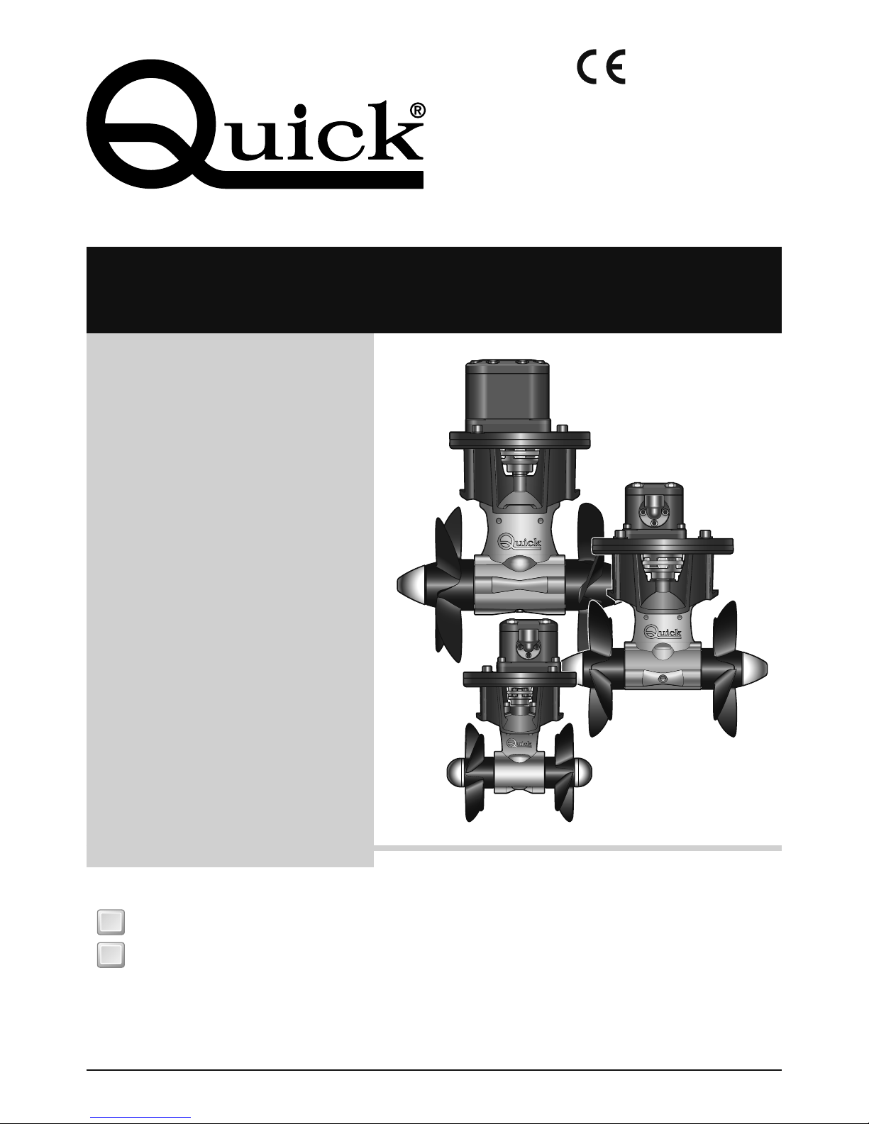
HYDRAULIC THRUSTER
BT185HY080
BT185HY100
BT250HY150
BT250HY220
BT300HY240
BT300HY300
Manuale d'uso ELICHE DI MANOVRA IDRAULICHE
User's Manual HYDRAULIC THRUSTERS
IT
GB
Page 2

Page 3

BOW THRUSTER BTHY185-250-300 IT GB - REV003A
3
Pag. 4 CARATTERISTICHE E INSTALLAZIONE
Pag. 5/6 INSTALLAZIONE - requisiti per l’installazione - il tunnel
Pag. 7 INSTALLAZIONE - il thruster
Pag. 8 INSTALLAZIONE - il piede e la flangia di supporto motore
Pag. 9 INSTALLAZIONE - montaggio dell’elica
Pag. 10 SCHEMA DI COLLEGAMENTO
Pag. 11 CARATTEISTICHE D’IMPIANTO - USO
Pag. 12/13 MANUTENZIONE BTHY185
Pag. 14/15 MANUTENZIONE BTHY250
Pag. 16/17 MANUTENZIONE BTHY300
INDICE
Pag. 18 CHARACTERISTICS AND INSTALLATION
Pag. 19/20 INSTALLATION - installation requirements - the tunnel
Pag. 21 INSTALLATION - the thruster
Pag. 22 INSTALLATION - gearleg and motor support flange
Pag. 23 INSTALLATION - propeller fitting
Pag. 24 CONNECTION DIAGRAM
Pag. 25
SYSTEM CHARACTERISTICS
- USAGE
Pag. 26/27 MAINTENANCE BTHY185
Pag. 28/29 MAINTENANCE BTHY250
Pag. 30/31 MAINTENANCE BTHY300
INDEX
IT
GB
Page 4

4
CARATTERISTICHE E INSTALLAZIONE
IT
BOW THRUSTER BTHY185-250-300 IT GB - REV003A
PRIMA DI UTILIZZARE L’ELICA DI MANOVRA IDRAULICA LEGGERE ATTENTAMENTE IL PRESENTE
MANUALE D'USO. IN CASO DI DUBBI CONSULTARE IL RIVENDITORE QUICK
®
.
ATTENZIONE: Le eliche di manovra Quick® sono state progettate e realizzate per asservire all’uso nautico.
Non utilizzare questi apparecchi per altri tipi di applicazioni. Quick® non si assume alcuna responsabilità per
i danni diretti o indiretti causati da un uso improprio dell’apparecchio o da una scorretta installazione.
L’elica di manovra non è progettata per mantenere carichi generati in particolari condizioni atmosferiche
(burrasca). Si raccomanda di affidare a un professionista la predisposizione e il posizionamento del
tubo allo scafo. Queste istruzioni sono generiche, e non illustrano in alcun modo i dettagli delle operazioni
di predisposizione del tunnel quale competenza del cantiere. In caso di eventuali problemi provocati da
un’installazione difettosa del tunnel, ne risponderà in pieno l’installatore.
Non installare il motore idraulico nelle vicinanze di oggetti facilmente infiammabili.
LA CONFEZIONE CONTIENE: elica di manovra idraulica - dima di foratura - o-ring (per l'assemblaggio) - manuale di
istruzioni - condizioni di garanzia.
ATTREZZI NECESSARI PER L'INSTALLAZIONE:
BTHY185: trapano con punta da Ø 9 mm (3/8"); a tazza Ø 32 mm (1"1/4); chiavi maschio esagonale: 5 mm, 6 mm, 8 mm,
chiave a forchetta o poligonale: 19.
BTHY250: trapano con punta da Ø 11 mm (7/16"); a tazza Ø 46 mm (1"13/16); chiavi maschio esagonale: 4mm, 5mm,
8mm, 10mm; chiave a forchetta o poligonale: 24.
BTHY300: trapano con punta da Ø 15 mm (19/32"); a tazza Ø 53 mm (2"3/32); chiavi maschio esagonale: 4mm, 5mm,
8mm, 12mm; chiave a forchetta o poligonale: 27.
ACCESSORI QUICK
®
CONSIGLIATI: TCD 1022 - TCD 1042 - TCD1044 - TCD1062 - TMS - TSC
NOTA: Il motore idraulico delle eliche di manovra Quick è del tipo reversibile ad ingranaggi. La sua efficienza
è condizionata dall’energia idraulica fornitagli dalla centrale oleodinamica cui è connesso. In particolare sarà
influenzato dal numero di giri del motore principale, se è questo che alimenta la pompa, e/o da altre utenze
idrauliche alimentate nello stesso momento.
MODELLI BT185HY080 BT185HY100 BT250HY150 BT250HY220 BT300HY240 BT300HY300
N° Eliche 2 controrotanti
Tunnel Ø 185 mm (7” 19/64) 250 mm (9” 27/32) 300 mm (11” 13/16)
Tipologia motore Reversibile ad ingranaggi
Cilindrata 4,5 cc (0,27in3) 6,4 cc (0,39in3) 9,6 cc (0,59in3) 14,1 cc (0,86in3) 17,9 cc (1,09in3) 22 cc (1,34in3)
Massima pressione
di punta
270 bar (3920 psi) 250 bar (3625 psi) 225 bar (3260 psi) 250 bar (3625 psi)
Flangiatura porte
(A e B
)
(1)
Ø 30 mm Ø 40 mm
Foratura porte (A e B)
(1)
M6 M8
Foratura drenaggio (C)
(1)
G1/4 G3/8
Peso
Spessori limite
dei tunnel
min. 6 mm - max 12 mm
(min. 15/64” - max 15/32”)
min. 7 mm - max 12 mm
(min. 9/32” - max 15/32”)
min. 8 mm - max 13 mm
(min. 5/16” - max 1/2”)
VALORI DI REGOLAZIONE (consigliati da Quick)
Portata
17,0 lt/min
(4,5U SGpm)
28,0 lt/min
(7,4U SGpm)
25,5 lt/min
(6,75 USGpm)
41,5 lt/min
(11,0 USGpm)
42,5 lt/min
(11,3 USGpm)
60,0 lt/min
(15,9 USGpm)
Pressione
250 bar
(3625 psi)
190 bar
(2760 psi)
240 bar
(3480 psi)
180 bar
(2610 psi)
220 bar
(3190 psi)
225 bar
(3260 psi)
Potenza idraulica
assorbita
7,1 kw (9,6 Hp) 8,9 kw (12,1 Hp) 10,2 kw (13,9 Hp) 12,5 kw (17 Hp) 15,6 kw (21,2 Hp) 22,5 kw (30,6 Hp)
Potenza meccanica
all’elica
5,6 kw (7,6 Hp) 7,1 kw (9,6 Hp) 8,2 kw (11,2 Hp) 10 kw (13,6 Hp) 12,5 kw (17 Hp) 18 kw (24,5 Hp)
Spinta 80 Kgf (176 lbs) 100 Kgf (220 lbs) 150 Kgf (330 lbs) 220 Kgf (485 lbs) 240 Kgf (545 lbs) 300 Kgf (660 lbs)
(1)
Vedi schema di collegamento a pag. 10
F
Page 5
5
INSTALLAZIONE
IT
BOW THRUSTER BTHY185-250-300 IT GB - REV003A
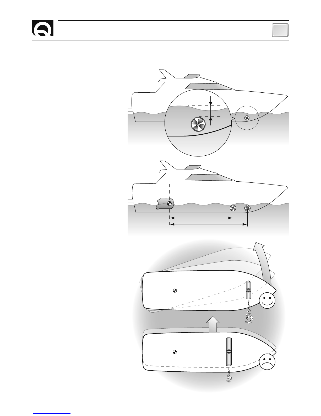
• Per evitare fenomeni di cavitazione
nell’elica, si dovrà posizionare il tunnel
più a fondo possibile.
• L’effetto di leva nell’imbarcazione
è proporzionale all’aumento della
distanza (L1 e L2) che si rileva, tra il
baricentro e la posizione del tunnel A
e B.
Per avere maggiore effetto leva
preferire la posizione B alla posizione A.
minimo 0,75 volte
Ø
tunnel
BARICENTRO
L 1
L 2
AB
REQUISITI PER L'INSTALLAZIONE
IL TUNNEL
• L’aumento della lunghezza del tunnel
aumenta l’effetto delle perdite di
carico diminuendo la forza nominale di
propulsione.
• Per limitare le perdite di carico, la
lunghezza consigliata è pari a 3-4 volte
il diametro del tubo; è tollerato un
rapporto fino a 6 volte il diametro.
• La posizione del tunnel dipenderà
dalla forma interna ed esterna della
prua della imbarcazione.
• La sistemazione ottimale del tunnel,
sarà più a prua e più a fondo possibile,
minimo 0,75 volte il diametro del tunnel
dalla linea di galleggiamento.
F
Page 6
6
IT
BOW THRUSTER BTHY185-250-300 IT GB - REV003A
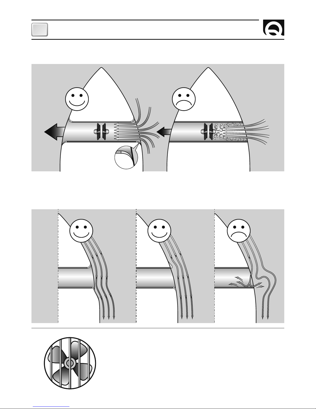
• Le estremità arrotondate del tunnel limitano l’innesco di turbolenze e cavitazione, migliorando le prestazione della
spinta dell’elica e riducendo al minimo la rumorosità.
• Quando l’imbarcazione è in movimento, la forza prodotta dal flusso dell’acqua produce della resistenza sulla faccia
posteriore del tunnel, che diventa un’area piatta al flusso dell’acqua. Per limitare questo fenomeno, prevedere una
rientranza nella parte posteriore del tunnel. Questa dipenderà dalla sagoma dello scafo dell’imbarcazione, o in alternativa, realizzare un deflettore nella parte anteriore del tunnel.
• Nel caso in cui il tunnel sia vicino alla linea di galleggiamento è consigliabile
prevedere l’inserimento di una grata all’estremità del tubo.
La grata deve avere maglie verticali e più larghe possibili, per non contrastare
la spinta dell’elica.
Le maglie verticali impediscono l’ingresso della maggior parte degli oggetti
galleggianti.
INSTALLAZIONE
Page 7
7
INSTALLAZIONE
IT
BOW THRUSTER BTHY185-250-300 IT GB - REV003A
7
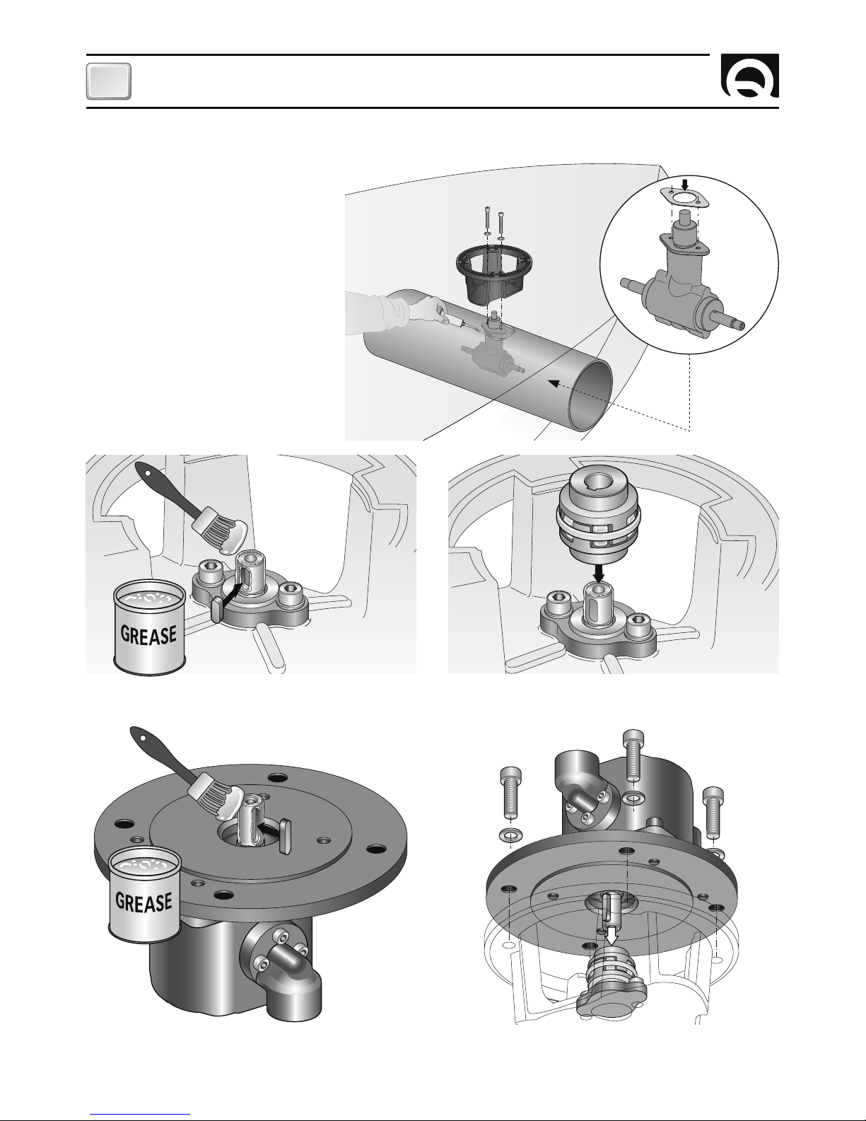
IL THRUSTER
• Utilizzare la flangia per contrassegnare sul tubo il centro dei fori.
• Fissare la dima di foratura sui riferimenti accertandosi
che siano allineati con precisione alla mezzeria del tubo.
N.B. Tutti i fori devono essere allineati con precisione alla
mezzeria del tunnel, in quanto la tolleranza tra l’elica ed i
tunnel è minima.
• Fare attenzione che non vi siano residui di resina nella
parte di contatto fra la flangia e il tubo; ciò potrebbe causare disallineamenti. E’ necessario asportare con carta
vetrata eventuali residui di resina e di tutti gli eventuali
impedimenti al corretto contatto.
• Il thruster può essere installato con qualunque angolo
all’interno di 90º dalla verticale.
• Il motore idraulico non necessita di supporti o sostegni.
10 23456 78910
• Inserire due o-ring nelle specifiche sedi all’interno della
flangia.
• Per posizionare correttamente il thruster trovare la
mezzeria del tubo.
Page 8
8
IT
BOW THRUSTER BTHY185-250-300 IT GB - REV003A
8
IL PIEDE RIDUTTORE E LA FLANGIA DI SUPPORTO MOTORE
S
I
L
I
C
O
N
E
• Ingrassare la parte terminale dell’albero del piede
riduttore; montare la chiavetta nella propria sede.
• Inserire il giunto elastico nella parte terminale dell’albero del piede riduttore.
• Inserire il motore sul giunto elastico, fissare con le 4 viti
e rondelle in dotazione.
• Ingrassare la parte terminale dell’albero motore; montare la chiavetta nella propria sede.
• Procedere al montaggio del piede riduttore con la specifica guarnizione di
tenuta.
• Come ulteriore precauzione contro l’ingresso d’acqua, applicare silicone per
uso nautico nella zona di contatto tra
flangia e tubo.
• Fissare il tutto con la flangia utilizzando
le specifiche viti e rondelle.
INSTALLAZIONE
Page 9
9
INSTALLAZIONE
IT
BOW THRUSTER BTHY185-250-300 IT GB - REV003A
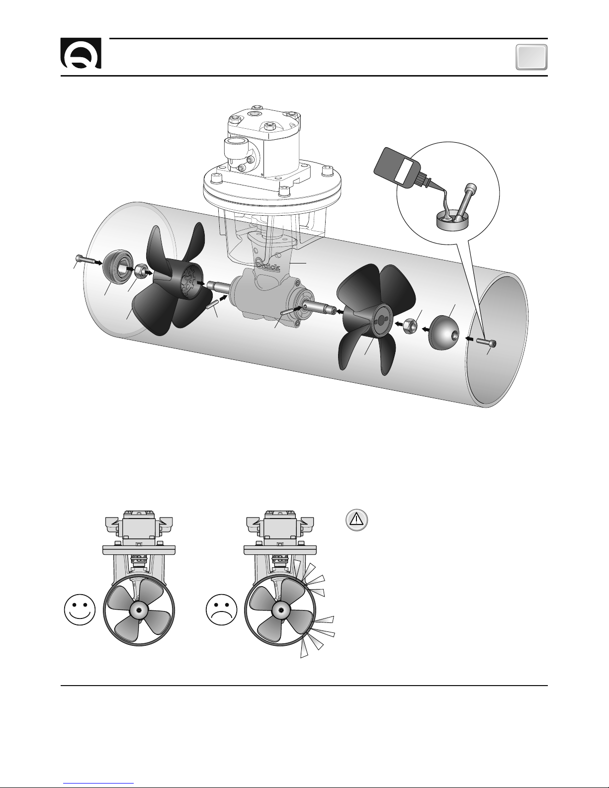
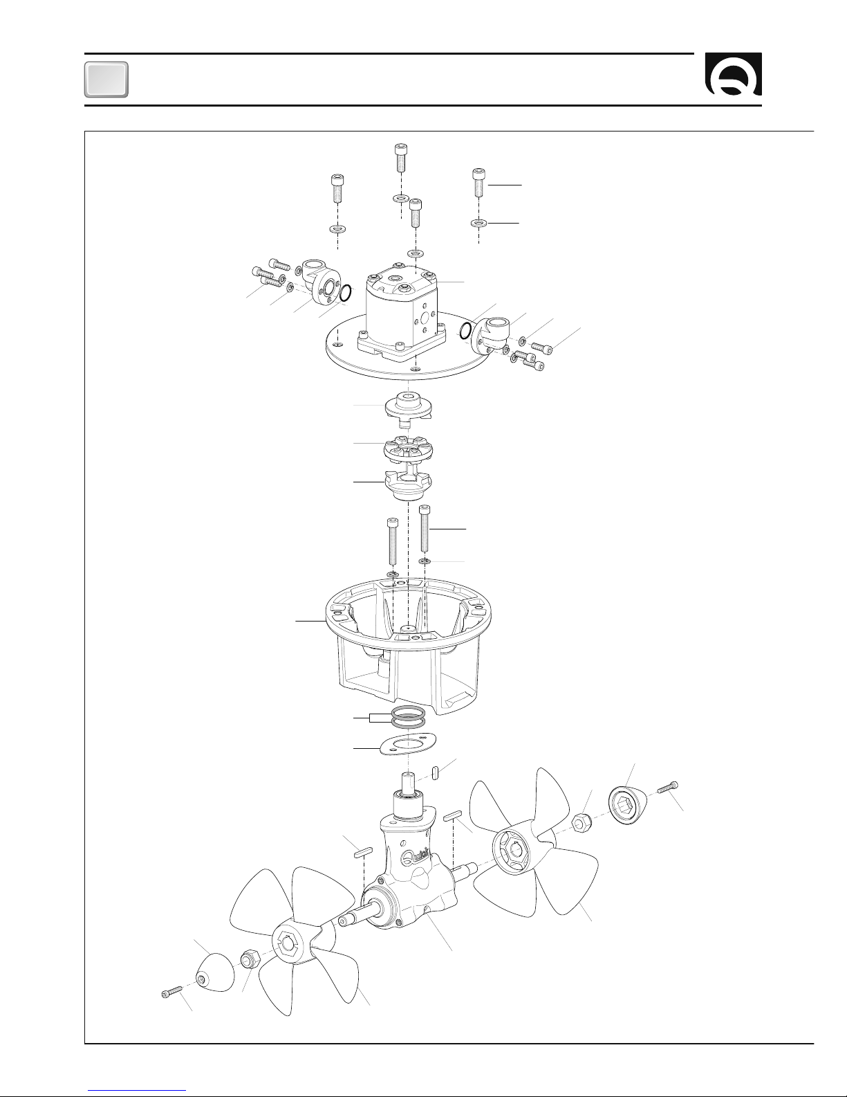
L’ELICA
PANNELLO DI COMANDO
Per l’installazione del pannello di comando, fare riferimento ai manuali d’uso dei “TCD 1022 - TCD 1042 - TCD 1044 - TCD
1062”.
LO
CTITE
ATTENZIONE: accertarsi, ad assemblaggio
ultimato, che le eliche siano ben centrate
all’interno del tunnel.
MONTAGGIO DELLE ELICHE
Inserire le spine di trascinamento A nei fori sugli alberi del piede riduttore B, assemblare le eliche C al riduttore ingranandole alle spine di trascinamento A, fissare le eliche con i dadi autofrenanti D. Gli anodi E vanno bloccati con le viti F
bagnate con adesivo strutturale (tipo loctite).
A
C
D
E
F
A
B
C
D
E
F
Page 10
10
IT
BOW THRUSTER BTHY185-250-300 IT GB - REV003A
SISTEMA BASE
BTHY185 - BTHY250 - BTHY300
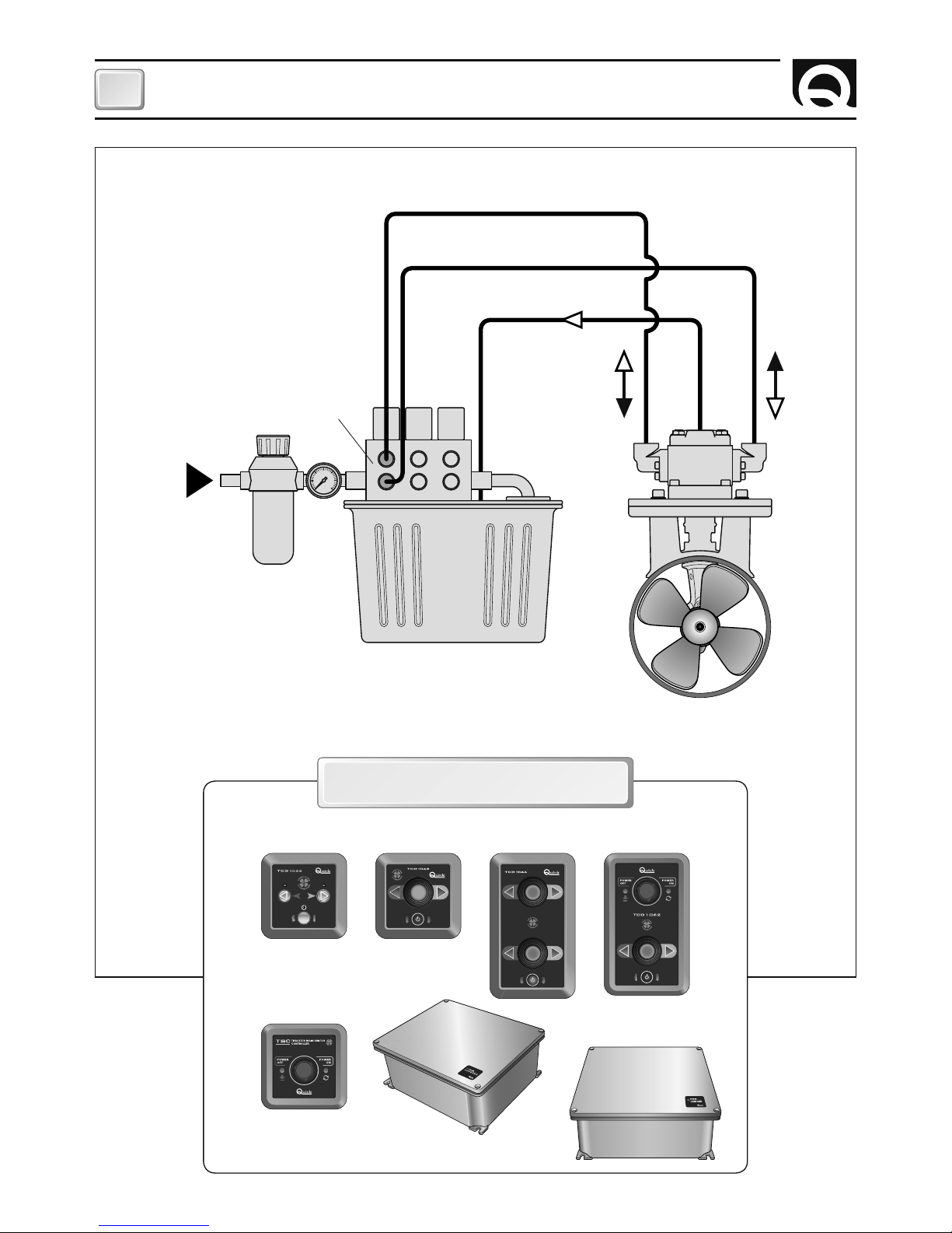
SCHEMA DI COLLEGAMENTO
INGRESSO
PRESSIONE
AB
C
ELICA DI MANOVRA
SERBATOIO
VALVOLA
DISTRIBUTRICE
PANNELLI DI COMANDO
ACCESSORI QUICK® PER L'AZIONAMENTO
DELL’ELICA DI MANOVRA IDRAULICA
COMANDO
INTERRUTTURE
DI LINEA TSC
INTERRUTTORE BATTERIE
PARALLELO-SERIE PSS
INTERRUTTORE
DI LINEA TMS
TCD 1022 TCD 1042
STERN
BOW
TCD 1044 TCD 1062
Page 11

11
IT
BOW THRUSTER BTHY185-250-300 IT GB - REV003A
AVVERTENZE IMPORTANTI
ATTENZIONE: accertarsi che non vi siano bagnanti ed oggetti galleggianti nelle vicinanze, prima d’avviare il
thruster.
NOTA:
il thruster idraulico è un componente di impianto. L’impianto deve avere determinate caratteristiche.
CARATTERISTICHE D’IMPIANTO
• L’iniziale livello di contaminazione del fluido usato per riempire l’impianto non dovrebbe superare la classe 18/15 (rif.
ISO 4406). Tale livello dovrebbe essere mantenuto da una adeguata filtrazione, garantita appunto dal filtro dell’impianto,
secondo tabella.
CARATTERISTICHE D’IMPIANTO - USO
F
USO DEL THRUSTER IDRAULICO
Accensione
L’accensione avviene in conseguenza all’attivazione di un pannello TCD.
Per l’uso dell’elica retrattile fare riferimento al manuale del comando TCD.
• L’impianto dovrà avere un filtro per mantenere l’olio esente da impurità.
• Si consiglia l’installazione di uno scambiatore o di utilizzare un serbatoio dell’olio ben dimensionato permettendo così
che la temperatura massima dell’olio rimanga compresa in quelle consigliate per il fluido idraulico utilizzato.
• Si raccomanda l’uso di fluidi specifici per circuiti idraulici a base d’olio minerale, con buone caratteristiche antiusura
e antischiuma, con proprietà di rapida disaerazione, antiossidanti, anticorrosione, lubrificanti e in grado di soddisfare
quanto previsto dalla norma DIN 51525 e dalla norma VDMA 24317, con viscosità cinematica compresa tra 10cSt e
100cSt.
• Le temperature di servizio dovranno essere comprese tra i -10°C e +80°C.
• La totalità dell’impianto idraulico è responsabilità dell’installatore il quale, secondo specifiche descritte e le esigenze di
servizio deve preservare il propulsore da potenziali danneggiamenti derivanti dall’impianto stesso.
• Il motore non deve essere utilizzato con pressioni superiori a quelle indicate.
• Valori superiori possono compromettere irreparabilmente l’integrità del motore stesso.
• Seguire attentamente le indicazioni di Quick per ottenere la massima efficienza dal vostro oggetto; in condizioni di
regolazioni diverse, non superare i valori massimi di pressione indicati in tabella.
• In nessun caso la pressione massima nel ramo di drenaggio dovrà superare i 6bar.
• E’ raccomandata l’installazione una valvola limitatrice di pressione (tarata al 10% - 15% superiore alla pressione massima di servizio nella valvola di controllo) per proteggere il sistema da eventuali danni derivati da un blocco meccanico
del sistema.
• E’ raccomandata l’installazione di un sistema, elettronico o idraulico, che ritardi l’inversione di moto del motore al fine
di preservare il riduttore da rotture.
Pressione <140 bar 140÷210 bar >210 bar
Classe NAS 1638 10 9 8
Classe ISO 4406 19/16 18/15 17/14
Rapporto βx = 75
25-40 µm 12-15 µm 6-12 µm
Quick® si riserva il diritto di apportare modifiche alle caratteristiche tecniche dell'apparecchio e al contenuto di questo manuale senza alcun preavviso.
In caso di discordanze o eventuali errori tra il testo tradotto e quello originario in italiano, fare riferimento al testo italiano o inglese.
F
Page 12
12
IT
BOW THRUSTER BTHY185-250-300 IT GB - REV003A
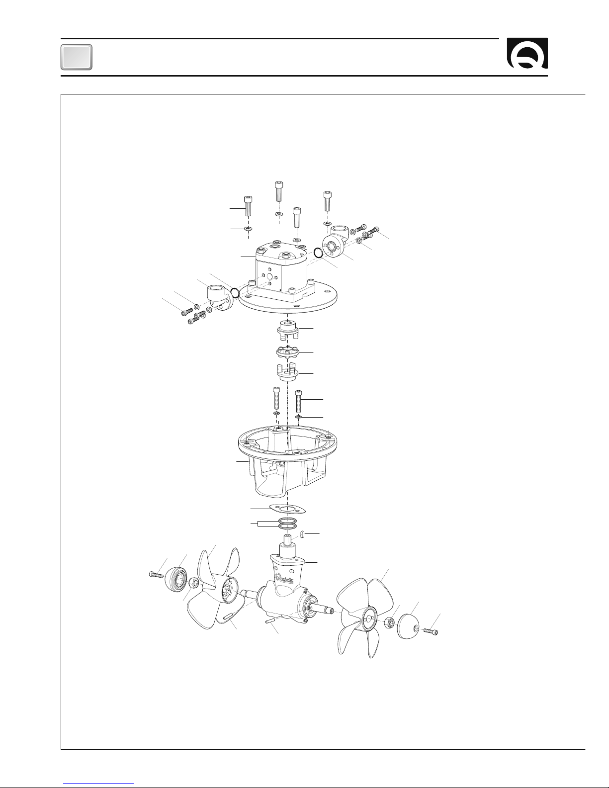
1
2
13
12
8
9
10
11
3
5
4
7
6
5
4
7
6
14
15
16
19
21
22
23
17
18
22
21
20
23
18
BT 185HY080
BT 185HY100
MANUTENZIONE
Page 13

13
IT
BOW THRUSTER BTHY185-250-300 IT GB - REV003A
ATTENZIONE : accertarsi che non sia presente l’alimentazione al motore idraulico quando si eseguono le operazioni di manutenzione.
I Thruster Quick
®
sono costituiti da materiale resistenti all’ambiente marino: è indispensabile, in ogni caso, rimuovere periodicamente i depositi di sale che si formano sulle superfici
esterne per evitare corrosioni e di conseguenza inefficienza
del sistema.
Smontare una volta all’anno, seguendo i seguenti punti:
• Tenere le eliche (19) e piede riduttore (16) puliti.
• Verniciare le eliche e il piede riduttore con vernice antivege-
tativa, prima di ogni stagione.
ATTENZIONE : non verniciare gli anodi di zinco (22), le
sigillature e gli alberi delle eliche. Fare attenzione a non
far penetrare la vernice nelle “piste” del piede riduttore
(16) nelle quali si muovono i mozzi delle eliche.
• Controllare gli anodi di zinco (22) frequentemente.
• Sostituire gli anodi di zinco prima di ogni stagione o quando
sono consumati per più della metà.
• Accertarsi dopo ogni manutenzione, che le viti (11), che
fissano la flangia (13) al piede riduttore (16), siano ben strette.
• Accertarsi dopo ogni manutenzione che le eliche (19 e 20)
siano ben fissate e le viti (1) che fissano il motore idraulico (3)
siano ben strette.
• Effettuare rabbocchi senza mescolare diversi fluidi idraulici.
• Verificare periodicamente l’integrità delle connessioni idrauli-
che ed intervenire su di esse solo con la certezza che non vi
sia pressione al loro interno.
POS.
DENOMINAZIONE CODICE
1 Vite fissaggio motore
MBV1025MXCEO
2 Rondella fissaggio motore
MBR10X000000
3A Motore ad ingranaggi
4,5CC Bidirezionale
MTG2AR045A00
3B Motore ad ingranaggi
6,4CC Bidirezionale
MTG2AR064A00
4
O-ring 2.5x16mm
PGRM25160000
5 Flangetta 90°
G1/2 femmina D30
MNFL90F12D30
6
Grower
MBR08X000000
7 Vite M8x30
MBV0830MXCE0
8 Semigiunto
MMSGM1100000
9 Parastrappi
PVPR43000000
10 Semigiunto
MMSMG1542H00
11 Vite fissaggio riduttore
MBV0850MXCE0
12 Grower
MBR08X000000
13 Flangia motore
SGMMEM185000
14 Guarnizione riduttore
PGRDEL185000
15 O-Ring
PGR031250000
16 Piede riduttore
SLMREM185D00
17 Chiavetta
MBH050515F00
18 Spina trascinamento elica
MBSC05025A00
19 Elica RH
PVEL18500000
20 Elica LH
PVEL185L0000
21 Dado fissaggio elica
MBD12MXET000
22 Puntale anodico
MMANBTQ18500
23 Vite fissaggio
puntale anodico
MBV0625MXCE0
MANUTENZIONE
Page 14

14
IT
BOW THRUSTER BTHY185-250-300 IT GB - REV003A
13
11
15
14
12
10
9
8
4
7
7
4
5
6
16
3
23
20
23
21
17
17
22
19
18
21
22
2
1
5
6
MANUTENZIONE
BT 250HY150
BT 250HY220
Page 15

15
IT
BOW THRUSTER BTHY185-250-300 IT GB - REV003A
ATTENZIONE : accertarsi che non sia presente l’alimentazione al motore idraulico quando si eseguono le operazioni di manutenzione.
I Thruster Quick
®
sono costituiti da materiale resistenti all’ambiente marino: è indispensabile, in ogni caso, rimuovere periodicamente i depositi di sale che si formano sulle superfici
esterne per evitare corrosioni e di conseguenza inefficienza
del sistema.
Smontare una volta all’anno, seguendo i seguenti punti:
• Tenere eliche (19 e 20) e piede riduttore (18) puliti.
• Verniciare le eliche e il piede riduttore con vernice antivege-
tativa, prima di ogni stagione.
ATTENZIONE : non verniciare gli anodi di zinco (22), le
sigillature e l’albero dell’elica. Fare attenzione a non far
penetrare la vernice nelle “piste” del piede riduttore (18)
nelle quali si muovono i mozzi delle eliche.
• Controllare gli anodi di zinco (22) frequentemente.
• Sostituire gli anodi di zinco prima di ogni stagione o quando
sono consumati per più della metà.
• Accertarsi dopo ogni manutenzione, che le viti (11), che
fissano la flangia (13) al piede riduttore (18), siano ben strette.
• Accertarsi dopo ogni manutenzione che le eliche (19 e 20)
siano ben fissate e le viti (1) che fissano il motore idraulico (3)
siano ben strette.
• Effettuare rabbocchi senza mescolare diversi fluidi idraulici.
• Verificare periodicamente l’integrità delle connessioni idrauli-
che ed intervenire su di esse solo con la certezza che non vi
sia pressione al loro interno.
POS.
DENOMINAZIONE CODICE
1 Vite fissaggio motore
MBV1025MXCEO
2 Rondella fissaggio motore
MBR10X000000
3A Motore ad ingranaggi
9,6CC Bidirezionale
MTG2AR096A00
3B Motore ad ingranaggi
14,1CC Bidirezionale
MTG2AR141A00
4
O-ring 2.5x16mm
PGRM25160000
5 Flangetta 90°
G3/4 femmina D40
MNFL90F12D40
6 Grower
MBR08X000000
7 Vite M8x30
MBV0830MXCE0
8 Semigiunto
MMSMG2270H00
9 Parastrappi
PVPR43000000
10 Semigiunto
MMSMG1900000
11 Vite fissaggio riduttore
MBV1050MXCE0
12 Grower Ø10
MBG10X000000
13 Flangia motore
SLMMEM250000
14 O-Ring
PGR041750000
15 Guarnizione riduttore
PGRDEL250000
16 Chiavetta 6x6x20
MBH0606020X0
17 Chiavetta 6x6x40
MBH0606040X0
18 Piede riduttore
MREM25000000
19 Elica destra
PVEL25R00000
20
Elica sinistra
PVEL25L00000
21
Dado autofrenante M16
MBD16MXET000
22
Puntale anodico
MMANBTQ25000
23 Vite fissaggio
puntale anodico
MBV0635MXCE0
MANUTENZIONE
Page 16

16
IT
BOW THRUSTER BTHY185-250-300 IT GB - REV003A
15
14
23
22
21
13
11
16
20
21
17
19
18
17
12
10
9
22
23
8
2
1
4
5
6
7
6
7
4
5
3
2
1
MANUTENZIONE
BT 300HY240
BT 300HY300
Page 17

17
IT
BOW THRUSTER BTHY185-250-300 IT GB - REV003A
ATTENZIONE : accertarsi che non sia presente l’alimentazione al motore idraulico quando si eseguono le operazioni di manutenzione.
I Thruster Quick
®
sono costituiti da materiale resistenti all’ambiente marino: è indispensabile, in ogni caso, rimuovere periodicamente i depositi di sale che si formano sulle superfici
esterne per evitare corrosioni e di conseguenza inefficienza
del sistema.
Smontare una volta all’anno, seguendo i seguenti punti:
• Tenere eliche (19 e 20) e piede riduttore (18) puliti.
• Verniciare le eliche e il piede riduttore con vernice antivege-
tativa, prima di ogni stagione.
ATTENZIONE : non verniciare gli anodi di zinco (22), le
sigillature e l’albero dell’elica. Fare attenzione a non far
penetrare la vernice nelle “piste” del piede riduttore (18)
nelle quali si muovono i mozzi delle eliche.
• Controllare gli anodi di zinco (22) frequentemente.
• Sostituire gli anodi di zinco prima di ogni stagione o quando
sono consumati per più della metà.
• Accertarsi dopo ogni manutenzione, che le viti (11), che
fissano la flangia (13) al piede riduttore (18), siano ben strette.
• Accertarsi dopo ogni manutenzione che le eliche (19 e 20)
siano ben fissate e le viti (1) che fissano il motore idraulico (3)
siano ben strette.
• Effettuare rabbocchi senza mescolare diversi fluidi idraulici.
• Verificare periodicamente l’integrità delle connessioni idrauli-
che ed intervenire su di esse solo con la certezza che non vi
sia pressione al loro interno.
MANUTENZIONE
POS.
DENOMINAZIONE CODICE
1 Vite fissaggio motore
MBV1025MXCEO
2 Rondella fissaggio motore
MBR10X000000
3A Motore ad ingranaggi
17,9CC Bidirezionale
MTG2AR179A00
3B Motore ad ingranaggi
22CC Bidirezionale
MTG3AR220A00
4
O-ring 2.5x16mm
PGRM25160000
5 Flangetta 90°
G3/4 femmina D40
MNFL90F12D40
6 Grower
MBR08X000000
7 Vite M8x30
MBV0830MXCE0
8 Semigiunto
MMSMG2270H00
9 Parastrappi
PVPR70000000
10 Semigiunto
MMSMG2400000
11 Vite fissaggio riduttore M14
MBV1475MXCE0
12 Grower Ø14
MBR14X000000
13 Flangia motore
SLMMEM300000
14 O-Ring
PGR041750000
15 Guarnizione riduttore
PGRDEL300000
16 Chiavetta 8x7x25
MBH0807025X0
17 Chiavetta 8x7x50
MBH0807050X0
18 Piede riduttore
MREM30000000
19 Elica destra
PVEL30R00000
20 Elica sinistra
PVEL30L00000
21
Dado autofrenante M18
MBD18MXET000
22
Puntale anodico
MMANBTQ30000
23 Vite fissaggio
puntale anodico
MBV0635MBCE0
Page 18

18
CHARACTERISTICS AND INSTALLATION
GB
BOW THRUSTER BTHY185-250-300 IT GB - REV003A
BEFORE USING THE HYDRAULIC THRUSTER, READ THIS INSTRUCTION MANUAL CAREFULLY.
IF IN DOUBT, CONTACT YOUR NEAREST QUICK
®
DEALER.
WARNING: Quick® Thrusters have been designed and constructed only for nautical use.
Do not use these appliances for other uses.
Quick® shall accept no responsibility for direct or indirect damages caused by improper use of the appliance or
an improper installation.
The Thruster is not designed to maintain loads generated in particular atmospheric conditions (storms).
We recommend you entrust preparation and positioning of the tube on the hull to a skilled professional. These
are generic instructions and do not give details of the preparatory operations for installing the tunnel, since this is
the competence of the boatyard. The installer shall bear full responsibility for any problems caused by defective
installation of the tunnel.
Do not install the hydraulic motor near easily inflammable objects.
THE PACKAGE CONTAINS: hydraulic thruster - drill template - o-ring (for assembly) - user's manual - conditions of warranty.
TOOLS REQUIRED FOR INSTALLATION:
BTHY185: drill and drill bits Ø 9 mm (3/8"); hollow mill Ø 32 mm (1"1/4); hexagonal male key: 5 mm, 6 mm, 8 mm, fork
or polygonal key: 19.
BTHY250: drill and drill bits Ø 11 mm (7/16"); hollow mill Ø 46 mm (1"13/16); hexagonal male key: 4mm, 5mm, 8mm,
10mm; fork or polygonal key: 24.
BTHY300: drill and drill bits Ø 15 mm (19/32"); hollow mill Ø 53 mm (2"3/32); hexagonal male key: 4mm, 5mm, 8mm,
12mm; fork or polygonal key: 27.
“QUICK
®
”ACCESSORIES RECOMMENDED: TCD 1022 - TCD 1042 - TCD1044 - TCD1062 - TMS - TSC.
NOTE: Quick thrusters’ hydraulic motor is a reversible gear-type motor. Its efficiency is a result of the power
system it is connected to. It will be especially affected by the number of turns of the main motor, if this one feeds
the pump, and/or the latter is supplying power to other hydraulic systems during bow thruster operation.
F
MODELS BT185HY080 BT185HY100 BT250HY150 BT250HY220 BT300HY240 BT300HY300
N° Propellers 2 contra-rotating
Tunnel Ø 185 mm (7” 19/64) 250 mm (9” 27/32) 300 mm (11” 13/16)
Motor type reversible gear-type
Motor power 4,5 cc (0,27in3) 6,4 cc (0,39in3) 9,6 cc (0,59in3) 14,1 cc (0,86in3) 17,9 cc (1,09in3) 22 cc (1,34in3)
Peak maximum
pressure
270 bar (3920 psi) 250 bar (3625 psi) 225 bar (3260 psi) 250 bar (3625 psi)
Ports (A and B)
flanging
(1)
Ø 30 mm Ø 40 mm
Ports (A and B) drilling
(1)
M6 M8
Drain drilling (C)
(1)
G1/4 G3/8
Weight
Limit thickness
values of the tunnel
min. 6 mm - max 12 mm
(min. 15/64” - max 15/32”)
min. 7 mm - max 12 mm
(min. 9/32” - max 15/32”)
min. 8 mm - max 13 mm
(min. 5/16” - max 1/2”)
SETTING VALUES (SUGGESTED BY QUICK)
Flow rate
17,0 lt/min
(4,5U SGpm)
28,0 lt/min
(7,4U SGpm)
25,5 lt/min
(6,75 USGpm)
41,5 lt/min
(11,0 USGpm)
42,5 lt/min
(11,3 USGpm)
60,0 lt/min
(15,9 USGpm)
Pression
250 bar
(3625 psi)
190 bar
(2760 psi)
240 bar
(3480 psi)
180 bar
(2610 psi)
220 bar
(3190 psi)
225 bar
(3260 psi)
Hydraulic power
absorbed
7,1 kw (9,6 Hp) 8,9 kw (12,1 Hp) 10,2 kw (13,9 Hp) 12,5 kw (17 Hp) 15,6 kw (21,2 Hp) 22,5 kw (30,6 Hp)
Mechanical power to
the propeller
5,6 kw (7,6 Hp) 7,1 kw (9,6 Hp) 8,2 kw (11,2 Hp) 10 kw (13,6 Hp) 12,5 kw (17 Hp) 18 kw (24,5 Hp)
Thrust 80 Kgf (176 lbs) 100 Kgf (220 lbs) 150 Kgf (330 lbs) 220 Kgf (485 lbs) 240 Kgf (545 lbs) 300 Kgf (660 lbs)
(1)
See connection diagram on page 24
Page 19

19
INSTALLATION
GB
BOW THRUSTER BTHY185-250-300 IT GB - REV003A
• To avoid cavitation in the propeller,
the tunnel must be positioned as low
as possible.
• The lever effect in the boat is proportional to the increase of the distance
(L1 and L2) between the barycentre and
the position of the tunnel A and B.
For greater lever effect prefer
position B to position A.
minimum 0.75
times tunnel Ø
BARYCENTRE
L 1
L 2
AB
INSTALLATION REQUISITES:
THE TUNNEL
• An increase in the length of the tunnel increases the effect of the loss of
charge, decreasing the nominal driving
force.
• To limit losing thrust, the optimal
length is equal to 3-4 times the tube
diameter; a ratio of up to 6 can be tolerated.
• The position of the tunnel will depend
on the interior and exterior shape of
the boats bow.
• Optimal positioning of the tunnel
will be in the bow and as low as possible, at least 0.75 times the tunnel
diameter from the waterline.
F
Page 20

20
GB
BOW THRUSTER BTHY185-250-300 IT GB - REV003A
• The rounded ends of the tunnel limit the creation of turbulences and cavitations, improving performance of the propeller thrust and reducing noise levels to a minimum.
• The force produced by the flow of the water when the boat is moving produces resistance on the rear face of the
tunnel, which is an area exposed frontally to the water flow.
To limit this phenomenon, prepare an indentation in the rear part of the tunnel. Otherwise, create a deflector on the
front part of the tunnel.
• If the tunnel is near the waterline, it is advisable to fit a grating at the
end of the tube.
The grating must have as large a vertical mesh as possible to avoid
contrasting the propeller thrust. The vertical mesh prevents the entry of
most of the floating objects.
INSTALLATION
Page 21

21
INSTALLATION
GB
BOW THRUSTER BTHY185-250-300 IT GB - REV003A
THE THRUSTER
To position the thruster in the tube, find the half-way
point.
• Use the flange to mark the centre of the holes on the
tube.
• Fix the drilling template on the reference points, making
sure they are aligned with precision at the half-way point
of the tube.
N.B. All holes must be exactly aligned with the half-way
point of the tunnel, since tolerance between propeller
and tunnel is minimal.
• Take care that there are no resin residues in the
contact area between flange and tube; this could cause
misalignment. Any resin residues and any other hindrance
to correct contact must be removed by sandpaper.
• The thruster can be installed at any angle within 90°
from vertical.
• Il motore idraulico non necessita di supporti o sostegni.
• Insert two o-rings into the special seats inside the
flange.
10 23456 78910
Page 22

22
GB
BOW THRUSTER BTHY185-250-300 IT GB - REV003A
GEARLEG AND MOTOR SUPPORT FLANGE
S
I
L
I
C
O
N
E
• Grease the terminal part of the gearleg shaft; fit the
small key into its seat.
• Insert the elastic joint in the terminal part of the gearleg shaft.
• Insert the motor onto the elastic joint; fasten it with the
4 screws and washers provided.
• Grease the terminal part of the gearleg shaft; fit the
small key into its seat.
• Proceed with fitting the gearleg with
the special seal gasket.
• For further protection against the entry of water, apply silicone for nautical
use around the point of contact between
flange and tube.
• Fasten everything to the flange using
the special screws and washers.
INSTALLATION
Page 23

23
INSTALLATION
GB
BOW THRUSTER BTHY185-250-300 IT GB - REV003A
PROPELLER
CONTROL PANEL
To install the control panel, consult the “TCD 1022 - TCD 1042 - TCD 1044 - TCD 1062” instruction manuals.
WARNING: on conclusion of assembly,
make sure that the propellers are exactly
positioned at the central point of the tunnel.
PROPELLER FITTING
Insert the drive pins A into the hole on the gearleg shafts B; assemble the propeller C to the gearleg, making it fit in cor-
rectly with the drive pins A; fix the propellers with the self-braking nuts D. The anodes E must be locked with the screws
F soaked with building adhesive (such as Loctite).
LO
CTITE
A
C
D
E
F
A
B
C
D
E
F
Page 24

24
GB
BOW THRUSTER BTHY185-250-300 IT GB - REV003A
CONNECTION DIAGRAM
BASIC SYSTEM
BTHY185 - BTHY250 - BTHY300
PRESSURE
INPUT
AB
C
THRUSTER
TANK
SELECTOR
VALVE
CONTROL PANELS
QUICK® ACCESSORIES FOR ACTIVATION
OF THE HYDRAULIC THRUSTER
TSC THRUSTER
MAIN SWITCH
COMMAND
PSS PARALLEL SERIES
BATTERY SWITCH
TMS THRUSTER
MAIN SWITCH
TCD 1022 TCD 1042
STERN
BOW
TCD 1044 TCD 1062
Page 25

25
GB
BOW THRUSTER BTHY185-250-300 IT GB - REV003A
SYSTEM CHARACTERISTICS - USAGE
WARNING
WARNING: make sure no swimmers or floating objects are in the vicinity before switching on the thruster.
NOTE:
the hydraulic thruster is a system component. The system must have these given characteristics.
SYSTEM CHARACTERISTICS
• The initial contamination level of the fluid used to fill the system shouldn’t exceed class 18/15 (ref. ISO 4406). Such a
level shall be kept by means of a suitable filtering, performed by the system filter itself, according to the chart below.
F
USE OF HYDRAULIC THRUSTER
Start-up
Start-up happens following activation of a TCD panel.
To use the retractable thruster refer to the manual of the TCD control.
• The system shall have a filter to keep the oil free from impurities.
• The installation of an exchanger or the use of a well-dimensioned oil tank is suggested, in order to prevent the oil
maximum temperature from exceeding the values recommended for the hydraulic fluid used.
• The use of specific fluids for hydraulic circuits with a mineral-oil base are recommended; they shall have good wearproof and antifoam features, with quick de-aeration, antioxidant, corrosion-inhibiting, lubricant properties, and shall be
compliant with the requirements of DIN 51525 and VDMA 24317 standards, with kinematic viscosity included between
10cSt and 100cSt.
• Operating temperatures shall be included in the range between -10°C and +80°C.
• The whole hydraulic system is responsibility of the installer, whom according to the described specifics and the operating requirements shall preserve the propeller from potential damages deriving from the system itself.
• The motor shall not be used with higher pressures than those indicated.
• Higher values may jeopardize irreparably the integrity of the motor itself.
• Follow carefully Quick indications to obtain the highest efficiency from your product: in different setting conditions, do
not exceed the maximum pressure values listed in the chart.
• In no case shall the maximum pressure in the draining arm exceed 6 bar.
• The installation of a pressure-relief valve (set at 10% - 15% higher than the maximum operating temperature of the
control valve) is recommended, in order to protect the system from any damage deriving from a mechanical stoppage
of the system.
• The installation of an electronic or hydraulic system, capable of delaying the motor motion reversal is recommended,
in order to preserve the gearbox from damages.
Pressure <140 bar 140÷210 bar >210 bar
Nas 1638 Class 10 9 8
ISO 4406 Class 19/16 18/15 17/14
ßx = 75 Ratio 25-40 µm 12-15 µm 6-12 µm
Quick® reserves the right to introduce changes to the equipment and the contents of this manual without prior notice.
In case of discordance or errors in translation between the translated version and the original text in the Italian language, reference will be made to the Italian or English text.
F
Page 26

26
GB
BOW THRUSTER BTHY185-250-300 IT GB - REV003A
MAINTENANCE
1
2
13
12
8
9
10
11
3
5
4
7
6
5
4
7
6
14
15
16
19
21
22
23
17
18
22
21
20
23
18
BT 185HY080
BT 185HY100
Page 27

27
GB
BOW THRUSTER BTHY185-250-300 IT GB - REV003A
MAINTENANCE
WARNING: make sure that the power supply to the
hydraulic motor is not switched on when maintenance
operations are carried out.
Quick
®
Thrusters are made in materials that are resistant to the
sea environment: In any case, it is indispensable to periodically
remove salt deposits that form on the outer surfaces to avoid
corrosions and consequent system inefficiency
Dismantle once a year, following the points below:
• Keep the propellers (19 and 20) and the gearleg (16) clean.
• Paint the propellers and the gearleg with anti-vegetative
paint before each season.
WARNING: do not paint the zinc anodes (22), the sealings and the propeller shafts. Be careful not to allow
paint to penetrate in the “tracks” of the gearleg (18) in
which the propeller hubs moves.
• Check the zinc anodes (22) frequently.
• Replace the zinc anodes before every season or when it is
more than half consumed.
• After any maintenance, make sure that the bolts (11) that lock
the flange (13) to the gearleg (18) are well tightened.
• After every maintenance, make sure that the propellers (19
and 20) is well tightened and that the bolts (1) locking the
hydraulic motor (3) are tight.
• Fill up without mixing different hydraulic fluids.
• Periodically verify the integrity of the hydraulic connections
and only operate on them when certain that there is no pressure inside.
POS.
DESCRIPTION CODE
1 Motor mounting screw
MBV1025MXCEO
2 Motor mounting washer
MBR10X000000
3A Bidirectional gear-type
motor 4,5CC
MTG2AR045A00
3B Bidirectional gear-type
motor 6,4CC
MTG2AR064A00
4
O-ring 2.5x16mm
PGRM25160000
5 Flange 90°
G1/2 female D30
MNFL90F12D30
6
Grower
MBR08X000000
7 Screw M8x30
MBV0830MXCE0
8 Half-joint
MMSGM1100000
9 Even tension device
PVPR43000000
10 Half-joint
MMSMG1542H00
11 Gearleg mounting screw
MBV0850MXCE0
12 Grower
MBR08X000000
13 Motor flange
SGMMEM185000
14 Gearleg gasket
PGRDEL185000
15 O-Ring
PGR031250000
16 Gearleg
SLMREM185D00
17 Key
MBH050515F00
18 Propeller drive pin
MBSC05025A00
19 RH Propeller
PVEL18500000
20 LH Propeller
PVEL185L0000
21 Propeller mounting nut
MBD12MXET000
22 Anode tip
MMANBTQ18500
23
Anode tip mounting screw
MBV0625MXCE0
Page 28
28
GB
BOW THRUSTER BTHY185-250-300 IT GB - REV003A
MAINTENANCE
13
11
15
14
12
10
9
8
4
7
7
4
5
6
16
3
23
20
23
21
17
17
22
19
18
21
22
2
1
5
6
BT 250HY150
BT 250HY220
Page 29

29
GB
BOW THRUSTER BTHY185-250-300 IT GB - REV003A
MAINTENANCE
WARNING: make sure that the power supply to the
hydraulic motor is not switched on when maintenance
operations are carried out.
Quick
®
Thrusters are made in materials that are resistant to the
sea environment: In any case, it is indispensable to periodically
remove salt deposits that form on the outer surfaces to avoid
corrosions and consequent system inefficiency.
Dismantle once a year, following the points below:
• Keep the propellers (19 and 20) and the gearleg (18) clean.
• Paint the propellers and the gearleg with anti-vegetative
paint before each season.
WARNING: do not paint the zinc anodes (22), the sealings and the propeller shafts. Be careful not to allow
paint to penetrate in the “tracks” of the gearleg (18) in
which the propeller hubs moves.
• Check the zinc anodes (22) frequently.
• Replace the zinc anodes before every season or when it is
more than half consumed.
• After any maintenance, make sure that the bolts (11) that lock
the flange (13) to the gearleg (18) are well tightened.
• After every maintenance, make sure that the propellers (19
and 20) is well tightened and that the bolts (1) locking the
hydraulic motor (3) are tight.
• Fill up without mixing different hydraulic fluids.
• Periodically verify the integrity of the hydraulic connections
and only operate on them when certain that there is no pressure inside.
POS.
DESCRIPTION CODE
1 Motor mounting screw
MBV1025MXCEO
2 Motor mounting washer
MBR10X000000
3A Bidirectional gear-type
motor 9,6CC
MTG2AR096A00
3B Bidirectional gear-type
motor 14,1CC
MTG2AR141A00
4
O-ring 2.5x16mm
PGRM25160000
5 Flangetta 90°
G3/4 femmina D40
MNFL90F12D40
6
Grower
MBR08X000000
7
Screw M8x30
MBV0830MXCE0
8 Half-joint
MMSMG2270H00
9 Even tension device
PVPR43000000
10 Half-joint
MMSMG1900000
11 Gearleg mounting screw
MBV1050MXCE0
12 Grower Ø10
MBG10X000000
13 Motor flange
SLMMEM250000
14 O-Ring
PGR041750000
15 Gearbox gasket
PGRDEL250000
16 Key 6x6x20
MBH0606020X0
17 Key 6x6x40
MBH0606040X0
18 Gearleg
MREM25000000
19 Starboard propeller
PVEL25R00000
20 Port propeller
PVEL25L00000
21 Self-braking nut M16
MBD16MXET000
22 Anode tip
MMANBTQ25000
23 Anode tip mounting screw
MBV0635MXCE0
Page 30

30
GB
BOW THRUSTER BTHY185-250-300 IT GB - REV003A
MAINTENANCE
15
14
23
22
21
13
11
16
20
21
17
19
18
17
12
10
9
22
23
8
2
1
4
5
6
7
6
7
4
5
3
2
1
BT 300HY240
BT 300HY300
Page 31

31
GB
BOW THRUSTER BTHY185-250-300 IT GB - REV003A
MAINTENANCE
WARNING: make sure that the power supply to the
hydraulic motor is not switched on when maintenance
operations are carried out.
Quick
®
Thrusters are made in materials that are resistant to the
sea environment: In any case, it is indispensable to periodically
remove salt deposits that form on the outer surfaces to avoid
corrosions and consequent system inefficiency.
Dismantle once a year, following the points below:
• Keep the propellers (19 and 20) and the gearleg (18) clean.
• Paint the propeller and the gearleg with anti-vegetative paint
before each season.
WARNING: do not paint the zinc anode (22), the sealings
and the propeller shaft Be careful not to allow paint to
penetrate in the “tracks” of the gearleg (18) in which the
propeller hub moves.
• Check the zinc anode (22) frequently.
• Replace the zinc anode before every season or when it is
more than half consumed.
• After any maintenance, make sure that the bolts (11) that lock
the flange (13) to the gearleg (18) are well tightened.
• After every maintenance, make sure that the propeller (19
and 20) is well tightened and that the bolts (1) locking the
hydraulic motor (3) are tight.
• Fill up without mixing different hydraulic fluids.
• Periodically verify the integrity of the hydraulic connections
and only operate on them when certain that there is no pressure inside.
POS.
DESCRIPTION CODE
1 Motor mounting screw
MBV1025MXCEO
2 Motor mounting washer
MBR10X000000
3A Bidirectional gear-type
motor 17,9CC
MTG2AR179A00
3B Bidirectional gear-type
motor 22CC
MTG3AR220A00
4
O-ring 2.5x16mm
PGRM25160000
5 Flange 90°
G3/4 female D40
MNFL90F12D40
6 Grower
MBR08X000000
7 Screw M8x30
MBV0830MXCE0
8 Half-joint
MMSMG2270H00
9 Even tension device
PVPR70000000
10 Half-joint
MMSMG2400000
11 Gearleg mounting screw M14
MBV1475MXCE0
12 Grower Ø14
MBR14X000000
13 Motor flange
SLMMEM300000
14 O-Ring
PGR041750000
15 Gearbox gasket
PGRDEL300000
16 Key 8x7x25
MBH0807025X0
17 Key 8x7x50
MBH0807050X0
18 Gearleg
MREM30000000
19 Starboard propeller
PVEL30R00000
20 Port propeller
PVEL30L00000
21
Self-braking nut M18
MBD18MXET000
22
Anode tip
MMANBTQ30000
23
Anode tip mounting screw
MBV0635MBCE0
Page 32

32
BOW THRUSTER BTHY185-250-300 IT GB - REV003A
185/100 = 177 (6
31
/
32
)
185/80 = 174,5 (6
7
/
8
)
Ø 197 (7
3
/
4
)
Ø 185 (7
9
/
32
)
Ø 266 (10
15
/32)
Ø 250 (9
27
/32)
250/220 = 209 (8
15
/
64
)
250/150 = 201 (7
29
/
32
)
THRUSTERS
DIMENSIONI / DIMENSIONS mm (inch)
BTHY185
BTHY250
Ø 332 (12
11
/16)
Ø 300 (11
11
/16)
300/300 = 246 (8
15
/
64
)
300/240 = 228 (7
29
/
32
)
BTHY300
Page 33

33
BOW THRUSTER BTHY185-250-300 IT GB - REV003A
THRUSTER
SISTEMA BASE / BASIC SYSTEM
• ENTRATA
PRESSIONE
• PRESSURE
INPUT
AB
C
• ELICA DI MANOVRA
• THRUSTER
• SERBATOIO • TANK
• VALVOLA DISTRIBUTRICE
• SELECTOR VALVE
Page 34

NOTES
Page 35

Page 36

QUICK® S.p.A. - Via Piangipane, 120/A - 48124 Piangipane (RAVENNA) - ITALY
Tel. +39.0544.415061 - Fax +39.0544.415047
www.quickitaly.com - E-mail: quick@quickitaly.com
Codice e numero seriale del prodotto
Product code and serial number
GB
IT
THRUSTERS
BTHY185 BTHY250 - BTHY300
R003A
 Loading...