

Page 1
Manuale d’uso BOILER SERIE B3
User’s Manual WATER HEATER SERIES B3
Manuel de l’utilisateur CHAUFFE-EAU SERIE B3
Benutzerhandbuch BOILER BAUREIHE B3
Manual del usuario CALENTADOR SERIE B3
Manual de uso AQUECEDOR SÉRIE B3
Bruksanvisning VATTENVÄRMARE SERIE B3
Handleiding BOILER SERIE B3
BOILER B3
B3 15
B3 20
B3 25
B3 30
B3 40
B3 60
B3 80
High Quality Nautical Equipment
REV 004B
IT
GB
FR
DE
ES
PT
SE
NL
Page 2

Page 3
3
BOILER B3 15-80 - REV004B
INDICE
INDEX
SOMMAIRE
INHALTSANGABE
INDICE
IT
GB
FR
DE
ES
ÍNDICE
INNEHÅLLSFÖRTECKNING
INDEX
PT
SE
NL
Pag. 4 Caratteristiche tecniche
Pag. 5 Installazione
Pag. 6 Schema di collegamento
Pag. 7 Uso - Avvertenze importanti
Pag. 8/9 Manutenzione
Pag. 10 Technical data
Pag. 11 Installation
Pag. 12 Connection diagram
Pag. 13 Usage - Warning
Pag. 14/15 Maintenance
Pag. 16 Caractéristiques techniques
Pag. 17 Installation
Pag. 18 Schéma de câblage
Pag. 19 Utilisation - Avvertissementes importants
Pag. 20/21 Entretien
Seite 22 Technische Eigenschaften
Seite 23 Installation
Seite 24 Anschlussplan
Seite 25 Gebrauch - Wichtige Hinweise
Seite 26/27 Wartung
Pág. 28 Características técnicas
Pág. 29 Instalación
Pág. 30 Esquema de montage
Pág. 31 Uso - Advertencias importantes
Pág. 32/33 Mantenimiento
Pág. 34 Características técnicas
Pág. 35 Instalação
Pág. 36 Esquema de conexão
Pág. 37 Uso - Avisos importantes
Pág. 38/39 Manutenção
Pag. 46 Technische eigenschappen
Pag. 47 Installatie
Pag. 48 Aansluitingsschema
Pag. 49 Gebruik - Belangrijke waarschuwingen
Pag. 50/51 Onderhoud
Sid. 40 Tekniska egenskaper
Sid. 41 Installation
Sid. 42 Kopplingsschema
Sid. 43 Användning - Viktiga föreskrifter
Sid. 44/45 Underhållsarbete
Page 4
4
BOILER B3 15-80 - REV004B
CARATTERISTICHE TECNICHE
IT
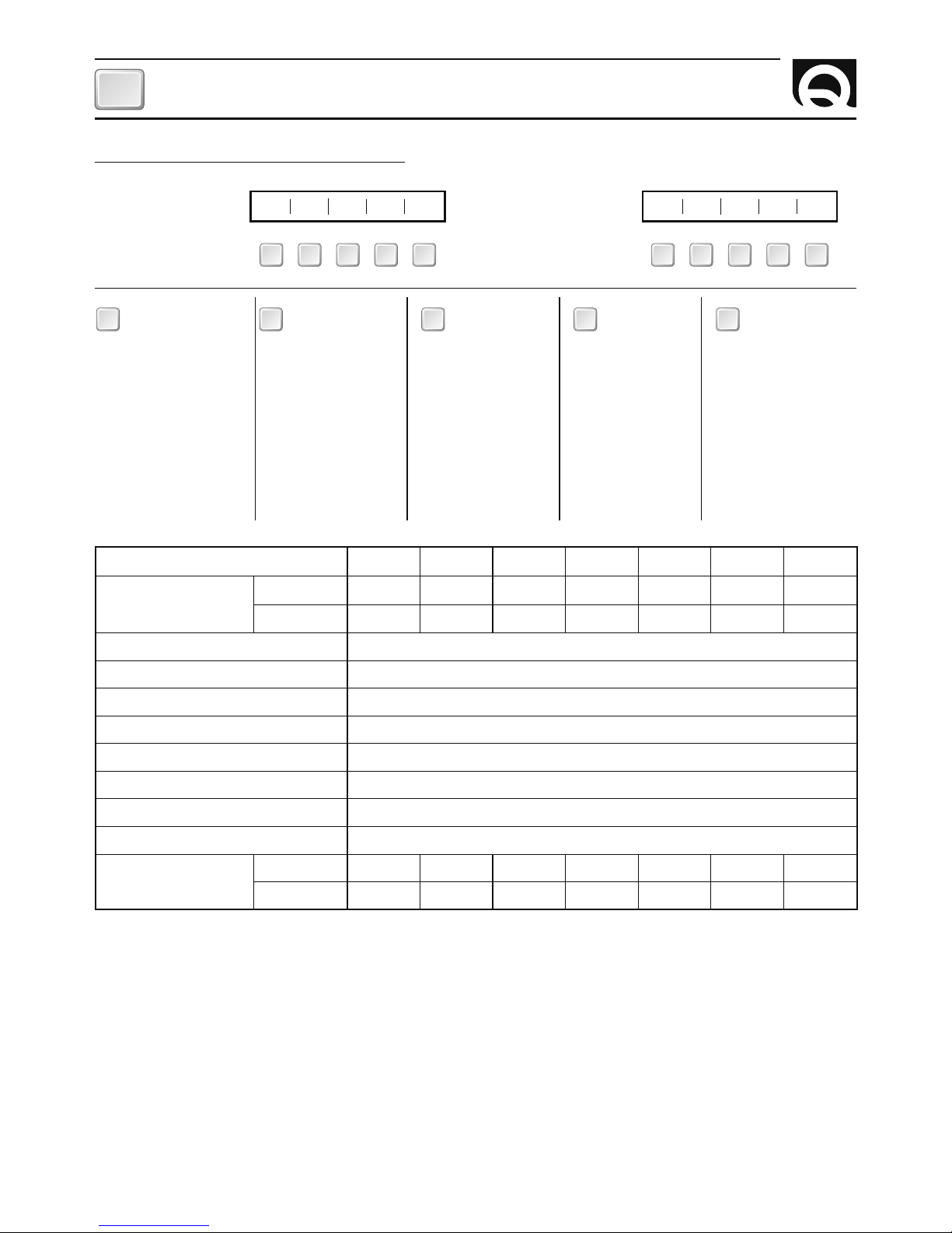
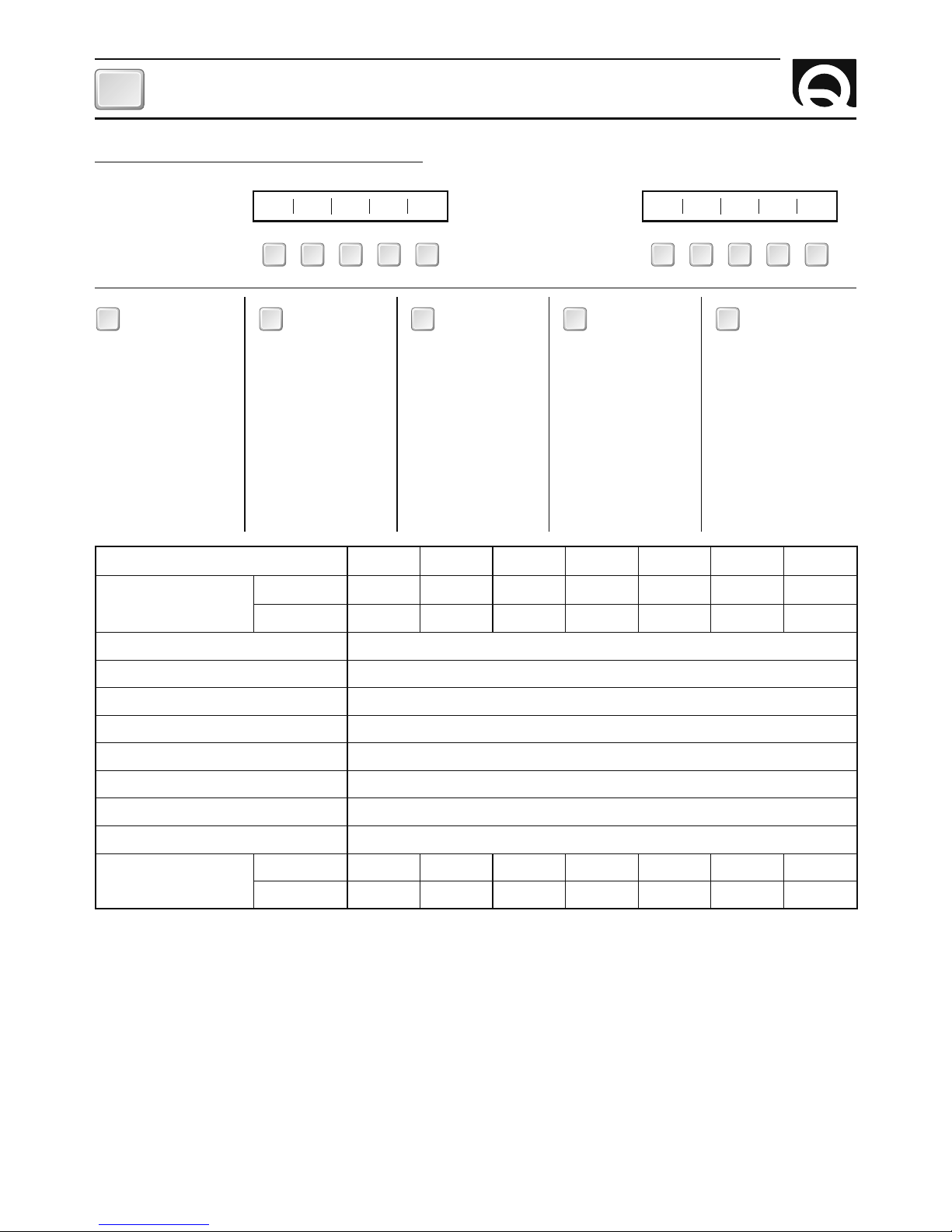
COME SI LEGGE IL MODELLO DEL BOILER:
(1)
1 Bar = 100 kPa
(2)
Diponibile su richiesta
(3)
A vuoto dell’apparecchio
(4)
Solo per 110 Vac
Quick® si riser va il diritto di a pportare mo difi che alle carat teristiche te cniche dell'appa recchio e al cont enuto di questo m anuale senza al cun preavvis o.
In caso di discordanze o eventuali errori tra il testo tradotto e quello originario in italiano, fare riferimento al testo italiano o inglese.
F
a b c d e
a
a
a
a
a
a b c d e
a
a
a
a
a
1° ESEMPIO : B32005S 2° ESEMPIO : B34012SL
B3 40 12 S LB3 20 05 S -
Nome
del prodotto:
[ B3 ] = Boiler in materiale
composito
Capacità del
serbatoio in litri:
[ 15 ] = 15 litri
[ 20 ] = 20 litri
[ 25 ] = 25 litri
[ 30 ] = 30 litri
[ 40 ] = 40 litri
[ 60 ] = 60 litri
[ 80 ] = 80 litri
Potenza della
resistenza elettrica:
[ 00 ] = non installata
[ 05 ] = 500 W
[ 06 ] = 600 W
(4)
[ 12 ] = 1200 W
Scambiatore
di calore:
[ S ] = presente
a
b dc
Tensione resistenza
elettrica (se installata):
[ - ] = 220 Vac
[ L ] = 110 vac
e
MODELLI
B3 15 B3 20 B3 25 B3 30 B3 40 B3 60 B3 80
CAPACITÀ SERBATOIO
Litri
15 20 25 30 40 60 80
USA gallone 3,96 5,28 6,6 7,92 10,56 15,85 21,13
Materiale serbatoio Acciaio inox
Isolante termico Poliuretano espanso rigido a cellule chiuse
Materiale rivestimento esterno Composito
Pressione serbatoio durante collaudo 800 kPa (1)
Pressione massima d’esercizio 600 kPa (1)
Tensione elemento riscaldante
(2)
220 Vac ± 10% - (110 Vac ± 10%)
Potenza elemento riscaldante
(2)
500 W [Modello 05] - 600 W [Modello 06]
(4)
- 1200 W [Modello 12]
Diametro raccordi 1/2”
Peso
(3)
Kg 6,2 7,1 8,1 10,5 12,0 13,4 16,3
Libbre 13.7 15.6 17.8 23.1 26.4 29.5 35.9
Page 5
5
BOILER B3 15-80 - REV004B
INSTALLAZIONE
IT
BOILER NAUTICO
La lunga esperienza maturata nel settore della nautica ci ha permesso di sviluppare una serie di boiler con caratteristiche innovative rispetto allo standard di mercato.
I vantaggi che i boiler nautici Quick
®
offrono sono:
• elevata qualità dei materiali che garantiscono lunga durata e resistenza.
• Scambiatore di calore dotato di notevole superfi cie di scambio.
• Possibilità di produrre acqua calda anche con la resistenza elettrica, completa di termostato di sicurezza
regolabile (nei modelli provvisti).
• Valvola di sicurezza e di ritegno che permette di scaricare l’acqua del boiler in caso di inutilizzo.
• Pratica installazione su piano.
PRIMA DI UTILIZZARE IL BOILER LEGGERE ATTENTAMENTE IL PRESENTE MANUALE DI ISTRUZIONI. IN CASO DI DUBBI CONSULTARE IL RIVENDITORE QUICK
®
.
ATTENZIONE: utilizzare il boiler solo per le applicazioni descritte in questo manuale. Non utilizzare
questo apparecchio per altri tipi di operazioni.
Quick® non si assume alcuna responsabilità per i danni
diretti o indiretti causati da un uso improprio dell’apparecchio.
LA CONFEZIONE CONTIENE: boiler - fasce per il fi ssaggio su piano o parete - viterie e minuterie varie (per
l’assemblaggio) - manuale d’uso - condizioni di garanzia.
AMBIENTE DI INSTALLAZIONE
Il boiler deve essere montato in un luogo asciutto e ben ventilato. Questa precauzione si rende necessaria, anche se il boiler è costruito con materiali resistenti all’ambiente marino, vista la presenza di dispositivi elettrici
(nei modelli provvisti). Inoltre l’installazione in ambienti non aerati potrebbe causare fenomeni di condensa; la
condensa può essere scambiata per una perdita che in realtà non esiste.
INSTALLAZIONE
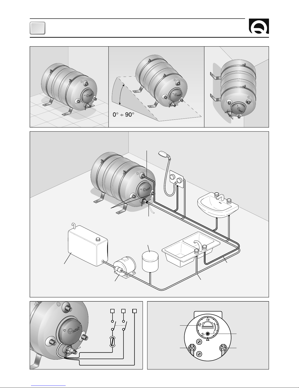
• Applicare le fasce (17) al serbatoio (1) utilizzando le viterie fornite a corredo (18, 19, 20).
• Fissare il boiler su piano, parete o piano inclinato come indicato in fi gura 1 utilizzando supporti idonei al peso
del boiler ed al tipo di piano o parete a disposizione per l’installazione.
ATTENZIONE: il peso del boiler indicato nelle caratteristiche tecniche è a vuoto. Per il peso a pieno carico aggiungere al peso a vuoto il peso della massa d’acqua contenuta (1 litro d’acqua corrisponde circa
ad 1 Kg. / 2,2 lb).
• Effettuare gli allacciamenti idraulici relativi all’entrata ed uscita dell’acqua sanitaria ed al circuito di raffreddamento del motore allo scambiatore di calore (nei modelli provvisti) come da fi gura 2. Rendere più corto
possibile il collegamento fra il circuito di raffreddamento del motore e lo scambiatore del boiler.
ATTENZIONE: il tubo di scarico della sovrapressione deve essere posizionato in pendenza continua verso il basso ed in luogo protetto dalla formazione di ghiaccio.
ATTENZIONE: l’acqua può gocciolare dal tubo di scarico del dispositivo contro le sovrapressioni e questo tubo deve essere lasciato aperto all’atmosfera.
ATTENZIONE: nel caso di montaggio di raccordi utilizzare Loctite 243, 577 o Tefl on.
Verifi care che non vi siano perdite d’acqua.
Page 6
BOILER B3 15-80 - REV004B
IT
6
SCHEMA DI COLLEGAMENTO
NEUTRO RETE AC FASE RETE AC
MANOPOLA
REGOLAZIONE
TEMPERATURA
PULSANTE
RIARMO
FASE NEUTRO TERRA
INTERRUTTORE
FUSIBILE
MARRONE
BLU
GIALLO / VERDE
FIG.3
FIG.1
FIG.2
LIQUIDO
RAFFREDDAMENTO
MOTORE
USCITA ACQUA
SANITARIA CALDA
INGRESSO ACQUA
SANITARIA FREDDA
SERBATOIO ACQUA
SANITARIA
AUTOCLAVE
ACQUA
FREDDA
ACQUA CALDA
VASO AD ESPANSIONE
FIG.4
Page 7
7
BOILER B3 15-80 - REV004B
IT
ATTENZIONE: seguire le istruzioni del fabbricante del motore per il prelievo del liquido di raffreddamento da inviare allo scambiatore del boiler.
• Applicare il tubo di scarico (6) alla valvola (4) serrandolo con la fascetta (5).
Posizionarlo in modo tale che l’eventuale fuoriuscita di acqua non danneggi altri oggetti.
• Aprire i rubinetti dell’acqua calda dei lavandini e avviare l’autoclave.
In questo modo viene fatta defl uire l’aria presente all’interno del boiler e nelle tubature.
Chiudere i rubinetti non appena comincia ad uscire solamente acqua.
• Verifi care che non vi siano perdite dai raccordi.
ALIMENTAZIONE ELETTRICA DELL’APPARECCHIO (nei modelli provvisti)
L’apparecchio è già dotato del cavo di alimentazione per la rete AC. Per i collegamenti alla rete AC vedere fi gura 3. Prima di alimentare il boiler accertarsi che la sua tensione di funzionamento corrisponda a quella fornita
dalla rete AC.
Nell’impianto elettrico deve essere installato un interruttore bipolare per accendere e spegnere l’apparecchio
ed un fusibile adeguato all’assorbimento. L’isolamento fra i contatti delle connessioni sulla rete AC deve essere
come minimo di 3 mm. Le connessioni alla rete AC devono essere realizzate in accordo alle norme nazionali
degli impianti elettrici.
ATTENZIONE: prima di effettuare il collegamento accertarsi che non sia presente l’alimentazione sui
cavi.
ATTENZIONE: nel caso in cui il cavo di alimentazione sia danneggiato, farlo sostituire da un centro
assistenza Quick. Per evitare incidenti l’apparecchio deve essere aperto solo da personale autorizzato.
L’apertura dell’apparecchio da parte di personale non autorizzato fa decadere la garanzia.
ATTENZIONE: non accendere mai la resistenza elettrica se il boiler non è pieno d’acqua pena un danneggiamento irreversibile dell’elemento riscaldante.
REGOLAZIONE DEL TERMOSTATO (nei modelli provvisti)
Il valore di temperatura impostato sul termostato dalla fabbrica è di 60°C. Se si desidera variare questo valore
seguire la procedura riportata di seguito:
• interrompere l’alimentazione elettrica.
• Smontare il coperchio di protezione (11) per accedere al termostato (9).
• Tramite un cacciavite agire sulla manopola del termostato (fi gura 4) ed impostare il valore di temperatura
desiderato.
• Montare il coperchio di protezione (11).
• Ripristinare l’alimentazione elettrica.
Il termostato regola la temperatura dell’acqua esclusivamente nel funzionamento con resistenza elettrica.
F
USO - AVVERTENZE IMPORTANTI
Page 8
8
BOILER B3 15-80 - REV004B
IT
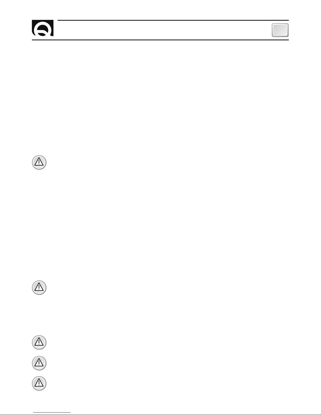
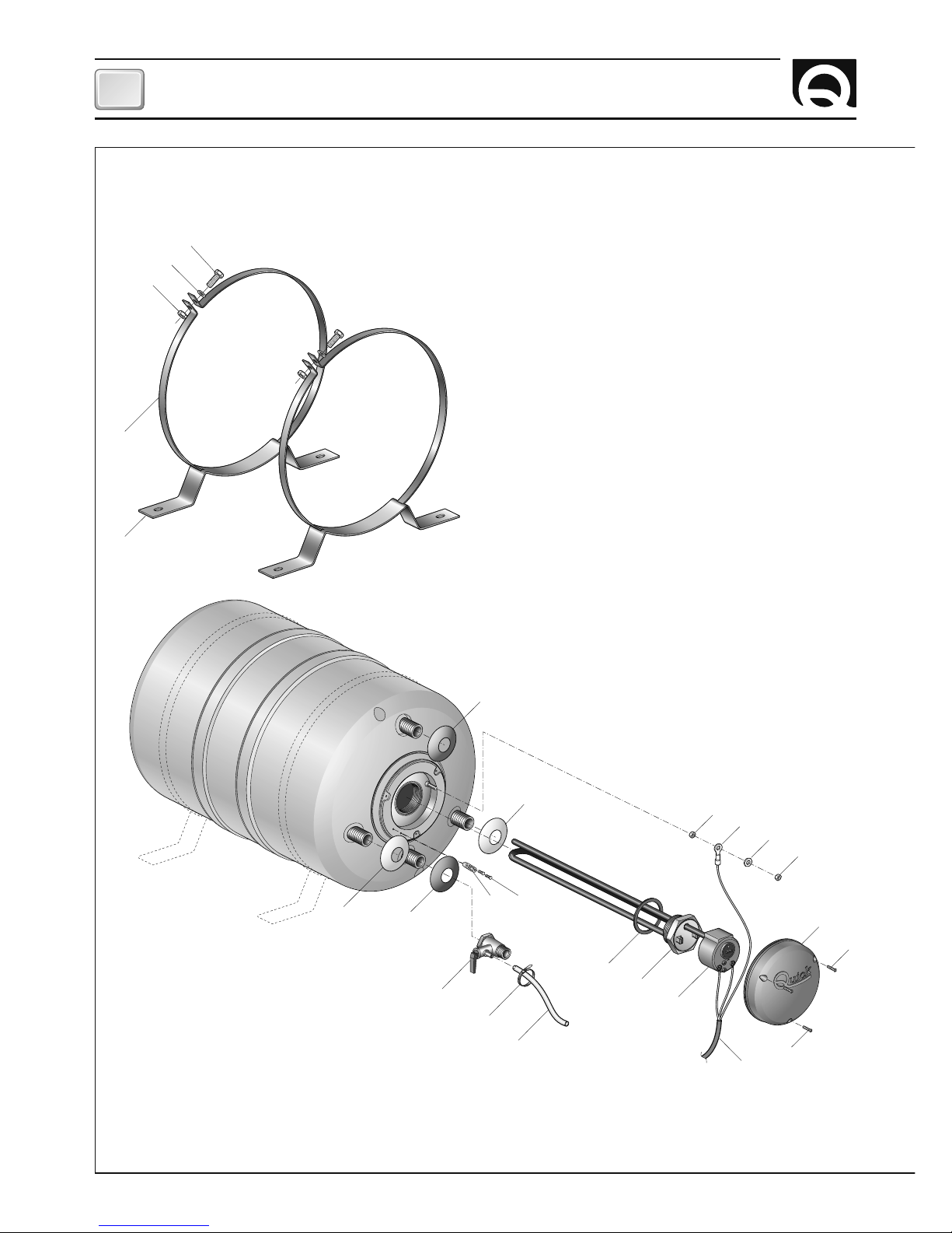
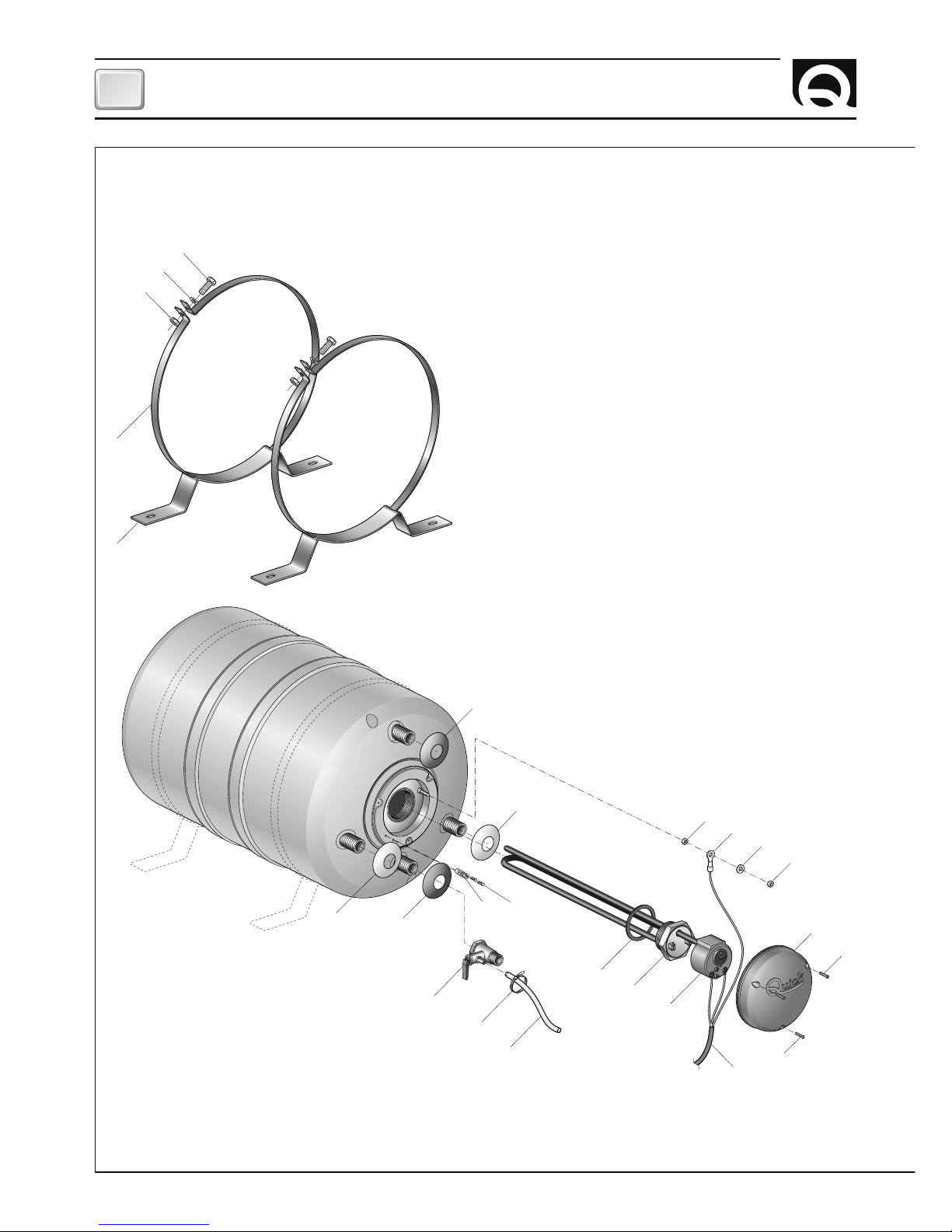
MANUTENZIONE
1
2
2
11
12
13
14
12
3
17
20
19
18
16
4
21 22
10
6
15
15
8
7
9
5
Page 9
9
BOILER B3 15-80 - REV004B
IT
ATTENZIONE: i boiler Quick® sono dotati di bi-ter-
mostato a riarmo manuale che interrompe l’alimentazione elettrica in caso di eccessiva temperatura
dell’acqua.
Nel caso in cui si verifi chi questa condizione procedere come riportato di seguito:
• interrompere l’alimentazione elettrica.
• Smontare il coperchio di protezione (11) per accedere al
termostato (9).
• Premere in pulsante di riarmo del bi-termostato (fi g. 4).
• Montare il coperchio di protezione (11).
• Ripristinare l’alimentazione elettrica.
ATTENZIONE: nel caso in cui la sicurezza di sovra
temperatura intervenga in maniera ripetuta durante
l’utilizzo del boiler contattare un centro assistenza
Quick®.
MANUTENZIONE
Durante la stagione fredda, nel caso in cui il boiler
non sia utilizzato, è consigliabile vuotare il boiler
agendo sulla leva della valvola (4). Questo per evitare danni prodotti dal gelo.
Il dispositivo contro le sovrapressioni deve essere fatto
funzionare regolarmente per rimuovere i depositi di calcare
e per verifi care che non sia bloccato.
Verifi care periodicamente la tenuta dei raccordi dell’impianto idraulico; controllare la chiusura delle viterie di fi ssaggio
e sostituire nel caso in cui siano usurate o corrose.
Verifi care periodicamente l’effi cienza dell’impianto elettrico.
F
MANUTENZIONE
POS. DENOMINAZIONE CODICE
1 Rosetta plastica rossa PECRBLRS0000
2 Rosetta plastica bianca PECRBLBNC000
3 Rosetta plastica blu PECRBLBL0000
4 Valvola di sicurezza e di ritegno MNVALS12S68P
5 Fascetta PBF25100W000
6 Tubo di scarico PVTBGM10NT00
7 A Guarnizione resistenza
da S/N 100.000 PGGRES000000
7 B Guarnizione resistenza
da S/N 200.000 PGRM43500000
8A Resistenza elettrica
1200W 220V EVR12220N000
8B Resistenza elettrica
500W 220V EVR05220N000
8C Resistenza elettrica
1200W 110V EVR12110N000
8D Resistenza elettrica
600W 110V EVR06110N000
9 Bi-termostato EVT15S000000
10 Cavo di alimentazione ECC30150G000
11A Coperchio resistenza B3
boiler 220V PECRB220B300
11B Coperchio resistenza B3
boiler 110V PECRB110B300
12 Dado M4 inox MBD04MXEN000
13 Terminale di terra EJCY04000000
14 Rondella MBR04X000000
15 Vite 2,9 x 19 MBV02919AXCC
16A Fascia metallica
B3 300 MBFPNXB3300
16B Fascia metallica
B3 360 MBFPNXB3360
16C Fascia metallica
B3 400 MBFPNXB3400
17A Staffa metallica
B3 300 MMSTXB300000
17B Staffa metallica
B3 400 MMSTBL400DR1
18 Vite M8 inox MBV0830MXE00
19 Rondella ø 8 MBR08X000000
20 Dado M8 inox MBD08MXEN000
21 Serracavo PPBLB3000000
22 Vite 2,9 x 16 MBV02916AXCC
Page 10

10
TECHNICAL DATA
GB
BOILER B3 15-80 - REV004B
HOW TO IDENTIFY THE WATER HEATER THROUGH THE CODE:
(1)
1 Bar = 100 kPa
(2)
Available on request
(3)
Of empty equipment
(4)
Only for 110 Vac
Quick® reserves the right to introduce changes to the equipment and the contents of this manual without prior notice.
In case of discordance or errors in translation bet ween the translated version and the original text in the Italian language, reference will be made to the Italian or English text.
F
a b c d e
a
a
a
a
a
a b c d e
a
a
a
a
a
1° EXAMPLE : B32005S 2° EXAMPLE : B34012SL
B3 40 12 S LB3 20 05 S -
Product
Name:
[ B3 ] = Water heater
in composite
material
Tank capacity
(liter):
[ 15 ] = 15 liter
[ 20 ] = 20 liter
[ 25 ] = 25 liter
[ 30 ] = 30 liter
[ 40 ] = 40 liter
[ 60 ] = 60 liter
[ 80 ] = 80 liter
Power of electric
element:
[ 00 ] = not installed
[ 05 ] = 500 W
[ 06 ] = 600 W
(4)
[ 12 ] = 1200 W
Heat
exchanger:
[ S ] = present
a
b c d
Voltage of electric
element (if installed):
[ - ] = 220 Vac
[ L ] = 110 vac
e
MODELS
B3 15 B3 20 B3 25 B3 30 B3 40 B3 60 B3 80
TANK CAPACITY
Liters
15 20 25 30 40 60 80
US gallon 3,96 5,28 6,6 7,92 10,56 15,85 21,13
Tank material Stainless steel
Thermal insulator Polyurethane foam
External cladding material Composite
Tank pressure during testing 800 kPa (1)
Maximum working pressure 600 kPa (1)
Electric element voltage rating
(2)
220 Vac ± 10% - (110 Vac ± 10%)
Electric element power
(2)
500 W [Model 05] - 600 W [Model 06]
(4)
- 1200 W [Model 12]
Outputs diameter 1/2”
Weight
(3)
Kg 6,2 7,1 8,1 10,5 12,0 13,4 16,3
Pounds 13.7 15.6 17.8 23.1 26.4 29.5 35.9
Page 11
11
INSTALLATION
GB
BOILER B3 15-80 - REV004B
NAUTIC WATER HEATER
Our long experience operating in the nautical fi eld has given us the means to supply a new series of water
heaters with innovative characteristics compared with other heaters available on the market.
The advantages given by Quick
®
Nautic boilers are:
• high quality of materials ensure the product is both reliable and long lasting.
• Heat exchanger with a large exchanging surface.
• Producing hot water also by means of an electric element, which is provided with an adjustable
and safety thermostat.
• Relief/non return valve that allows discharging of the water heater in case of disuse.
• The installation is easy and practical on a fl at area.
BEFORE USING THE WATER HEATER READ CAREFULLY THIS INSTRUCTION MANUAL.
IF IN DOUBT, PLEASE CONTACT THE NEAREST “QUICK
®
” DEALER.
WARNING: use this water heater in the applications described in this manual. Don’t use the equipment
for any other purpose. Quick® will not be held responsible for damage to equipment and/or personal
injuries caused by a misusage of the equipment.
PACKAGE CONTAINS: water heater - mounting - bolts, nuts and screws (for assembly) - user’s manual - conditions of warranty.
INSTALLATION SITE
The water heater has to be placed in a dry and well-ventilated location. This precaution is required, even
though water heaters are made of sea environment resistant materials, since electrical systems are present
(in models provided). Moreover, if installed in non-ventilated environments, condensation could occur and
could be mistaken for a leak.
INSTALLATION
• Put mounting (17) on the tank (1) using studs and nuts provided (18, 19, 20).
• Fix water heater on fl at surface or inclined plane or wall, as shown in fi g. 1, using proper mountings for the
weight of the water heater and for the type of installation site in the boat.
WARNING: the weight of water heater/unit in the technical data refers to the empty unit. In order to
have the gross weight add to the empty weight, the water amount. (1 liter of water will almost weigh 1
Kg. / 2,2 lb).
• Carry out the hydraulic connections, relating to the input and output of tap water and from the engine
cooling to the heat exchanger, as shown in fi g. 2. Keep the connections between engine cooling system and
heat exchanger as short as possible.
WARNING: the overpressure release pipe must be positioned sloping evenly downwards in a location
protected from the formation of ice.
WARNING: water might drip from the overpressure release pipe of the device, and this pipe must be
left open to the atmosphere.
WARNING: when fi ttings are used on water outlets, use Loctite 243, 577 or Tefl on on the threads in order to ensure tightness. Make sure that there is no water leakage.
Page 12

12
GB
BOILER B3 15-80 - REV004B
CONNECTION DIAGRAM
LIVE NEUTRAL EARTH
SWITCH
FUSE
BROWN
BLUE
YELLOW / GREEN
FIG.3
FIG.1
FIG.2
ENGINE
COOLING LIQUID
HOT TAP
WATER OUTPUT
COLD TAP
WATER INPUT
TAP WATER TANK
AUTOCLAVE
COLD WATER
HOT WATER
EXPANSION TANK
FIG.4
NEUTRAL
AC NETWORK
LIVE
AC NETWORK
THERMOSTAT
KNOB
RESET BUTTON
Page 13
13
GB
BOILER B3 15-80 - REV004B
WARNING: follow the instructions of the boat engine manufacturer on how to connect engine cooling
liquid to the heat exchanger.
• Fit the stub pipe (6) to the relief valve (4) using the hose clamp (5).
Fit the pipe so as to allow any possible water leak not to cause damage to parts of the boat.
• Open up hot water taps of the washbasins and start the water pump. This allows water to fi ll the water
heater and force air out of the water heater and pipes. Close taps as soon as air free water comes
out of the taps.
• Check that there are no leaks on pipe joints.
UNIT POWER SUPPLY (In models provided)
The unit is provided with power supply cable for AC current. See fi g. 3 for the connection. Make sure the water
heater operating voltage is the same as that provided by AC network.
A double pole switch has to be included on the electric installation in order to turn on and off the unit, as well
as a fuse of suitable rating. The insulation between connection contacts of the AC network must be at least 3
mm. The connections to AC network must be done following the National Specifi cations on electrical installa-
tions.
WARNING: before carrying out the connection make sure the cables are not live.
WARNING: in case the power supply cable is damaged, ensure it is replaced by a Quick service center.
In order to avoid accidents, the equipment has to be opened by authorized personnel only. If opened by
an unauthorized person, the warranty is considered void.
WARNING: don’t operate the electric element if the tank is not fi lled with water. It may cause a permanent damage to the electric element.
THERMOSTAT ADJUSTMENT (in models provided)
The standard temperature value of the thermostat is 60°C.If you wish to change it, follow the instructions
below:
• shut down power supply.
• Remove the protection cover (11) in order to reach the thermostat (9).
• Adjust the thermostat knob with a screwdriver (fi g. 4) and turn it to the required temperature.
• Replace the protection cover (11).
• Switch on power supply.
The thermostat sets the water temperature only with electric element operation.
USAGE - WARNING
F
Page 14
14
GB
BOILER B3 15-80 - REV004B
MAINTENANCE
1
2
2
11
12
13
14
12
3
17
20
19
18
16
4
21 22
10
6
15
15
8
7
9
5
Page 15
15
GB
BOILER B3 15-80 - REV004B
WARNING: Quick® nautic water heaters are provided
with a double thermostat with manual reset that
shuts down power supply in case of an excessive
water temperature.
If it happens, follow the instructions below:
• shut down power supply.
• Remove the protection cover (11) in order to reach
the thermostat (9).
• Push the reset button on the double thermostat (fi g. 4).
• Replace on the protection cover (11).
• Switch on power supply.
WARNING: if the high temperature safety system
switches on repeatedly, call Quick
®
service center.
MAINTENANCE
During wintertime, when the water heater is not
in use it should be drained using the lever of the
valve (4). This is to avoid serious damage caused
by freezing.
The overpressure release device must be activated regularly to remove calcium deposits and to ensure that it is not
blocked.
Periodically check the joints of the water pipe installation;
check the tightness of the securing screws and replace
them in case they are worn or corroded.
Also periodically check the electrical system working order.
MAINTENANCE
F
POS. DESCRIPTION CODE
1 Red plastic washer PECRBLRS0000
2 White plastic washer PECRBLBNC000
3 Blue plastic washer PECRBLBL0000
4 Relief/non return valve MNVALS12S68P
5 Hose clamp PBF25100W000
6 Discharge pipe PVTBGM10NT00
7 A Element gasket
from S/N 100.000 PGGRES000000
7 B Element gasket
from S/N 200.000 PGRM43500000
8A Electric element
1200W 220V EVR12220N000
8B Electric element
500W 220V EVR05220N000
8C Electric element
1200W 110V EVR12110N000
8D Electric element
600W 110V EVR06110N000
9 Bi-Thermostat EVT15S000000
10 Power supply cable ECC30150G000
11A B3 resistor cover 220V PECRB220B300
11B B3 resistor cover 110V PECRB110B300
12 Nut M4 stainless steel MBD04MXEN000
13 Ground cable terminal EJCY04000000
14 Washer MBR04X000000
15 Screw 2,9 x 19 MBV02919AXCC
16A Tank mounting
B3 300 MBFPNXB3300
16B Tank mounting
B3 360 MBFPNXB3360
16C Tank mounting
B3 400 MBFPNXB3400
17A Metal bracket
B3 300 MMSTXB300000
17B Metal bracket
B3 400 MMSTBL400DR1
18 Screw M8 stainless steel MBV0830MXE00
19 Washer Ø 8 stainless steel MBR08X000000
20 Nut M8 stainless steel MBD08MXEN000
21 Cable clamp PPBLB3000000
22 Screw 2,9 x 16 MBV02916AXCC
Page 16
16
CARACTERISTIQUES TECHNIQUES
FR
BOILER B3 15-80 - REV004B
COM MENT LI RE LE CO DE DE CHAUFFE-EAU:
La société Quick® se réserve le droit d'apporter les modifi cations nécessaires aux caractéristiques tech niques d e l'ap pareil et a u con tenu de ce li vret sans avis préa lable.
En cas de discordances ou d’erreurs éventuelles entre la traduction et le texte original en italien, se référer au texte italien ou anglais.
F
a b c d e
a
a
a
a
a
a b c d e
a
a
a
a
a
1° EXAMPLE : B32005S 2° EXAMPLE : B34012SL
B3 40 12 S LB3 20 05 S -
Nom du
produit:
[ B3 ] = Chauffe-eau en
polypropylène
Capacité du
réservoir en litres
:
[ 15 ] = 15 litres
[ 20 ] = 20 litres
[ 25 ] = 25 litres
[ 30 ] = 30 litres
[ 40 ] = 40 litres
[ 60 ] = 60 litres
[ 80 ] = 80 litres
Puissance de la
résistance électrique
:
[ 00 ] = non installée
[ 05 ] = 500 W
[ 06 ] = 600 W
(4)
[ 12 ] = 1200 W
Echangeur
de chaleur:
[ S ] = présent
a
b c d
Tension de la résistance
électrique (si installée)
:
[ - ] = 220 Vac
[ L ] = 110 vac
e
(1)
1 Bar = 100 kPa
(2)
Disponible sur demande
(3)
Appareil à vide
(4)
Seul pour 110 Vac
MODÈLES
B3 15 B3 20 B3 25 B3 30 B3 40 B3 60 B3 80
CAPACITÉ DU
RESERVOIR
Litre
15 20 25 30 40 60 80
Gallon U.S 3,96 5,28 6,6 7,92 10,56 15,85 21,13
Matériel du réservoir Acier inox
Protection interne Polyuréthane expansé rigide à cellules fermées
Revêtement externe Polypropilène copolymère
Pression du réservoir pendant les essais 800 kPa (1)
Pression max. de travail 600 kPa (1)
Tension de l’élément chauffant
(2)
220 Vac ± 10% - (110 Vac ± 10%)
Puissance de l’élément chauffant
(2)
500 W [v 05] - 600 W [Modèle 06]
(4)
- 1200 W [Modèle 12]
Diamétre du raccord 1/2”
Poids
(3)
Kg 6,2 7,1 8,1 10,5 12,0 13,4 16,3
Livres 13.7 15.6 17.8 23.1 26.4 29.5 35.9
Page 17

17
INSTALLATION
FR
BOILER B3 15-80 - REV004B
CHAUFFE-EAU QUICK
Notre longue expérience du secteur de la navigation nous a permis de développer une série de chauffe-eau
avec des caractéristiques d'avant-garde par rapport aux articles standards que l'on trouve sur le marché.
Les avantages que les chauffe-eau nautiques Quick
®
offrent sont les suivants:
• qualité élevée des matériaux garantissant longue durée et résistance.
• Echangeur de chaleur équipé d'une grande surface d'échange.
• Possibilité de produire de l'eau chaude même avec la résistance électrique, complète de thermostat de sé-
curité réglable (dans les modèles équipés).
• Clapet de sûreté et de retenue permettant de déverser l'eau du chauffe-eau en cas d'inutilisation.
• Installation pratique à plat.
AVANT DE SE SERVIR DU CHAUFFE-EAU, LIRE ATTENTIVEMENT CE MODE D'EMPLOI.
EN CAS DE DOUTES, S'ADRESSER AU REVENDEUR QUICK
®
.
ATTENTION: ne se servir du chauffe-eau que pour les applications décrites dans ce mode d'emploi. Ne
pas se servir de cet appareil pour d'autres types d'opérations. Quick® ne se rend pas responsable des
dommages directs ou indirects causés par un mauvais emploi de l'appareil.
L'EMBALLAGE COMPREND: chauffe-eau - bandes pour la fi xation à plat ou contre paroi - vis et éléments de
montage divers (pour l'assemblage) - mode d'emploi - conditions de garantie.
LIEU D'INSTALLATION
Le chauffe-eau doit être installé dans un endroit sec et bien aéré. Il est nécessaire de prendre cette précaution
même si le chauffe-eau est construit avec des matériaux résistant à l'habitat marin vu la présence de dispositifs électriques (dans les modèles équipés).
Installer le chauffe-eau dans un endroit qui n'est pas aéré pourrait causer des phénomènes de condensation;
l'eau de condensation, alors, peut être prise pour une fuite qui, en réalité, n'existe pas.
INSTALLATION
• Appliquer les bandes (17) au réservoir (1) en se servant des vis et boulons fournis (18, 19, 20).
• Fixer le chauffe-eau à plat,contre une paroi ou sur une surface inclinée comme indiqué dans la fi gure 1 à
l’aide de supports appropriés au poids du chauffe-eau et au type de surface ou de paroi à disposition pour
l’installation.
ATTENTION: le poids du chauffe-eau indiqué dans les caractéristiques techniques est à vide. Pour le
poids du chauffe-eau rempli d'eau, ajouter au poids à vide le poids de la masse d'eau contenue (1 litre
d'eau correspond à 1 Kg. / 2,2 lb).
• Faire les raccords hydrauliques relatifs à l'entrée et à la sortie de l'eau sanitaire et au circuit de refroidisse-
ment du moteur à l'échangeur de chaleur comme d'après la fi gure 2. La connexion entre le circuit de refroidissement du moteur et l'échangeur du chauffe-eau doit être la plus courte possible.
ATTENTION: le tuyau d’évacuation de surpression doit étre placé en pente continue vers le bas et dans
un lieu protégé contre la formation de glace.
ATTENTION: l’eau peut couler du tuyau d’évacuation du dispositif contre les surpressions et ce tuyau
doit être laissé à l’atmosphère.
ATTENTION: dans le cas où l’on monte des raccords sur les sorties, appliquer de la Loctite 243, 577 ou
du Tefl on sur les fi lets. Vérifi er l’étanchéité.
Page 18

18
FR
BOILER B3 15-80 - REV004B
SCHEMA DE CABLAGE
PHASE NEUTRE TERRE
INTERRUPTEUR
FUSIBILE
MARRON
BLUE
JAUNE / VERT
FIG.3
FIG.1
FIG.2
LIQUIDE
POUR REFROIDIR
LE MOTEUR
SORTIE DE L'EAU
SANITAIRE CHAUDE
ENTREE DE
L'EAU SANITAIRE
FROIDE
RESERVOIR DE
L'EAU SANITAIRE
AUTOCLAVE
EAU FROIDE
EAU CHAUDE
VASE D'EXPANSION
FIG.4
NEUTRE
SECTEUR
EN C.A.
PHASE SECTEUR
EN C.A.
POIGNEE POUR
REGLER LA
TEMPÉRATURE
BOUTONPOUSSOIR DE
RÉENCLENCHEMENT
Page 19

19
FR
BOILER B3 15-80 - REV004B
ATTENTION: suivre les instructions du fabricant du moteur pour ce qui concerne le prélèvement du
liquide de refroidissement à envoyer à l'échangeur du chauffe-eau.
• Raccorder le tuyau de décharge (6) à la soupape (4) et le serrer avec le collier de serrage (5).
Le positionner de manière à éviter que l'eau n'endommage d'autres objets en cas de débordement.
• Ouvrir les robinets de l'eau chaude des lavabots et mettre l'autoclave en marche.
De cette manière là, l'air se trouvant à l'intérieur du chauffe-eau et dans les conduites peut
s'échapper. Fermer les robinets dès que seule l'eau commence à sortir.
• Vérifi er qu'il n'y a pas de fuites dans les raccords.
ALIMENTATION ELECTRIQUE DE L'APPAREIL (dans les modèles équipés)
L'appareil est déjà équipé du câble d'alimentation électrique pour le secteur en C.A. Pour les connexions au
secteur en C.A., voir fi gure 3. Avant d'alimenter le chauffe-eau, contrôler si la tension de fonctionnement correspond bien à celle fournie par le secteur en C.A.
Un interrupteur à deux pôles doit être installé dans l'appareillage électrique pour allumer et éteindre l'appareil
ainsi qu'un fusible approprié à l'absorption. L'isolation entre les contacts des connexions sur le secteur en C.A.
doit être de 3 mm minimum. Les connexions au secteur en C.A. doivent être réalisées en conformité avec les
normes nationales concernant les installations électriques.
ATTENTION: avant d'effectuer la connexion, vérifi er que les câbles ne sont pas alimentés en électricité.
ATTENTION: si le câble d'alimentation est endommagé, le faire remplacer par un centre de service
après-vente Quick. Afi n d'éviter des accidents, l'appareil ne doit être ouvert que par le personnel autorisé. Si l'appareil est ouvert par du personnel non autorisé, la garantie est annulée.
ATTENTION: ne jamais allumer la résistance électrique si le chauffe-eau n'est pas plein d'eau pour ne
pas causer un dommage irréversible de l'élément chauffant.
REGLAGE DU THERMOSTAT (dans les modèles équipés)
La valeur de température établie sur le thermostat par l'usine est de 60°C. Si l'on désire modifi er cette valeur,
suivre les instructions ci-dessous:
• interrompre l'alimentation électrique.
• Enlever le couvercle (11) pour accéder au thermostat (9).
• Agir sur la poignée du thermostat (fi gure 4) à l'aide d'un tournevis et établir la valeur de température désirée.
• Remettre le couvercle (11).
• Rétablir l'alimentation électrique.
Le thermostat règle la température de l'eau exclusivement lors du fonctionnement avec la résistance
électrique.
UTILISATION - AVVERTISSEMENTES IMPORTANTS
F
Page 20

20
FR
BOILER B3 15-80 - REV004B
ENTRETIEN
1
2
2
11
12
13
14
12
3
17
20
19
18
16
4
21 22
10
6
15
15
8
7
9
5
Page 21

21
FR
BOILER B3 15-80 - REV004B
F
ATTENTION: les chauffe-eau Quick® sont équipés
de bi-thermostat à réenclenchement manuel qui
interrompt l'alimentation électrique en cas de température excessive de l'eau.
Au cas où il se vérifi erait cette condition, suivre les
instructions ci-dessous:
• interrompre l'alimentation électrique.
• Enlever le couvercle (11) pour accéder au thermo stat (9).
• Appuyer sur un bouton-poussoir de réenclenche ment du bi-thermostat (fi gure 4).
• Remettre le couvercle (11).
• Remettre l'alimentation électrique.
ATTENTION: si le dispositif de sécurité contre une
température excessive se déclenche souvent durant
l'utilisation du chauffe-eau, s'adresser à un centre
de service après-vente Quick
®
.
ENTRETIEN
Durant l'hiver, si le chauffe-eau n'est pas utilisé,
il est conseillé de vider le chauffe-eau à l'aide du
levier de soupape (4) afi n d'éviter des dommages
produits par le gel.
Il faut faire fonctionner régulièrement le dispositif contre
les surpressions afi n d’enlever les dépôts de calcaire et
pour vérifi er s’il n’est pas bloqué.
Vérifier périodiquement l'étanchéité des raccords dans
l'installation hydraulique. Contrôler si les vis et boulons de
fi xation sont bien serrés et les remplacer s'ils sont usés ou
corrodés.
Vérifi er périodiquement si l'installation électrique est en
bon état de fonctionnement.
F
ENTRETIEN
POS. DENOMINATION CODE
1 Rondelle en matière
plastique rouge PECRBLRS0000
2 Rondelle en matière
plastique blanche PECRBLBNC000
3 Rondelle en matière
plastique bleue PECRBLBL0000
4 Clapet de sûreté et de retenue MNVALS12S68P
5 Collier de serrage PBF25100W000
6 De purge tube PVTBGM10NT00
7 A Garniture de la résistance
de S/N 100.000 PGGRES000000
7 B Garniture de la résistance
de S/N 200.000 PGRM43500000
8A Résistance électrique
1200W 220V EVR12220N000
8B Résistance électrique
500W 220V EVR05220N000
8C Résistance électrique
1200W 110V EVR12110N000
8D Résistance électrique
600W 110V EVR06110N000
9 Bi-thermostat EVT15S000000
10 Fiche d'alimentation ECC30150G000
11A Couvercle résistance
chauffeau B3 220V PECRB220B300
11B Couvercle résistance
chauffeau B3 110V PECRB110B300
12 Ecrou M4 inox MBD04MXEN000
13 Borne de terre EJCY04000000
14 Rondelle MBR04X000000
15 Vis 2,9 x 19 MBV02919AXCC
16A Bande métallique
B3 300 MBFPNXB3300
16B Bande métallique
B3 360 MBFPNXB3360
16C Bande métallique
B3 400 MBFPNXB3400
17A Etrier métallique
B3 300 MMSTXB300000
17B Etrier métallique
B3 400 MMSTBL400DR1
18 Vis M8 inox MBV0830MXE00
19 Rondelle Ø8 inox MBR08X000000
20 Ecrou M8 inox MBD08MXEN000
21 Serre-cable PPBLB3000000
22 Vis 2,9 x 16 MBV02916AXCC
Page 22

22
TECHNISCHE EIGENSCHAFTEN
DE
BOILER B3 15-80 - REV004B
LESEN DES BOILERCODES:
Quick® behält sich das Recht auf Änderungen der technischen Eigenschaften des Geräts und des Inhalts dieses Handbuchs ohne Vorankündigung vor.
Bei Fehl ern oder e ventue llen Uns timmig keiten z wische n der Übe rsetzu ng und de m Ausga ngstex t ist der A usgang stext in I talie nisch oder Englisch maßgeblich.
F
a b c d e
a
a
a
a
a
a b c d e
a
a
a
a
a
1° BEISPIEL : B32005S 2° BEISPIEL : B34012SL
B3 40 12 S LB3 20 05 S -
Produktbezeichnung:
[ B3 ] = Boiler aus
Polypropylen
Fassungsvermögen
des Tanks in Litern:
[ 15 ] = 15 litern
[ 20 ] = 20 litern
[ 25 ] = 25 litern
[ 30 ] = 30 litern
[ 40 ] = 40 litern
[ 60 ] = 60 litern
[ 80 ] = 80 litern
Leistung des elektrschen
Widerstandes:
[ 00 ] = Nicht installiert
[ 05 ] = 500 W
[ 06 ] = 600 W
(4)
[ 12 ] = 1200 W
Wärmeaustauscher:
[ S ] = Vorhanden
a
b c d
Spannung elektrische
Widerstand (falls installiert):
[ - ] = 220 Vac
[ L ] = 110 Vac
e
(1)
1 Bar = 100 kPa
(2)
Verfügbar auf Wunsch
(3)
Bei leerem Gerät
(4)
Nur für 110 Vac
MODELLE
B3 15 B3 20 B3 25 B3 30 B3 40 B3 60 B3 80
FASSUNGSVERMÖGEN
TANK
Liter
15 20 25 30 40 60 80
US dry gallon 3,96 5,28 6,6 7,92 10,56 15,85 21,13
Material Tank Edelstahl
Innenschutz Harter Polyurethan-Schaumstoff mit geschlossenen Zellen
Material für Außenverkleidung Kopolymer-Polypropylen
Tankdruck während der Abnahmeprüfung 800 kPa (1)
Maximale Arbeitslast 600 kPa (1)
Spannung Heizkörper
(2)
220 Vac ± 10% - (110 Vac ± 10%)
Leistung Heizkörper
(2)
500 W [Modell 05] - 600 W [Modell 06]
(4)
- 1200 W [Modell 12]
Diamétre du raccord 1/2”
Gewicht
(3)
Kg 6,2 7,1 8,1 10,5 12,0 13,4 16,3
Lbs 13.7 15.6 17.8 23.1 26.4 29.5 35.9
Page 23

23
INSTALLATION
DE
BOILER B3 15-80 - REV004B
BOILER QUICK
®
Die langjährigen, auf dem Nautiksektor entwickelten Erfahrungswerte haben dazu beigetragen, dass uns die
Entwicklung einer Boilerserie gelungen ist, die im Hinblick auf den Marktstandard innovative Eigenschaften
aufweist. Die Quick
®
-Nautikboiler bieten die folgenden Vorteile:
• erhöhte Materialqualität zur Gewährleistung einer langen Lebensdauer und einer hohen Widerstandsfähigkeit.
• Wärmeaustauscher aus-gerüstet mit beträchtlicher Austauschoberfl äche (bei den entsprechenden).
• Möglichkeit der Heißwassererzeugung auch mit elektrischem Heizwiderstand, komplett mit regulierbarem
Sicherheitsthermostat.
• Flansch zur Inspektion des Boilerinneren.
• Schutz vor natürlicher Elektrolyse durch Magnesiumanode.
• Sicherheits- und Rückschlagventil zum Ablass des Wassers aus dem Boiler im Falle von Nichtbenutzung.
• Praktische Installierung an Wand oder Boden.
VOR GEBRAUCH DES BOILERS IST DIE VORLIEGENDE BEDIENUNGSANLEITUNG AUFMERKSAM
DURCHZULESEN. IM ZWEIFELSFALL DEN QUICK
®
-FACHHÄNDLER KONTAKTIEREN.
ACHTUNG: den Boiler nur für die in diesem Handbuch beschriebenen Verwendungsmöglichkeiten ein-
setzen. Dieses Gerät nicht für andere Zwecke verwenden. Quick
®
übernimmt keinerlei Verantwortung für
direkte oder indirekte Schäden, die auf einen ungeeigneten Gebrauch des Gerätes zurückzuführen sind.
DIE VERPACKUNG ENTHÄLT: Boiler - Bänder für die Befestigung an Boden oder Wand - Verschiedene Schrauben und Kleinteile (für die Montage) - Bedienungsanleitung - Garantiebedingungen.
MONTAGEORT
Der Boiler muss an einem trockenen und gut belüfteten Ort montiert werden. Obwohl der Boiler aus seewasserfesten Materialien besteht, ist diese Vorsichtsmaßnahme aufgrund der vorhandenen elektrischen
Vorrichtungen erforderlich (bei den entsprechenden). Die Installierung in nicht belüfteter Umgebungen könnte
zur Kondenswasserbildung führen. Das Kondens Wasser könnte fälschlicherweise für eine Leckage gehalten
werden, die in Wirklichkeit nicht vorliegt.
INSTALLIERUNG
• Die Bänder (17) am Tank (1) anbringen; hierzu die als Zubehör mitgelieferten Schrauben (18, 19, 20) verwen-
den.
• Den Boiler, wie in der Abbildung 1 dargestellt, an der Wand, am Boden oder in geneigter Stellung befestigen.
Hierzu sind Halter zu verwenden, die sich sowohl für das Gewicht des Boilers als auch für den entsprechend
zur Installierung vorliegenden Boden- oder Wandtyp eignen.
ACHTUNG: das bei den technischen Eigenschaften angegebene Gewicht des Boilers gibt das
Leerge-wicht an. Um das Gewicht bei voller Belastung zu erhalten, muss man das Leergewicht zu dem
Gewicht der enthaltenen Wassermasse addieren (1 Liter Wasser entspricht ca. 1 Kg. / 2,2 lb).
• Die hydraulischen Anschlüsse für den Ein- und Auslauf des Sanitärwassers und am Kühlkreislauf des Motors
für den Wärmeaustauscher, wie in Abbildung 2 dargestellt, durchführen. Den Anschluss zwischen dem Kühlkreislauf des Motors und dem Wärmeaustauscher des Motors so kurz wie möglich gestalten.
ACHTUNG: der Ablasschlauch der Vorrichtung gegen Úberdruck muss beim verlegen kontinuierlich nach
unten geführt und an einem Ort positioniert werden, an dem er vor dem einfrieren geschützt ist.
ACHTUNG: aus dem Ablasschlauch von der Vorrichtung gegen Úberdruck kann Wasser tropfen. Der
Schlauch muss deshalb offen gelassen und im freien positioniert werden.
ACHTUNG: um Anschlusse zu verbinden bitte Loctite 243, 577 oder Tefl on benutzen.
Stellen Sie sicher dass keine Wasserverluste vorhanden sind
Page 24

24
DE
BOILER B3 15-80 - REV004B
ANSCHLUSSPLAN
PHASE NULLEITER ERDE
SCHALTER
SICHERUNG
BRAUN
BLAU
GELG / GRÜN
ABB. 3
ABB. 1
ABB. 2
KÜHLFLÜSSIGKEIT
MOTOR
AUSLAUF
WARMES
SANITÄRWASSER
EINLAUF KALTES
SANITÄRWASSER
SANITÄRWASSERTANK
DRUCKKESSEL
KALTWASSER
WARMWASSER
AUSDEHNUNGSGEFÄSS
ABB. 4
NULLEITER
WECHSEL-
STROMNETZ
PHASE WECHSELSTROMNETZ
GRIFF ZUR
TEMPERATUR-
EINSTELLUNG
RÜCKSTELLTASTE
Page 25

25
DE
BOILER B3 15-80 - REV004B
ACHTUNG: für die Entnahme der zum Austauscher geleiteten Kühlfl üssigkeit sind die Anweisungen des
Motorherstellers zu befolgen..
• Die Ablassleitung (6) des Ventils (4) uber einen Kabelbinder (5) befestigen, so positionieren dass bei einem
eventuellen Wasseraustritt keine anderen Gegenstände beschädigt werden.
• Die Warmwasserhähne der Waschbecken aufdrehen und den Druckkessel anlassen. Auf diese Weise wird die
im Boilerinneren sowie in den Leitungen vorhandene Luft abgelassen. Die Hähne wieder schließen, sobald
ein ausschließlicher Wasseraustritt zu verzeichnen ist.
• Stellen Sie sicher, dass keine Leckagen an den Anschlussstücken vorliegen.
STROMVERSORGUNG DES GERÄTES (bei den damit ausgerüsteten Modellen)
Das Gerät ist bereits mit einem Speisekabel für das Wechselstromnetz ausgerüstet. Für den Anschluss an das
Wechselstromnetz, siehe Abbildung 3. Vor der Speisung des Boilers sicherstellen, dass dessen Betriebsspannung derjenigen des Wechselstromnetzes entspricht.
An der elektrischen Anlage muss ein zweipoliger Schalter für das Ein- und Ausschalten des Gerätes sowie eine
für die Aufnahme geeignete Sicherung installiert werden. Die Isolierung zwischen den Kontakten des Wechselstromnetzes muss mindestens 3 mm betragen. Die Anschlüsse an das Wechselstromnetz müssen in Übereinstimmung mit den nationalen Vorschriften für elektrische Anlagen ausgeführt werden.
ACHTUNG: vor dem Anschluss muss sichergestellt werden, dass die Kabel nicht mit Strom versorgt
werden.
ACHTUNG: sollte das Speisekabel beschädigt sein, so muss dieses durch den Quick®-Kundendienst-
service ersetzt werden. Das Gerät darf nur von Fachpersonal geöffnet werden, um das Ausbrechen
von Bränden zu vermeiden. Das Öffnen des Gerätes durch unbefgtes Personal führt zum Verfall der
Garantie.
ACHTUNG: schalten Sie den elektrischen Widerstand keinesfalls ein, wenn der Boiler kein Wasser enthält; dies führt zu irreversiblen Schäden am Heizelement.
EINSTELLUNG DES THERMOSTATS (bei den damit ausgerüsteten Modellen)
Der vom Werk am Thermostat eingestellte Temperaturwert beträgt 60°C. Falls man diesen Wert ändern möchte, so ist das nachfolgend beschriebene Verfahren zu befolgen:
• die Stromversorgung unterbrechen.
• Den Schutzdeckel (11) abnehmen, um an der Thermostat gelangen zu können (9).
• Mit einem Schraubenzieher auf den Griff des Thermostats (Abb. 4) einwirken und den maximalen Tempera-
turwert einstellen.
• Den Schutzdeckel (11) wieder anbringen.
• Die Stromversorgung wieder einschalten.
Der Mischer reguliert die Warmwassertemperatur sowohl beim Betrieb mit elektrischem Widerstand
als auch mit Wärmeaustauscher.
GEBRAUCH - WICHTIGE HINWEISE
F
Page 26

26
DE
BOILER B3 15-80 - REV004B
WARTUNG
1
2
2
11
12
13
14
12
3
17
20
19
18
16
4
21 22
10
6
15
15
8
7
9
5
Page 27

27
DE
BOILER B3 15-80 - REV004B
ACHTUNG: die Quick®-Boiler sind mit Doppel-Ther-
mostaten mit manueller Rückstellung ausgestattet,
durch die die Stromversorgung im Fall einer übermäßig hohen Wassertempertatur unterbrochen wird.
Sollte dieser Fall eintreten, muss wie folgt vorgegangen werden:
• die Stromversorgung unterbrechen.
• Den Schutzdeckel (11) abnehmen, um an der Ther mostat gelangen zu können (9).
• Die Rückstelltaste des Doppel-Thermostats (Abb. 4)
drücken.
• Den Schutzdeckel (11) wieder anbringen.
• Die Stromversorgung wieder einschalten.
ACHTUNG: sollte die Übertemperatur-Sicherheitsvorrichtung während der Boilerbenutzung wiederholt ausgelöst werden, so muss man sich mit dem
Quick
®
-Kundendienstservice in Verbindung setzen.
WARTUNG
Falls der Boiler während kalter Jahreszeiten nicht
benutzt werden sollte, empfi ehlt es sich, den Boiler
zu entleeren. Hierzu auf den Hebel des Ventils (4)
einwirken. Auf diese Weise werden Frostschäden
vermieden.
Die Vorrichtung gegen überdruck muss regelmäßig eingeschaltet werden, um die kalkablagerungen zu beseitigen
und sicherzustellen, dass die Vorrichtung nicht blockiert ist.
Die Dichtigkeit der Anschlussstücke der Hydraulikanlage
überprüfen; die Aufspannung der Befestigungsschrauben
kontrollieren und diese im Fall von Abnutzung oder Korrosion ersetzen.
Regelmäßig die Leistungsfähigkeit der elektrischen Anlage
überprüfen.
F
WARTUNG
POS. BEZEICHNUNG CODE
1 Rote Plastikscheibe PECRBLRS0000
2 Weiße Plastikscheibe PECRBLBNC000
3 Blaue Plastikscheibe PECRBLBL0000
4 Sicherheits- und Rückschlagventil MNVALS12S68P
5 Schelle PBF25100W000
6 Leitung PVTBGM10NT00
7 A Dichtung Widerstand
von S/N 100.000 PGGRES000000
7 B Dichtung Widerstand
von S/N 200.000 PGRM43500000
8A Elektrischer Widerstand
1200W 220V EVR12220N000
8B Elektrischer Widerstand
500W 220V EVR05220N000
8C Elektrischer Widerstand
1200W 110V EVR12110N000
8D Elektrischer Widerstand
600W 110V EVR06110N000
9 Doppel-Thermostat EVT15S000000
10 Speisekabel ECC30150G000
11A Abdeckung Widerstand
Boiler B3 220V PECRB220B300
11B Abdeckung Widerstand
Boiler B3 110V PECRB110B300
12 Mutter M4 Edelstahl MBD04MXEN000
13 Erdklemme E JCY04000000
14 Paßscheib MBR04X000000
15 Scraub 2,9 x 19 MBV02919AXCC
16A Metallband
B3 300 MBFPNXB3300
16B Metallband
B3 360 MBFPNXB3360
16C Metallband
B3 400 MBFPNXB3400
17A Metallbügel
B3 300 MMSTXB300000
17B Metallbügel
B3 400 MMSTBL400DR1
18 Schrauben M8 Edelstahl MBV0830MXE00
19 Paßscheib Ø8 Edelstahl MBR08X000000
20 Mutter M8 Edelstahl MBD08MXEN000
21 Kabelschelle PPBLB3000000
22 Scraub 2,9 x 16 MBV02916AXCC
Page 28

28
CARACTERÍSTICAS TÉCNICAS
ES
BOILER B3 15-80 - REV004B
CÓMO SE LEE EL CÓDI GO DEL CALENTADOR:
Quick® se reserva el derecho de aportar modifi caciones en las características técnicas del aparato y en el contenido de este manual sin obligación de avisa r previamente.
En caso de discordancias o eventuales errores entre el texto traducido y el texto original en italiano, remitirse al texto en italiano o en inglés.
F
a b c d e
a
a
a
a
a
a b c d e
a
a
a
a
a
1° EJEMPLO : B32005S 2° EJEMPLO : B34012SL
B3 40 12 SLB3 20 05 S -
Nombre
del producto:
[ B3 ] = Calentador en
polipropileno
Capacidad en
litros del tangue:
[ 15 ] = 15 litros
[ 20 ] = 20 litros
[ 25 ] = 25 litros
[ 30 ] = 30 litros
[ 40 ] = 40 litros
[ 60 ] = 60 litros
[ 80 ] = 80 litros
Potencia de la
resistencia eléctrica:
[ 00 ] = no instalada
[ 05 ] = 500 W
[ 06 ] = 600 W
(4)
[ 12 ] = 1200 W
Intercambiador
de calor:
[ S ] = presente
a
b
c d
e
Tensión resistencia eléctrica
(si ésta instalada):
[ - ] = 220 Vac
[ L ] = 110 vac
(1)
1 Bar = 100 kPa
(2)
Disponible bajo petición
(3)
En vacío del aparado
(4)
Sólo para 110 Vac
MODELOS
B3 15 B3 20 B3 25 B3 30 B3 40 B3 60 B3 80
CAPACIDAD TANGUE
Litros
15 20 25 30 40 60 80
USA galón 3,96 5,28 6,6 7,92 10,56 15,85 21,13
Material tangue Acero inox
Protección interna Poliuretano celular rígido con células cerradas
Material de revestimiento externo Polipropileno copolímero
Presión del tangue durante las pruebas 800 kPa (1)
Presión máxima de servicio 600 kPa (1)
Tensión elemento calentador
(2)
220 Vac ± 10% - (110 Vac ± 10%)
Potencia elemento calentador
(2)
500 W [Modelo 05] - 600 W [Modelo 06]
(4)
- 1200 W [Modelo 12]
Diámetro de conexión 1/2”
Peso
(3)
Kg 6,2 7,1 8,1 10,5 12,0 13,4 16,3
Libras 13.7 15.6 17.8 23.1 26.4 29.5 35.9
Page 29

29
INSTALACIÓN
ES
BOILER B3 15-80 - REV004B
BOILER NAUTICO
La larga experiencia madurada en el sector náutico nos ha permitido desarrollar una serie de calentadores con
características innovadoras respecto al estándar del mercado.
Las ventajas que los calentadores náuticos Quick
®
ofrecen son:
• calidad elevada de los materiales que garantizan una larga duración y resistencia.
• Intercambiador de calor equipado con una notable superfi cie de cambio.
• Posibilidad de producir agua caliente también con la resistencia eléctrica, equipada con termostato de segu-
ridad regulable (en los modelos equipados).
• Válvula de seguridad y de retención para permitir descargar el agua del calentador en caso de inutilización.
• Práctica instalación en plano.
ANTES DE UTILIZAR EL CALENTADOR LEER CON ATENCIÓN EL PRESENTE MANUAL DE
INSTRUCCIONES. EN CASO DE DUDA CONSULTAR AL DISTRIBUIDOR.
ATENCIÓN: utilizar el calentador sólo para las aplicaciones descritas en este manual. No utilizar este
aparato para otros tipos de operaciones. La empresa Quick® no se asume ningún tipo de responsabilidad por daños directos o indirectos originados por el uso impropio del aparato.
LA REFERENCIA CONTIENE: calentador - abrazaderas para la fi jación en plano o en la pared - tornillos y accesorios varios (para el ensamblado) - manual del usuario - condiciones de garantía.
AMBIENTE DE INSTALACIÓN
El calentador debe ser montado en un lugar seco y bien ventilado. Esta precaución es necesaria aunque si el
calentador está construido con materiales resistentes al ambiente marino, debido a la presencia de dispositivos eléctricos (en los modelos equipados).
Además la instalación en ambientes no aireados podría originar fenómenos de condensación; la condensación
puede ser confundida por una pérdida que realmente no existe.
INSTALACIÓN
• Aplicar las abrazaderas (17) en el tangue (1) utilizando los tornillos suministrados (18, 19, 20).
• Fijar el calentador en plano,en la pared,o en plano inclinado como se indica en la fi gura 1 utilizando soportes
adecuados al peso del calentador y al tipo de plano o pared a disposición para la instalación.
ATENCIÓN: el peso del calentador indicado en las características técnicas es en vacío. Para el peso a
plena carga añadir al peso en vacío el peso de la masa de agua contenida (1 litro de agua corresponde
aproximadamente a 1 Kg. / 2,2 lb).
• Efectuar las conexiones relativas a la entrada y la salida del agua sanitaria y al circuito de refrigeración del
motor y intercambiador de calor como ilustra la fi gura 2. Hacer que la conexión entre el circuito de refrigeración del motor y el intercambiador del calentador sea lo más corta posible.
ATENCIÓN: el peso del calentador indicado en las características técnicas es en vacío. Para el peso a
plena carga añadir al peso en vacío el peso de la masa de agua contenida (1 litro de agua corresponde
aproximadamente a 1 Kilogramo).
ATENCIÓN: el agua puede gotear por el tubo de descarga del dispositivo contra las subidas de presión y
este tubo debe dejarse abierto a la atmósfera.
ATENCIÓN: cuando utilice racores para las salidas de agua, use Loctite 243, 577 o Tefl on. Verifi que que
no existan pérdidas de agua.
Page 30

30
ES
BOILER B3 15-80 - REV004B
ESQUEMA DE MONTAGE
FASE NEUTRO TIERRA
INTERRUPTOR
FUSIBLE
MARRÓN
AZUL
AMARILLO / VERDE
FIG.3
FIG.1
FIG.2
LÍQUIDO
REFRIGERACIÓN
MOTOR
SALIDA AGUA
SANITARIA
CALIENTE
ENTRADA AGUA
SANITARIA FRÍA
TANGUE AGUA
SANITARIA
AUTOCLAVE
AGUA FRÍA
AGUA CALIENTE
TANGUE DE EXPANSIÓN
FIG.4
NEUTRO
RED AC
FASE RED AC
PERILLA
REGULACIÓN
TEMPERATURA
PULSADOR
REARME
Page 31

31
ES
BOILER B3 15-80 - REV004B
ATENCIÓN: seguir las instrucciones del fabricante del motor para la toma del líquido de refrigeración
que se debe enviar al intercambiador del calentador.
• Aplicar el tubo de descarga (6) en la válvula (4) apretando con la abrazadera (5).
Colocarlo todo de manera que la eventual salida del agua no estropee otros objetos.
• Abrir los grifos del agua caliente de los lavabos y poner en funcionamiento la autoclave.
De esta maner defl uye el aire presente en el interior del calentador y en las tuberías.
Cerrar los grifos en cuanto empiece a salir sólo agua.
• Verifi car que no haya pérdidas en los empalmes.
ALIMENTACIÓN ELÉCTRICA DEL APARATO (en los modelos previstos)
El aparato está ya equipado con el cable de alimentación para la red AC. Para las conexiones con la red AC
véase fi gura 3. Antes de alimentar el calentador asegurarse de que su tensión de funcionamiento corresponda
con la suministrada por la red AC.
En la instalación eléctrica debe instalarse un interruptor bipolar para encender y apagar el aparato y un fusible
adecuado para la absorción. El aislamiento entre los contactos de las conexiones en la red AC debe ser como
mínimo de 3 mm. Las conexiones a la red AC deben realizarse de acuerdo con las normas nacionales de las
instalaciones eléctricas.
ATENCIÓN: antes de efectuar la conexión asegurarse de que no haya alimentación en los cables.
ATENCIÓN: en caso de que el cable de alimentación esté estropeado, sustituirlo en un centro de asis-
tencia Quick. Para evitar accidentes el aparato deberá ser abierto sólo por personal autorizado. La apertura del aparato por parte de personal no autorizado anula la garantía.
ATENCIÓN: no encender jamás la resistencia eléctrica si el calentador no está lleno de agua porque
podría estropearse irremediablemente el elemento de calentamiento.
REGULACIÓN DEL TERMOSTATO (en los modelos equipados)
El valor de temperatura establecido en el termostato de la fábrica es de 60°C. Si se desease variar este valor
actuar de la siguiente manera:
• interrumpir la alimentación eléctrica.
• Desmontar la tapa de protección (11) para acceder al termostato (9).
• Obrar en la perilla del termostato (fi gura 4) con un destornillador y establecer el valor de temperatura máxi-
ma.
• Montar la tapa de protección (11).
• Restablecer la alimentación eléctrica.
El mezclador regula la temperatura del agua caliente tanto en el funcionamiento con resistencia eléctrica como con intercambiador de calor.
USO - ADVERTENCIAS IMPORTANTES
F
Page 32

32
ES
BOILER B3 15-80 - REV004B
MANTENIMIENTO
1
2
2
11
12
13
14
12
3
17
20
19
18
16
4
21 22
10
6
15
15
8
7
9
5
Page 33

33
ES
BOILER B3 15-80 - REV004B
ATENCIÓN: los calentadores están equipados con
bi-termostato de rearme manual que interrumpe la
alimentación eléctrica en caso de temperatura excesiva del agua.
En caso de que se verifi que esta condición actuar de
la siguiente manera:
• interrumpir la alimentación eléctrica.
• Desmontar la tapa de protección (11) para acceder
al termostato (9).
• Pulsar el pulsador de rearme del bi-termostato (fi g. 4).
• Montar la tapa de protección (11).
• Restablecer la alimentación eléctrica.
ATENCIÓN: en caso de que la seguridad de sobretemperatura intervenga repetidas veces durante
la utilización del calentador consultar un centro de
asistencia Quick
®
.
MANTENIMIENTO
Durante la estación fría, en caso de que no se uti-
lice el calentador, se aconseja vaciarlo obrando en
la palanca de la válvula (4). Esto sirve para evitar
daños producidos por el hielo.
El dispositivo contra las subidas de presión debe hacerse
funcionar regularmente para eliminar los tangues de cal y
para comprobar que no se haya bloqueado.
Verifi car periódicamente la estanqueidad de los empalmes
de la instalación hidráulica; controlar el cierre de los tornillos de fi jación y sustituirlos en caso de que estén desgastados u oxidados.
Verifi car periódicamente la efi cacia de la instalación eléctrica.
F
MANTENIMIENTO
POS. DENOMINACIÓN CÓDIGO
1 Arandela de plástico rojo PECRBLRS0000
2 Arandela de plástico blanco PECRBLBNC000
3 Arandela de plástico azul PECRBLBL0000
4 Válvula de seguridad y retención MNVALS12S68P
5 Abrazadera PBF25100W000
6 Tubo PVTBGM10NT00
7 A Junta resistencia
desde S/N 100.000 PGGRES000000
7 B Junta resistencia
desde S/N 200.000 PGRM43500000
8A Resistencia eléctrica
1200W 220V EVR12220N000
8B Resistencia eléctrica
500W 220V EVR05220N000
8C Resistencia eléctrica
1200W 110V EVR12110N000
8D Resistencia eléctrica
600W 110V EVR06110N000
9 Bi-termostato EVT15S000000
10 Clavija de alimentación ECC30150G000
11A Tapa resistencia
calentador B3 220V PECRB220B300
11B Tapa resistencia
calentador B3 110V PECRB110B300
12 Tuerca M4 inox MBD04MXEN000
13 Terminal de tierra EJCY04000000
14 Arandelas MBR04X000000
15 Tornillo 2,9 x 19 MBV02919AXCC
16A Abrazadera metálica
B3 300 MBFPNXB3300
16B Abrazadera metálica
B3 360 MBFPNXB3360
16C Abrazadera metálica
B3 360 MBFPNXB3400
17A
Brida metálica
B3 300
MMSTXB300000
17B Brida metálica
B3 400 MMSTBL400DR1
18 Tornillo M8 inox MBV0830MXE00
19 Arandelas Ø8 inox MBR08X000000
20 Tuerca M8 inox MBD08MXEN000
21 Brida PPBLB3000000
22 Tornillo 2,9 x 16 MBV02916AXCC
Page 34

34
CARACTERÍSTICAS TÉCNICAS
PT
BOILER B3 15-80 - REV004B
COMO SE LÊ O MODELO DA CALDEIRA:
Quick® reserva-se o direito de efectuar alterações nas características técnicas do aparelho e no conteúdo deste manual sem nenhum aviso prévio.
No caso de discordâncias ou eventuais erros entre o texto traduzido e aquele original em italiano, usar como referência o texto italiano ou inglês.
F
a b c d e
a
a
a
a
a
a b c d e
a
a
a
a
a
1° EXEMPLO : B32005S 2° EXEMPLO : B34012SL
B3 40 12 S LB3 20 05 S -
Nome
dol producto:
[ B3 ] = Aquecedor em
material compósito
Capacidade do
reservatório em litros
[ 15 ] = 15 litros
[ 20 ] = 20 litros
[ 25 ] = 25 litros
[ 30 ] = 30 litros
[ 40 ] = 40 litros
[ 60 ] = 60 litros
[ 80 ] = 80 litros
Potência da
Resistência eléctrica:
[ 00 ] = não instalada
[ 05 ] = 500 W
[ 06 ] = 600 W
(4)
[ 12 ] = 1200 W
permutador
de calor:
[ S ] = presente
a
b c d
Tensão resistência
eléctrica (se instalada):
[ - ] = 220 Vac
[ L ] = 110 vac
e
(1)
1 Bar = 100 kPa
(2)
Disponível sob pedido
(3)
Com aparelho vazio
(4)
Somente para 110 Vac
MODELOS
B3 15 B3 20 B3 25 B3 30 B3 40 B3 60 B3 80
CAPACIDADE
RESERVATÓRIO
Litro
15 20 25 30 40 60 80
USA galão 3,96 5,28 6,6 7,92 10,56 15,85 21,13
Material reservatório Acero inox
Isolante térmico Poliuretano celular rígido con células cerradas
Material revestimento externo Compósito
Pressão reservatório avaliação 800 kPa (1)
Pressão máxima de exercício 600 kPa (1)
Tensão elemento aquecedor
(2)
220 Vac ± 10% - (110 Vac ± 10%)
Leistung Heizkörper
(2)
500 W [Modelo 05] - 600 W [Modelo 06]
(4)
- 1200 W [Modelo 12]
Diâmetro junções 1/2”
Peso
(3)
Kg 6,2 7,1 8,1 10,5 12,0 13,4 16,3
Lbs 13.7 15.6 17.8 23.1 26.4 29.5 35.9
Page 35

35
INSTALACIÓN
PT
BOILER B3 15-80 - REV004B
CALDEIRA NÁUTICA
A longa experiência realizada no sector da náutica nos permitiu desenvolver uma série de caldeiras com
características inovadoras em relação ao standard de mercado.
As vantagens que as caldeiras náuticas Quick
®
oferecem são:
• Grande qualidade dos materiais que garantem uma longa durabilidade e resistência.
• Permutador de calor com grande superfície de troca.
• Possibilidade de produzir água quente mesmo com a resistência eléctrica, com termóstato de segurança
ajustável (quando os modelos possuírem).
• Válvula de segurança e de não retorno que permite descarregar a água da caldeira quando não estiver a ser
utilizada.
• Pratica instalação em prateleiras.
ANTES DE UTILIZAR A CALDEIRA LER CUIDADOSAMENTE ESTE MANUAL DE INSTRUÇÕES, EM
CASO DE DÚVIDAS CONSULTAR O REVENDEDOR QUICK
®
.
ATENÇÃO: utilizar a caldeira somente para os usos que estão descritos neste manual.
Não utilizar este aparelho para outros tipos de operações. Quick
®
não se assume nenhuma responsabi-
lidade por danos directos ou indirectos provocados por um uso impróprio do aparelho.
A EMBALAGEM CONTÉM: caldeira - faixas para as fi xações em prateleiras ou paredes - variedade de parafusos e várias miudezas (para a montagem) - manual de uso - condições de garantia.
AMBIENTE DE INSTALAÇÃO
A caldeira deve ser montada em um sítio seco e bem ventilado. Mesmo que a caldeira tenha sido fabricada
com materiais resistentes ao ambiente marinho esta precaução é necessária por causa da presença de dispositivos eléctricos (quando os modelos possuírem). Para além disso, a instalação em ambientes não arejados
poderia provocar fenómenos de condensação, a condensação pode ser confundida com uma perda do aparelho que na realidade não existe.
INSTALAÇÃO
• Aplicar as faixas (17) no reservatório (1) utilizando as porcas e parafusos fornecidos (18, 19, 20).
• Fixar a caldeira na prateleira, na parede ou em superfícies inclinadas, como está indicado na fi gura 1 utilizan-
do os suportes idóneos ao peso da caldeira e ao tipo de superfície ou parede a disposição para a instalação.
ATENÇÃO: o peso da caldeira indicado nas características técnicas refere-se a caldeira vazia. Para o
peso com a carga total acrescentar ao peso da caldeira vazia o peso da massa de água contida (1 litro
de água corresponde a cerca de 1 kg / 2.2 lb).
• Efectuar as ligações hidráulicas referentes à entrada e á saída da água de torneira e aquelas provenientes
do circuito de arrefecimento do motor até o permutador de calor, como mostra a fi gura 2. Fazer os ligamentos entre o circuito de arrefecimento do motor e o permutador da caldeira os mais curtos possíveis.
ATENÇÃO: o tubo de descarga das sobrepressões deve ser posicionazion em inclinação contínua para
baixo e em lugar protegido da formação de gelo.
ATENÇÃO: a água pode escorrer pelo tubo de descarga do dispositivo contra sobrepressões e este
tubo deve ser deixado aberto na atmosfera.
ATENÇÃO: no caso de montagem de junções, use Loctite 243, 577 ou tefl on.
Verifi que se não há perda de água.
Page 36

36
PT
BOILER B3 15-80 - REV004B
ESQUEMA DE CONEXÃO
NEUTRO RED AC FASE RED AC
PERILLA
REGULACIÓN
TEMPERATURA
PULSADOR
REARME
FASE NEUTROTIERRA
INTERRUPTOR
FUSIBLE
MARRON
AZUL
AMARILLO / VERDE
FIG.3
FIG.2
LÍQUIDO
REFRIGERACIÓN
MOTOR
SALIDA AGUA
SANITARIA CALIENTE
ENTRADA AGUA
SANITARIA FRÍA
DEPÓSITO AGUA
SANITARIA
AUTOCLAVE
AGUA FRÍA
AGUA CALIENTE
DEPÓSITO DE EXPANSIÓN
FIG.4
FIG.1
Page 37

37
PT
BOILER B3 15-80 - REV004B
ATENÇÃO: seguire le istruzioni del fabbricante del motore per il prelievo del liquido di raffreddamento
da inviare allo scambiatore del boiler.
• Aplicar o tubo de descarga (6) à válvula (4) apertando-o com a faixa (5).
Posicioná-lo de tal maneira que a eventual saída da água não prejudique outros objectos.
• Abrir as torneiras de água quente das pias e ligar a autoclave.
Isto permite que o ar que está dentro da caldeira e dos tubos defl ua.
Fechar as torneiras assim que começar a sair somente água
• Verifi car se não existem perdas nas junções.
ALIMENTAÇÃO ELÉCTRICA DO APARELHO (quando os modelos possuírem)
O aparelho já possui cabo de alimentação para a rede CA. Para fazer as ligações com a rede CA ver fi gura 3.
Antes de alimentar a caldeira verifi car se a sua tensão de funcionamento corresponde àquela fornecida pela
rede CA.
Na instalação eléctrica deve estar montado um interruptor bipolar para ligar e desligar o aparelho e um fusível
adequado à absorção. O isolamento entre os contactos das conexões da rede ca deve ter como mínimo 3 mm.
As conexões com a rede ca devem ser realizadas de acordo com as normas nacionais das instalações eléctricas.
ATENÇÃO: antes de fazer a conexão verifi car se não há tensão eléctrica nos cabos.
ATENÇÃO: se o cabo de alimentação estiver danifi cado, fazer com que seja substituído por um centro
de assistência Quick. Para evitar incidentes o aparelho deve ser aberto somente por pessoas autorizadas. Se o aparelho for aberto por pessoas não autorizadas a garantia decai.
ATENÇÃO: não acender nunca a resistência eléctrica se a caldeira não estiver cheia de água porque
senão o elemento aquecedor se danifi cará irreversivelmente.
REGULAÇÃO DO TERMÓSTATO (quando os modelos possuírem)
O valor de temperatura programado no termóstato pela fábrica é de 60°C. Se se desejar variar este valor seguir as instruções citadas a seguir:
• Interromper a alimentação eléctrica.
• Desmontar a tampa de protecção (11) para ter alcançar o termóstato (9).
• Por meio de uma chave de parafusos agir no punho do termóstato (fi g. 4) e programar o valor de temperatu-
ra que se deseja.
• Montar a tampa de protecção (11).
• Restabelecer a alimentação eléctrica.
O termóstato regula a temperatura da água exclusivamente quando funcionar com resistência
pletórica.
F
USO - AVISOS IMPORTANTES
Page 38

38
PT
BOILER B3 15-80 - REV004B
MANUTENÇÃO
1
2
2
11
12
13
14
12
3
17
20
19
18
16
4
21 22
10
6
15
15
8
7
9
5
Page 39

39
PT
BOILER B3 15-80 - REV004B
MANUTENÇÃO
ATENÇÃO: interrompe a alimentação eléctrica caso
a temperatura da água for excessiva. Se se verifi car
esta condição efectuar as operações descritas a
seguir:
• Interromper a alimentação eléctrica.
• Desmontar a tampa de protecção (11) para poder alcançar o termóstato (9).
• Pressionar o botão de restabelecimento do termóstato
duplo (fi g.4).
• Montar a tampa de protecção (11).
• Restabelecer a alimentação eléctrica.
ATENÇÃO: se o dispositivo de segurança da temperatura intervier várias vezes repetidamente durante
a utilização da caldeira contactar um centro de
assistência Quick®.
MANUTENÇÃO
Durante o Inverno, se a caldeira não estiver a ser
utilizada, recomenda-se esvaziá-la por meio da
alavanca da válvula (4). Isto serve para evitar danos
produzidos pelo gelo.
O dispositivo contra as sobrepressões deve ser deixado
funcionar regularmente para remover os depósitos de calcário e para verifi car que não esteja bloqueado.
Verifi car periodicamente a vedação das junções da instalação hidráulica; controlar se os parafusos de fi xação estão
bem apertados e substitui-los se estiverem consumidos ou
corroídos.
Verifi car periodicamente se a instalação eléctrica está funcionando efi cientemente.
F
POS. DENOMINAÇÃO CÓDIGO
1 Arruela plástica vermelha PECRBLRS0000
2 Arruela plástica branca PECRBLBNC000
3 Arruela plástica azul PECRBLBL0000
4 Válvula de segurança
e de retenção MNVALS12S68P
5 Faixa PBF25100W000
6 Tubo de descarga PVTBGM10NT00
7 A Gaxeta resistência
de S/N 100.000 PGGRES000000
7 B Gaxeta resistência
de S/N 200.000 PGRM43500000
8A Resistência eléctr.
1200W 220V EVR12220N000
8B Resistência eléctr.
500W 220V EVR05220N000
8C Resistência eléctr.
1200W 110V EVR12110N000
8D Resistência eléctr.
600W 110V EVR06110N000
9 Termóstato duplo EVT15S000000
10 Cabo de alimentação ECC30150G000
11A Tampa da resistência B3
aquecedor 220V PECRB220B300
11B Tampa da resistência B3
aquecedor 110V PECRB110B300
12 Porca M4 inox MBD04MXEN000
13 Terminal de terra E JCY04000000
14 Arruela MBR04X000000
15 Parafuso 2,9 x 19 MBV02919AXCC
16A Faixa metálica
B3 300 MBFPNXB3300
16B Faixa metálica
B3 360 MBFPNXB3360
16C Faixa metálica
B3 400 MBFPNXB3400
17A Suporte metálico
B3 300 MMSTXB300000
17B Suporte metálico
B3 400 MMSTBL400DR1
18 Parafuso M8 inox MBV0830MXE00
19 Arruela ø 8 MBR08X000000
20 Porca M8 inox MBD08MXEN000
21 Braçadeira PPBLB3000000
22 Parafuso 2,9 x 16 MBV02916AXCC
Page 40

40
TEKNISKA EGENSKAPER
SE
BOILER B3 15-80 - REV004B
HUR MAN LÄSER AV BOILERNS MODELL:
Quick® förbehåller sig rätten att utföra modifi eringar av tekniskt slag på utrustningen och innehåll i denna bruksanvisning utan krav på att meddela detta.
Vid avvikelser eller eventuella fel mellan översatt text och original texten på italienska så hänvisas till den italienska eller engelska texten.
F
a b c d e
a
a
a
a
a
a b c d e
a
a
a
a
a
1° EXEMPEL : B32005S 2° EXEMPEL : B34012SL
B3 40 12 S LB3 20 05 S -
Produkt
namn:
[ B3 ] = Vattenvärmare
i sammansatt
material
Tank kapacitet
i liter:
[ 15 ] = 15 liter
[ 20 ] = 20 liter
[ 25 ] = 25 liter
[ 30 ] = 30 liter
[ 40 ] = 40 liter
[ 60 ] = 60 liter
[ 80 ] = 80 liter
Effekt för det
elektriska
motståndet:
[ 00 ] = ej installerat
[ 05 ] = 500 W
[ 06 ] = 600 W
(4)
[ 12 ] = 1200 W
Värmeväxlare:
[ S ] = närvarande
a
b c d e
Spänning elektriskt
motstånd (om det ingår):
[ - ] = 220 Vac
[ L ] = 110 vac
(1)
1 Bar = 100 kPa
(2)
Disponibel mot förfrågan.
(3)
för tom utrustning.
(4)
Endast för 110 Vac.
MODELLER
B3 15 B3 20 B3 25 B3 30 B3 40 B3 60 B3 80
TANK KAPACITET
Liter
15 20 25 30 40 60 80
USA gallon 3,96 5,28 6,6 7,92 10,56 15,85 21,13
Tank Material Rostfritt stål
Värmeisolering Polyerutan stel expansion med slutna celler
Material utsidig klädnad Sammansatt
Tank tryck under provkörning 800 kPa (1)
Maximalt driftstryck 600 kPa (1)
Spänning uppvärmande enhet
(2)
220 Vac ± 10% - (110 Vac ± 10%)
Effekt uppvärmande enhet
(2)
500 W [Modell 05] - 600 W [Modell 06]
(4)
- 1200 W [Modell 12]
Diameter kopplingar 1/2”
Vikt med växlare
(3)
Kg 6,2 7,1 8,1 10,5 12,0 13,4 16,3
Lbs 13.7 15.6 17.8 23.1 26.4 29.5 35.9
Page 41

41
INSTALLATION
SE
BOILER B3 15-80 - REV004B
NAUTISK BOILER
Den långa erfarenhet som inhämtats inom den nautiska sektorn har gjort det möjligt att utveckla en serie med
boilers med nya egenskaper jämfört med standardmodellerna på marknaden.
Fördelarna med den nautiska boilern som Quick
®
erbjuder är:
• hög materialkvalitet som garanterar en lång varaktighet och motstånd.
• Värmeväxlare utrustad med noterbar växlingsyta.
• Möjligheten att producera vatten, även varmvatten med det elektriska motståndet, komplett med reglerbar
säkerhetstermostat (på modeller där det ingår).
• Säkerhetsventil och backventil som gör det möjligt att tömma vattnet från boilern då det inte skall användas.
• Praktisk installation på ytan.
INNAN MAN ANVÄNDER BOILERN SÅ LÄG NOGGRANT IGENOM DENNA BRUKSANVISNING.
VID TVEKAN SÅ VÄND ER TILL EN QUICK
®
ÅTERFÖRSÄLJARE.
VARNING: använd endast boilern till de appliceringar som beskrivs i denna bruksanvisning. Använd inte
denna apparat för andra typer av ingrepp. Quick® åtager sig inget ansvar för direkta eller indirekta skador som orsakats av en olämplig användning av apparaten.
FÖRPACKNINGEN INNEHÅLLER: boiler - ringar för fastsättning på yta eller vägg - skruvar och bultar och olika
smådelar (för montering) - bruksanvisning - garanticertifi kat.
INSTALLATIONSMILJÖ
Boilern skall monteras på en torr och ordentligt ventilerad plats. Denna åtgärd är nödvändig även om boilern
är tillverkad i motståndskraftigt material för havsmiljö, då det fi nns elektriska system på den (på modeller där
det ingår). Dessutom så kan installation i ej ventilerad miljö orsaka kondens; kondensen kan förväxlas med ett
läckage som i verkligheten inte fi nns.
INSTALLATION
• Sätt fast ringarna (17) på tanken (1) genom att använda skruvarna och muttrarna som ingår i leveransen (18,
19, 20 ).
• Fixera boilern på en yta, vägg eller lutad yta enligt vad som indikeras i bilden 1 genom att använda stöd
anpassade till boilerns vikt och typen av yta eller vägg som man skall använda för installationen.
VARNING: boilerns vikt som indikeras på sidan över tekniska egenskaper är då den är tom. För att få
fram en vikt med fylld boiler så ta boilerns vikt tillsammans med vikten för den mängd vatten den kan
innehålla (1 liter vatten motsvarar cirka 1 kg / 2.2 lb).
• Utför de hydrauliska anslutningar för inlopp och utlopp av vattnet och för motorns kylkrets till värmeväxlaren
(på modeller där det ingår) enligt bild 2. Anslutningen mellan motorns kylkrets och boilerns växlare skall vara
så kort som möjligt.
VARNING: utgångsröret för övertryck skall placeras så att det ständigt lutar nedåt och på en plats som
skyddar den mot is.
VARNING: vatten kan droppa från utgångsröret på systemet för övertryck och detta rör skall lämnas
öppet för luftkretsen.
VARNING: vid montering av kopplingar använd Loctite 243, 577 eller Tefl on.
Kontrollera att det inte fi nns vattenläckor.
Page 42

42
SE
BOILER B3 15-80 - REV004B
ANSLUTNINGSSCHEMA
NEUTRAL AC NÄT AC NÄTFAS
TEMPERATUR-
REGLERINGS-
KNOPP
ÅTERSTÄLLNINGSKNAPP
FAS
NEUTRAL
JORD
STRÖMBRYTARE
SÄKRING
BRUN
BLÅ
GUL / GRÖN
BILD.3
BILD.2
KYLVÄTSKA
MOTOR
UTLOPP FÖR
VARMVATTEN
INLOPP KALLVATTEN
VATTENTANK
AUTOKLAV
KALLVATTEN
VARMVATTEN
EXPANSIONSBEHÅLLARE
BILD.4
BILD.1
Page 43

43
SE
BOILER B3 15-80 - REV004B
VARNING: följ motortillverkarens instruktioner för hur man ansluter kylvätskan till boilerns växlare.
• Sätt dit utloppsslangen (6) till ventilen (4) och dra åt med ringen (5).
Sätt den på så sätt att inga föremål kommer till skada om det skulle komma ut vatten.
• Öppna handfatskranen för varmvatten och starta autoklaven.
På så sätt så strömmar luften ut som fi nns inuti boilern och rören.
Stäng kranarna så fort det bara kommer ut vatten.
• Kontrollera att det inte läcker från några anslutningar.
APPARATENS ELEKTRISKA ANSLUTNING (på modeller där det ingår).
Apparaten är redan utrustad med el-sladd för växelströmsnät. För anslutning till växelströmsnätet så se i bild
3. Innan man försörjer boilern så se till att dess funktionsspänning motsvarar den för växelströmsnätet.
Vid elsystemet så skall en tvåpolig strömbrytare installeras för att starta och stänga av apparaten och en säkring med lämplig storlek.
Isolation mellan anslutningskontakterna vid växelströmsnätet skall vara på minst 3 mm.
Anslutningen till växelströmsnätet skall utföras i enlighet med nationella normer för elsystem.
VARNING: innan man utför anslutningen så se till att det inte fi nns någon försörjning till sladdarna.
VARNING: ifall el-sladden är trasig så byt ut den hos ett Quick® servicecenter. För att undvika olyckor så
får endast auktoriserad personal starta apparaten. Start av apparaten från ej auktoriserad personal gör
att garantin upphör att gälla.
VARNING: sätt aldrig på det elektriska motståndet om boilern inte är fylld med vatten då det uppvärmande elementet kan komma till skada för alltid.
REGLERING AV TERMOSTATEN (på modeller där det ingår)
Temperaturvärdet som ställts in på termostaten av fabriken är på 60°C. Om man önskar ändra på detta värde
så följ proceduren som återges nedan:
• Bryt den elektriska försörjningen.
• Montera bort skyddslocket (11) för att få tillträde till termostaten (9).
• Med en skruvmejsel så ingrip på termostatknoppen (bild 4) och ställ in önskat värde.
• Montera tillbaka skyddslocket (11).
• Återställ den elektriska försörjningen.
Termostaten reglerar endast vattentemperaturen i funktion med det elektriska motståndet.
F
ANVÄNDNING - VIKTIGA FÖRESKRIFTER
Page 44

44
SE
BOILER B3 15-80 - REV004B
1
2
2
11
12
13
14
12
3
17
20
19
18
16
4
21 22
10
6
15
15
8
7
9
5
UNDERHÅLLSARBETE
Page 45

45
SE
BOILER B3 15-80 - REV004B
VARNING: Quick® boilern är utrustad med bimetall
termostat med manuell återställningsventil som
bryter den elektriska försörjningen vid för hög temperatur på vattnet.
Om dessa förhållanden inträffar så fortsätt enligt
nedan:
• Bryt den elektriska försörjningen.
• Montera bort skyddslocket (11) för att få tillträde till termostaten (9).
• Tryck på knappen för återställning av bimetall termostaten (fi g.4).
• Montera tillbaka skyddslocket (11).
• Återställ den elektriska försörjningen.
VARNING: ifall temperaturskyddet ingriper upprepade gånger under användningen av boilern så
kontakta ett Quick® servicecenter.
UNDERHÅLLSARBETE
Om boilern inte skall användas under vintern så
rekommenderar vi att boilern töms genom att
använda spaken på ventilen (4). Detta för att undvika frostskador.
Systemet mot övertryck skall vara i funktion regelbundet
för att ta bort kalkbeläggnignar och för att kontrollera att
det inte är blockerat.
Kontrollera tätning för det hydrauliska systemets anslutningar; kontrollera att skruvar och muttrar är åtdragna och
byt ut dem om de är utslitna eller rostiga.
Kontrollera regelbundet att elsystemet är effektivitet.
F
UNDERHÅLLSARBETE
POS. BENÄMNING KOD
1 Röd plastbricka PECRBLRS0000
2 Vit plastbricka PECRBLBNC000
3 Blå plastbricka PECRBLBL0000
4 Säkerhetsventil och backventil MNVALS12S68P
5 Slangklämma PBF25100W000
6 Utlopp rör PVTBGM10NT00
7 A Packning motstånd
från S/N 100.000 PGGRES000000
7 B Packning motstånd
från S/N 200.000 PGRM43500000
8A Elektriskt motstånd
1200W 220V EVR12220N000
8B Elektriskt motstånd
500W 220V EVR05220N000
8C Elektriskt motstånd
1200W 110V EVR12110N000
8D Elektriskt motstånd
600W 110V EVR06110N000
9 Bimetall termostat EVT15S000000
10 El-sladd ECC30150G000
11A Lock motstånd B3
boiler 220V PECRB220B300
11B Lock motstånd B3
boiler 110V PECRB110B300
12 Mutter M4 Rostfritt MBD04MXEN000
13 Jordningsuttag E JCY04000000
14 Bricka MBR04X000000
15 Skruv 2,9 x 19 MBV02919AXCC
16A Metall ring
B3 300 MBFPNXB3300
16B Metall ring
B3 360 MBFPNXB3360
16C Metall ring
B3 400 MBFPNXB3400
17A Metallfästet
B3 300 MMSTXB300000
17B Metallfästet
B3 400 MMSTBL400DR1
18 Skruv M8 Rostfritt MBV0830MXE00
19 Bricka ø 8 MBR08X000000
20 Mutter M8 Rostfritt MBD08MXEN000
21 Kabelklem PPBLB3000000
22 Skruv 2,9 x 16 MBV02916AXCC
Page 46

46
TECHNISCHE EIGENSCHAPPEN
NL
BOILER B3 15-80 - REV004B
IDENTIFICATIE VAN HET BOILER MODEL:
Quick® förbehåller sig rätten att ut föra modifi eringar av tekn iskt slag på utrustningen och inn ehåll i denna bruksanvis ning utan krav på at t meddela detta.
Vid avvikelser eller eventuella fel mellan översatt text och original texten på italienska så hänvisas till den italienska eller engelska texten.
F
a b c d e
a
a
a
a
a
a b c d e
a
a
a
a
a
2° VOORBEELD: B34012SL
B3 40 12 S LB3 20 05 S -
Naam
Van het product:
[ B3 ] = Boiler van
composietmateriaal
Tankinhound
in liters:
[ 15 ] = 15 liters
[ 20 ] = 20 liters
[ 25 ] = 25 liters
[ 30 ] = 30 liters
[ 40 ] = 40 liters
[ 60 ] = 60 liters
[ 80 ] = 80 liters
Vermogen van de
elektrische weerstand:
[ 00 ] = niet geïnstalleerd
[ 05 ] = 500 W
[ 06 ] = 600 W
(4)
[ 12 ] = 1200 W
Warmte
wisselaar:
[ S ] = aanwezig
a
b c d
Spanning elektrische
weerstand
(indien geïnstallee):
[ - ] = 220 Vac
[ L ] = 110 vac
e
(1)
1 Bar = 100 kPa
(2)
Beschikbaar op verzoek
(3)
Met leeg apparaat
(4)
Alleen voor 110 Vac
MODEL
B3 15 B3 20 B3 25 B3 30 B3 40 B3 60 B3 80
TANK INHOUD
Liter
15 20 25 30 40 60 80
USA gallon 3,96 5,28 6,6 7,92 10,56 15,85 21,13
Tank materiaal Roestvrij staal
Thermische isoleermiddel Harde schuim polyurethaan met gesloten cellen
Externe bekleding materiaal Composiet
Tank druk tijdens test 800 kPa (1)
Maximale werkingsdruk 600 kPa (1)
Spanning verwarmelement
(2)
220 Vac ± 10% - (110 Vac ± 10%)
Vermogen verwarmelement
(2)
500 W [Model 05] - 600 W [Model 06]
(4)
- 1200 W [Model 12]
Verbindingsstukken diameter 1/2”
Gewicht
(3)
Kg 6,2 7,1 8,1 10,5 12,0 13,4 16,3
Lbs 13.7 15.6 17.8 23.1 26.4 29.5 35.9
1° VOORBEELD: B32005S
Page 47

47
INSTALLATIE
NL
BOILER B3 15-80 - REV004B
NAUTISCHE BOILER
Dankzij de langdurige ervaring opgedaan in de nautische sector hebben wij een serie boilers kunnen ontwikkelen met eigenschappen die innovatief zijn in vergelijking met de marktstandaard.
De nautische Quick
®
boilers bieden de volgende voordelen:
• Hoge kwaliteit van de materialen die een lange duur en een grote weerstand garanderen.
• Warmtewisselaar voorzien van een groot uitwissel oppervlak.
• Mogelijkheid om warm water ook met de elektrische weerstand te produceren, compleet met afstelbare
veiligheidsthermostaat (in de modellen die daarvan voorzien zijn).
• Veiligheids- en terugslagklep voor het afvoeren van water uit de boiler indien ongebruikt.
• Praktische installatie op een vlakte.
VOOR HET GEBRUIK VAN DE BOILER LEES DEZE INSTRUCTIES HANDLEIDING AANDACHTIG.
IN GEVAL VAN TWIJFELS RAADPLEEG DE QUICK
®
DEALER.
OPGELET: de boiler uitsluitend gebruiken voor de toepassingen omschreven in deze handleiding.
Gebruik dit apparaat niet voor andere doeleinden. Quick® aanvaardt geen enkele verantwoordelijkheid
op zich voor directe of indirecte schade veroorzaakt door een oneigenlijk gebruik van het apparaat.
DE VERPAKKING BEVAT: boiler - bandjes voor de bevestiging op een vlakte of aan de wand - verschillende
schroeven - moeren en bouten (voor de assemblage) - gebruikshandleiding - garantiekaart.
INSTALLATIE PLAATS
De boiler moet in een droge en goed geventileerde ruimte gemonteerd worden. Deze voorzorgsmaatregel is
nodig al hoewel de boiler gebouwd is met zeeomgeving bestendige materialen, omdat er elektrische inrichtingen aanwezig zijn (op de modellen daarvan voorzien). Bovendien zou de installatie in niet geventileerde
ruimtes condens verschijnselen kunnen veroorzaken; de condens kan per vergissing voor lekkage gehouden
worden, die echter niet bestaat.
INSTALLATIE
• Breng de bandjes (17) aan op de tank (1) met gebruik van de bijgeleverde schroeven (18, 19, 20).
• Bevestig de boiler op een vlakte, aan de wand of op een schuin vlak zoals weergegeven in fi guur 1 met gebruik
van steunstukken geschikt voor het gewicht van de boiler en voor het beschikbare type vlak of wand.
OPGELET: het gewicht van de boiler aangegeven in de technische eigenschappen betreft het lege apparaat. Voor het gewicht met volle lading voeg aan het gewicht van de boiler het gewicht van de bevatte
water massa toe (1 liter water stemt ongeveer overeen met 1 kg / 2.2 lb).
• Voer de hydraulische aansluitingen uit voor de ingang en de uitgang van het sanitair water en voor het koel-
circuit van de warmtewisselaar motor (voor de modellen daarvan voorzien) zoals in fi guur 2.
Houdt de aansluiting tussen motor koeling circuit en de warmtewisselaar van de boiler zo kort mogelijk.
OPGELET: de afvoerbuis voor de overdruk moet op een vorstvrije plek blijvend naar beneden hangen.
OPGELET: het water kan uit de afvoerslang van het overdrukmechanisme druppelen en deze slang moet
open aan de lucht gehouden worden.
OPGELET: maak, in het geval dat u verbindingsstukken monteert, gebruik van Loctite 243, 577 of Tefl on.
Controleer dat er geen sprake van waterlekkage is.
Page 48

48
NL
BOILER B3 15-80 - REV004B
NEUTRAAL
WISSELSTROM
NET
FASE
WISSELSTROM
NET
TEMPERATUUR
AFSTELKOP
RESET KNOP
FASE NEUTRAL AARDE
SCHAKELAAR
ZEKERING
BRUIN
BLAUW
GEEL / GROEN
FIG.3
FIG.2
MOTOR
KOELINGVLOEISTOF
UITGANG WARM
SANITAIR WATER
INGANG KOUD
SANITAIR WATER
SANITAIR
WATER TANK
AUTOCLAAF
KOUD WATER
WARM WATER
EXPANSIEVAT
FIG.4
AANSLUITINGSSCHEMA
FIG.1
Page 49

49
NL
BOILER B3 15-80 - REV004B
OPGELET: volg de instructies van de motor fabrikant op voor de opname van de koelvloeistof die naar
de boiler gezonden moet worden.
• Pas de uitvoer buis toe (6) op de klep (4) en bevestig met het bandje (5).
Plaats het zodanig dat als er eventueel water lekkage is andere voorwerpen niet beschadigd worden.
• Open de warm water kranen van de wastafels en start de autoclaaf.
Op deze manier komt de lucht aanwezig binnen de boiler en de buizen naar buiten.
Sluit de kranen zodra alleen water uitstroomt.
• Controleer dat er geen lekkages zijn bij de verbindingsstukken.
ELEKTRISCHE VOEDING VAN HET APPARAAT (op de modellen waar voorzien)
Het apparaat is al voorzien van een voedingskabel voor het wisselstroom net. Voor de aansluitingen op het
wisselstroom net zie fi guur 3. Voordat u de boiler voedt verzekert u zich ervan da de werkingsspanning overeenstemt met de spanning geleverd door het wisselstroom net.
In de elektrische installatie moet een tweepolig schakelaar geïnstalleerd zijn voor het aan en uitschakelen van
het apparaat en een zekering geschikt voor de absorptie. De isolering tussen de contacten van de aansluitingen op het wisselstroom net moet minstens 3 mm zijn. De aansluitingen op het wisselstroom net moeten
verwezenlijkt worden volgens de nationale normen omtrent de elektrische installaties.
OPGELET: alvorens de aansluiting uit te voeren verzekert u zich ervan dat er geen voeding aanwezig is
op de kabels.
OPGELET: in het geval dat de voedingskabel beschadigd is laat een Quick assistentie centrum hem
vervangen. Om ongelukken te voorkomen moet het apparaat alleen door bevoegd personeel geopend
worden. Als het apparaat door niet bevoegd personeel geopend wordt vervalt de garantie.
OPGELET: zet de elektrische weerstand nooit aan als de boiler niet vol is met water, want het verwarmingselement zou onherstelbaar beschadigd kunnen raken.
THERMOSTAAT AFSTELLING (in de modellen daarvan voorzien)
De temperatuur waarde ingesteld op de thermostaat door de fabriek is 60°C. Als u deze waarde wenst te wijzigen moet u de volgende procedure volgen:
• Onderbreek de elektrische voeding.
• Demonteer de beschermingsdeksel (11) om bij de thermostaat (9) te komen.
• Met gebruik van een schroevendraaier handel op de thermostaatknop (fi guur 4) en stel de gewenste tempe-
ratuur waarde in.
• Monteer de beschermingsdeksel (11).
• Herstel de elektrische voeding.
De thermostaat stelt de temperatuur af van het water uitsluitend in de werking met de elektrische
weerstand.
F
GEBRUIK - BELANGRIJKE WAARSCHUWINGEN
Page 50

50
NL
BOILER B3 15-80 - REV004B
1
2
2
11
12
13
14
12
3
17
20
19
18
16
4
21 22
10
6
15
15
8
7
9
5
ONDERHOUD
Page 51

51
NL
BOILER B3 15-80 - REV004B
OPGELET: riarmo die de elektrische voeding onderbreekt in geval van overmatige temperatuur van het
water. In het geval dat deze toestand zich voordoet
voortgaan als volgt:
• Onderbreek de elektrische voeding.
• Demonteer de beschermingsdeksel (11) om bij de thermostaat (9) te komen.
• Druk op de reset knop van de bi-thermostaat (fi g.4).
• Monteer de beschermingsdeksel (11).
• Herstel de elektrische voeding.
OPGELET: in het geval dat de temperatuur veiligheid
herhaaldelijk ingrijpt gedurende het gebruik van de
boiler raadpleeg een assistentie centrum Quick®.
ONDERHOUD
Tijdens het koude seizoen, in het geval dat de boiler
niet gebruikt wordt, is het raadzaam de boiler te
ledigen door op de hendel van de klep (4) te handelen. Dit om schade veroorzaakt door het vriezen te
voorkomen.
U dient het overdrukmechanisme regelmatig te laten werken om kalkaanslag te verwijderen en te controleren dat
het niet geblokkeerd is.
Controleer de dichting van de verbindingsstukken van de
hydraulische installatie regelmatig; controleer de sluiting
van de bevestigingsschroeven en bouten en vervang deze
in geval van slijtage of corrosie.
Controleer de efficiëntie van de elektrische installatie
regelmatig.
F
ONDERHOUD
POS. BENAMING CODE
1 Rozet rood plastiek PECRBLRS0000
2 Rozet wit plastiek PECRBLBNC000
3 Rozet blauw plastiek PECRBLBL0000
4 Veiligheids- en terugslagklep MNVALS12S68P
5 Klemring PBF25100W000
6 Afvoerbuis PVTBGM10NT00
7 A Weerstand pakking
S/N 100.000 PGGRES000000
7 B Weerstand pakking
S/N 200.000 PGRM43500000
8A Elektrische weerstand
1200W 220V EVR12220N000
8B Elektrische weerstand
500W 220V EVR05220N000
8C Elektrische weerstand
1200W 110V EVR12110N000
8D Elektrische weerstand
600W 110V EVR06110N000
9 Bi-thermostaat EVT15S000000
10 Elektriciteitssnoer ECC30150G000
11A Weerstand deksel Boiler 220V PECRB220B300
11B Weerstand deksel Boiler 110V PECRB110B300
12 Moer M4 rvs MBD04MXEN000
13 Aard terminal EJ CY04000000
14 Sluitring MBR04X000000
15 Schroef 2,9 x 19 MBV02919AXCC
16A Metalen band
B3 300 MBFPNXB3300
16B Metalen band
B3 360 MBFPNXB3360
16C Metalen band
B3 400 MBFPNXB3400
17A Metalen beugel
B3 300 MMSTXB300000
17B Metalen beugel
B3 400 MMSTBL400DR1
18 Schroef M8 rvs MBV0830MXE00
19 Sluitring ø 8 MBR08X000000
20 Moer M8 rvs MBD08MXEN000
21 Klämma PPBLB3000000
22 Schroef 2,9 x 16 MBV02916AXCC
Page 52

52
BOILER B3 15-80 - REV004B
BOILER B3 DA 15L A 80L
WATER HEATER BX FROM 15L TO 80L - CHAUFFE-EAU BX DE 15L À 80L - BOILER BX VON 15L BIS 80L
CALENTADOR BX DA 15 A 80L - AQUECEDOR BX DE 15 ATÉ 80L - BOILER BX FRÅN 15 TILL 80L - VATTENVÄRMARE BX VAN 15 TOT 80L
H
I
C
D
E
G
B
A
F
F
H
I
C
D
G
E
B
A
B
A
F
G
E
H
I
C
D
B3 15L 4 gal - B3 20L 5,3 gal - B3 25L 6,6 gal
B3 30L 8 gal - B3 40L 10,5 gal
B3 60L 15,8 gal - B3 80L 21,1 gal
Page 53

53
BOILER B3 15-80 - REV004B
DIMENSIONI mm (inch)
DIMENSIONS - DIMENSIONS - ABMESSUNGEN - DIMENSIONES - DIMENSÕES - DIMENSIONER - AFMETINGEN
15L 3.9 gal 20L 5.3 gal 25L 6.6 gal
A
405 (15 61/
64
)
500 (19 11/
16
)
605 (23 13/
16
)
B
316 (12”
7
/
16
)
C
135 (5”
5
/
16
)
D
70 (2”
3
/
4
)
E
Ø 300 (11”
13
/
16
)
F
304 ÷ 318 (11”
31
/
32 ÷
12” 1/
2
)
G
355 (13” 31/
32
)
H
98 (3” 7/
8
)
I
270 (10”
5
/
8
)
30L 7.9 gal 40L 10.5 gal
A
495 (19 31/
64
)
620 (24 13/
32
)
B
381 (15”
)
C
171 (6”
3
/
4
)
D
88 (2
3
/
4
)
E
Ø 366 (14”
13
/
32
)
F
304 ÷ 318 (11”
31
/
32 ÷
12” 1/
2
)
G
360 (14” 3/
16
)
H
92 3” 5/
8
)
I
388 (13”
5
/
16
)
60L 15.8 gal 80L 21.1 gal
A
721 (28 3/
8
)
921 (36 1/
2
)
B
404 (15”
29
/
32
C
204 (8”
1
/
32
)
D
85 (3”
11
/
32
)
E
Ø 400 (15
3
/
4
)
F
270 ÷ 285 (10”
5
/8 ÷ 11” 7/
32
)
G
320 (12” 19/
32
)
H
204 (8” 1/
32
)
I
323 (12”
23
/
32
)
Page 54

NOTES
Page 55

Page 56

QUICK® S.p.A. - Via Piangipane, 120/A - 48124 Piangipane (RAVENNA) - ITALY
Tel. +39.0544.415061 - Fax +39.0544.415047
www.quickitaly.com - E-mail: quick@quickitaly.com
R004B
BOILER B3
15L 20L 25L 30L 40L 60L 80L
Codice e numero seriale del prodotto
Code et numéro de série du produit
Código y número de serie del producto
Kod och produktens serienummer
Product code and serial number
Code- und Seriennummer des Produkts
Código e número de série do produto
Code en serienummer van het product
FR
ES
SE
GB
NL
PT
DE
IT
 Loading...