

Page 1
QUETEC SoftGate Wireless
AP/Router
solution
(PCMCIA/PCI/USB interface)
User’s Guide
~English version~
~中文繁體使用手冊請參照繁體中文部份~
~中文简体使用手册请参照简体中文部份~
Version Q3. 0 July2004
http://www.quetec.net
Copyright 2004. All Rights Reserved.
Document Version: Q3.0
All trademarks and trade names are the properties of their respective owner.
1
Page 2

COPYRIGHT
No part of this Publication may be reproduced, transmitted, transcribed, and stored in
retrieval System, or transl ate d into any language or computer language , in a ny form or
by any means, electronic, mechanical, magnetic, optical, chemical, manual or otherwise,
without the prior written permission of this company.
This company makes no representations or warranties, either expressed or im plie d, with
respect to the contents hereof and specifica lly disclaims any warranties, merchantability or
fitness for any particular purpose. Any software described in this manual is sold or licensed
"as is". Should the programs prove defective following their purchase, the buyer (and not this
company, its distributor, or its dealer) assumes the entire cost of all necessary servicing,
repair, and any incidental or consequential damages resulting from any defect in the software.
Further, this company reserves the right to revise this publication and to make changes from
time to time in the contents hereof without obligation to notify any person of such revision or
changes.
Copyright@2004 by QUETEC Inc. All rights reserved.
All brand and product names mentioned in this manual are trademarks and/or registered
Trademarks of their respective holders.
2
Page 3

Federal Communication Commission Interference Statement
This equipment has been tested and found to comply with the limits for a
Class B digital device, pursuant to Part 15 of the FCC Rules. These limits are
designed to provide reasonable protection against harmful interference in a
residential installation. This equipment generates, uses and can radiate radio
frequency energy and, if not installed and used in accordance with the
instructions, may cause harmful interference to radio communications.
However, there is no guarantee that interference will not occur in a particular
installation. If this equipment does cause harmful interference to radio or
television reception, which can be determined by turning the equipment off
and on, the user is encouraged to try to correct the interference by one of the
following measures:
- Reorient or relocate the receiving antenna.
- Increase the separation between the equipment and receiver.
- Connect the equipment into an outlet on a circuit different from that
to which the receiver is connected.
- Consult the dealer or an experienced radio/TV technician for help.
FCC Caution: Any changes or modifications not expressly approved by the
party responsible for compliance could void the user's authority to operate this
equipment.
This device complies with Part 15 of the FCC Rules. Operation is subject to
the following two conditions: (1) This device may not cause harmful
interference, and (2) this device must accept any interference received,
including interference that may cause undesired operation.
IMPORTANT NOTE:
FCC Radiation Exposure Statement:
This equipment complies with FCC radiation exposure limits set forth for an uncontrolled
environment.
This device complies with FCC RF Exposure limits set forth for an
uncontrolled environment, under 47 CFR 2.1093 paragraph (d)(2).
This transmitter must not be co-located or operating in conjunction with any
other antenna or transmitter.
This device was tested for typical by stander conditions that may occur during
use. To comply with FCC RF exposure requirements a minimum separation
distance of 1.5cm must be maintained between the user’s body and the
device, including the antenna.
Remark: Wireless USB Dongle is limited in Ch1~Ch11 by specified fireware controled in
U.S.A.
3
Page 4
Chapter 1
QUETEC SoftGate
Introduction
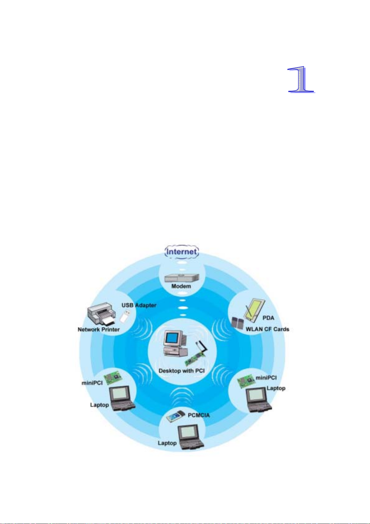
This Chapter provides an overview of the SoftGate AP/Router's features and
specifications.
Thank you for purchasing the QUETEC SoftGate wireless solution adapter. QUETEC
SoftGate is the first AP less series family product to turn the existing computers into
a wireless AP. It includes four features (4- in-1): Router, AP, Bridge, and WLAN
Client. Users can share PC resources suc h as file s, internet connection, video
streaming and multimedia title, instantly without the requirement of preinstall or
pre-configure wireless base station. SoftGate is the first technology t hat truly
removes the limitation from wireless base station.
4
Page 5

1.1 QUETEC SoftGate Features
1.1
z 4 in 1 Device— Integrates Router, AP, Bridge, and Client into your PC/Laptop.
z Easy Installation & Expansion—Simple, affordable and flexible solution break
through your wireless limitation.
z Complete Mobility—Small size, portable wireless base station.
z Security—64-bit or 128 bit encryption.
z Intelligent device— Auto-detect and configure for client or infrastructure AP.
1.2 QUETEC SoftGate Specifications
Standard
Adapter Type
Multi Mode
Modulation Technolog y
Data Encryption
Frequency Band
Channels
Date Rates & Modulation
Media Access Protocol
Supported OS
LED Indicators
Receive Sensitivity
IEEE802.11b
PCMCIA, PCI, MiniPCI, USB
Router, AP, Bridge, and Client
DSSS
64/128bit WEP encryption; TKIP (Temporal Key Integrity Protocol)
2.412 ~ 2.462 GHz (US)
2.412 ~ 2.484 GHz (Japan)
2.412 ~ 2.472 GHz (Europe)
2.457 ~ 2.462 GHz (Spain)
2.457 ~ 2.472 GHz (France)
11 (US, Canada), 13 (Europe), 14 (Japan), 2 (Spain), 4 (France)
11Mbps: CCK
5.5Mbps: CCK
2Mbps: DQPSK
1Mbps:DBSK
CSMA/CA (Carrier sense multiple access with collision avoidance)
Windows ME, 2000, XP
Power, Link, Activity
11Mbps@-84dBm
5.5Mbps@-86dBm
2Mbps@-91dBm
1Mbps@-93dBm
Transmit Output Power
Operational Voltage
Temperature
Humidity
Certifications
Warranty
Up to 17dBm
3.3/5V
Operating : -0°C to 55°C (32°F to 131°F)
Storage : -5°C to 70°C (23°F to 158°F)
Operating: 0% to 90% Non-Condensing
Storage: 0% to 90% Non-Condensing
FCC, CE, SAR
One year
5
Page 6
1.3 QUETEC SoftGate Interface description
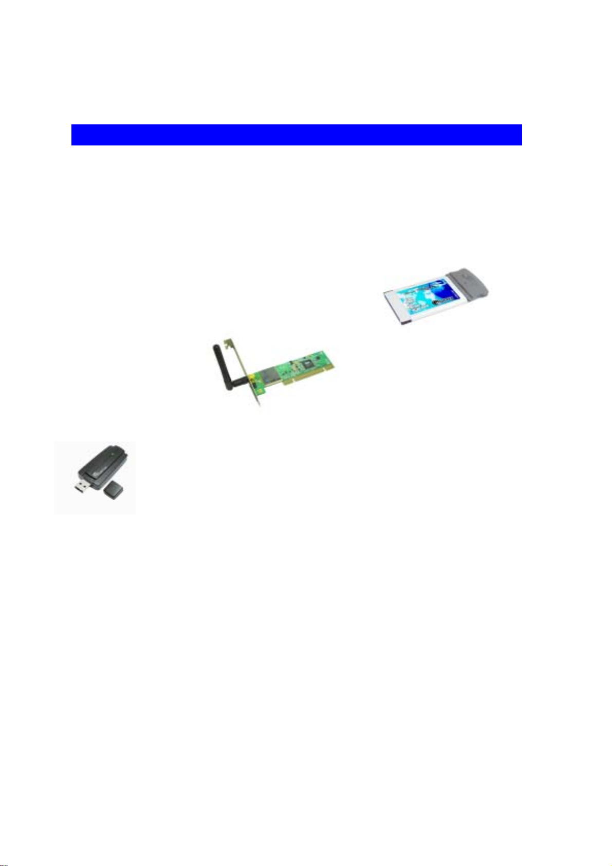
The QUETEC SoftGate AP/Router solution provides several kinds of interface:
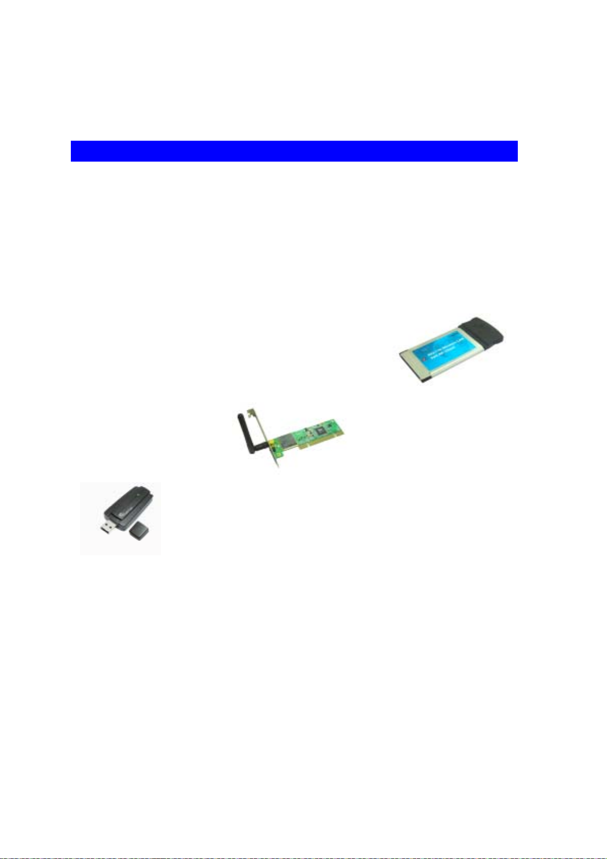
z PCMCIA: for PC card type II
z PCI: for 32 bit PCI 2.2
z USB: for USB 1.0 (2.0)
6
Page 7
Chapter 2 Installation Overview
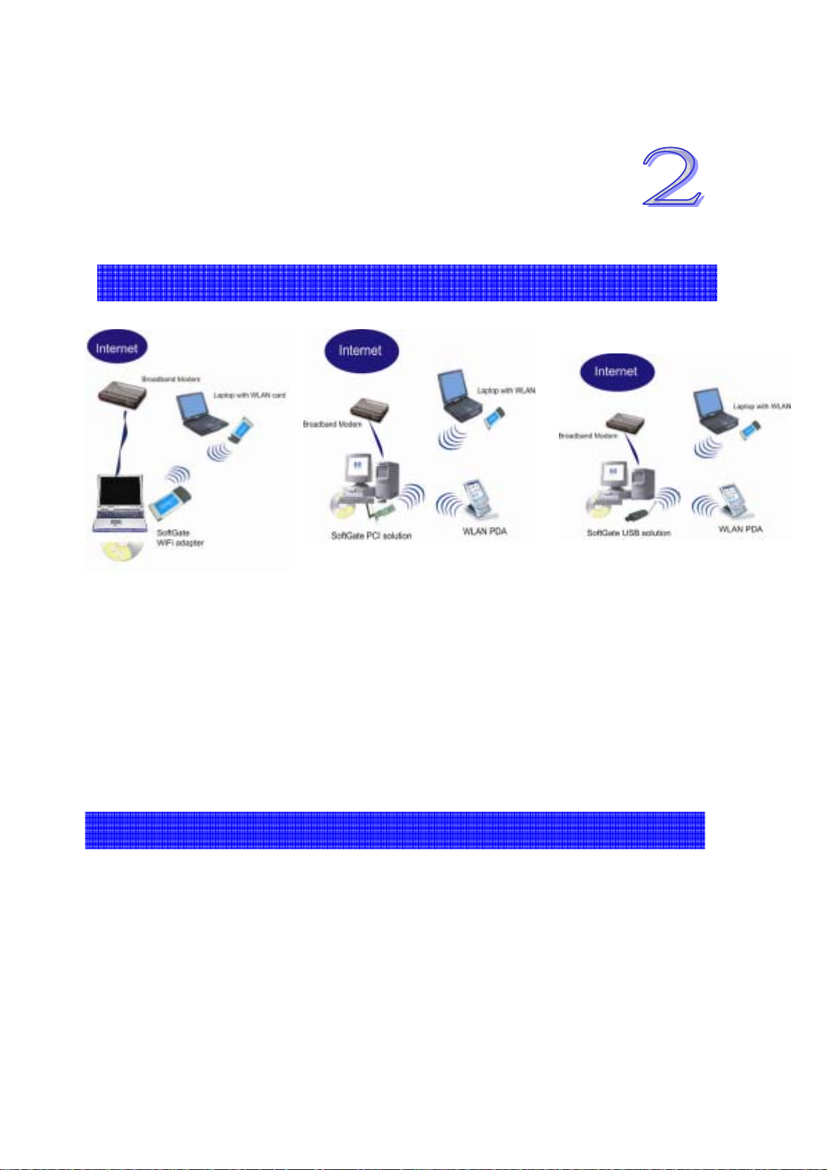
2.1 QUETEC SoftGate Setup on Laptop/Desktop PC
*
You should estimate around several minutes to complete the installation.
Before you begin the installation process, make sure you have the proper SoftGate
Wi-Fi adapter and installation CD and that the Laptop/Desktop PC which you are
installing onto has a proper ope n slot.
2.2 QUETEC SoftGate Requirements
The machine installing SoftGate needs to have supported OS running.
Make sure a proper internet connection is avail able on the installation machin e by using
the Microsoft Internet Explorer.
If you have another active Wi-Fi card, disable it before installing SoftGate by going to
Start Menu: Control Panel: System: Hardware Tab: Device Manager: Network adapters,
select Wi-Fi adapter you are running, right mouse click, disable the device.
7
Page 8
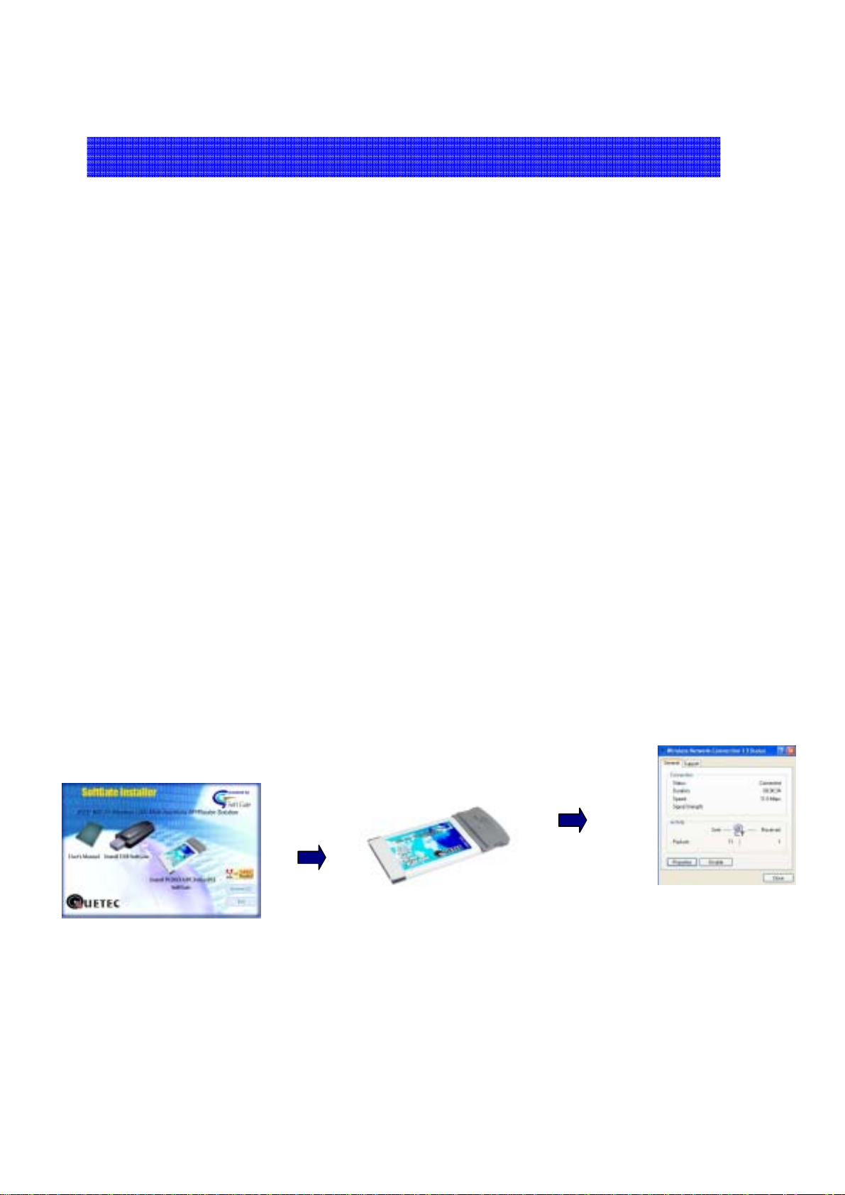
2.3 QUETEC SoftGate Quick Installation
Once you are ready to install, follow the s e steps:
STEP 1.
For PCMCIA and USB: Insert QUETEC SoftGate Soft ware CD into your computer first,
and the autorun program will launch the setup wizard, then choice the adapter icon to run the
setup program.
For PCI only: Insert the PCI adapter into your PC slot first, and then restart your PC. When
the system launch the new device wizard, please cancel it and insert SoftGate Software CD
into your computer, the autorun program will launch the setup wizard, and choice the adap ter
icon to run the setup program
STEP 2.
It will execute and configure all your need automatic. Please follow the direction of setup
wizard to insert the adapter into the suitable slot, when it told you to do so.
STEP 3.
Continue to follow the installation wizard to setup SoftGate driver and program. Then
SoftGate will turn your Laptop/Desktop PC to wireless Access Point.
8
Page 9

Chapter 3 What’s in the Box
3.1 Package content
The following items should be included
• 1 QUETEC SoftGate Wi-Fi adapter (PCMCIA/PCI/USB)
• 1 Installation Autorun CD: contents in the CD include
o SETUP.EXE: QUETEC SoftGate installer
o Userguide: User’s Guide
• 1 piece of Quick installation guide card
• 1 USB cable (for USB package only)
If any of the above items are dama ged or missing, please contact your de a l er immediately.
9
Page 10

Chapter 4 Check Your System
Please make sure again that the computer you are installing the QUETEC SoftGate
meets as followin g minimum syst em requirements:
Computer with CPU PII 366MHz or better
•
•
128MB RAM or better
• Windows ME, 2000, XP
• An open slot based on the adapter in the package
• CDROM drive
10
Page 11
Chapter 5 QUETEC SoftGate Installation Procedures
The procedures described in this section to install and configure the QUETEC SoftGate
Wireless LAN device under MS Windows 2000/XP.
Caution:
Please do not insert your PCMCIA card until the Application setup asks you to do so. The
setup procedure described below installs both the drivers and the QUET EC Sof tG a t e
Manager Utility.
If the SoftGate Manager Utility were installed before, you need uninstall the previous
version first.
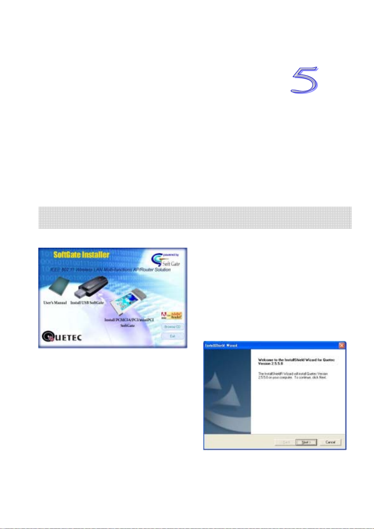
-Insert the Autorun CD to your CD-ROM and Double Click the device icon that you
want to install, and then the welcome screen is displayed.
11
Page 12
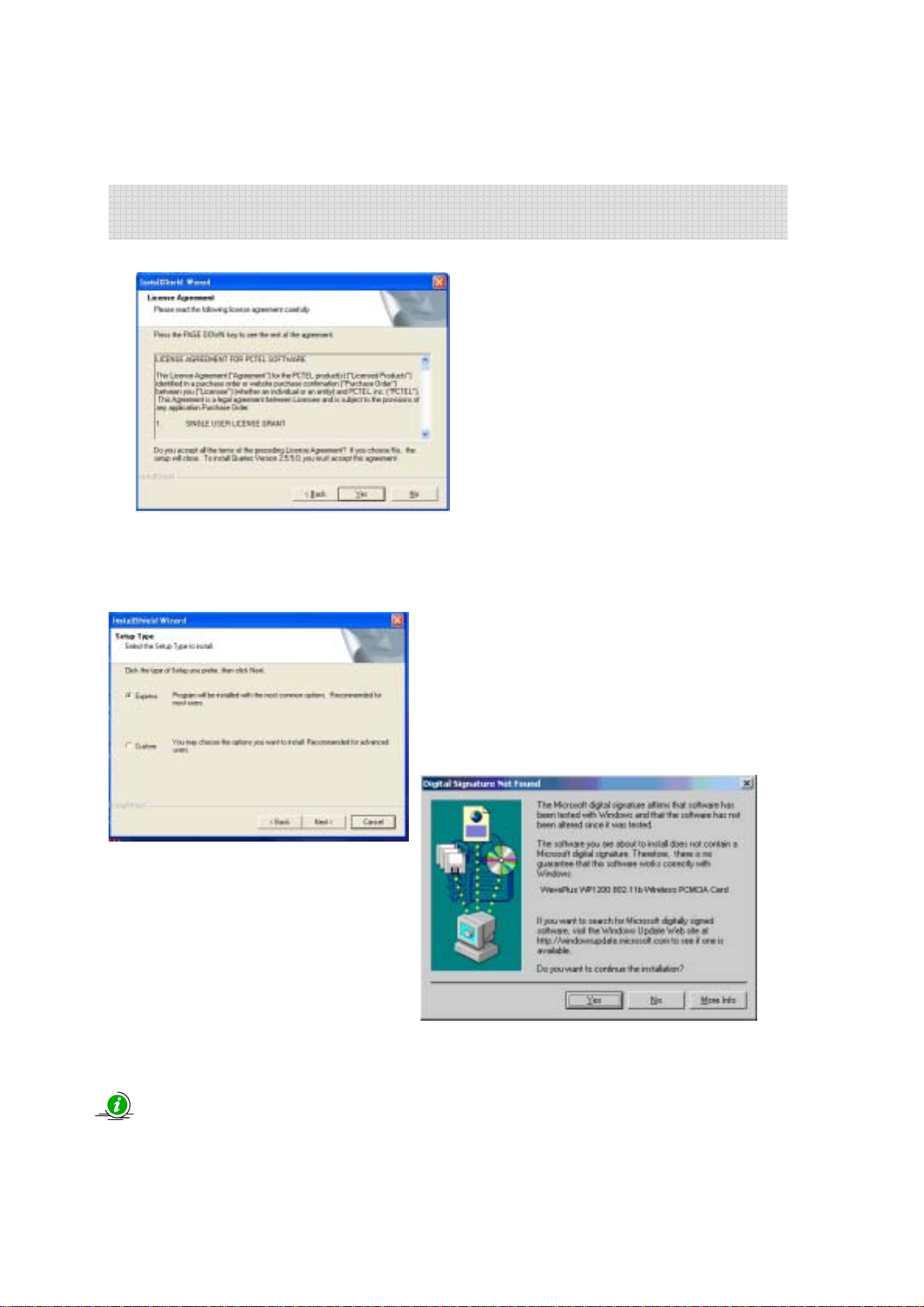
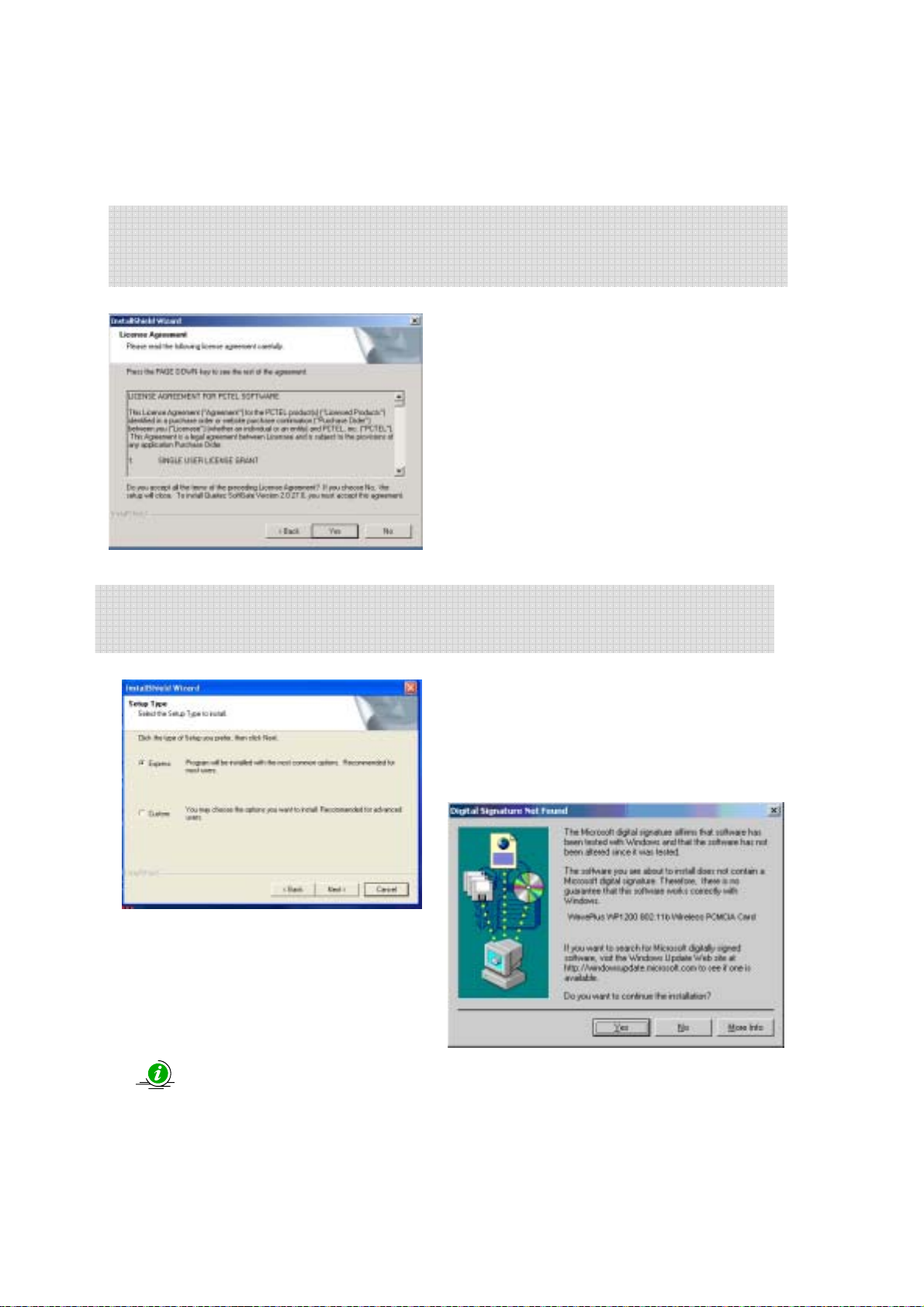
-Click on “Next”, a license agreement will be displayed,
Click on “Yes” if you agree and continue the installation.
-Click the installation type you prefer, and then click “Next” to continue.
(We recommend that you choice the “Express” at this moment)
During the set up procedure, if you see the Windows pop-up dialog shows the message about
Hardware installation warning, just click “Yes” to next step
.
12
Page 13
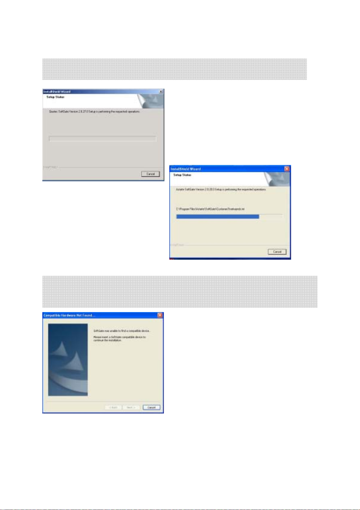
-The setup wizard will execute the installation procedure automatically,
-For the PCMCIA/USB installation, you will see a pop-up screen to ask to insert the
QUETEC SoftGate compatible device. Please insert your PCMCIA/USB into your
system, then the wizard will continue to install procedure automatically.
13
Page 14
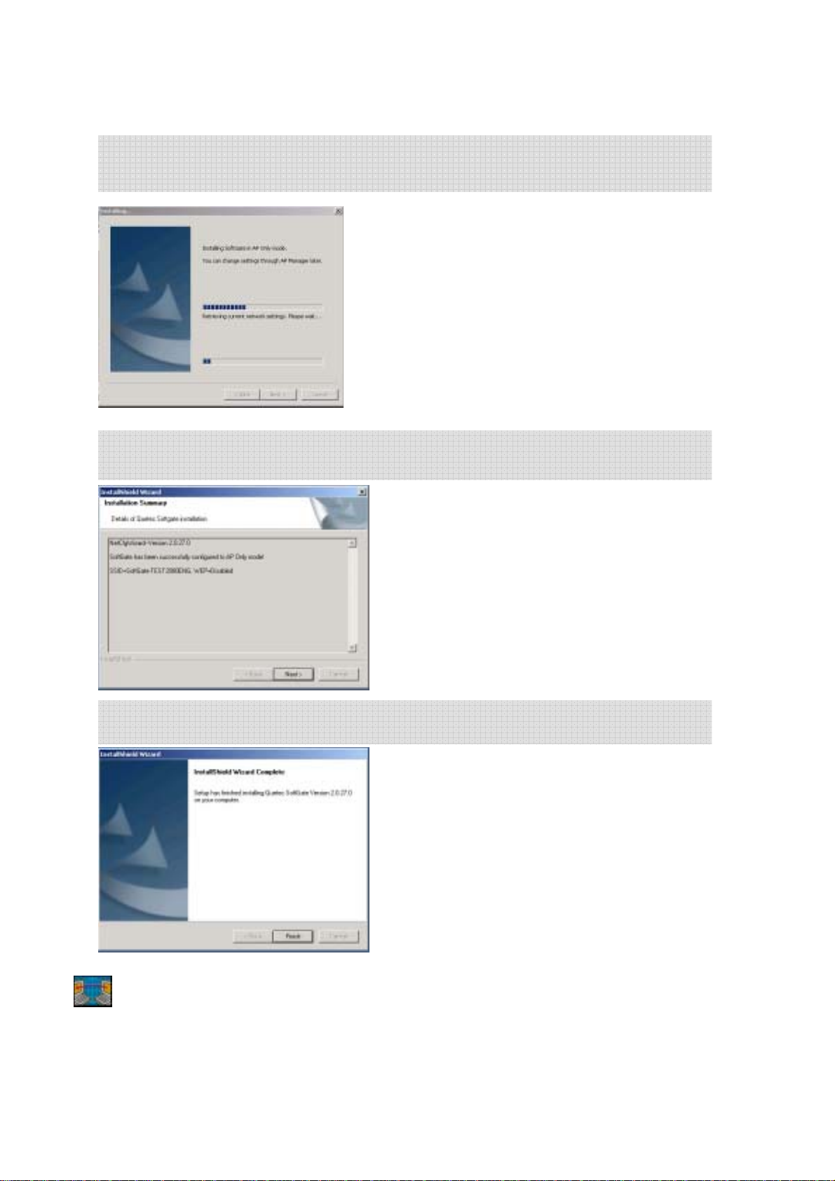
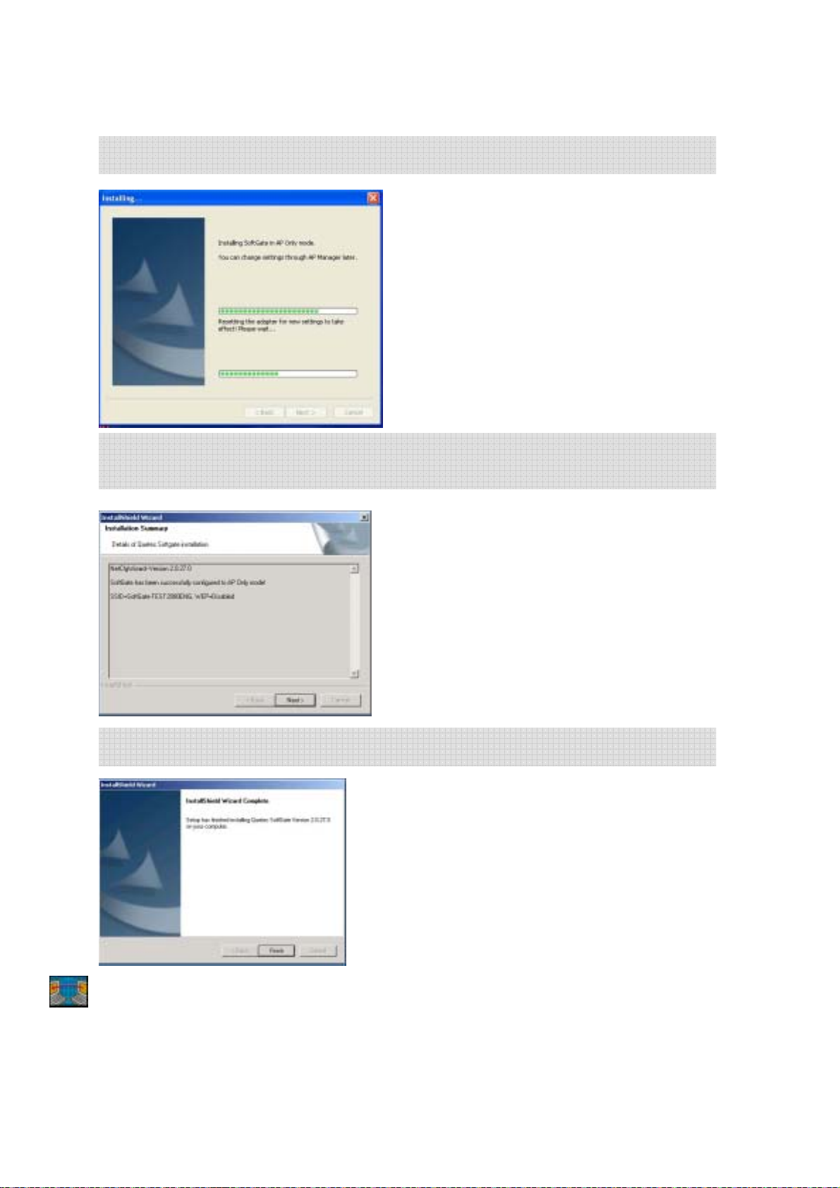
-At this moment, QUETEC SoftGate installation wizard will configure your computer
as an AP only mode.
-After the setup procedure, you will see as following message,
Click the “Next” button.
-If you see the as following message, it means the set up proced ure is completed.
You can use any other computers running Wi-Fi card to check QUETEC SoftGate
functionality. It should be listed as one of the available network.
14
Page 15

5.1 Windows ME Installation Notes
QUETEC SoftGate Installation Using a PCMCIA/USB Adapter
When installing SoftGate on a PC running Windows ME, you cannot have the
adapter inserted into the PCMCIA/USB slot during the install process.
Do not insert the PCMCIA/USB until the SoftGate installer requests you to do so.
QUETEC SoftGate Installation Using a PCI Adapter
When installing SoftGate on a PC using a PCI based wireless adapter, you must
make certain that the PCI adapter is properly installed before SoftGate
installation.
The “Add Hardware” wizard window must be closed, fully completing
the installation.
Windows Me ICS Setup
After installation SoftGate will install in client mode, you must manually configure
ICS on Windows ME to share the Internet connection. The following is the
procedure for Windows ME ICS configuration. Follow these instructions after
installing SoftGate.
1. The following steps will guide you through Windows Me ICS configuration.
• Select Start > Settings > Control Panel > Add/Remove Programs.
• Click on the Windows Setup tab, Windows will find the installed components.
• Double click on the Communications icon, check the Internet Connection Sharing box and click OK to close the
Communications window and OK to close the Add/Remove Programs window.
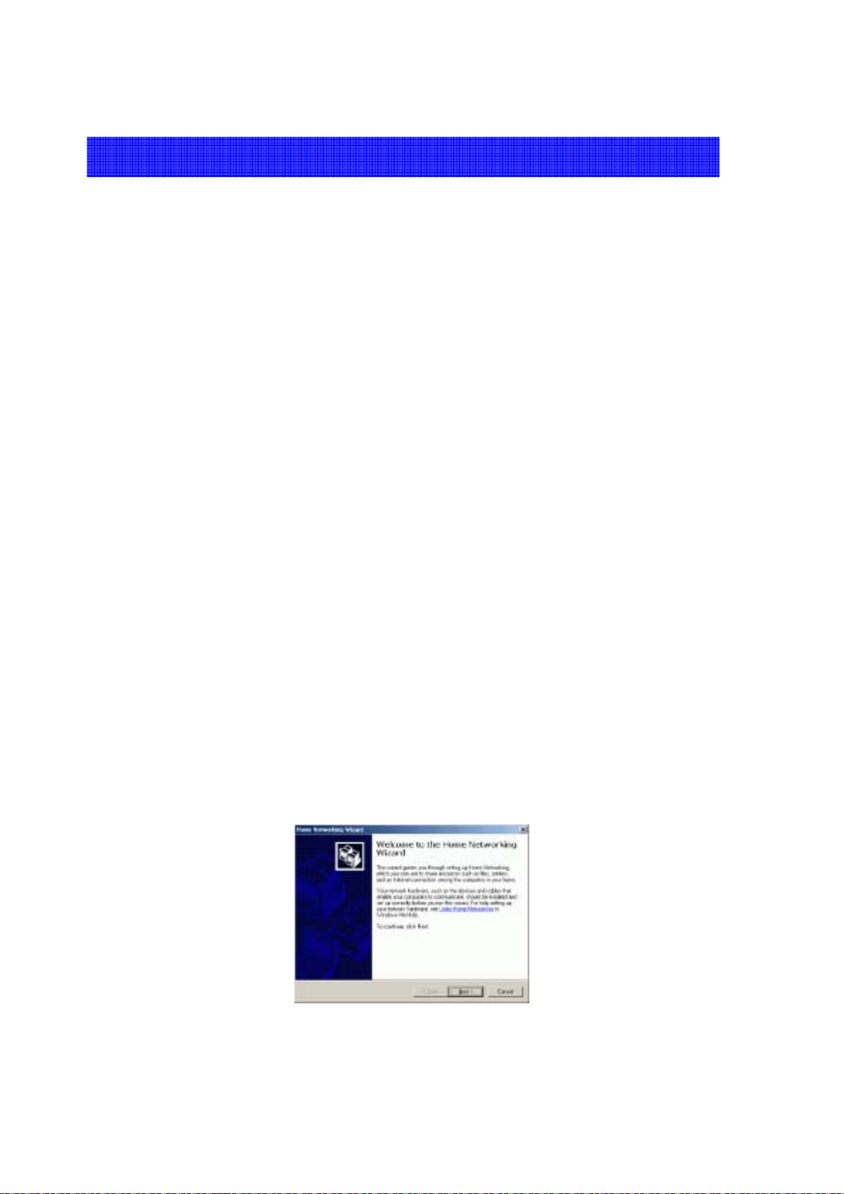
2. Microsoft ICS will install, and then launch the Home Networking Wizard.
Select next to begin.
15
Page 16
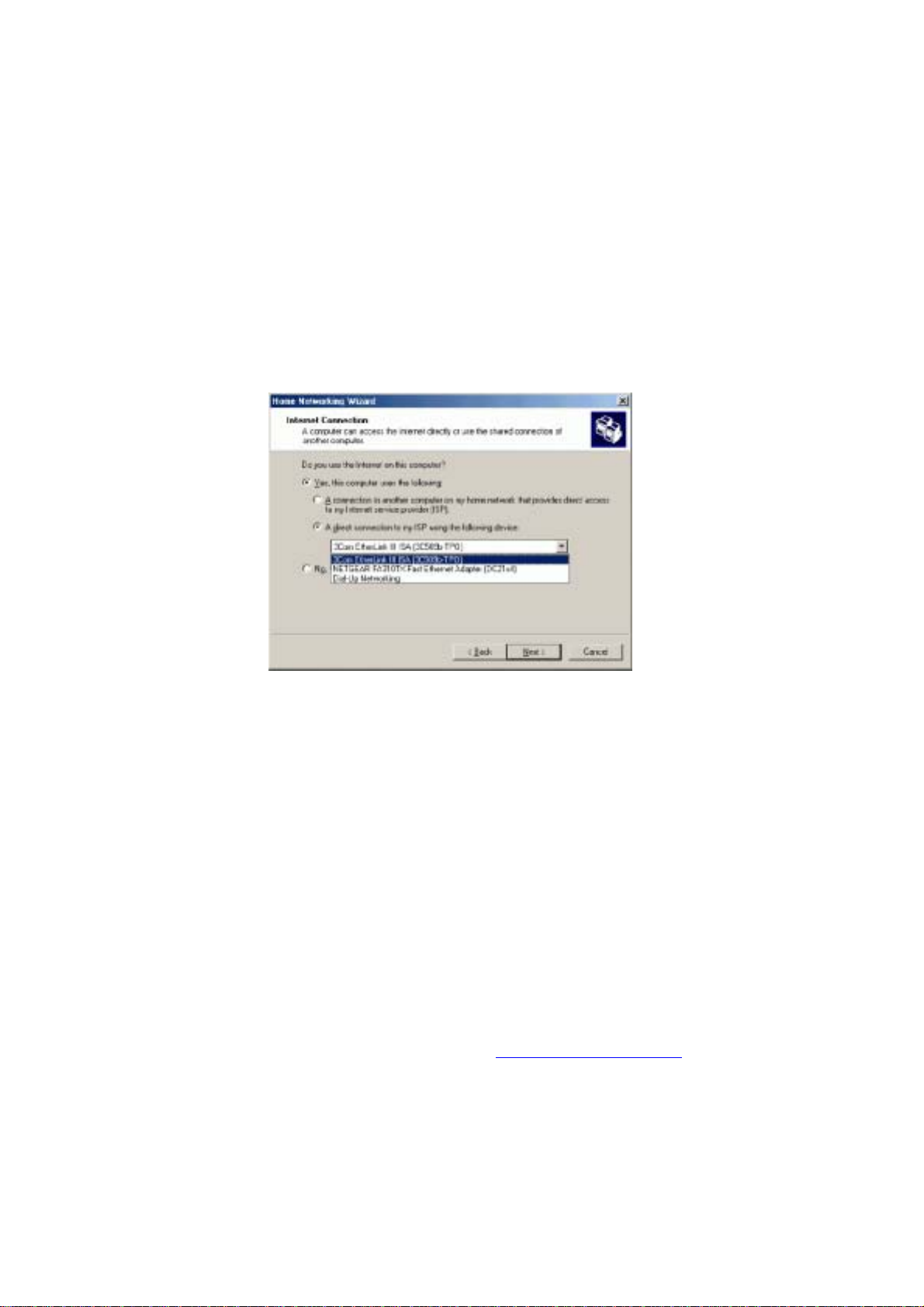
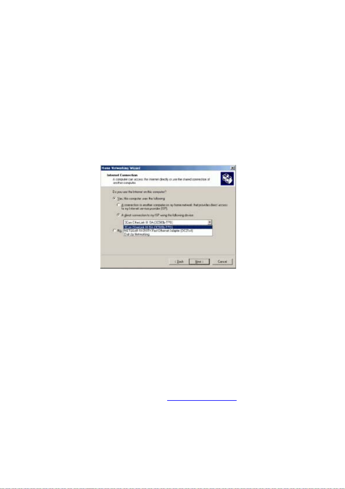
3. Because the SoftGate enabled PC will share the Internet connection select:
“Yes this computer uses the following”, and “A direct connection to
an ISP using the following device”.
4. Click the down arrow to see a list of adapters that can be shared. Select the
network adapter that is connected to your broadband modem. Press Next.
5. Select “Yes” when asked if you would like other users to be able to access
this computers Internet connection. The pull down menu gives you the choice
of adapters that other users will connect to; in this case, you must select
the SoftGate adapter from the pull down menu. Press Next.
6. The next screen will ask if you would like to create a home networking setup
disk. You can select NO, finish the installation, or you may proceed with
creating a setup disk for your other PC’s. If you choose to create a home
networking setup disk, follow the onscreen instructions.
NOTE: Please refer to your Windows Me Help guide or http://support.microsoft.com for the
Microsoft support website.
16
Page 17
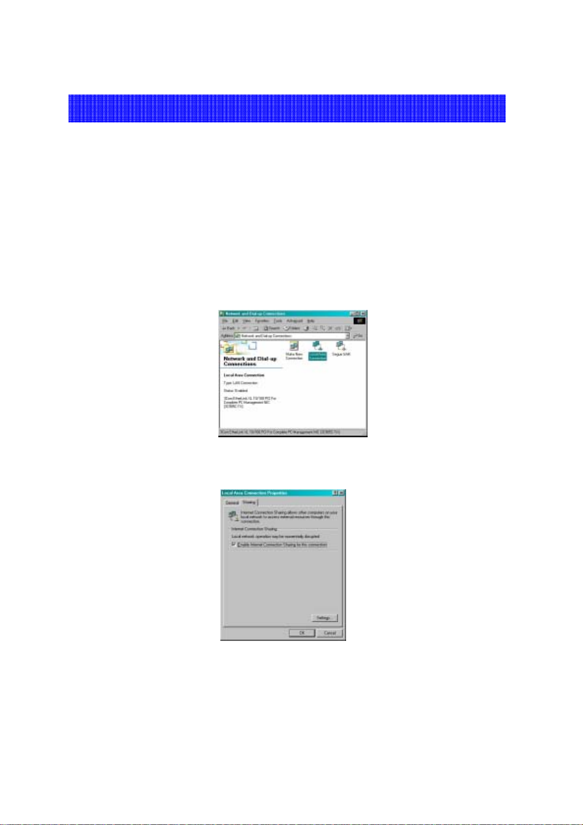
5.2 Windows 2000 ICS Setup
It is highly recommended that you upgrade Windows 2000 to Service Pack 4. If you
cannot make this upgrade, you must manually configure ICS on Windows 2000
after installing SoftGate.
1. Verify your cable modem, DSL or other broadband connection is working
properly. Verify you can connect to the Internet over your broadband co nnection.
2. Open the Properties for the network adapter that is connected to your
broadband modem and click on the "Sharing" Tab.
• To do this: Right-click on "My Network Places" on your Desktop, select "Properties", right-click on the "Local
Area Connection" icon for the network adapter that is connected to your broadband modem) select
"Properties".
3. Check the "Enable Internet Connection sharing for this connection" box to
enable ICS.
4. Clients that connect to the SoftGate enabled Access Point will now be able to share
your Internet connection using Microsoft ICS.
17
Page 18
Chapter 6 QUETEC SoftGate Manager
6.1 Overview
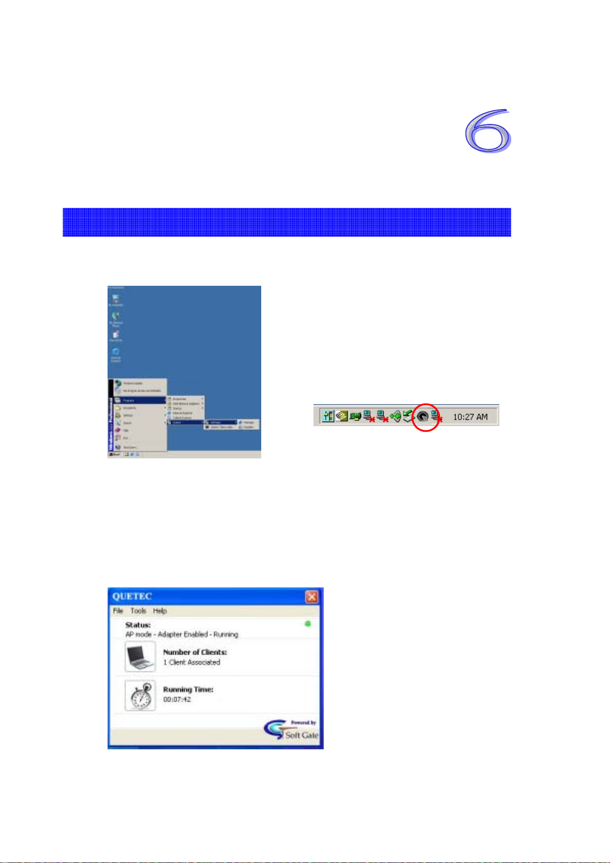
After the successful installation, you can find the following items in Start
menu: All Programs:Quetec: SoftGate. Also in your system tray.
Quetec SoftGate Manager provides detailed control of SoftGate operation.
This is the main screen of SoftGate.
• Green light blinks on the top right corner indicates proper SoftGate
operation.
• Status: Shows the SoftGate mode and adapter status.
• Number of clients: How many clients connected to SoftGate.
• Running time
18
Page 19
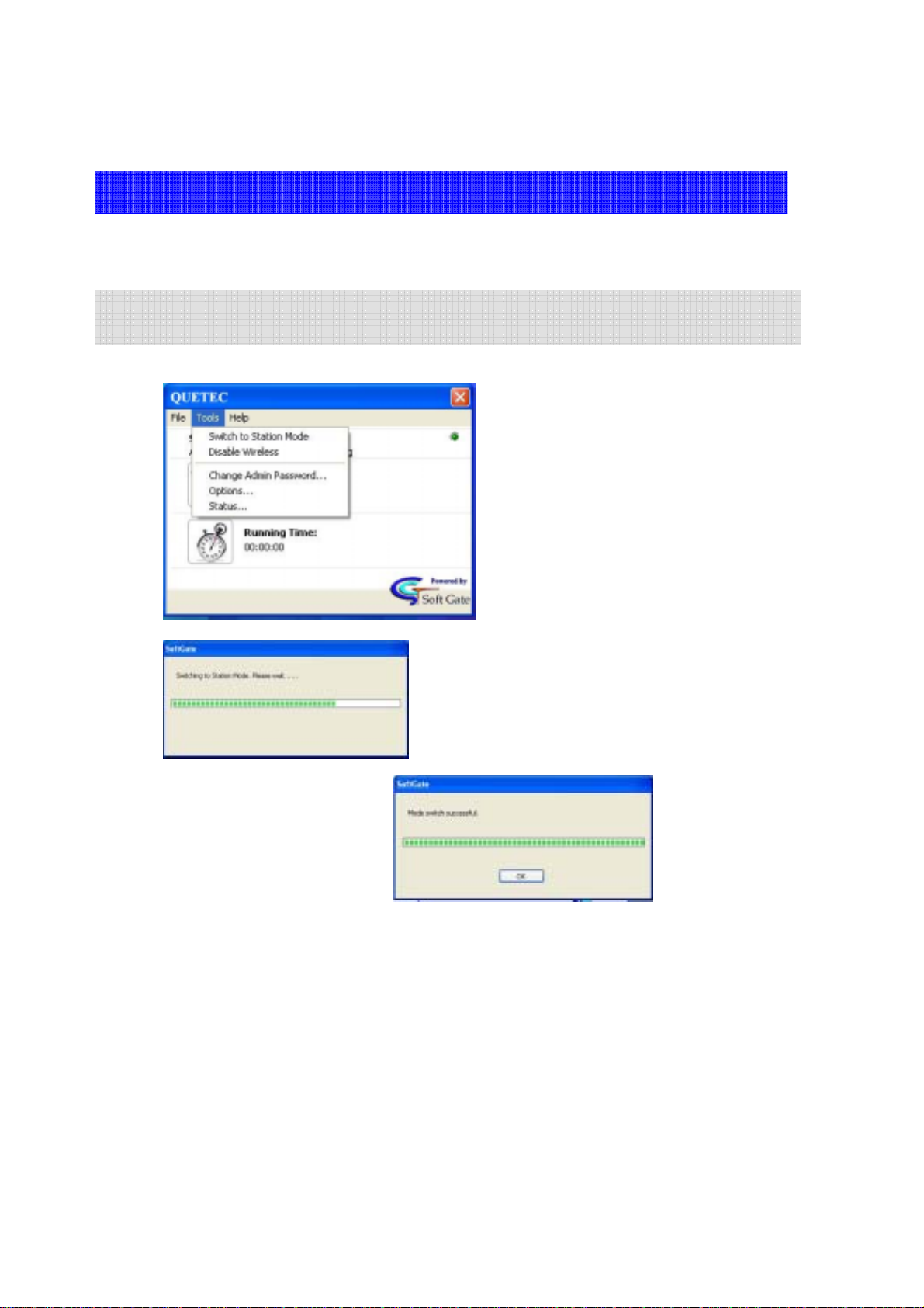
6.2 AP/Client mode setup procedures under WinXP
To access the “Options” menu select Tools>Options from the SoftGate
menu bar.
- Select “Tools”, “Switch to the Station Mode”, you can easily switch from AP to
station as you want.
19
Page 20
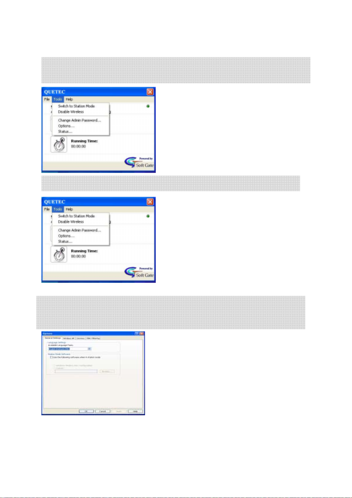
-In “Tools” section, use “Disable the wireless” to disable/enable the wireless
connection.
-Select “Tools”, “Options”, to enter the detailed setup for SoftGate Manager.
-In “Options” area, you can change wireless related settings, incl. General Setting,
Wireless AP, Devices, and MAC Filtering. To apply any changes you made, please
click on “O.K” button.
20
Page 21
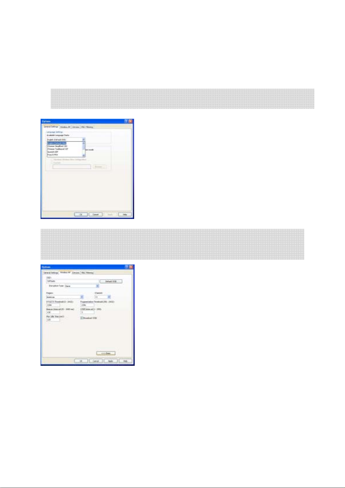
-The Wireless AP interface provides an interface for general configuration
settings for language and station mode client configuration
Language Settings: Use the pull down menu to select
the language pack for SoftGate.
Station Mode Software: SoftGate provides the
capability to operate in station mode to access wireless
access points. If a wireless access / discovery client is
installed check “Use the following software when in
station mode” and select the appropriate client software
to use when in station mode. SoftGate will automatically
launch your client utility when switched into station
mode.
-In “Wireless AP” area, you can change wireless related settings, incl. SSID, WEP,
channel and SSID broadcasting. To apply any changes you made, please click on
“O.K”. If you need to do advanced setting, click “Advanced >>>” button.
The Wireless AP interface provides configuration options
related to SoftGate’s wireless AP functionality.
SSID: Service Set Identifier (SSID) is the name that
clients will see when attempting to connect to the
SoftGate.
Encryption Type: Relates to the security features of
SoftGate. Security features are discussed in detail in
SoftGate Security.
Region: The geographic region where SoftGate is
currently being used. Region is required for SoftGate to
operate in accordance to regional regulations and specifications of use. You must select the
region you are currently using SoftGate in.
• Americas
• Singapore
• Taiwan
• Japan
• Europe
21
Page 22
• Israel
• China
• France
• Spain
Channel: The 802.11 wireless channel that SoftGate will use to broadcast traffic.
Advanced Settings (Button): Fine tuning of SoftGate network settings - primarily for
network troubleshooting or expert users.
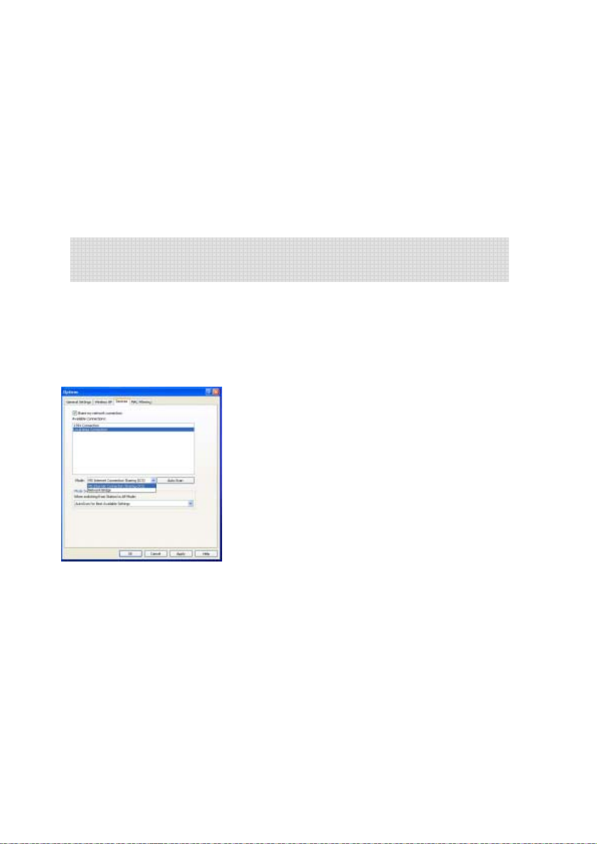
-In “Devices” setting area, you can change the network connection mode. e.g.
move from office to home, you can use “ICS/Bridge Settings” to redirect the
network settings, and also to share the network conne ction.
Although the installation process will automatically configure SoftGate correctly based on
the current network conditions, there will be times when the configuration will require
modification.
Note: You will need to manually configure ICS on Windows ME and Pre Service
Pack 4 on Windows 2000.
Share My Network Connection (Check Box): To
enable Internet Connection Sharing (ICS). Typically, you
will use this setting when the network does not support
DHCP services, i.e. on your network at home.
Available Connections: The window displays available
network connections that can be configured through
SoftGate.
Mode: The current network mode that SoftGate is
currently set to when sharing an Internet Connection:
MS Internet Connection Sharing: This mode provides
Internet Connection Sharing to client connected to
SoftGate through Microsoft ICS services. Clients connecting to SoftGate mu st be
configured to obtain IP addresses automatically. This option is set in the TCP/IP
interface on the client computer’s network configuration for their wireless
adapter.
Bridge Mode: This setting will be used to share Internet connectivity by
bridging the current LAN adapter connected to the wired network and the
wireless adapter SoftGate utilizes to provide wireless Access Point services.
Typically, this mode is used on networks that provide DHCP services i.e. your
office network.
Auto Scan: SoftGate will configure settings based on a scan of your current network
conditions. In most cases, you will choose this option for best results.
22
Page 23
Mode Switch Options: This setting allows you to configure SoftGate to automatically scan
for the best available settings when you switch from station to Access Poin t mode . Use th e
pull down menu to choose the mode switch
• Auto Scan for Best Available Settings
• Prompt for Connection Settings
• Use Previous Settings
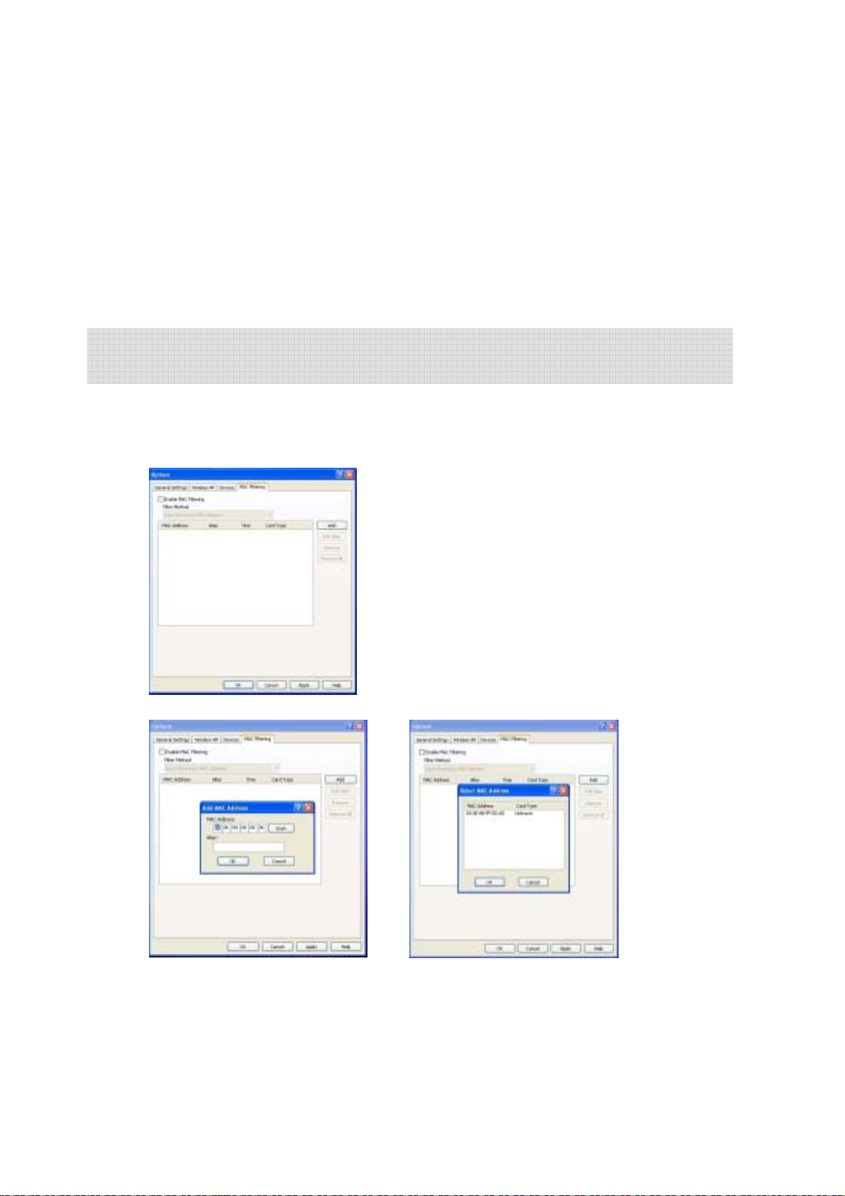
-Enter the “MAC Filtering setting” area to enable the MAC filtering function,
choice the filter method that you want to use.
The MAC filtering interface provides the capability to explicitly allow or deny a client device
access to the SoftGate enabled network. MAC filtering is a security feature of SoftGate that
is discussed in detail in SoftGate Security.
23
Page 24
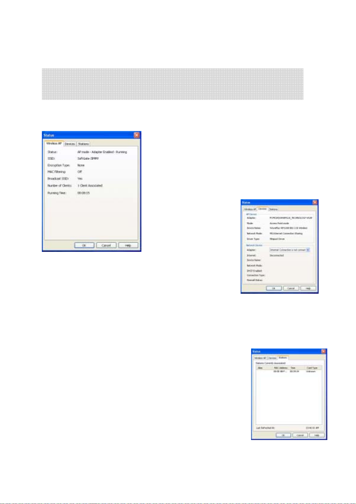
-Choice the “Status…”menu to monitor the wireless AP, Devices and Stations
(Status of connected clients) status. To access the “Status” menu select Tools>Status
from the SoftGate menu bar
The SoftGate status menu provides various in terfaces that allow the SoftGate administrator
quick and easy access to the overall configuration details of SoftGate. The Status menu
provides three interfaces:
SoftGate Wireless AP Status
The current configuration of the SoftGate can be
viewed in the “Wireless AP” interface. This interface
provides a single view of the network status, security
settings, number of clients currently associated, and
how long SoftGate has been running.
SoftGate Stations Interface
The SoftGate “Stations” interface provides details on each client that
is currently associated with the SoftGate AP. The interface provides
the following information about connected clients:
• Alias – A user-friendly name that is associated with the device. The Alias must be
configured using the MAC filtering interface
• MAC Address – The MAC (Media Access Control) address of the client device.
• Idle Time – The elapsed time since SoftGate has received any
active traffic from the client.
• Card Type – The manufacturer or vendor name of the clients
wireless network adapter.
24
Page 25
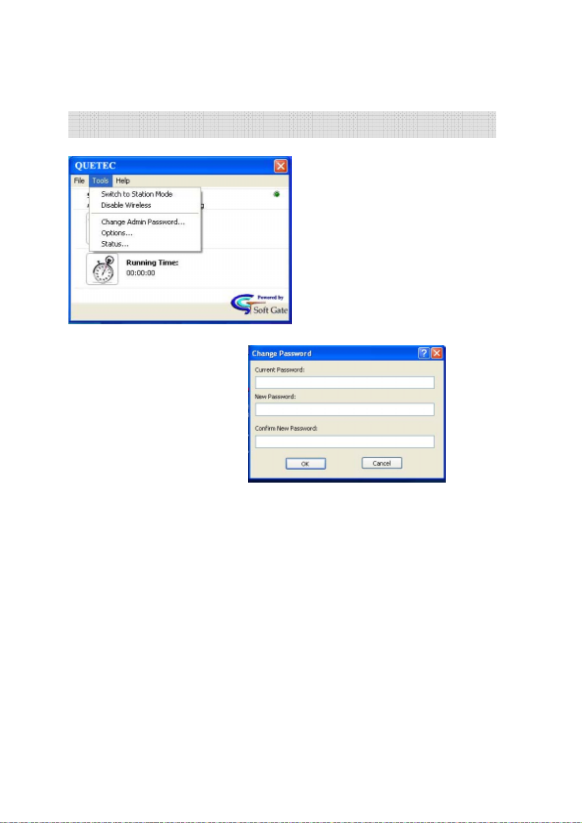
-Choice the “Change Admin Password…” to change your SoftGate password.
25
Page 26
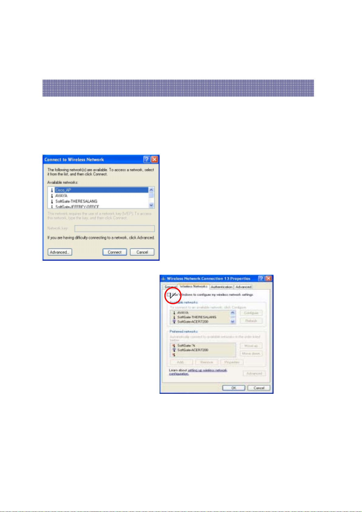
* Client mode function under WinXP
Under WinXP system, please using default wireless network utility when switching to
station mode. You can find it on “Control panel”: “Networking”.
Make sure to choice “Use Windows to configure my wireless network
settings” to enable wireless client function.
26
Page 27
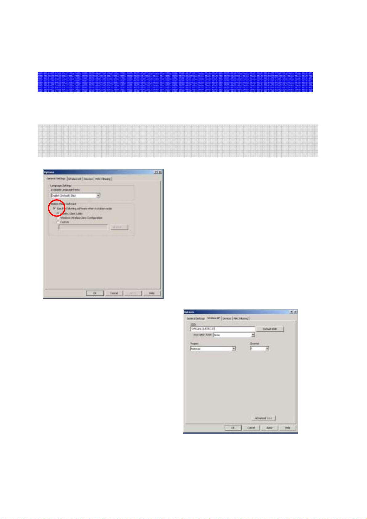
6.3 AP/Client mode setup procedures under Windows 2000-
The Windows 2000 AP set up procedures is almost the same as WinXP,
only for the client function choice must do some changes as following:
- In “General Settings” at “Station Mode Software”, mark the “Use the following
software when in station mode”, and make your selection. (We strongly recommend
you to use the QUETEC client utility as your station mode software)
27
Page 28
z
Client mode function under Windows 2000-
for PCMCIA and PCI Interface
z
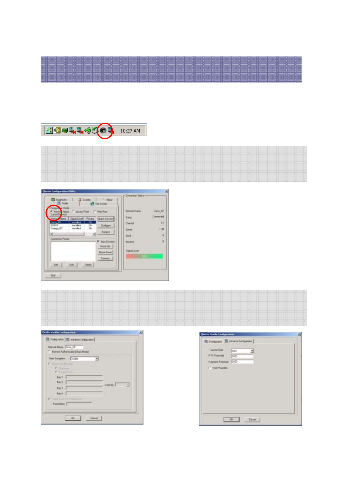
You can find the QUETEC client utility icon in the system tray when you are in
Station mode. Double click utility icon start using the program.
- In “Profile” section, can select different configuration modes.
- Push the “Refresh” button, it can show all available wireless network/APs.
- Select one network name and push the “Quick Connect” button, you can easily
connect to the wireless network.
- In “Profile” section, you can do configuration by pushing “Configure” button.
- Enter “Configuration” area to change Network Name, enable Data Encryption.
- Enter “Advance Configuration” area to change Transmit Rate, RTS Threshold,
Fragment Threshold.
28
Page 29
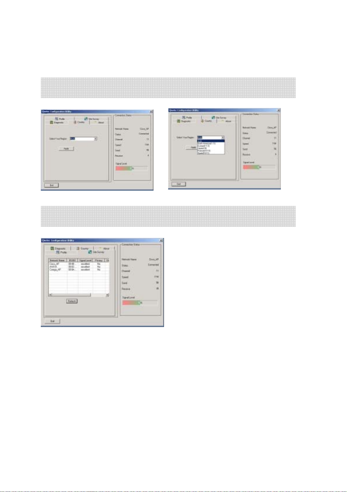
- From “Country” section, you can do select your region and push “Apply” button
to enable the change.
- In “Site Survey” section, you can get the updated network information via
pushing “Refresh” button.
29
Page 30

z
Client mode function under Windows 2000-
for USB Interface only
~ This section is only for SoftGate USB solution under station mode. For the PCMCIA
and PCI solution, please refer to PCMCIA and PCI section. ~
You can find the wireless client utility icon in the system tray when you are in
Station mode. Double-click the crab icon, following dialog box will appear.
The “NetStatus” tab shows the Link Status, Network mode, SSID, Channel, Tx.
Rate. You also can change your Ad hoc/Infrastructure network, Data Encryption,
SSID, Channel, Tx Rate in this tab. Push “change” button to choose the items.
*Network Mode:
Two types for wireless network
-Peer-to-peer (Ad hoc) network
-Access point (infrastructure)
* Network Security:
-Support Network Authentication
-Support Data Encryption.
* SSID:
-Show the connected AP’s SSID.
* Default set Channel:
-Show currently channel and provide the
channel selection function.
* TX Rate:
-Show currently data transferring rate and
provide the rate selection function.
30
Page 31
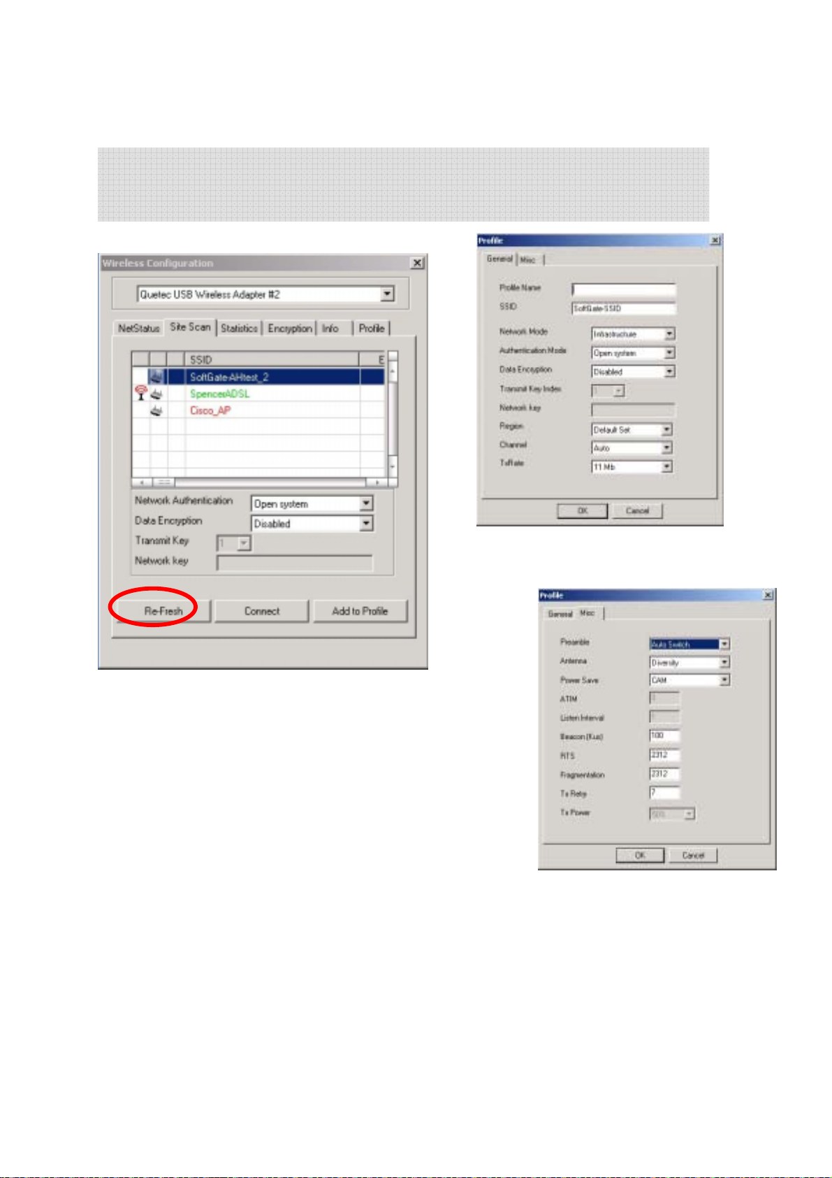
In “Site Scan”, Push “Re-Fresh” button to survey all available AP sites, You can
assign Access Point or Ad-hoc devices which you want to connect. Push the
“Connect” button to link the AP. It also provides the “Add to Profile” function.
*The “Add to Profile” function provide user to save its wireless
connection data into Profile database. Just push the“Add to
Profile” button, and it will pop-up as following dialog windows
that showing the detailed data.
31
Page 32
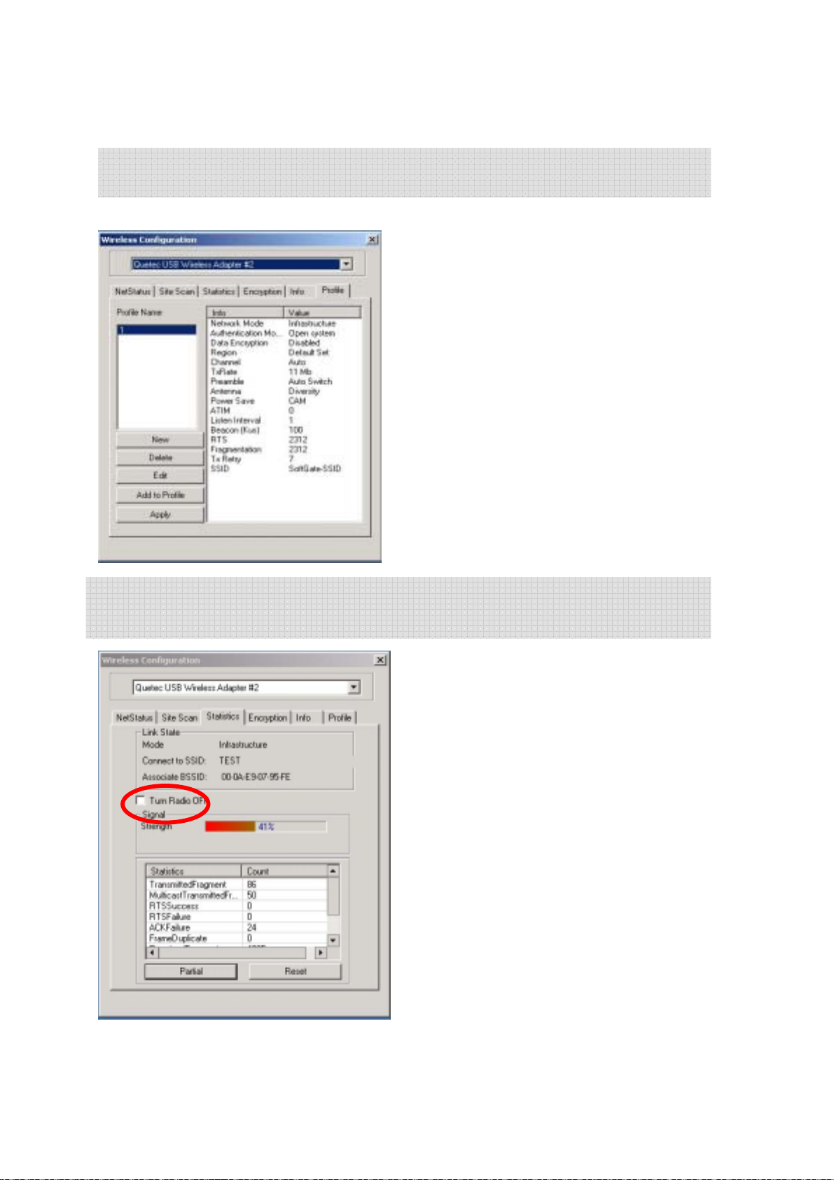
Find the “profile” data in this tab. You can add new profile or edit pervious one in
this session.
Select the “Statistics” tab, you will see the Link Status, Signal strength, and
transmit/receive statistics. If check the Turn Radio OFF, the radio interface will be
turn off.
32
Page 33
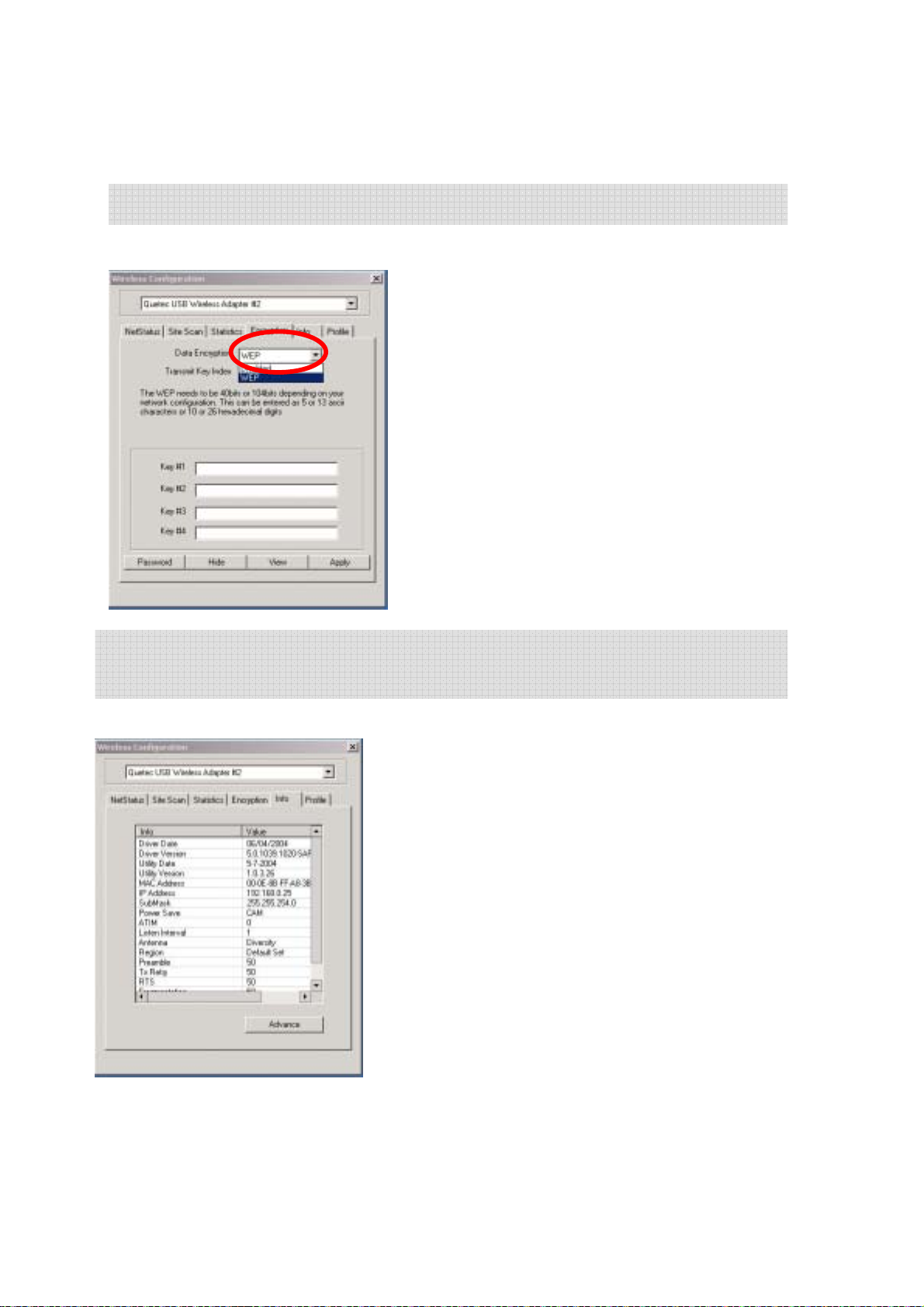
Select the “Encryption” tab. If you want to enable the function, please set the Data
Encryption to WEP.
The “Info” tab shows the detail including Driver version, Configuration Utility, and
NIC firmware version. Users must use this version number when reporting their
problems for technical support.
WEP encrypts each frame transmitted from the
radio using one of the Keys entered from this panel.
To be written to the driver and registry, each key
must consist of hex digits, which means that only
digit 0-9 and letters A -F are valid entries. If entered
incorrectly program will not write keys to a driver.
* For more detailed setting, please refer to QUETEC
SoftGate Security section.
33
Page 34
6.4 QUETEC SoftGate Security
As mentioned in the SoftGate introduction, securing your SoftGate enabled network is essential in a
wireless network environment.
Security for the SoftGate enabled wireless network is maintained through three primary
features:
• Support for the Wired Equivalency Protocol (WEP)
• Support for MAC address filtering
• Automatically enables MS ICF on Windows XP (MS Internet Connection Fire wall)
WEP Key Configuration
The wired equivalency protocol or
moderate level of security for wireless LAN’s. Using WEP will provide enhanced security to
your SoftGate powered network, providing network authentication and data encryption.
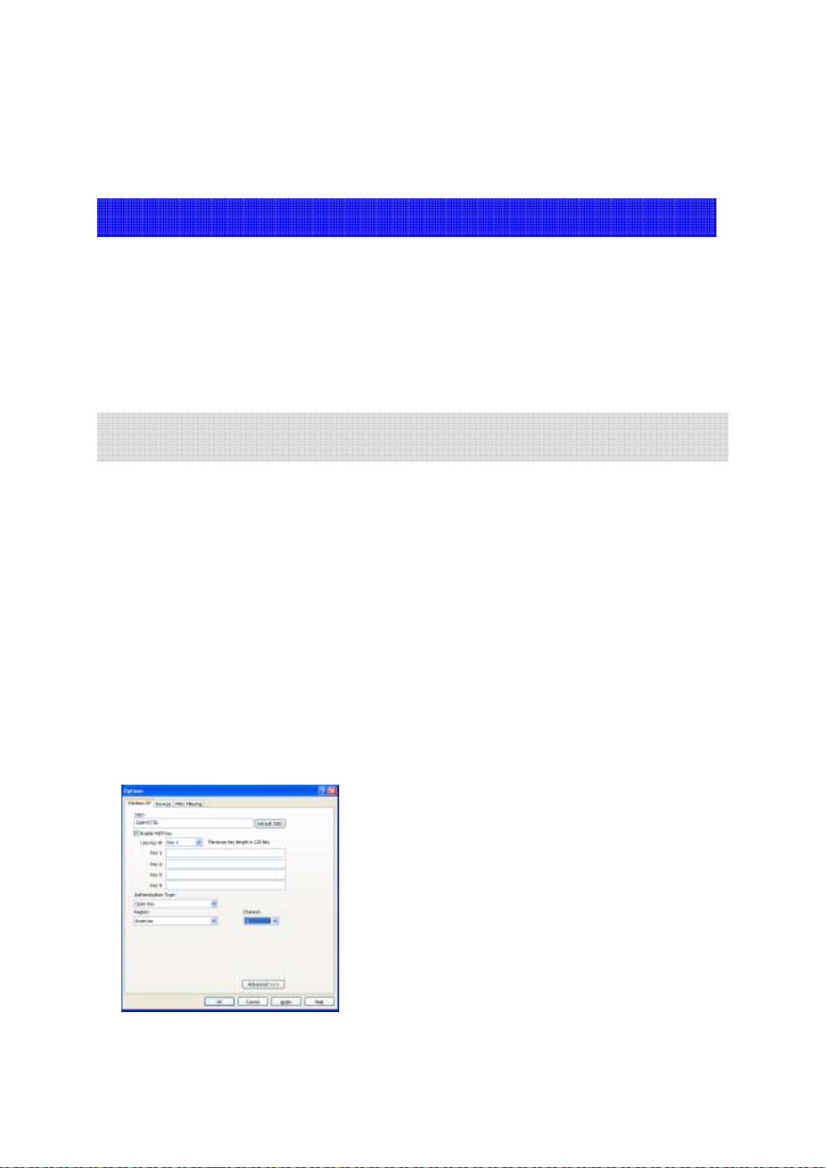
SoftGate allows the user to enter a 40 or 128 bit WEP key when installing SoftGate. The
user simply enters the WEP key in either ASCII or Hex format and SoftGate automatically
configures the SoftGate host to use WEP with the provided key. Clients that attempt to
associate with the SoftGate host will be required to supply the WEP key.
SoftGate allows you to enter and store up to 4 keys, although you may only use one key at
any given time. The interface provides the capability to quickly switch keys using the pull
down dialog box “Use Key #”.
Clients that connect to SoftGate must be configured to use WEP, and they must be
configured with the correct WEP key before attempting to connect to SoftGate.
Figure shows details the “Wireless AP” interface where WEP security is configured.
WEP
is an 802.11 encryption standard that provides a
Note: Use the following guidelines for entering WEP keys in
ASCII or Hex format:
HEX: 10 characters in HEX notation for 40 bit, or 26 characters for 128
bit
ASCII: 5 characters for 40 bit, 13 characters for 128 bit.
34
Page 35
MAC Address Filtering
SoftGate supports MAC address filtering for either allowing or denying access to individual
clients. A MAC address (Media Access Control) is a unique hardware address for networking
equipment. The MAC address is used by the network for associating an IP addresses to a
users networking hardware, in this case their wireless LAN adapter. Because each MAC
address is unique, it is suitable to use a MAC address for filtering purposes.
MAC Filtering User Interface
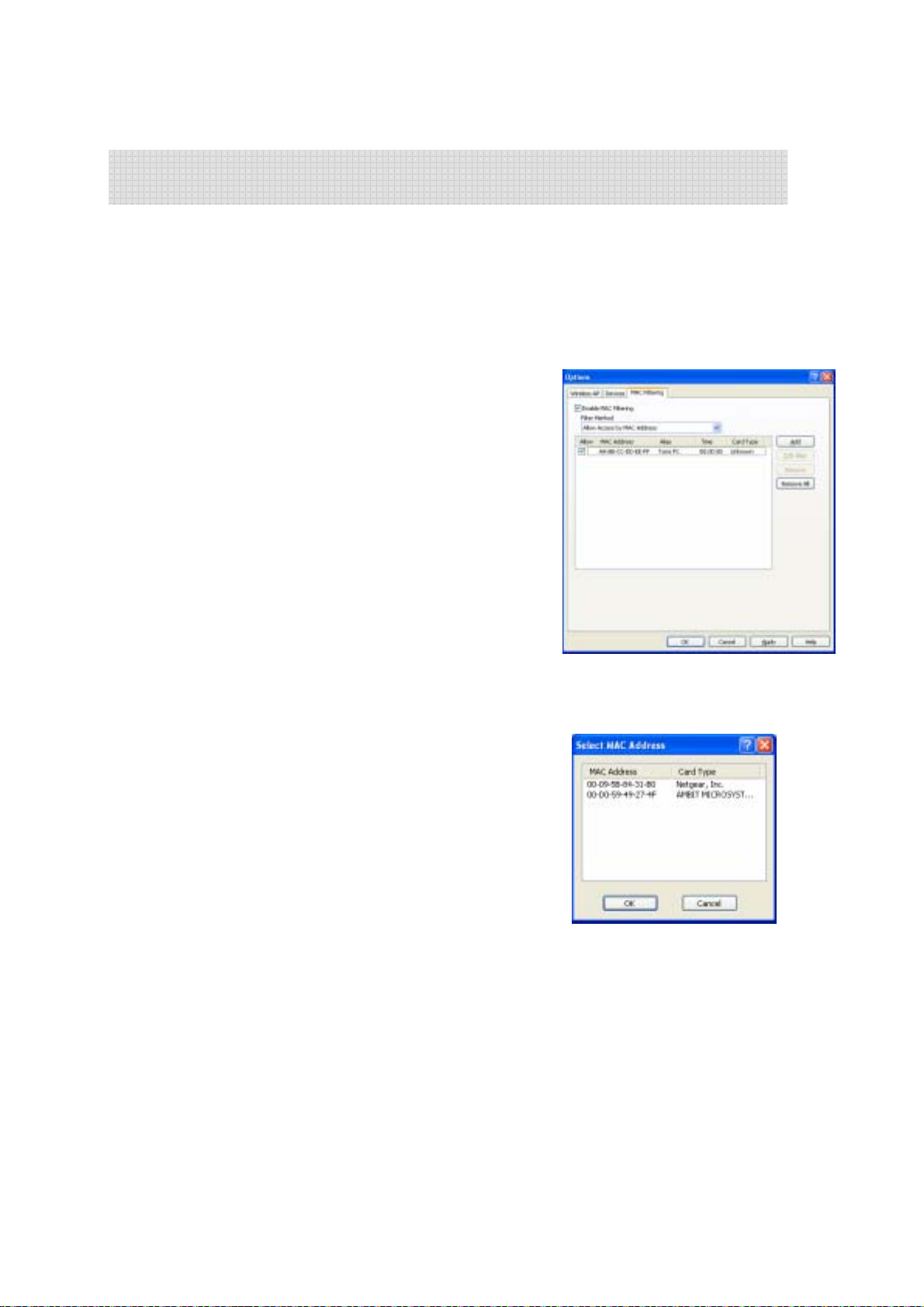
The MAC Filter configuration interface that allows the
SoftGate host user the ability to configure SoftGate to
explicitly “Deny” or “Allow” access to the SoftGate
network based on MAC address of the client adapter.
When “Allow Access” method is chosen, only the listed
MAC addresses that are checked will be granted access to
the SoftGate enabled network (This is also true even if WEP
is enabled and the user enters the correct key).
When “Deny Access” is the method chosen, listed MAC
addresses that are checked will be denied access to the
SoftGate enabled network.
Adding MAC Addresses
Simply press “Add” from the main MAC filtering
interface. A dialog will appear that allows the user to
add an explicit MAC address to filter, or the user can
“Scan” currently connected users MAC addresses.
Using a MAC Alias
The “Add MAC Address” interface provides the ability to add a user-friendly id to the MAC
address, making it easier to identify a user when vi ew ing the connected station list
35
Page 36
Chapter 7 QUETEC SoftGate Appendix
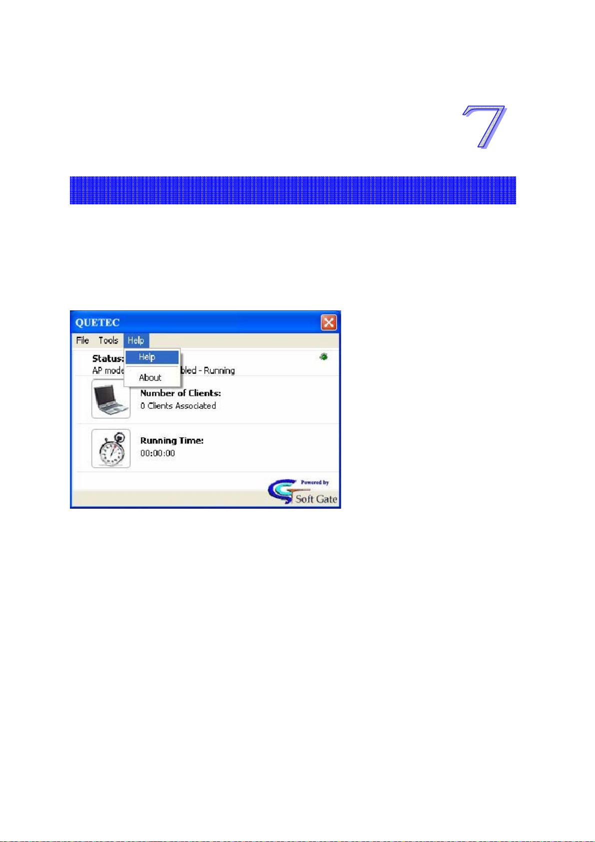
7.1 Appendix A: Quetec SoftGate Help Interface
Quetec SoftGate Help Interface
SoftGate features a comprehensive “Help” interface that provides quick answers to common
questions concerning SoftGate network modes and configuration. To access the SoftGate
“Help” interface, simply select Help from the main toolbar menu.
36
Page 37

Chapter 8 Troubleshooting
The following are known issues with the SoftGate:
8.1 Standby/Resume Cycle
During a standby and resume cycle, SoftGate may stop functioning. If this happens,
please restart the comp ute r .
8.2 Connect to SoftGate but can’t access internet
If a client machine connects to the SoftGate, but cannot access the internet, check that
the SoftGate machine has internet access. Run “ipconfig” and make sure that the
SoftGate has two connections, one for the internet and one for the SoftGate.
8.3 Quetec SoftGate Three network modes overview
During installation of the SoftGate, the installation process initiates a network configuration
and discovery routine and sets SoftGate into a mode that is appropriate for your current
network environment. It is important to understand the modes av ailable, and why SoftGate
has defaulted to the particular mode during setup. It is also important to understand these
modes from the perspective that the SoftGate host can be portable AP device that will be
run under varying network conditions.
The following sections describe the basic functionality of SoftGate network modes and
provide an essential foundation for ongoing configuration of SoftGate in a “real-world”
environment.
The three network modes available are:
¾ Access Point Only Mode
¾ Network Bridge Mode
¾ MS ICS Mode (Microsoft Internet Connection Sharing Mode)
37
Page 38
Access Point Only Mode - Overview
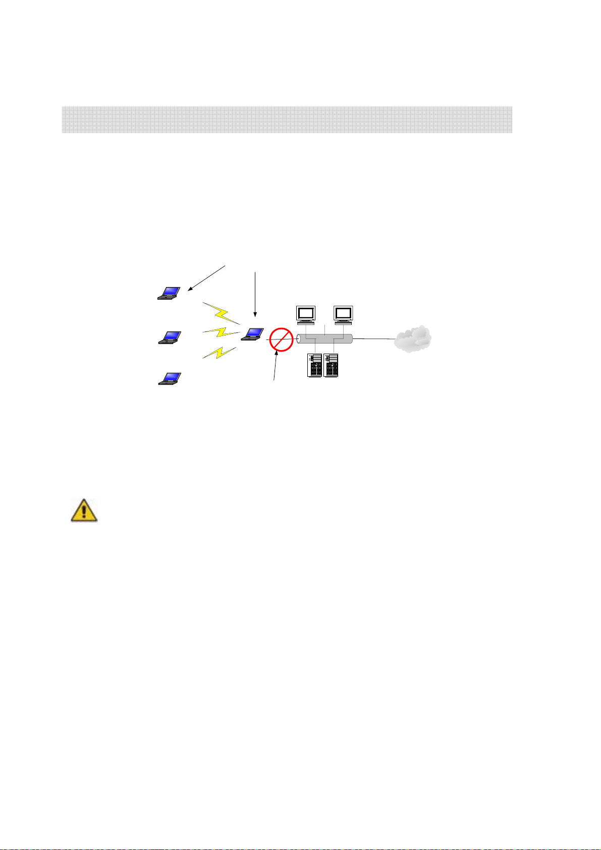
Access Point only mode provides basic access point functionality in a closed network
environment. Typically, this mode is configured when an external LAN is not available. This
mode is the default mode that is configured if the SoftGate host PC is not connected to an
external network through a wired LAN adapter.
From a network topology, AP only mode appears as:
SoftGate in AP Only Mode
Static or Auto Assign IP
Address for Host and
Client Machines
SoftGate Client
SoftGate Client
SoftGate Host
Workstation Workstation
Ethernet
Internet
SoftGate Client
No LAN Connectivity
Available
Server Server
Figure 1: SoftGate in AP Only Mode
NOTE: In AP only mode there i s no connectivity to an external LAN; therefore, there are no DHCP services available to
clients that are configured to obtain IP addresses from the network. Both clients and SoftGate host must have a valid IP
address or communication between clients or clients to host will not occur. An IP address must be assigned to the host and
client either by automatic IP address assigning (XP only) or by assigning a static private IP address to each client.
38
Page 39
Microsoft ICS Mode Overview
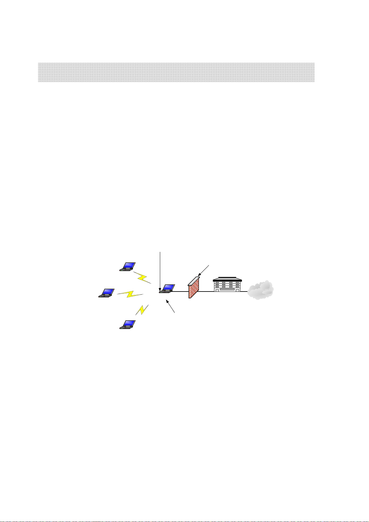
MS ICS (Microsoft Internet Connection Sharing) mode provides wireless AP connectivity to
SoftGate clients and Internet Connection Sharing to an existing LAN through the SoftGate
hosts LAN adapter. When SoftGate is configured in MS ICS mode, SoftGate clients are
leased IP addresses using DHCP services from the Soft Gate host. The range of IP addresses
assigned to clients in this mode are 192.168.0.0-255.
A typical scenario for configuring SoftGate in ICS mode is when the SoftGate host computer
is leased a single IP address from an ISP and multiple computers need to share a single
network connection through the ISP. The SoftGate host will provide wireless AP functionality,
DHCP service, and NAT services to SoftGate clients in such an environment.
SoftGate in Microsoft ICS Mode
SoftGate Host serving as DHCP server to SoftAP Clients
SoftGate Client
SoftGate Client
SoftGate Client
via Wireless LAN Adapter
Quetec? SoftGate
Configured Laptop
Wired LAN Adapter to Network
Assigned IP Address from ISP
MS ICF Firewall
SoftGate Automatically
Configures MS ICF in
Windows XP
Figure 2: SoftGate in Microsoft ICS Mode
Internet Service
Provider
Internet
39
Page 40
Bridge Mode Overview
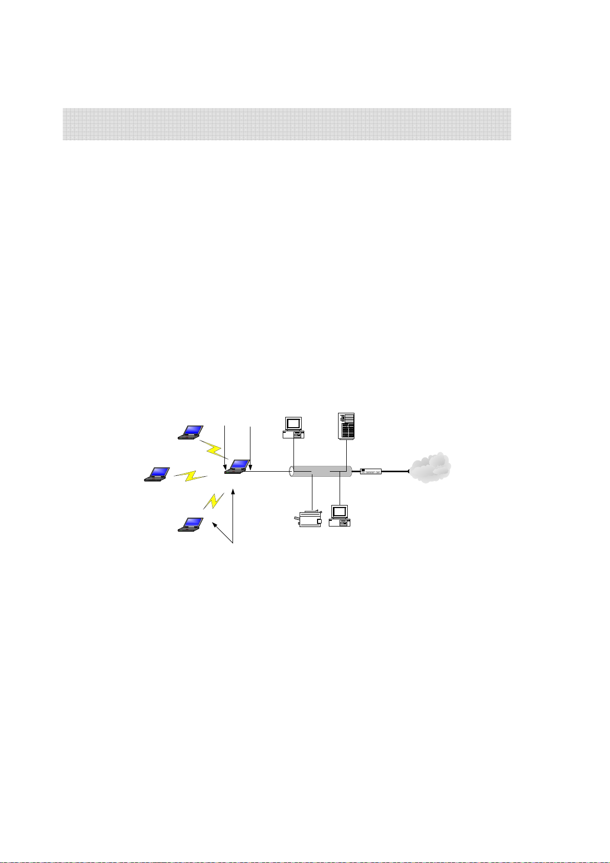
Bridge mode provides wireless AP connectivity to SoftGate clients, and bridges the existing
wired LAN segment(s) with the SoftGate host’s wireless LAN adapter. Typically, a bridge is
used to interconnect physical LAN segments on a network that already provides DHCP and
routing services.
In a typical use case, SoftGate will run on a PC to provide wireless AP functionality to client
devices. When run on a laptop, SoftGate is essentially a portable device that provides
wireless AP functionality on virtually any network. Because each network configuration may
be different, the SoftGate host will attempt to adapt to varying network configurations.
When a network is running a DHCP service you will not want to introduce a node that is also
running DHCP, therefore the SoftGate host should be configured in bridge mode if the LAN
or any LAN segment uses DHCP.
SoftGate in Bridge Mode
LAN Adapter and Wireless
Adapter Bridged
Desktop PC
Ethernet
Printer
Existing Subnet(s)
DHCP Server
Desktop PC
Firewall/Router
Internet
SoftGate Client
SoftGate Client
Quetec? SoftGate
Configured Laptop
SoftGate Client
SoftGate Clients and Host
Assigned IP by LAN DHCP
Server
Figure 3: SoftGate in Bridge Mode
40
Page 41
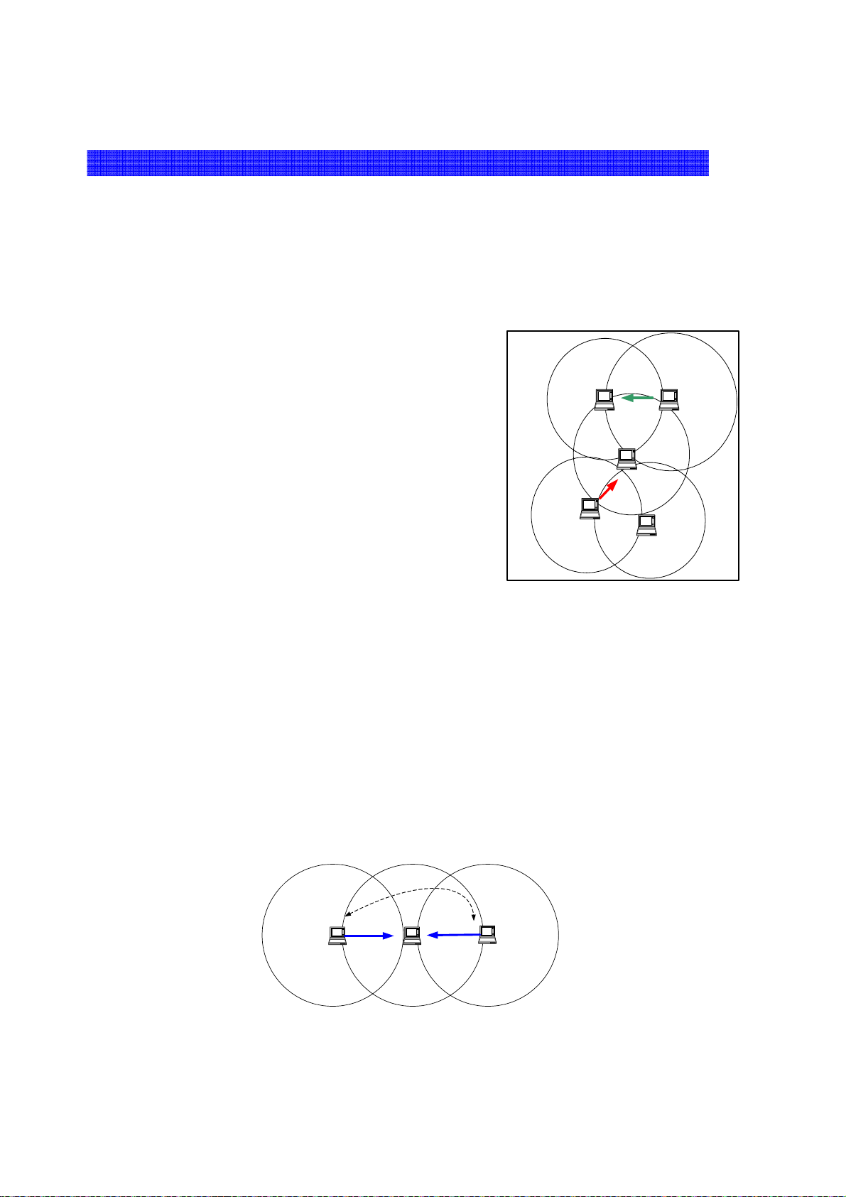
8.4 SoftGate more reliable & easier to use than Ad-Hoc networks
Ad-Hoc networks allow users to create a simple wireless network without the use of
an access point. However, there are several drawbacks when relying on ad-hoc
networks for wireless networking:
1: Ad-Hoc networks do not use the normal packet collision avoidance
technique (RTS/CTS) because of the “False Blocki ng ” pr oblem .
802.11 networks deploy a packet collision avoidance mechanism called RTS/CTS
(Ready to Send / Clear to Send). Although the mechanism works well in
infrastructure mode (or AP mode), the de-centralized nature of ad-hoc networks
renders them incompatib le with RTS/CTS. When used in conjunc tion with adhoc networks, RTS/CTS dramatically decreases overall throughput due to a
“false blocking” problem. Hence, most ad-hoc networks do not use the RTS/CTS
mechanism.
Figure (1) illustrates the “false blocking” problem. Node ‘B’ is attempting to
communicate with node ‘A’ so node ‘B’ therefore broadcasts an RTS packet,
which places node ‘C’ in a “blocked” mode. This prevents ‘C’ from attempt ing to
send packets while ‘A’ and ‘B’ is communicating, as suc h attempts to send woul d
interrupt their connection.
At the same time, node ‘D’ wants to communi c ate with node ‘C’ so node ‘D’
broadcasts an RTS packet. Node ‘D’ does not recei ve a C TS message from node
‘C’ because node ‘C’ has been blocked from sending packets by the RTS packet
that was broadcast by node ‘B.’ Node ‘D’ therefore enters a backoff period, and
its capacity to communicate has been hindered.
Thus, node ‘D’ is unnecessarily blocked from communication with node ‘C.’ There is no real channel contention between no des
‘C’ and ‘D,’ but the problem of “false blocking” thwarts the ir attempts to communicate. The problem of “fal se bl ocking” has
further implications. Node ‘E’ is also blocked from communicating when node ‘D’ sends its RTS packet, and so on.
Enters a backoff mode
because node c is
blocked.
D
Figure 1: False Blocking Problem
2. Because ad-hoc networks do not use RTS/CTS they are susceptible to
the “hidden node” problem, which increases the number of collisions in
the network.
Figure (2) shows that in an ad-hoc network, node ‘A’ cannot “hear” node ‘C’ because node ‘B’ is positioned between them, and
because in order to avoid the “false blocking” problem the RTS/CTS mechanism is not being used. Since nodes ‘A’ and ‘C’ are
“hidden” from each other and ca nnot hear each other, nothing pr events ‘A’ an d ‘C’ from transmitting to node ‘B’ simultaneously.
This simultaneous transmission results in collision. In fact, the number of packet collisions in ad-hoc networks rises
exponentially as nodes (computers) enter the network. Packet collisions force a sender to re-send packets, thus increasing
latency (the time that it takes a data packet to m ove across a network connection), and diminishing overall throughput.
A cant ear?C, Collision occurs
when both transmit to B
RTS
A B
Blocked
C
RTS
Blocked
E
?
A B
C
Figure 2: Blocked Nodes in Ad-Hoc Network
41
Page 42
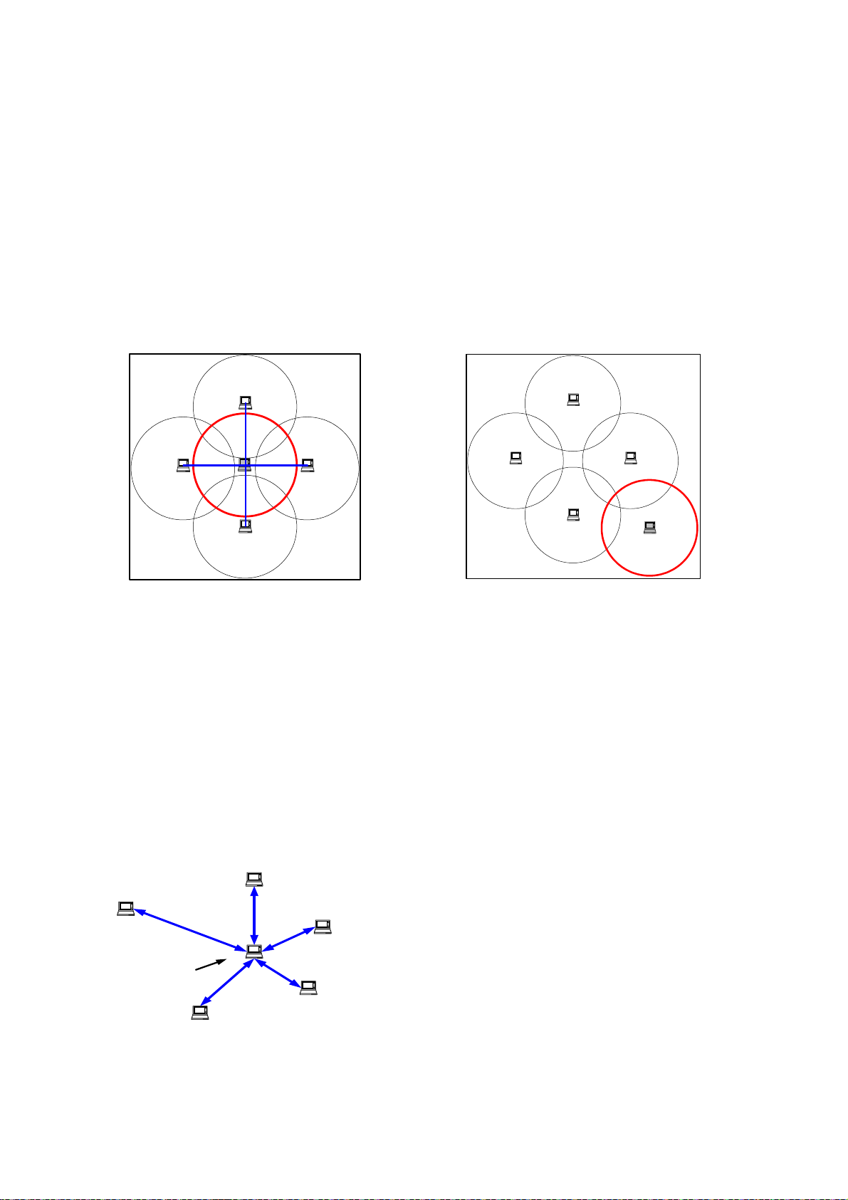
3. Ad-hoc networks are also susceptible to network breakdown due to
their decentralized nature.
Figure (3) shows the ad-hoc network functioning properly, as all clients are able to
communicate with each other. Figure (4) demonstrates how easy it is, though, for
an ad-hoc network to break down. Because the client node in the middle is
performing all of the routing for the other nodes, as soon as the client in the middle
exits the network or changes locations, the entire network breaks down.
Laptop computer
Laptop computer Laptop computer
Figure 3: Ad-Hoc network functioning properly
Laptop computer
Laptop computer
Laptop computer Laptop computer
Figure 4: Ad-Hoc network breaks down when central node
exits
Laptop computer
Laptop computer
Laptop computer
Conclusion: SoftGate is less susceptible to problems related to ad-hoc
networks.
Because SoftGate works as a true 802.11 wireless access point, client nodes do not
rely on each other for routing and traffic management. It is the responsibility of the
SoftGate host PC to centrally manage the wireless network. As long as client nodes
can “hear” the SoftGate host PC, they are virtually guaranteed a solid connection,
free from the unexpected drops or diminishing throughput that results from the
“hidden node” problem. In addition, it is easy for client nodes to “hear” the SoftGate
host PC because SoftGate functions as a true 802.11 access point, and is therefore
compatible with the RTS/CTS mechanism. Figure (5) shows SoftGate successfully
managing all of the client node traffic in the network.
Laptop computer
Laptop computer
Laptop computer
So ftA P
Enabled PC
Laptop computer
Laptop computer
Figure 5: SoftGate host is a true AP, centrally managing client traffic.
42
Page 43
QUETEC SoftGate Wireless
AP/Router
solution
(PCMCIA/PCI/USB interface)
中文繁體使用手冊
版本 C3.0 July 2004
www.quetec.net
Copyright 2004. All Rights Reserved.
Document Version: C3.0
All trademarks and trade names are the properties of their respective owners.
43
Page 44

著作權
任何全部或部份的出版品,不能以文章格式。內容意思及任何衍生作品,例如翻譯或改編性的文章,從1 9 7 6年
的美國著作權法規定,不能敘述廠商內容的法律規範。
COPYRIGHT
No part of this Publica tion may be reproduced, transmitted, transcr ibed, and stored in
retrieval System, or translate d into any language or computer language, in any form or
by any means, electronic, mechanical, magnetic, optical, chemical, manual or otherwise,
without the prior written permission of this company.
This company makes no representations or warranties, either expressed or im plie d, with
respect to the contents hereof and specifica lly disclaims any warranties, merchantability or
fitness for any particular purpose. Any software described in this manual is sold or licensed
"as is". Should the programs prove defective following their purchase, the buyer (and not this
company, its distributor, or its dealer) assumes the entire cost of all necessary servicing,
repair, and any incidental or consequential damages resulting from any defect in the software.
Further, this company reserves the right to revise this publication and to make changes from
time to time in the contents hereof without obligation to notify any person of such revision or
changes.
Copyright@2004 by QUETEC Inc., All rights reserved.
All brand and product names mentioned in this manual are trademarks and/or registered
Trademarks of their respective holders.
44
Page 45

FCC安全指示
本產品已經過<Class B 數位裝置>測試及嚴格要求。此限制按照F C C規則的1 5個部分。這些限制是為了在居住環
境中安裝任何設備,提供合理的保護,和對抗有害干擾而設計。若未按照指示正確的安裝或使用,此設備可能會產
生或散發射頻能源,並可能對電訊交通造成有害的干擾。但是,並不保證在特殊的安裝中,不會產生干擾。
Federal Communication Commission Interference Statement
This equipment has been tested and found to compl y with the limits for a Class B
digital device, pursuant to Part 15 of the FCC Rules. These limits are designed to
provide reasonable protection against harmful interferenc e in a residential installation.
This equipment generates, uses and can radiate ra dio frequency energy and, if not
installed and used in accordance with the instructions, may cause harmful
interference to radio communications. However, there is no guarantee that
interference will not occur in a particular installation. If this equipment does cause
harmful interference to radio or television reception, which can be determined by
turning the equipment off and on, the user is encouraged to try to correct the
interference by one of the following measures:
- Reorient or relocate the receiving antenna.
- Increase the separation between the equipment and receiver.
- Connect the equipment into an outlet on a circuit different from that
to which the receiver is connected.
- Consult the dealer or an experienced radio/TV technician for help.
FCC Caution: Any changes or modifications not expressly approved by the party
responsible for compliance could void the user's authority to operate this equipment.
This device complies with Part 15 of the FCC Rules. Operation is subject to the
following two conditions: (1) This device may not cause harmful interference, and (2)
this device must accept any interference received, including interference that may
cause undesired operation.
IMPORTANT NOTE:
FCC Radiation Exposure Statement:
This equipment complies with FCC radiation exposure limits set forth for an uncontrolled
environment.
This device complies with FCC RF Exposure limits set forth for an uncontrolled
environment, under 47 CFR 2.1093 paragraph (d)(2).
This transmitter must not be co-located or operating in conjunction with any other
antenna or transmitter.
This device was tested for typical by stander conditions that may occ ur during use.
To comply with FCC RF exposure requirements a minimum separation distance of
1.5cm must be maintained between the user’s body and the device, including the
antenna.
Remark: Wireless USB Dongle is limited in Ch1~Ch11 by specified fireware controled in
U.S.A.
45
Page 46
第一章 產品介紹
本章節提供對於
Quetec SoftGate
無線基地台/路由器之特性及規格總覽
.
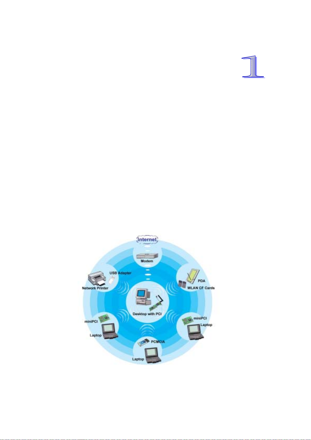
首先感謝您選購由Quetec SoftGate所研發生產的SoftGate無線網路方案,此產品能夠提
供您連接您的桌上型/筆記型電腦以及無線的區域網路設備。無需任何傳統纜線佈置或
無線存取點/路由器, Quetec SoftGate無線網路方案提供家庭或辦公室使用族群更具彈性
且更容易上手的無線資訊環境,您可以輕鬆且安全的進行訊息傳遞,網際網路應用或者是
與其他人進行如印表機等資源分享.同時,您不必求助於MIS的協助與維護更可省下一筆
龐大的硬體設備費用.無論是在家庭,公園或是辦公室內Quetec SoftGate無線網路解決方
案提供您無線空間的移動自由,讓您即刻進行訊息分享傳遞,享受無線寬頻上網的熱趣.
同時,您無需額外添購無線路由器或是無線存取點等昂貴的設備,因為SoftGate已經都幫
您準備好了!
Quetec SoftGate非常合適於一般家庭以及中小企業族群使用,可大幅節省硬體投資及網
路架設與維護費用,真正實現〝網路無限、無線網路〞的目標。
46
Page 47

1.1 QUETEC SoftGate 產品特性
1.2
z 超值四合一功能— 整合路由器、無線接入點、橋接器及無線網路卡等功能
z 符合 802.11b 無線傳輸標準
z 安裝/使用簡易— 自動偵測及設定無線接入點或無線使用端
z 安全/具彈性—支援 64/128-bit 加密設計,確保資料傳輸安全
1.2 QUETEC SoftGate 規格
標準
介面型態
多工模式
調制技術
安全機制
無線頻率
頻道
傳輸速率及調制方式
媒體存取協定
作業系統支持
LED 指示燈號
接收靈敏度
傳輸輸出
工作電壓
溫度
溼度
認證
產品保固
符合 IEEE802.11b 無線傳輸標準
PCMCIA, PCI, MiniPCI, USB
路由器, 無線基地台, 橋接器, 及無線網路卡
直接序列擴頻技術 DSSS
64/128bit WEP 加密; TKIP(Temporal Key Integrity Protocol)
2.412 ~ 2.462 GHz (美國,)
2.412 ~ 2.484 GHz (日本)
2.412 ~ 2.472 GHz (歐洲)
2.457 ~ 2.462 GHz (西班牙)
2.457 ~ 2.472 GHz (法國)
4 (法國), 2 (西班牙), 14 (日本), 13 (歐洲), 11 (美國,加拿大)
11Mbps: CCK
5.5Mbps: CCK
2Mbps: DQPSK
1Mbps:DBSK
CSMA/CA
Windows ME, 2000, XP
電源, 連結, 運行中
11Mbps@-84dBm
5.5Mbps@-86dBm
2Mbps@-91dBm
1Mbps@-93dBm
高於 17dBm
3.3/5V
運行 : -0°C to 55°C (32°F to 131°F)
儲存 : -5°C to 70°C (23°F to 158°F)
運行: 0% to 90% Non-Condensing
儲存: 0% to 90% Non-Condensing
FCC, CE, SAR
一年(硬體)
47
Page 48
1.3 QUETEC SoftGate 介面描述
QUETEC SoftGate AP/Router 無線方案提供數種介面型態:
z PCMCIA: 符合 PC card type II
z PCI: 符合 32 bit PCI 2.2
z USB: 符合 USB 1.0(2.0)
48
Page 49
第二章 硬體安裝總覽
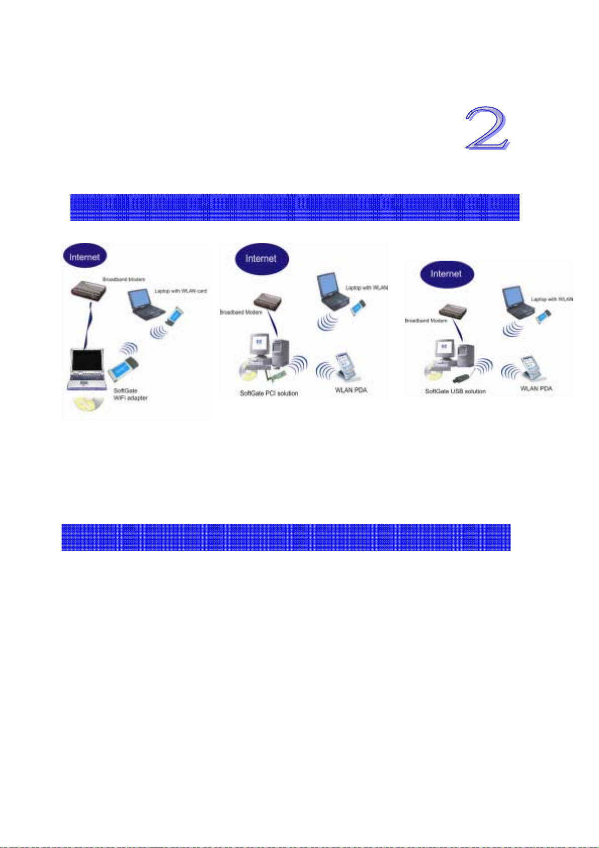
2.1 QUETEC SoftGate PCMCIA/PCI/USB 介面安裝圖示
*本安裝過程可能需要數分鐘完成.
注意:為了節省您寶貴的時間,在您開始安裝前,我們建議您先確認手邊有符合安裝所需要的正確設
備。包括SoftGate 無線介面裝置, 安裝光碟, 以及可供使用的電腦插槽..
2.2 安裝前確認事項
所欲安裝之機器必須配備 SoftGate 所支援之作業系統如視窗 ME/2000 或 XP.
預先確認所安裝之機器已可順利藉由微軟 IE 瀏覽器連結到網際網路.
假如所欲安裝之機器已先裝有其他無線網路卡,請在安裝 SoftGate 前先到開始: 控
制台:系統: 硬體: 裝置管理員: 網路介面卡, 選擇您正在使用的無線網路卡, 按滑鼠
右鍵, 關閉此一裝置運作.
49
Page 50
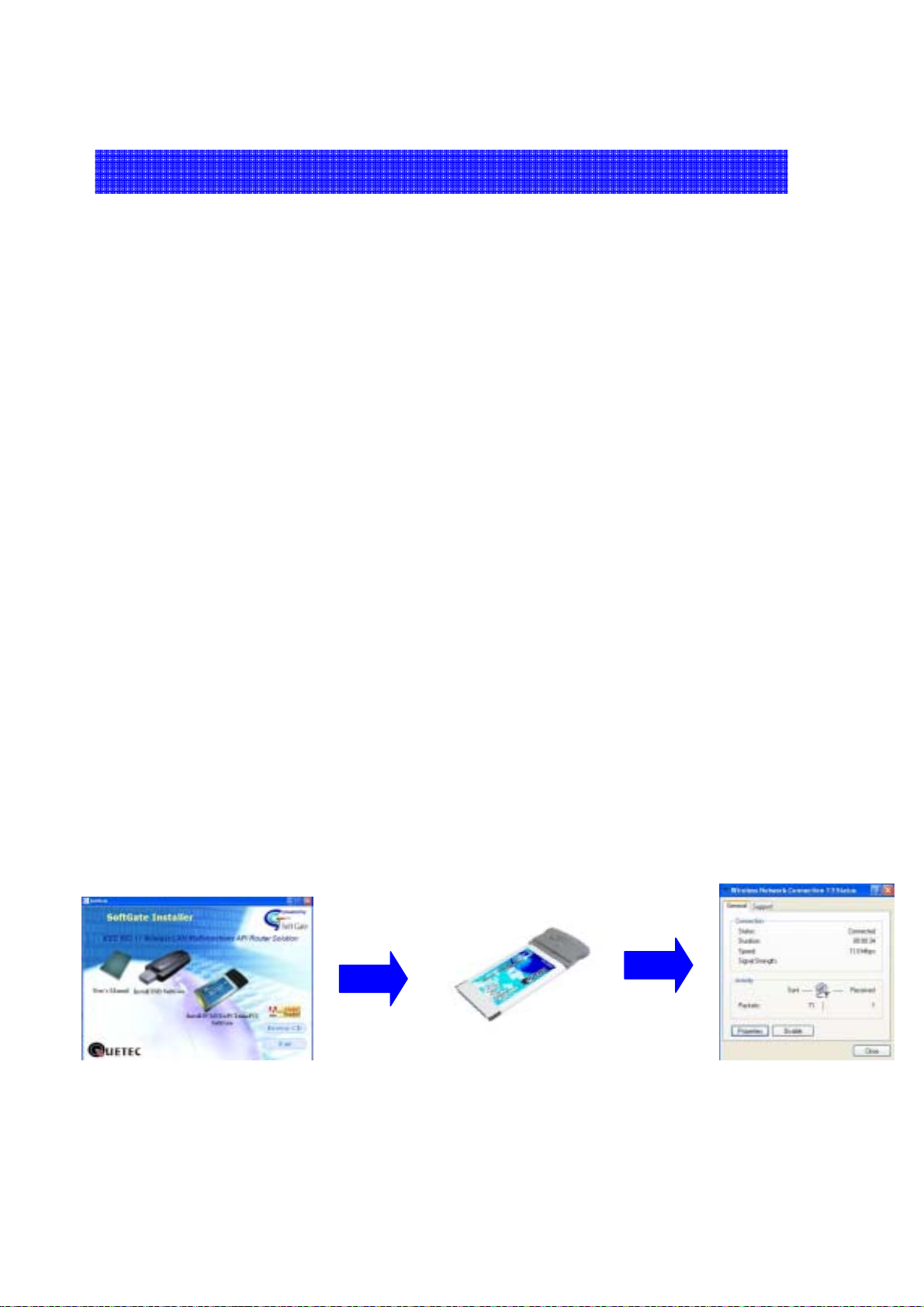
2.3 QUETEC SoftGate 快速安裝指南
一旦您已準備好進行安裝後, 請依下列步驟指示:
步驟一.
PCMCIA與USB介面: 先將SoftGate安裝光碟插入欲安裝之電腦光碟機中,自動安裝程
式將會啟動安裝精靈,接下來請在視窗中選擇你所要安裝的介面裝置圖形開始進行安裝
程式.
使用PCI介面: 首先關閉電源將PCI介面卡插入電腦PCI槽中後重新啟動電腦. 當系統出
現安裝新硬體精靈時, 請按取消選項後將SoftGate安裝光碟插入欲安裝之電腦光碟機
中,自動安裝程式將會啟動安裝精靈,接下來請在視窗中選擇你所要安裝的介面裝置圖
形開始進行安裝程式.
步驟二.
程式將自動執行安裝並設定所有的動作,當安裝精靈出現插入適合的介面卡裝置訊息時,
請依照安裝精靈的指示將介面卡插入指定的槽位中,按下一步繼續安裝動作.
步驟三.
繼續依照安裝精靈所要求的動作完成所有驅動程式及應用工具的安裝. 此時softGate將
會自動將你的電腦設定為無線基地台模式.
50
Page 51

第三章
QUETEC SoftGate
包裝內容
3.1 檢查包裝
在您開始安裝本產品之前,請先將您所購得之產品與以下的配件清單檢查比對,以確
定沒有任何配件有損壞或遺漏的清況發生。完整的產品配件應包含下列物件, 物件如
有任何短少,請速與原經銷單位聯絡,以確保您的權益:
包裝內容包含:
• 1 片 QUETEC SoftGate 無線網路介面卡(PCMCIA 或 PCI 或 USB)
• 1 片自動安裝光碟: 光碟內容如下
o SETUP.EXE: SoftGate 安裝程式
o Userguide: 使用手冊
• 一張快速安裝指南
• USB 包裝中另附一條 USB 纜線
51
Page 52

第四章 系統需求
請再次確認您欲安裝之電腦系統配備符合 SoftGate 最低之需求
:
• 電腦配備中央處理器需 PII 366MHz 或以上
• 128MB 記憶體或以上
• 微軟視窗 ME, 2000, XP
• 一組可以使用之插槽
• 光碟機
52
Page 53
第五章
此一章節說明將引領您基於微軟視窗 2000/XP 作業系統下進行 SoftGate 無線網路裝置
的安裝與設定.
注意
請勿先將
假如您先前曾安裝過舊版
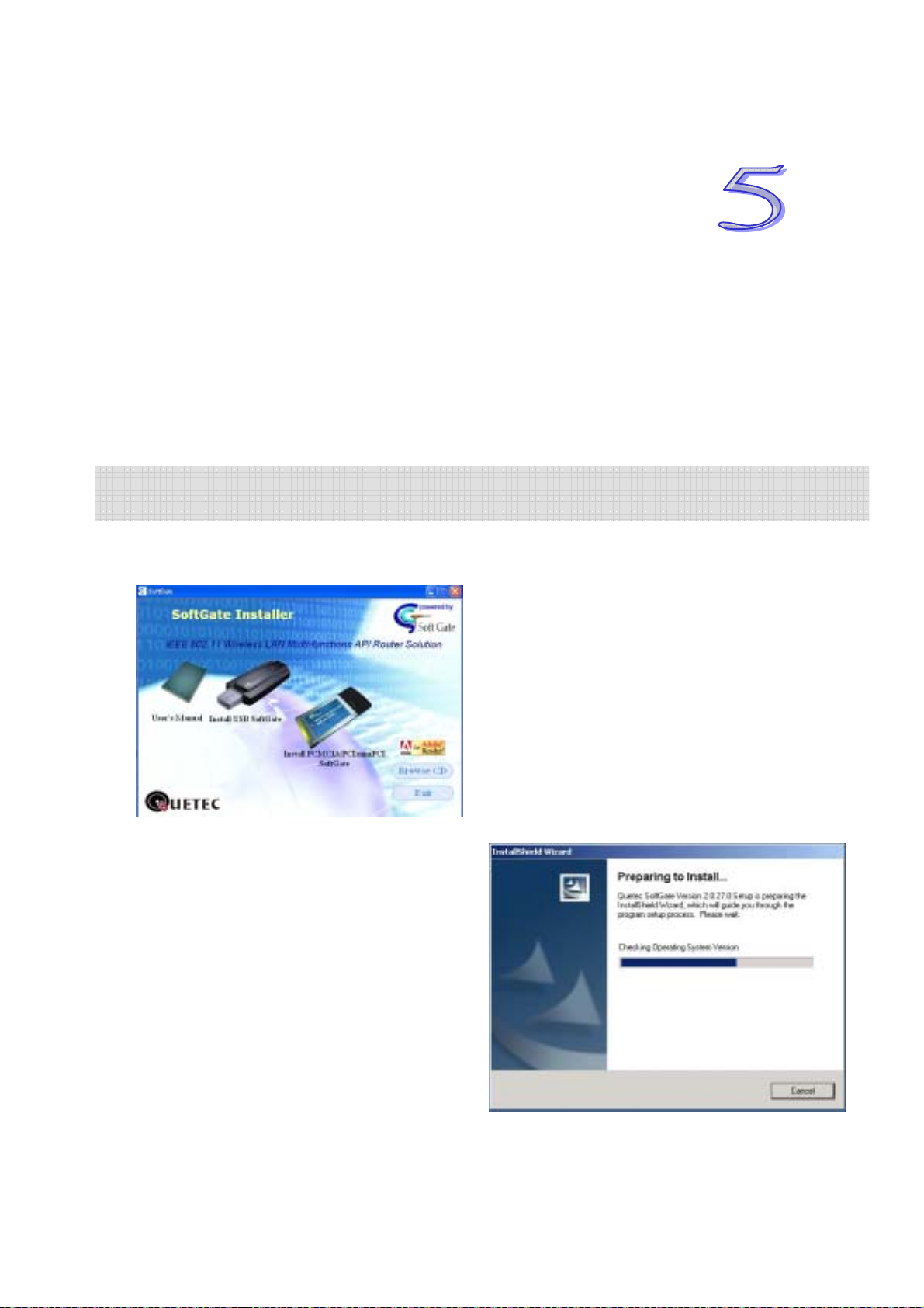
-將自動安裝光碟插入光碟機然後按下你所欲安裝之 SoftGate 裝置圖示, 會自動跳出安
裝歡迎畫面.
QUETEC SoftGate
.
PCMCIA
介面卡插入機器,請在接或安裝指示通知你後再將卡片插入
SoftGate
安裝程序說明
程式,請先將它移除後再開始進行安裝步驟
.
.
53
Page 54
-按下 “Next”鍵後,將會出現版權聲明畫面,
假如您同意版權內容請按下 “Yes”後繼續進行安裝步驟.如您不同意請按下“No”後離開
SoftGate安裝程式
-選擇您所要安裝的模式後按“Next”鍵,進行下一步動作.
(建議您選擇 “Express”模式進行首次安裝)
安裝過程中如您見到作業系統跳出此一硬體安裝警示視窗, 請按 “Yes” 進行下一個安裝步驟
54
Page 55

-安裝精靈將會自動執行安裝步驟,
-針對 PCMCIA/USB 介面安裝, 您會看到要求您插入 SoftGate 合適的裝置之對話視窗.
此時請將 PCMCIA/USB 插入您的電腦插槽, 安裝精靈將會自動繼續進行安裝步驟.
55
Page 56
-此時, SoftGate 安裝精靈將自動設定為無線基地台模式.
-在安裝過程後, 您將會看到下列訊息,
請按 “Next”鍵繼續安裝動作.
-請按”Finish”鍵完成安裝步驟.
您可以使用配備有其他無線網路卡的電腦進行連結,並測試 SoftGate 所提供的超強功能.
您應該同時也能在可用網路清單中發現 SoftGate.
56
Page 57
5.1 Windows ME 安裝重點提示
使用 SoftGate PCMCI A/USB 介面安裝
當您要在 Windows ME 作業系統下安裝 SoftGate, 在安裝過程中請勿將
PCMCIA/USB 介面卡插入電腦中.
請勿將 PCMCIA/USB 介面卡插入,直到 SoftGate 安裝程式要求你時再進行此一動作.
使用 SoftGate PCI 介面安裝
先關閉電源將 PCI 介面卡插入電腦 PCI 槽中,並確定卡片安裝妥當.
在看到 ”加入新硬體” 精靈視窗時,請關閉此一程式,並開始執行 SoftGate 的安裝
光碟.
安裝 Windows Me ICS 功能
在安裝好 SoftGate 之後欲將 SoftGate 設定在站台模式, 在 Windows ME 作業系統下您
必須手動設定 ICS 以便分享網際網路連接. 下列步驟將協助您如何進行 ICS設定. 請在
安裝妥 SoftGate 後依循下列指示.
7. 下列步驟將協助您在 Windows Me 下設定 ICS 模式.
• 選擇開始 >設定 > 控制台>新增/移除程式.
• 按下 Windows 安裝程式選項, Windows 將會自動發現所安裝之程式元件.
• 選擇並按下通訊圖示, 檢查 Internet 連線資源分享後按 OK 關閉通訊選項視窗,按 OK 關閉新增/移除程式視窗.
8. 此時將開始安裝 Microsoft ICS, 同時系統會啟動家用網路精靈. 請選擇下一步
開始安裝步驟.
57
Page 58
9. 因為 SoftGate 可以讓允許 PC 啟動網際網路分享之選項:你可以看到下列訊息
“Yes this computer uses the following”, 及 “A direct connection to an
ISP using the following device”.
10. 按下選項箭頭 (如下圖示) 將會出現可供分享之介面卡清單. 選擇您所使用來連
接寬頻數據機之網路介面卡後按 Next 鍵.
11. 當視窗出現”您是否要讓其他使用者透過您的電腦分享網際網路連線”訊息時
請按“Yes” 鍵. 此時下拉式選幕中出現可供其他使用者連接之介面卡訊息時,請
務必自清單中選擇 SoftGate 介面卡. 按 Next 鍵.
12. 此時將會出現”是否需要製作家庭網路安裝磁片”訊息視窗.您可以選擇”NO
“結束安裝步驟, 或者您可以進行製作家庭網路安裝磁片動作,讓其他電腦使用
此一安裝磁片.假如你選擇製作家庭網路安裝磁片請依照螢幕所指示之步驟進行
之.
注意: 請參考您的 Windows Me 使用手冊 或進入 http://support.microsoft.com 微軟技術支援網站獲
取更多相關訊息.
58
Page 59
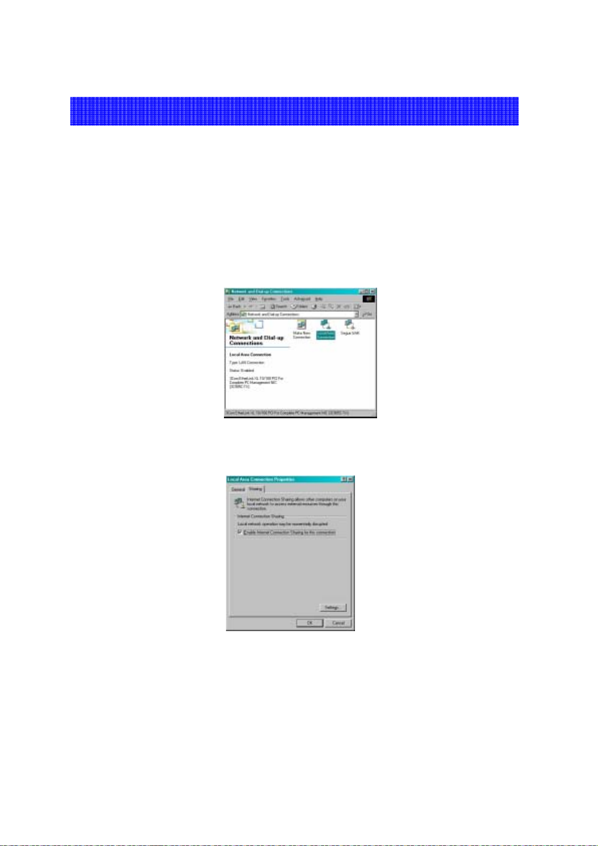
5.2 設定 Windows 2000 ICS 模式
在此非常強烈建議您升級您的 Windows 2000 作業系統到 Service Pack 4. 假如你無法
升級,那您必須完成安裝 SoftGate 後在 Windows 2000 系統下手動進行設定 ICS 設定.
5. 確認您的纜線數據機, DSL 或其他寬頻連接設備正常運作. 並確認你可以透過寬頻連
接設備聯結到網際網路.
6. 開啟連接寬頻數據機之網路介面卡內容選項後按下 "Sharing" 選項區.
• 操作步驟:在 桌面之"My Network Places" 圖示輕壓滑鼠右鍵, 選擇 "Properties",在"Local Area Connection"圖示上
按滑鼠右鍵,選擇"Properties"選項.
7. 勾選"Enable Internet Connection sharing for this connection" 選項啟動 ICS
模式.
8. 此時已設定為無線基地台的 SoftGate 將可讓連接上之無線網路用戶利用微軟之 ICS 模
式進行網際網路連結分享.
59
Page 60
第六章
6.1 總覽
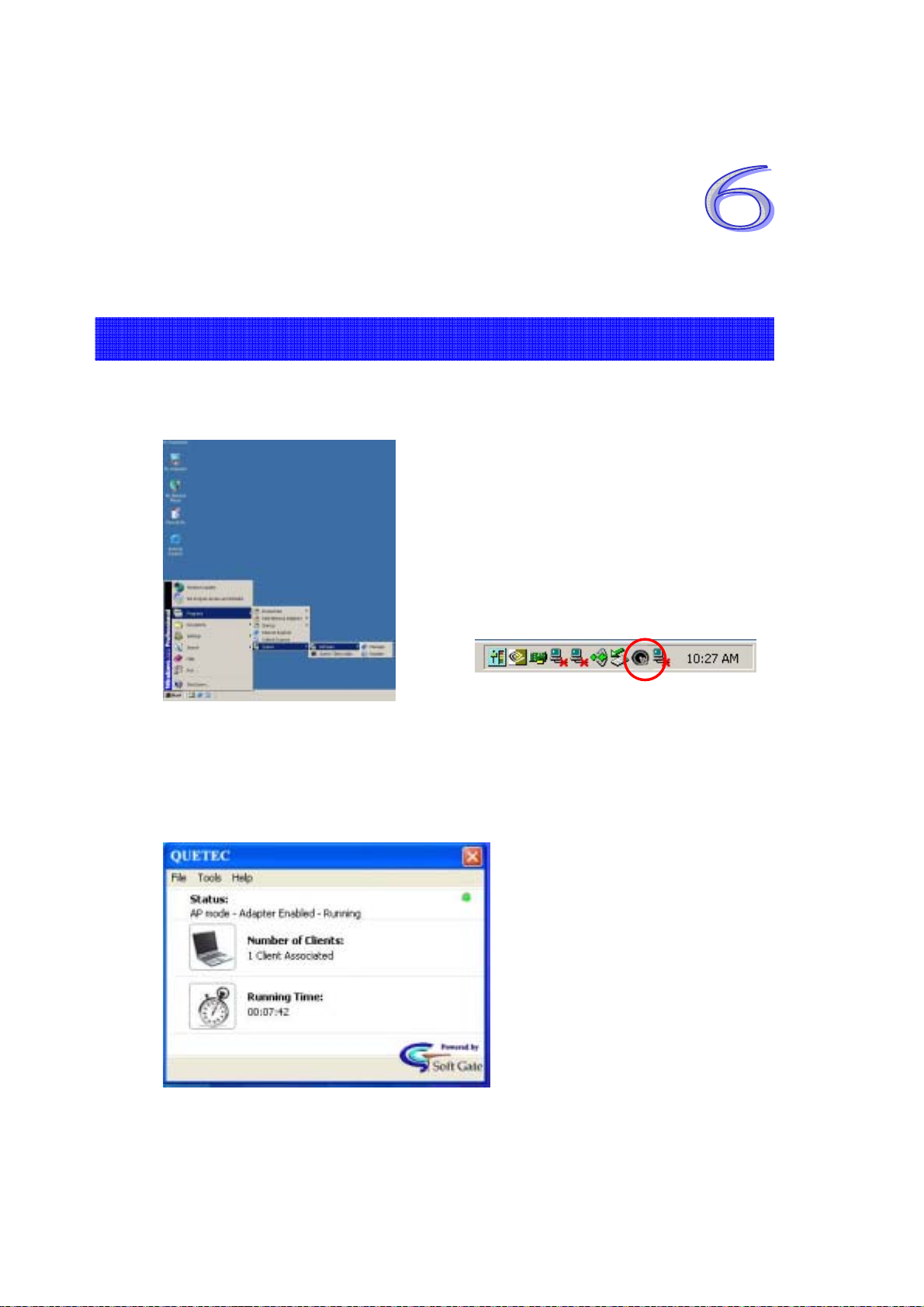
當成功安裝完 SoftGate 後,您可以在開始:所有程式集與工作列找到 QUETEC
SoftGate 圖示.
SoftGate 操作管理者主介面提供詳細操作功能:
• 右上角綠色燈號呈現閃爍狀態:代表 SoftGate 正在運行中
• 狀態: 顯示操作模式與介面卡狀態
• 用戶端數目: 顯示有多少用戶端連接到此一 SoftGate 上
• 執行時間:顯示 SoftGate 執行時間
QUETEC SoftGate
操作管理者
60
 Loading...