

Page 1
QX-280 Series Owner’s Manual
Page 2
1
Product Overview
The QX-280 Series Amplifiers are a high channel density, 1RU, high fidelity solution for high and low
impedance distributed audio systems.
Available as a single, two or four channel variant; the QX-280 Series is the ideal component for audio
visual installations, multi-channel systems, or distributed consumer/commercial applications. The transformerless speaker outputs deliver full range audio to all impedance loads from 4
Ω up to 70/100V systems.
Each amplifier channel has a switchable 80Hz 4th order Butterworth High-Pass filter located on the rear of
the amplifier, and a volume control that can be accessed directly from the front panel.
Each channel also includes a selectable Automatic Standby function. This is located on the rear of the
amplifier, and will mute that particular channel after 10mins of no audio signal presence. After 30mins that
channel will enter a sleep mode, which allows individual channels to draw less than 0.5W of mains power.
Safety Precautions
• Please read the instructions in this section carefully before use.
• Ensure all instructions in this manual are observed as all information contained within is very important.
• It is also highly recommended that this manual is retained for future reference.
Safety Symbol & Message Conventions
The safety symbols described are used in this manual to prevent bodily injury and property damage which
could result from mishandling. Before operating this product, please read this manual first, in full so you
that you are thoroughly aware of any risks.
Indicates a potentially hazardous situation which, if
mishandled, could result in serious personal injury or death.
WARNING
Page 3

2
• When cleaning the unit, ensure it has been
disconnected from any power source and
that only a dry cloth is used. Do not use any
aerosol or liquid based cleaners.
• Ensure all electronics are electronically
grounded (earthed) to a safety ground terminal
in order to avoid electric shock. Do not ground
any device to a gas pipe as this may result in
fire.
• Servicing of all electronics should only be
carried out by a certified Quest technician.
Please consult your original place of purchase
to find the location of your nearest Quest
service centre.
• When installing amplifiers and\or other
electronics only use the hardware specifically
designed for this product.
• Do not expose the unit to any moisture
whether rain, water or other liquids. Exposure
to moisture could result in damage to internal
components or electrocution\circuit failure.
• Do not cut, kink, otherwise damage or modify
speaker cable. Ensure a speaker cable with
a core diameter of at least 1.5mm is used for
correct performance.
• Do not install or place speaker cables or
this device near heaters, high traffic areas or
any area where the cables or device can be
damaged.
• Avoid installing or mounting speaker boxes,
amplifiers, electronics or cabling in unstable
locations.
• In the event of storms and\or lightning, ensure
all devices are disconnected from mains
power in order to prevent damage to any of
the units in the system.
General Caution
Page 4
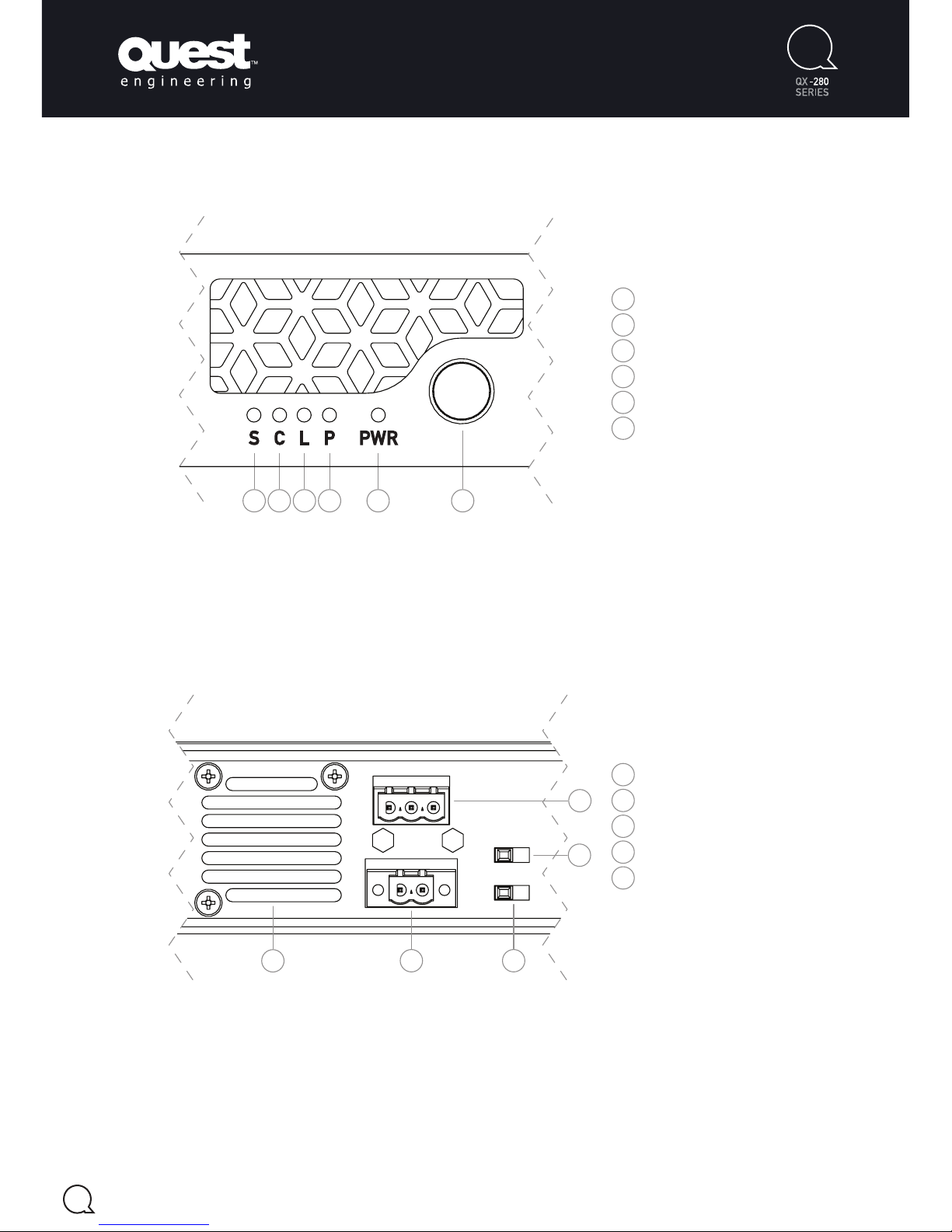
3
Rear Panel Connections & Controls (per channel)
Front Panel Controls (per channel)
Audio Signal Indicator
Amplifier Clip Indicator
Limiter Active Indicator
Amplifier Protect Indicator
Amplifier Power Indicator
Rotary Gain Control
1
2
3
4
5
6
1
2 3 4 5 6
Audio Signal Indicator
Amplifier Clip Indicator
Limiter Active Indicator
Amplifier Protect Indicator
Amplifier Power Indicator
Rotary Gain Control
1
2
3
4
5
6
Cooling Fan Exhaust
Speaker Output Connector
80Hz High Pass Filter Enable
Auto Standby Enable
Audio Signal Input Connector
1
2
3
4
5
1
1
2
3
4
5
2 3 4 5 6
Figure 1.00
Figure 1.01
Page 5
4
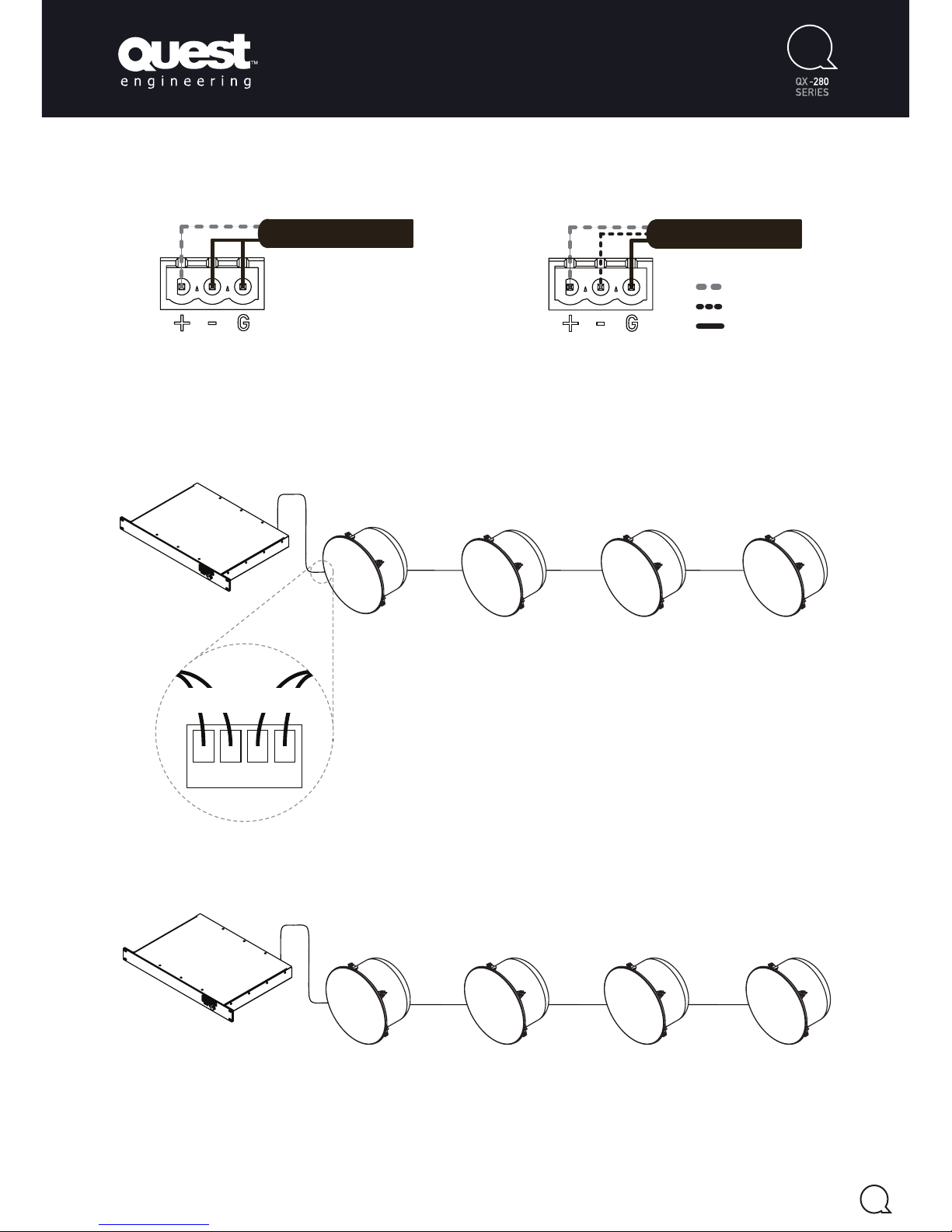
Input Signal Wiring Examples
Amplifier Wiring Examples
70/100V System (example shows 30W tap settings)
Parallel Wiring
+ Hot
- Cold
Ground
Unbalanced Wiring
Balanced Wiring
+ Hot
- Cold
Ground
Balanced Wiring
16Ω 16Ω 16Ω 16Ω
+ - +-
16Ω 16Ω 16Ω 16Ω
+ - +-
from
amplifier
to
speakers
16Ω 16Ω 16Ω 16Ω
+ - +-
16Ω 16Ω 16Ω 16Ω
+ - +-
+ Hot
- Cold
Ground
Unbalanced Wiring Balanced Wiring
16Ω 16Ω 16Ω 16Ω
+ - +-
16Ω 16Ω 16Ω 16Ω
+ - +-
from
amplifier
to
speakers
16Ω 16Ω 16Ω 16Ω
+ - +-
16Ω 16Ω 16Ω 16Ω
+ - +-
30W 30W 30W 30W
+ Hot
- Cold
Ground
Unbalanced Wiring Balanced Wiring
Connector wiring is the
same for both examples
Total Amplifier Load 120W
(Not including other parasitic loading, always allow amplifier headroom)
Total Amplifier Load 4Ω
Figure 2.00
Figure 3.00
Figure 3.01
Figure 2.01
Page 6
5
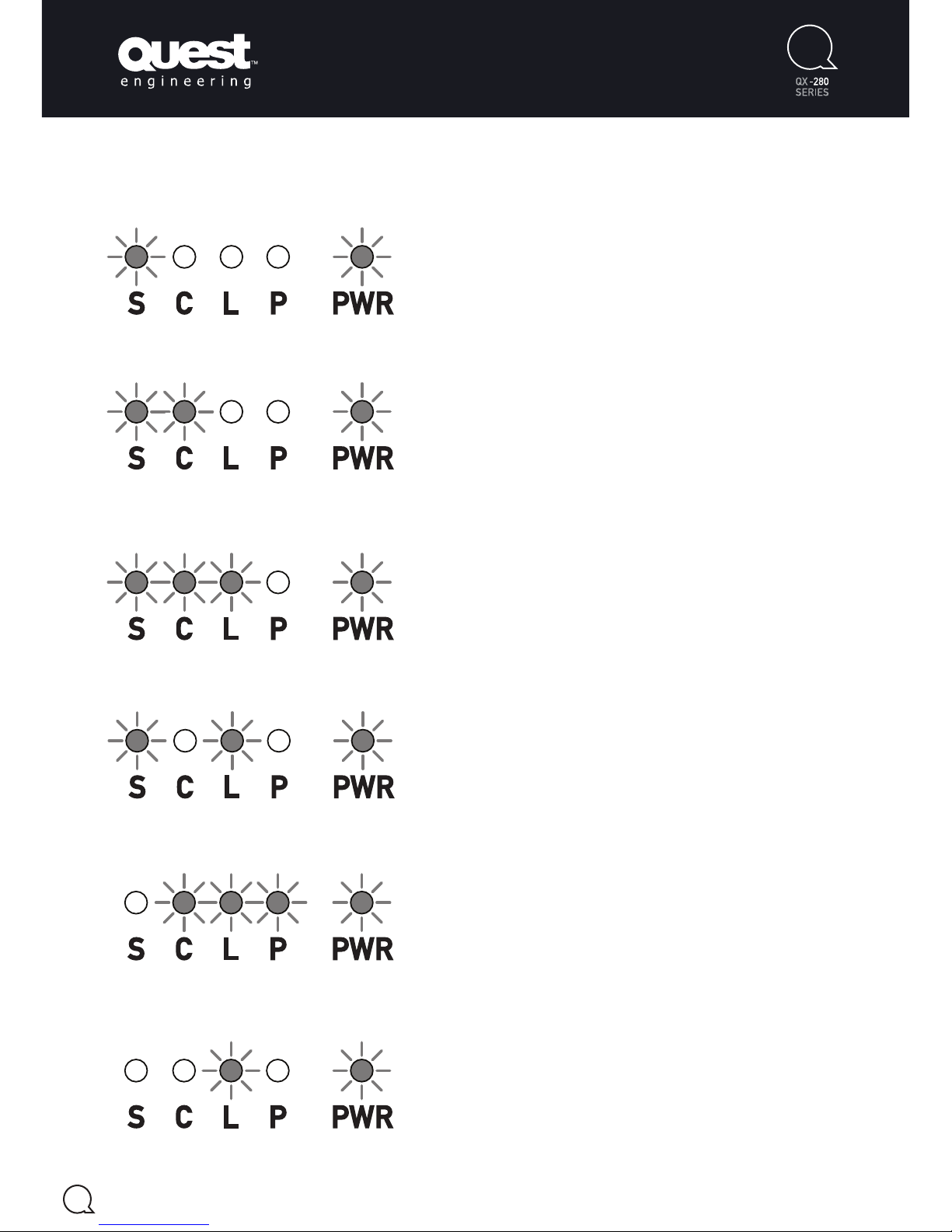
Front Panel LED Indicators
Audio Signal is Present
This LED will illuminate when the amplifier detects
an audio signal.
Amplifier Channel is Clipping
If the amplifier is clipping, this LED will illuminate.
Limiter is Active
When the amplifier reaches the point of clipping,
the limiter LED will illuminate. This indicates the
limiter circuit is reducing the audio input signal, in an
attempt to stop the signal from clipping.
Amplifier Channel is Thermally Limiting
If the amplifier reaches a critical temperature level,
the limiter circuit will activate in an attempt to keep
the amplifier temperature within its limits.
Amplifier Channel is Muted
If Auto-Standby is enabled via the switch on the rear
panel, the amplifier will enter a mute state after no
audio signal has been present for ~10mins.
Amplifier Channel is in Standby Mode
If Auto-Standby is enabled via the switch on the rear
panel, the amplifier will enter a standby state after
no audio signal has been present for ~30mins. This
mode enables that respective amplifier channel to
draw <0.5W of mains consumption during a standby
state.
Figure 4.00
Figure 4.01
Figure 4.02
Figure 4.03
Figure 4.04
Figure 4.05
Page 7
* All specifications were measured at 240VAC
** Quest Engineering reserves the right to make changes in specifications, or products without prior notice.
*** The figures shown above are ‘real world’, usable specifications and are conservative as a result. Quest Engineering does
not believe in portraying misleading or exaggerated specifications.
6
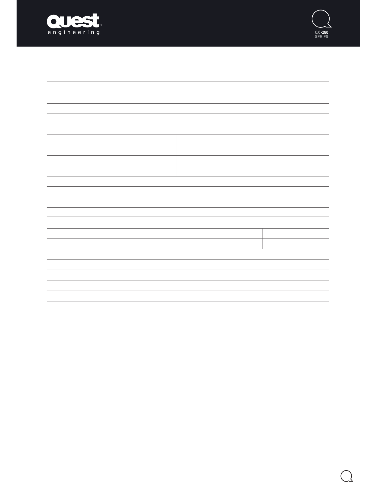
Technical Specifications *per channel
Peak Output Current 25A
THD+N
(1kHz @ 1W / 1kHz Rated Power) 0.022% / 0.015%
Dynamic Range 119dBA
Output Resistance
(1kHz) 43.6mΩ
Peak Output Voltage
(unloaded) ±140V
Power Output 4Ω 280W
8Ω 245W
70V 250W
100V 240W
DC Offset ±7mV
Frequency Response ±0.1dB 20Hz - 20kHz
(1st order 22kHz LPF)
Voltage Gain (@ 1kHz) 32dB
Mechanical Specifications
Net Weight QX1280 - 4.5kg QX2280 - 4.9kg QX4280 - 5.7kg
Gross Weight QX1280 - 7.1kg QX2280 - 7.5kg QX4280 - 8.3kg
Dimensions
(H x W x D) 44 x 485 x 304mm
Input Connections 3-Way 5.08mm Captive Screw Connector
Output Connections 2-Way 5.08mm Locking Captive Screw Connector
Mains Power Connection IEC C14
Mains Input Voltage 85 - 265VAC
Page 8

www.questengineering.com.au
Register Your Product
Thank you for choosing Quest. Please take the
time to complete your product registration.
Registering your Quest Engineering product will:
• CONFIRM YOUR WARRANTY
• REGISTER YOUR PRODUCT
• PROTECT YOUR NEW PRODUCT
REGISTER ONLINE:
www.questengineering.com.au/registration
For spare parts and service, contact your local
authorised Quest Dealer.
 Loading...