

Page 1
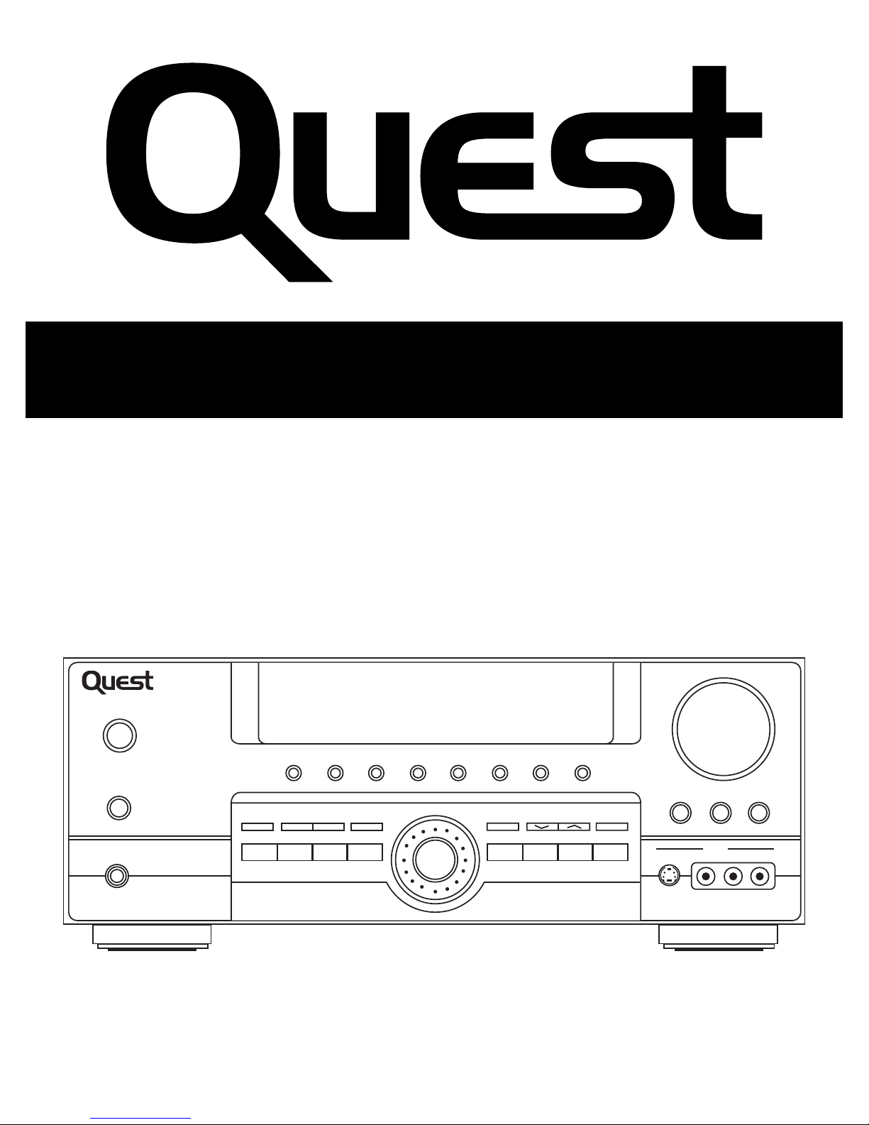
DOLBY DIGITAL
SURROUND RECEIVER
INSTRUCTIONAL MANUAL
QSR5000
DOLBY DIGITAL SURROUND RECEIVER
REMOTE
SENSOR
POWER (STANDBY)
STADIUM CONCERT THEATER CHURCH ARENA CLUB DSP OFF NIGHT
MUTE
PHONES
SURR. MODE TEST/SET UPPRESET EQ BY PASS
DVD
SAT VCR 1
6 CH. P. SCANTUNING
VCR 2 CD
MODE/
SET
FM/AM TV TAPE
BASS
VCR 2
VIDEO
S-VIDEO L AUDIO R
VOLUME
TREBLE
LEVEL
Page 2
FEDERAL COMMUNICATIONS COMMISSION (FCC) INFORMATION
This equipment has been tested and found to comply with the limits for a Class B digital device pursuant to
Part 15 of the FCC Rules These limits are designed to provide reasonable protection against harmful
interference in a residential installation. This equipment generates, uses and radiates radio frequency
energy and, if not installed and used in accordance with the instructionj may cause harmful interference to
radio communications. However, there is po guarantee that interference will not occur in a particular
installation " in accordance with FCC requirements, changes or modifications not expressly approved by
Total Technolgoy Company could void the user's authority to operate this product This device generates and
uses radio frequency (RF) energy, and if not installed and used properly, this equipment may cause
interference to radio and television reception. If this equipment does cause interference to radio or
television reception (which you can determine by unplugging the unit), try to correct the interference by one
or more of the following measures:
• Re-orient the receiving antenna (that is, the antenna for the radio or television that is "receiving" the
interference).
• Move the unit away from the equipment that is receiving interference.
• Plug the unit into a different wall outlet so that the unit and the equipment receiving interference are on
different branch circuits.
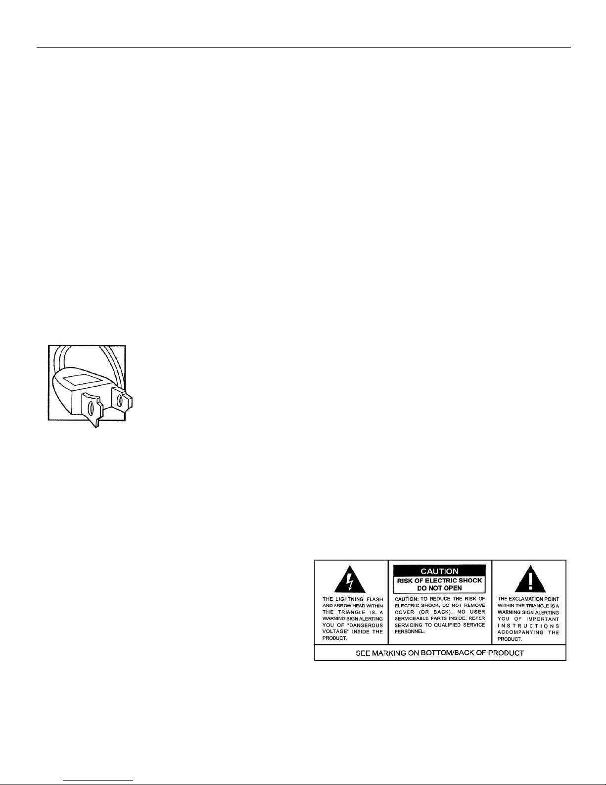
The AC power plug is polarized (one blade is wider than the other) and only fits into
AC power outlets one way. If the plug won’t go into the outlet completely, turn the plug
over and try to insert it the other way. If it still won’t fit, contact a qualified electrician
to change the outlet, or use a different one.
Do not attempt to bypass this safety feature.
CAUTION: TO PREVENT ELECTRIC SHOCK, MATCH WIDE BLADE OF PLUG TO WIDE SLOT, FULLY INSERT.
FOR YOUR SAFETY
FOR YOUR RECORDS
In the event that service should be required, you may need both the model number and the serial number.
In the space below, record the date and place of purchase, and the serial number:
Model No.
Remote Control No.
Date of Purchase
Place of Purchase
Serial No.
SERVICE INFORMATION
This product should be serviced only by those specially trained in appropriate servicing techniques. For
instructions on how to obtain service, refer to the warranty included in this manual.
Page 3

GETTING STARTED
Unpacking the Receiver.......................................................................................................................2
Inserting Batteries into Remote Control.................................................................................................3
Set Up and Maintenance of the Receiver................................................................................................3
Protect your Components from Overheating..........................................................................................3
Connecting to Audio-Visual Components..............................................................................................4
Digital Connection..............................................................................................................................5
Connecting Antennas..........................................................................................................................5
Connecting the Speakers.....................................................................................................................6
Connecting the Subwoofer...................................................................................................................6
Positioning your Speaker.....................................................................................................................7
Front Speaker Placement.....................................................................................................................7
Advanced Setting...............................................................................................................................7
Preferred Surround Placement..............................................................................................................8
Advanced Surround Setting.................................................................................................................8
Test Tone/Channel Balance..................................................................................................................8
Connecting for Power..........................................................................................................................8
Using Headphones.............................................................................................................................8
OPERATING YOUR RECEIVER
Receiver Controls................................................................................................................................9
Your Remote Control.........................................................................................................................10
Display............................................................................................................................................11
Switching On/Off............................................................................................................................12
Selection of Audio/Video Source.......................................................................................................12
Using the Receiver to Play a Source....................................................................................................13
Operating the Radio.........................................................................................................................14
ADVANCED SOUND CONTROL
Sound Enhancement Systems.............................................................................................................17
Fine Setting of Components...............................................................................................................18
CARE AND MAINTENANCE
Receiver/Tuner Operation.................................................................................................................20
Remote Control Operation................................................................................................................20
General...........................................................................................................................................20
Cleaning the Exterior.........................................................................................................................20
Equipment Specifications...................................................................................................................20
LIMITED WARRANTY
Limited Warranty..............................................................................................................................21
Page 4
GETTING STARTED
2
UNPACKING THE RECEIVER
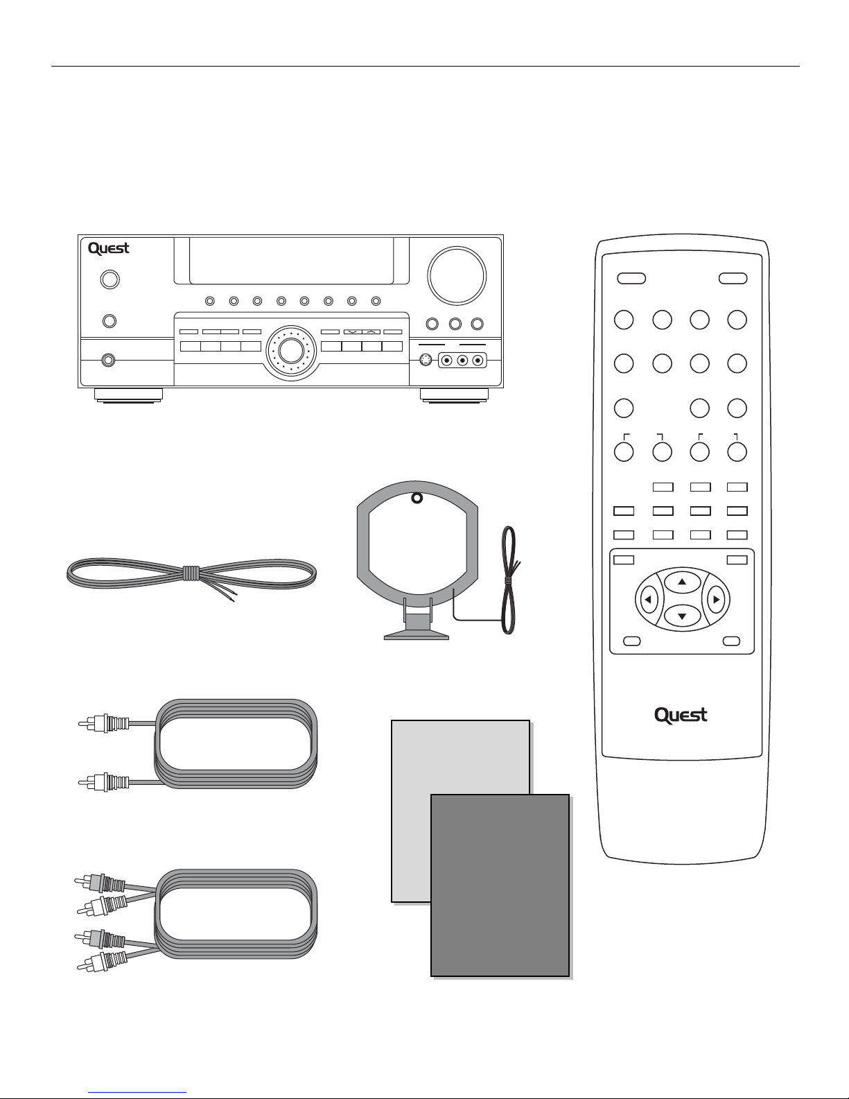
You should have the following items:
One Quest QSR5000 receiver unit
One external FM Dipole antenna
One external AM loop antenna
One audio cable (two wires) with red
and white RCA connectors
One video cable (single wire) with
white RCA connectors
One remote control
SAFETY
LEAFLET
USER
MANUAL
• One instruction book
• One safety leaflet
DOLBY DIGITAL SURROUND RECEIVER
VCR 2
MODE/
SET
POWER (STANDBY)
MUTE
PHONES
REMOTE
SENSOR
STADIUM CONCERT THEATER CHURCH ARENA CLUB DSP OFF NIGHT
SURR. MODE TEST/SET UPPRESET EQ BY PASS
DVD
SAT VCR 1
6 CH. P. SCANTUNING
CD
FM/AM TV TAPE
VOLUME
BASS
TREBLE
VCR 2
VIDEO
S-VIDEO L AUDIO R
LEVEL
POWER
SAT DVD/6CH. VCR 1 VCR 2
CD TAPE TV TUNER
PRESET EQ. SLEEP DIMMER
TUNING CHANNEL
12
4563
8907
VOLUME
SURR. MODE LEVEL
MUTE
MEMORY
TESTDIGITAL
QSR5000
REMOTE CONTROL UNIT
Page 5
GETTING STARTED
3
INSERTING BATTERIES INTO THE REMOTE
Insert two "AAA" batteries according to the + and -signs on the battery compartment. To use the remote
control, point it directly at your receiver.
SET UP AND MAINTENANCE OF THE RECEIVER
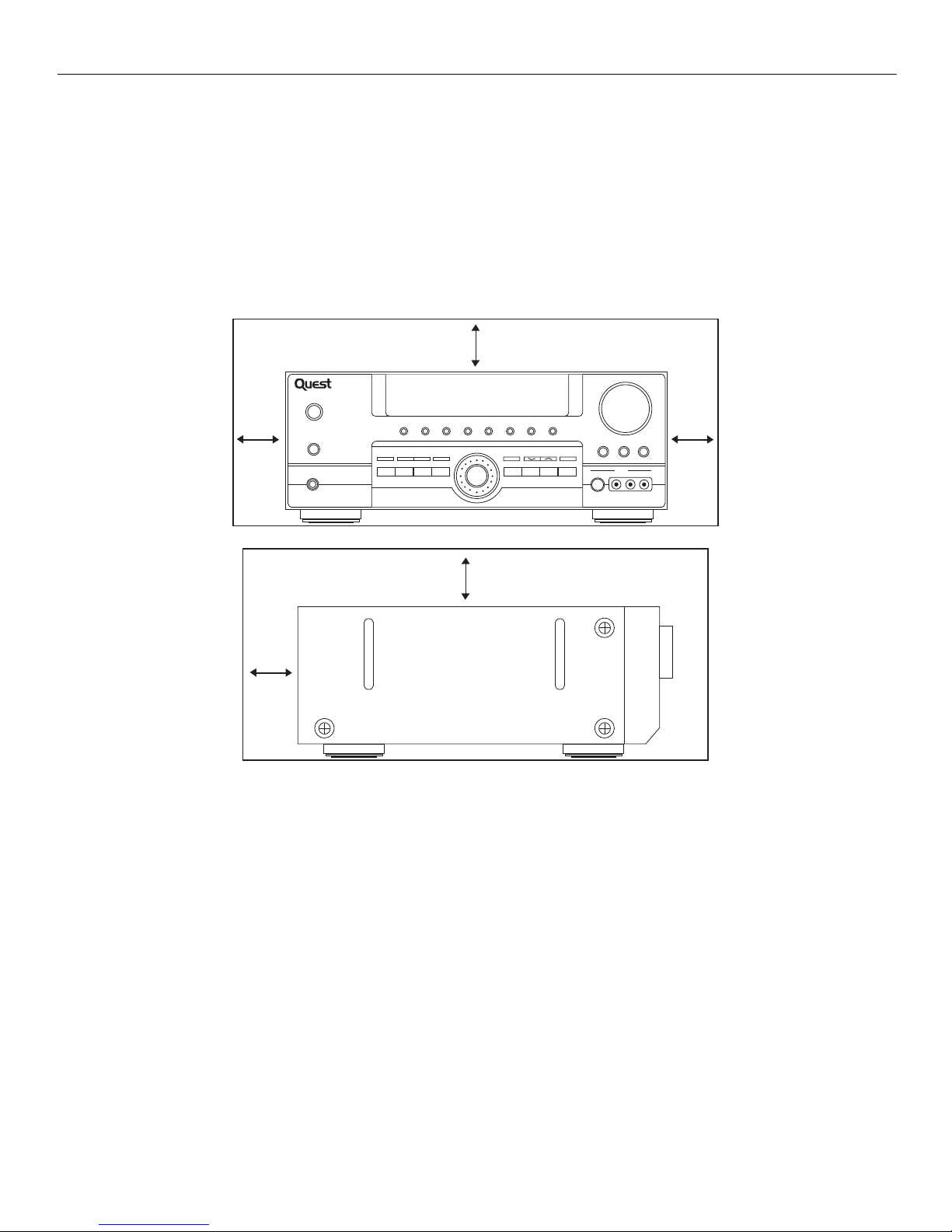
• Provide spaces for sufficient ventilation as indicated:
• Do not connect the AC power cords until all connections are completed.
• Do not use your receiver immediately after transferring it from a cold place to a warm place; there is risk
of condensation.
• Do not expose your receiver to water and excessively high temperatures.
• After having disconnected your receiver, clean it with a soft cloth, or with a slightly damp leather
chamois. Never use strong solvents.
PROTECT YOUR COMPONENTS FROM OVERHEATING
• Do not block ventilation holes in any component. Arrange the components so that air can circulate freely.
• Do not stack components directly on top of each other.
• Allow adequate ventilation when placing your components in a stand.
• Place your amplifier near the top shelf of the stand so heated air rising from it will not affect other
components. If you have a satellite receiver, you shoud place it on the top shelf.
10cm/4"
VOLUME
TREBLE
BASS
VCR 2
VIDEO
S-VIDEO L AUDIO R
10cm/4"10cm/4"
LEVEL
POWER (STANDBY)
MUTE
PHONES
DOLBY DIGITAL SURROUND RECEIVER
REMOTE
SENSOR
STADIUM CONCERT THEATER CHURCH ARENA CLUB DSP OFF NIGHT
SURR. MODE TEST/SET UPPRESET EQ BY PASS
DVD
SAT VCR 1
VCR 2 CD
MODE/
SET
6 CH. P. SCANTUNING
FM/AM TV TAPE
10cm/4"
5cm/2"
Page 6
GETTING STARTED
4
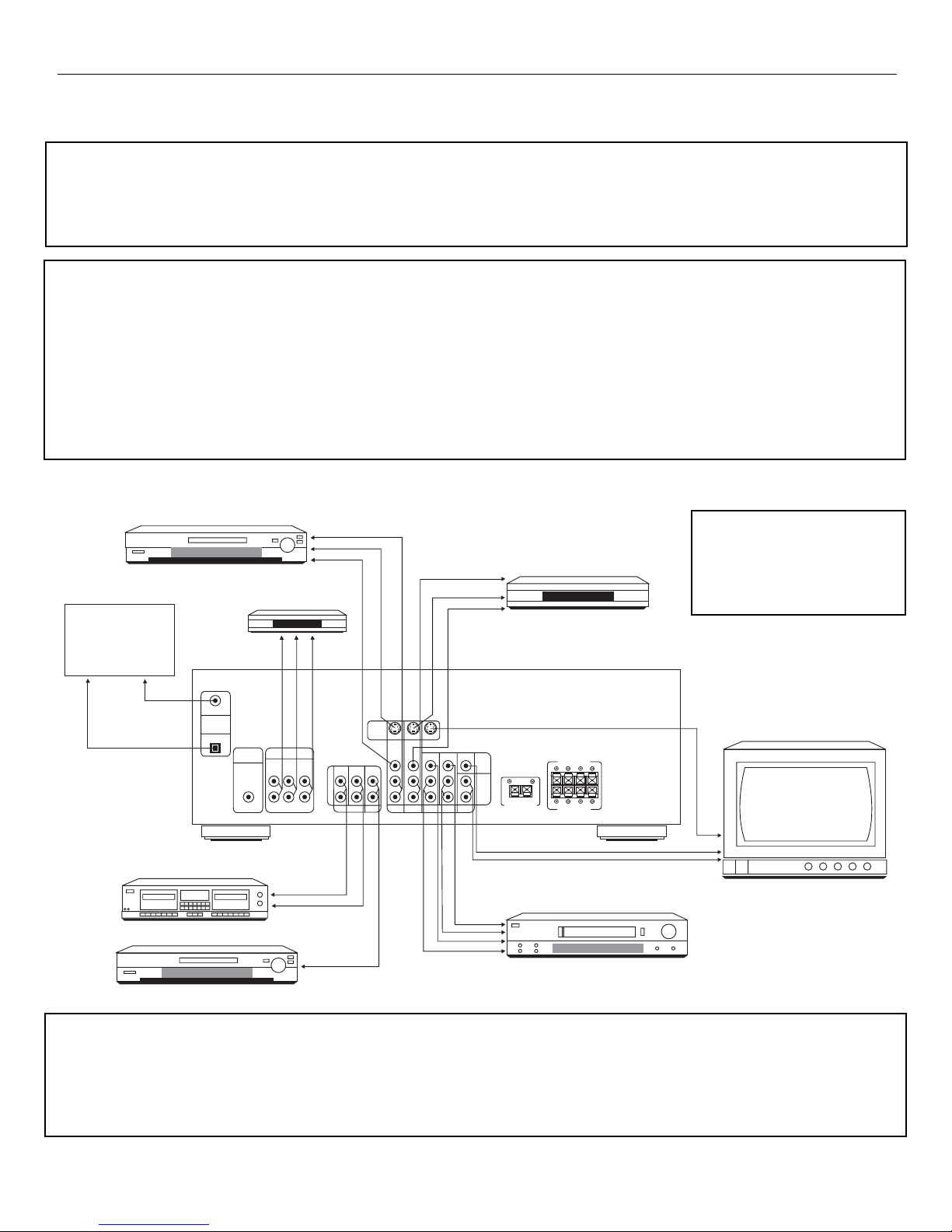
CONNECTING TO AUDIO-VISUAL COMPONENTS
If your video component has a S-Video jack included you can make use of it to enjoy enhanced video quality by connecting it to
the relevant S-Video jack at the rear side of the receiver. One video cable is needed for each component. When S-Video cable
is used, composite video (yellow RCA connector) cable must also be connected for VCR recording.
NOTE: Before plugging in the optical cable or S-Video cable, make sure to match the shape of the plug and jack, otherwise,
you will not be able to plug in completely.
If you have a SAT receiver, DVD player, or CD player with a digital ouput, you can make use of an optical digital connecting
cord (not supplied) or coaxial digital connecting cord (not supplied) to carry the audio portion of the signal and enjoy Dolby
DigitaI sound quality. One optical or coaxial cable is needed for each SAT receiver, DVD player or CD player. When optical or
coaxial cable is used, the analog audio cables are still needed if recording through a tape or VCR is desired. This receiver
provides one optical and one coaxial digital input for the connection of your components. Please connect your components (e.g.
DVD, SAT, or CD) to the appropriate digital inputs and press FUNCTION and then rotate MULTIJOG to match your connection.
NOTE: Optical and coax cables carry only the audio portion of the signal. A video connection must also be established for a
SAT receiver and DVD player. S-Video provides the best connection for the video portion of the signal. Composite video
(yellow RCA connector) can also be used. It is important that the same type of cable (S-Video or composite) that is connected
from the Home Theater to the TV is used to connect the SAT receiver or DVD player to the Home Theater.
If your CD player is equipped with digital optical jacks, use of optical cable is preferred. What you need is just one more
optical digital connecting cord (not supplied). Plug it in the digital input jack of the receiver and select OPTICAL on the receiver
setting (see details on pg.18 chapter “Input Signal Setting”). You can enjoy better sound quality brought to you by the optical
cable. When optical cable is used, analog cables are still needed for recording to tape output.
NOTE: This receiver has one digital optical jack only. Be sure that such connection does not prevent optical cable connection of
other components (e.g. DVD & SAT)
NOTE: If you have a video
camera, video game
machine, or an extra VCR,
connect it to VCR 2 jack at the
front of the receiver.
Connect components capable of
outputting Dolby Digital (e.g. DVD
or SAT) or standard PCM (CD)
format digital signals. Read
section on “Input Signal Setting”
under “Advanced Sound Control”
carefully to adjust the matching
input settings.
TAPE DECK
CD PLAYER
DVD
MULTI-CHANNEL DECODER
e.g. DTS
COAXIAL
DIGITAL
IN
OPTICAL
SUBWOOFER
OUT
6 CHANNELS OUT
6CH. DIRECT INPUT
FL SL CENTER
FR FL SUB
to LINE OUT
(TAPE DECK)
to LINE IN
(TAPE DECK)
to AUDIO OUT (DVD)
to VIDEO OUT (DVD)
IN OUT IN
L
R
TAPE
AUDIO OUT
(CD PLAYER)
to AUDIO OUT (SAT)
S-VIDEO
CD DVD SAT VCR 1
MON.OUT
IN OUT MON.OUT
AUDIO OUT (VCR)
to VIDEOOUT (SAT)
TV
VIDEO IN (VCR)
AUDIO IN (VCR)
VIDEO OUT (VCR)
SATELLITE
to S-VIDEO IN (TV)
VIDEO
L
AUDIO
R
CENTER SPEAKER(8Ω)
MAIN SPEAKERS(8Ω)
RL
RL
REAR SPEAKERS(8Ω)
to VIDEO IN (TV)
to AUDIO OUT (TV)
VCR
TV
Page 7
GETTING STARTED
5
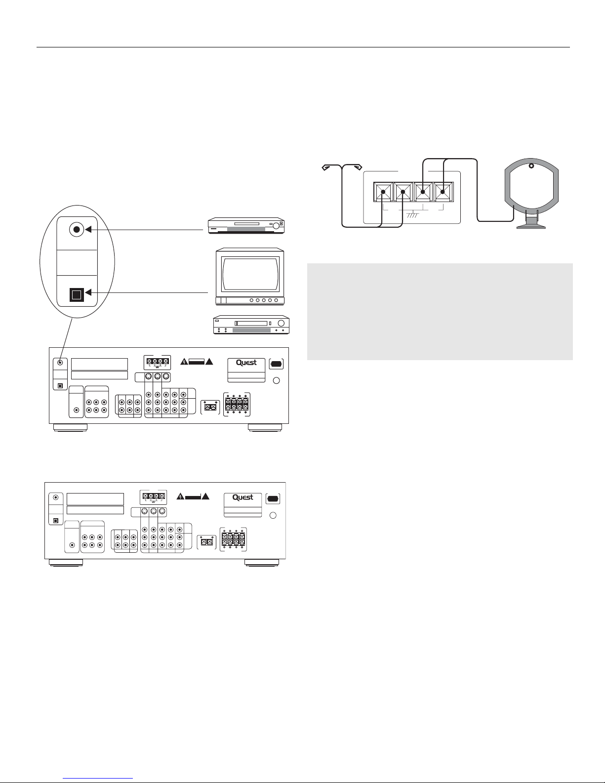
DIGITAL CONNECTION
Read instructions carefully when connecting
components to the receiver.
Digital In Jacks can accept Dolby Digital (AC-3), or
PCM signals when compatible components are
connected
CONNECTING THE ANTENNAS
The AM and FM antennas connect to the AM and
FM terminals on the system’s back panel.
They must be hooked up in order to receive clear
reception.
AM Loop antenna & FM indoor antenna
1. Uncoil the antenna wire and locate the base end.
2. Press down on the antenna tab to open
the terminal.
HINT
• For FM reception, extend antenna to its full length
and arrange the Antenna in a T shape.
• For AM reception, rotate antenna horizontally to
get better reception.
COAXIAL DIGITAL IN (AUDIO)
Connect to coaxial digital output of DVD,
CD, SAT or other compatible devices
COAXIAL
DIGITAL
IN
OPTICAL
This device complies with part 15 of the FCC rules. Operation is
subject to the following two conditions: (1) This device may not
cause harmful interference, and (2) This device must accept any
interference received, including interference that may cause
COAXIAL
undesired operation.
Manufactured under license from Dolby Laboratories.
DIGITAL
"Dolby", "Pro Logic" and double-D symbol are trademarks of
IN
Dolby Laboratories
OPTICAL
SUBWOOFER
OUT
FL SL CENTER
FR FL SUB
6CH. DIRECT INPUT
SAT / DVD / CD PLAYER
OPTICAL DIGITAL IN (AUDIO)
Optical fibre cable.
Connect to optical digital output of DVD,
CD, SAT or other compatible devices.
SAT / DVD / CD PLAYER / TV
IN OUT IN
L
R
TAPE
ANTENNA
FM
75Ω
LOOP
S-VIDEO
CD DVD SAT VCR 1
RISK OF ELECTRIC SHOCK
AVIS: RISQUE DE CHOC
AM
ÉLECTRIQUE - NE PAS OUVRIR
WARNING: TO REDUCE THE RISK OF FIRE OR ELECTRIC SHOCK,
DO NOT EXPOSE THIS APPLIANCE TO RAIN OR MOISTURE.
AVERTISSEMENT: AFIN D'ÉVITER LES DANGERS D'INCENDIE ET
D'ÉLECTROCUTION, NE PAS EXPOSER CET APPAREIL À LA PLUIE
NI À L'HUMIDITE.
MON.OUT
IN OUT MON.OUT
VIDEO
L
AUDIO
R
TV
CAUTION
DO NOT OPEN
!
CENTER SPEAKER(8Ω)
AUDIO VIDEO RECEIVER
MODEL NO.: QSR5000
POWER SOURCE: 120V/60Hz
POWER CONSUMPTION: 320W
MADE IN CHINA
MAIN SPEAKERS(8Ω)
RL
RL
REAR SPEAKERS(8Ω)
120V 60Hz
AC
˜
U
L
CUS
®
LISTED
ANTENNA
FM
75
AM
LOOP
This device complies with part 15 of the FCC rules. Operation is
subject to the following two conditions: (1) This device may not
cause harmful interference, and (2) This device must accept any
interference received, including interference that may cause
COAXIAL
undesired operation.
Manufactured under license from Dolby Laboratories.
DIGITAL
"Dolby", "Pro Logic" and double-D symbol are trademarks of
IN
Dolby Laboratories
OPTICAL
SUBWOOFER
OUT
FL SL CENTER
FR FL SUB
6CH. DIRECT INPUT
IN OUT IN
L
R
TAPE
ANTENNA
AM
FM
LOOP
75Ω
S-VIDEO
MON.OUT
CD DVD SAT VCR 1
CAUTION
RISK OF ELECTRIC SHOCK
DO NOT OPEN
AVIS: RISQUE DE CHOC
ÉLECTRIQUE - NE PAS OUVRIR
WARNING: TO REDUCE THE RISK OF FIRE OR ELECTRIC SHOCK,
DO NOT EXPOSE THIS APPLIANCE TO RAIN OR MOISTURE.
AVERTISSEMENT: AFIN D'ÉVITER LES DANGERS D'INCENDIE ET
D'ÉLECTROCUTION, NE PAS EXPOSER CET APPAREIL À LA PLUIE
NI À L'HUMIDITE.
IN OUT MON.OUT
VIDEO
L
AUDIO
R
TV
!
CENTER SPEAKER(8Ω)
AUDIO VIDEO RECEIVER
MODEL NO.: QSR5000
POWER SOURCE: 120V/60Hz
POWER CONSUMPTION: 320W
MADE IN CHINA
MAIN SPEAKERS(8Ω)
RL
RL
REAR SPEAKERS(8Ω)
AC
120V 60Hz
˜
U
L
CUS
®
LISTED
Page 8
GETTING STARTED
6
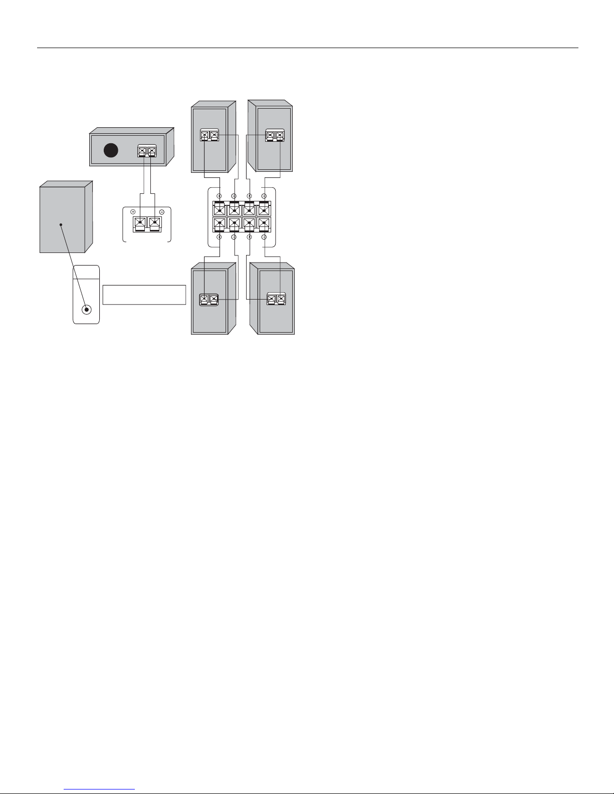
CONNECTING THE SPEAKERS
Speakers
You will need to use 6 speakers with the unit (2
front, 1 center, 2 rear, 1 subwoofer). In order to
enjoy good surround effects all six speakers need to
be connected to the receiver.
At least two front speakers (left and right) are
required. For better sound quality, center speaker,
rear speakers and subwoofer should also be
connected. Adding center and rear speakers will
enhance surround effects. Adding a Subwoofer will
increase bass response.
If you want to enjoy full range of sound effects, with
small speakers, it is a must to use the subwoofer
with the speakers to maintain adequate bass signal.
Speaker cords
1 for each speaker is needed for connection. Twist
the stripped ends of the speaker cord about
2/3”(15mm). Press down on the tab to open the
terminal and insert the wire. Snap the tab closed.
To ease speaker connections, the terminals are color
coded.
• Red/Black (Front Speakers)
• Blue”Black (Center Speaker)
• Grey/Black (Rear Speakers)
Connect the L, R speaker to the red/black terminal
on the receiver. Do the same for the center (with
blue/black terminal), rear speaker (with grey/black
terminal).
Speaker polarity
When connecting the speakers, make sure the
polarities (“+” speaker wire to “+” on the receiver)
of speaker wires and terminals are matched. If the
cords are reversed, the sound will be distorted and
will lack bass ("out of phase" effect).
CONNECTING THE SUBWOOFER
To connect your own powered subwoofer, a mono
aural audio cord (not supplied) is needed
(RCA terminal).
This receiver offers a high flexibility for user to use
a large variety of speakers and subwoofers. For
more information please refer to section "Fine
Setting of the Speakers" in “Advanced Sound
Control" on page 18.
RIGHT LEFT
MAIN SPEAKERS(8)
RL
RL
REAR SPEAKERS(8)
RIGHT
LEFT
SUBWOOFER
OUT
CENTER SPEAKER(8)
Use this jack on the left back panel
to connect another powered subwoofer
other than the one supplied.
Page 9
GETTING STARTED
7
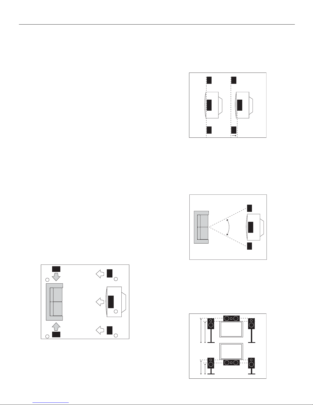
POSITIONING YOUR SPEAKERS
1) Left & Right (Front Speakers)
They carry primary music and sound effects.
2) Center Speaker
In surround mode, the center speaker carries much
of the dialogue as well as music and effects. It
should be set between the left and right speakers.
3) Surround (Rear Speakers)
Their overall sound balance should be as close as
possible to the front speakers. Proper placement is
vital to establish an evenly distributed sound field.
Subwoofer
A subwoofer is designed to reproduce powerful low
bass effects (explosions, the rumble of spaceships,
etc.) which dramatically heightens involvement
with the action on the screen. It is therefore
recommended to connect subwoofers when small
speakers are used.
Magnetic shielding
Speakers placed less than two feet from the TV set
must be magnetically shielded in order to prevent
picture distortion.
It is not recommended to place the rear speakers
near the TV set.
FRONT SPEAKER PLACEMENT
Even if you can’t duplicte this ideal home theater
setup exactly, the suggestions for speaker placement
that follow will help you get good results.
Alignment
Align the center speaker evenly with (A), or slightly
behind (B), the left and right speakers, but not
ahead of them.
ADVANCED SETTING
Angle
Placing the left and right speakers to form a 45
degree angle with your favorite viewing position
will duplicate the soundtrack mixer’s perspective.
Height
The mid and high frequency drivers of the three
front speakers should be as close as possible to the
same height. This often requires placing the center
speaker directly atop (A) or beneath (B) the TV set.
BA
3
3
1
2
1
45º
A
B
Page 10
GETTING STARTED
8
PREFERRED SOUND PLACEMENT
Location
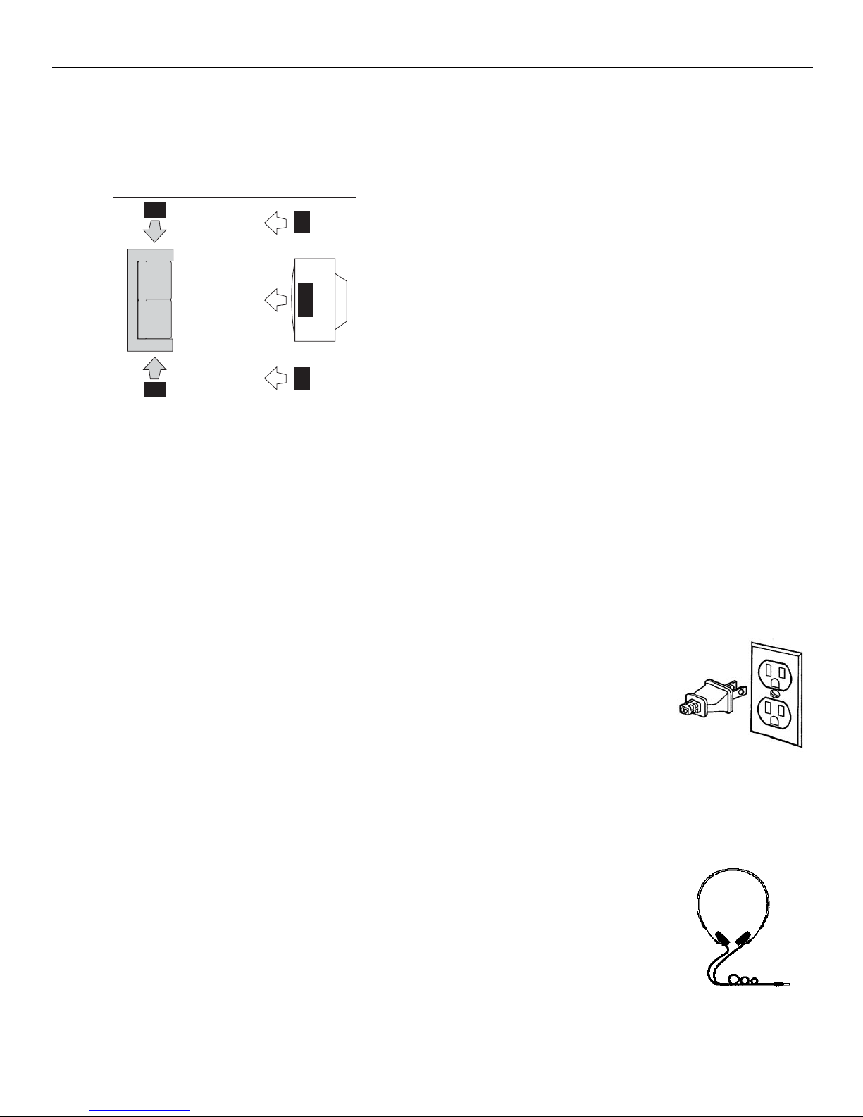
If possible, place surround speakers to either side of
the listening area, not behind it.
Height
If space permits, install surrounds 2-3 feet above
viewers. This helps to minimize localization effects.
Aiming
Aiming surrounds straight across the room, not
down at viewers, helps create a more open,
spacious surround soun field.
ADVANCED SURROUND SETTING
ALTERNATIVE SURROUND PLACEMENT
Rear wall
If rear wall mounting is the only choice, aim the
speakers at each other, towards the front or even
towards the sidewalls. Experiment with placement
until surround sounds seem to envelop you, rather
than coming from behind you.
No adjacent walls
Surrounds can go on stands facing each other to
approximate the preferred sidewall mounting, or to
the sides or rear of the viewing area aimed
upwards. In the latter case, they can go right on the
floor, or preferably, a few feet off the floor such as
on end tables.
TEST TONE/CHANNEL BALANCE
Channel balance
Your receiver is equipped with a test signal
generator for balancing the channels. As the signal
“travels” from channel to channel, adjust the level
controls until each channel plays at the same
loudness level. (For details see operation of
test/setup)
Level adjustment & surround channel
level expectations
Even though you adjust the surround channel to be
as loud as the others on the test signal, you’ll find
that on actual program material the surround
channel is usually much lower than the front. Don’t
be tempted to readjust the surround level; program
producers use surround mostly for subtle
atmosphereics and ambience, and only rarely for
special effects. A good surround mix doesn’t call
attention to itself; if it did, it would soon become
distracting.
Connecting for power
Make sure you connect all your
other electronic components
and the speakers before
plugging your receiver into the
outlet. Plug the power cord in
the wall outlet, matching the
wide blade of the plug with the
wide slot in the outlet. Be sure
to insert the plug completely.
Using headphones
To listen privately through your
audio system, use the PHONES
jack on the receiver. However,
make sure you turn down the
volume before you put on
the headphones. Increase the
volume to the desired level
after headphones are in place.
Page 11
OPERATING YOUR RECEIVER
9
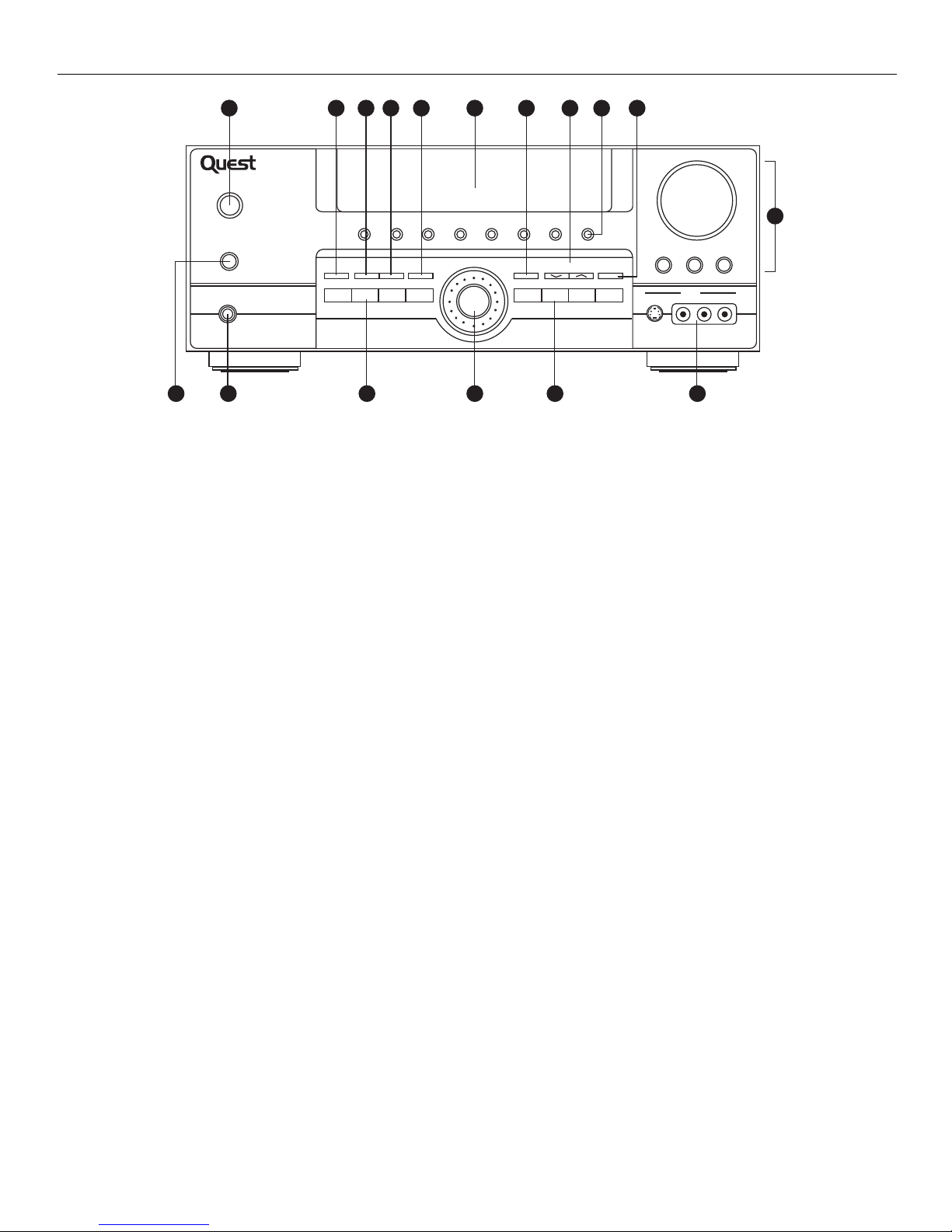
RECEIVER CONTROLS
1. Standby/On
To turn the unit on/off. When the system is turned on, the unit will go
to the mode it was in before power off.
2. Mute
To mute all audio outputs.
3.Phones
Plug your headphones (not supplied) into it for your private
enjoyment. Speakers will be off when phones are inserted.
4. Source Buttons
To select sound source. For e.g. CD, SAT, etc.
5. Display
To display current status of the receiver.
6. Sound Control
Lets you adjust the sound-volume, treble, bass & balance.
• To change the VOLUME, turn the large central knob.
• To adjust TREBLE or BASS, press relevant button and turn the knob.
• To change the volume of individual speaker, press LEVEL button
repeatedly to select the speaker, then turn the knob to adjust the level.
(Refer to “the TEST/SET UP button” on page 20)
7.DSP (Digital Sound Processor) & Night mode
Press corresponding button to select the DSP mode
(STADIUM/CONCERT/THEATER/EARENA/CHURCH/CLUB/OFF)
you want. (DSP will not function under DIGITAL input). Press NIGHT
for your enjoyment at night (see page 18). (Night mode can be used
only during dolby digital 5.1 mode).
8. Multi Jog, Mode/Set
When pressing MODE/SET repeatedly, the display will
toggle among Audio Source (for DVD, SAT & CD), SLEEP mode
and DIM selection.
Please refer on page 18 for “Input Signal Setting”.
• In SLEEP mode, you can set the receiver to turn off after 30, 60, 90
or 120 minutes.
• In DIM selection, you can rotate to set the brightness of the display.
Such settings will be stored.
• Use MULTI JOG for speakers and subwoofers setup and preset
radio stations selection.
9. Tuning
Press for about 2 seconds to activate AUTOMATIC PRESET function.
Press once to review all preset stations.
10. P. Scan (Preset Scan)
• Press and hold for about 2 seconds to start the automatic tuner
station preset.
• Press to view preset stations one by one.
11. Surr. Mode
Press to select the sound mode that you want. (Refer to “Advanced
Sound Control” on page 17).
12. 6 CH (6 Channels External Input)
Press to select the input connected to an external 6-Channel decoder.
13. Test/Set Up
When pressing it briefly, a short noise (test tone) will be generated in
the speakers one by one. When keeping pressed for 2 seconds, it will
enter SETUP mode for speakers and subwoofers. Rotate the MULTI
JOG knob to choose the options. (Refer to “the TEST/SET UP button
on page 20).
14. Preset EQ
Press repeatedly to select the desirable EQ mode (music style)
CLASSIC/POP/ROCK/JAZZ/VOCAL/or FLAT. Your choice will be
saved automatically. (EQ will not function under DIGITAL input).
15. Bypass
Press to go back to stereo sound (no DSP effect, no sound from
center and surround speakers).
16. VCR2/Video Cam Input
For convenient use of your digital camera, family game machines,
second VCR, etc.
DOLBY DIGITAL SURROUND RECEIVER
VCR 2 CD
POWER (STANDBY)
MUTE
PHONES
REMOTE
SENSOR
STADIUM CONCERT THEATER CHURCH ARENA CLUB DSP OFF NIGHT
SURR. MODE TEST/SET UPPRESET EQ BY PASS
DVD
SAT VCR 1
MODE/
SET
1213151411 953
6 CH. P. SCANTUNING
FM/AM TV TAPE
7 10
VOLUME
TREBLE
BASS
VCR 2
VIDEO
S-VIDEO L AUDIO R
1648432
6
LEVEL
Page 12
OPERATING YOUR RECEIVER
10
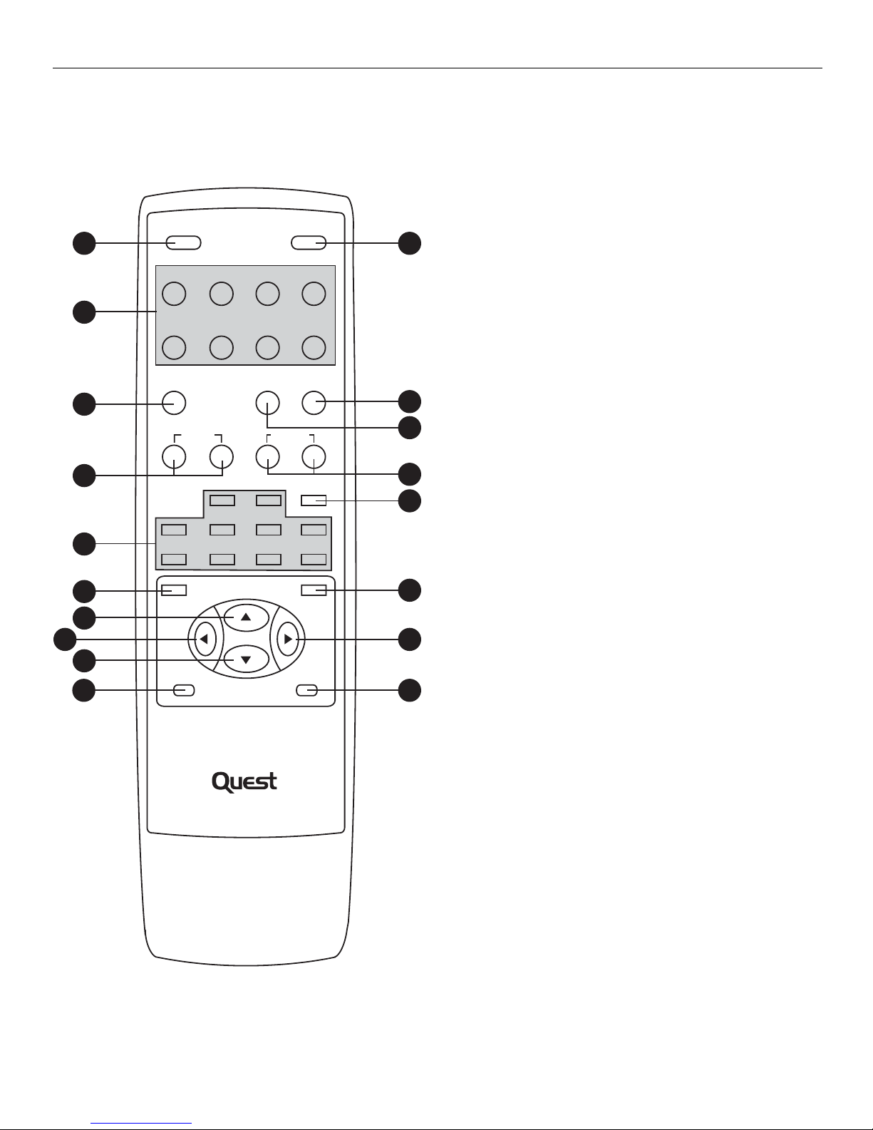
YOUR REMOTE CONTROL
1. On/Off
To turn on or off the receiver.
2. Source Buttons
To turn on and select various audio/video sources. You can also enter
the 6 channels direct input mode by pressing DVD/6CH.
3. Preset EQ
4. Tuning
5. Number Buttons
To access directly a pre-set station or to peripheral devices
(in TUNER mode).
6.Digital
Select the way your audio/video components are connected to the
receiver (Analog, Optical, Coaxial or Input/Output).
7. Left/Right Arrow
Buttons used to adjust the receiver in the LEVEL modes.
8. Vol (Volume Buttons)
To adjust the volume
9. Surr (Surround Sound Control)
Press to change the surround sound settings. The display will toggle
among DOLBY DIGITAL, DOLBY PROLOGIC, DOLBY 3 STEREO,
STEREO and DSP modes.
10. Level
Press to adjust the volume of the individual speaker. Press
repeatedly and the display will toggle among different channels (Left
front speaker, Right front speaker, Center speaker, Left rear speaker,
Right rear speaker and Subwoofer). Press the left and right arrow
buttons adjustment.
11. Test
When pressing, a short noise (test tone) will be generated in the
speakers one by one.
12. Memory
Used to manually store radio stations in the unit’s memory.
13. Channel Up/Down buttons
Used to select programmedstations (in TUNER mode).
14. Sleep
Press repeatedly to put the unit in the sleep mode. Unit will scroll
between 30, 60, 90 & 120 minutes with each press of the button.
15. Dimmer
Press repeatedly to change brightness of the display.
16. Mute
To mute all audio outputs
(For details, refer to section “Advanced Sound Control” on Page 17)
POWER
1
SAT DVD/6CH. VCR 1 VCR 2
MUTE
16
2
CD TAPE TV TUNER
PRESET EQ. SLEEP DIMMER
3
15
TUNING
CHANNEL
14
4
12
453
MEMORY
6
5
897
6
0
TESTDIGITAL
8
7
VOLUME
8
SURR. MODE
LEVEL
13
12
11
7
109
QSR5000
REMOTE CONTROL UNIT
Page 13
OPERATING YOUR RECEIVER
11
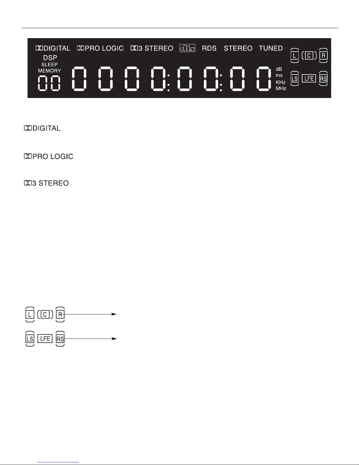
DISPLAY
• Audio output is in Dolby Digital mode.
• Audio output is in Dolby Pro Logic mode.
• Audio output is in 3 Stereo mode.
STEREO
• Tuner stereo signal detected.
TUNED
• Tuner station detected.
DSP
Sound Source/Speakers icons
• Tuner station detected.
SLEEP
• Unit is in Sleep mode.
KHz
MHz
• tuner frequency unit.
The letter indicates the input source
of this channel.
The square box indicates which
speaker is active.
Page 14
OPERATING YOUR RECEIVER
12
SWITCHING ON/OFF
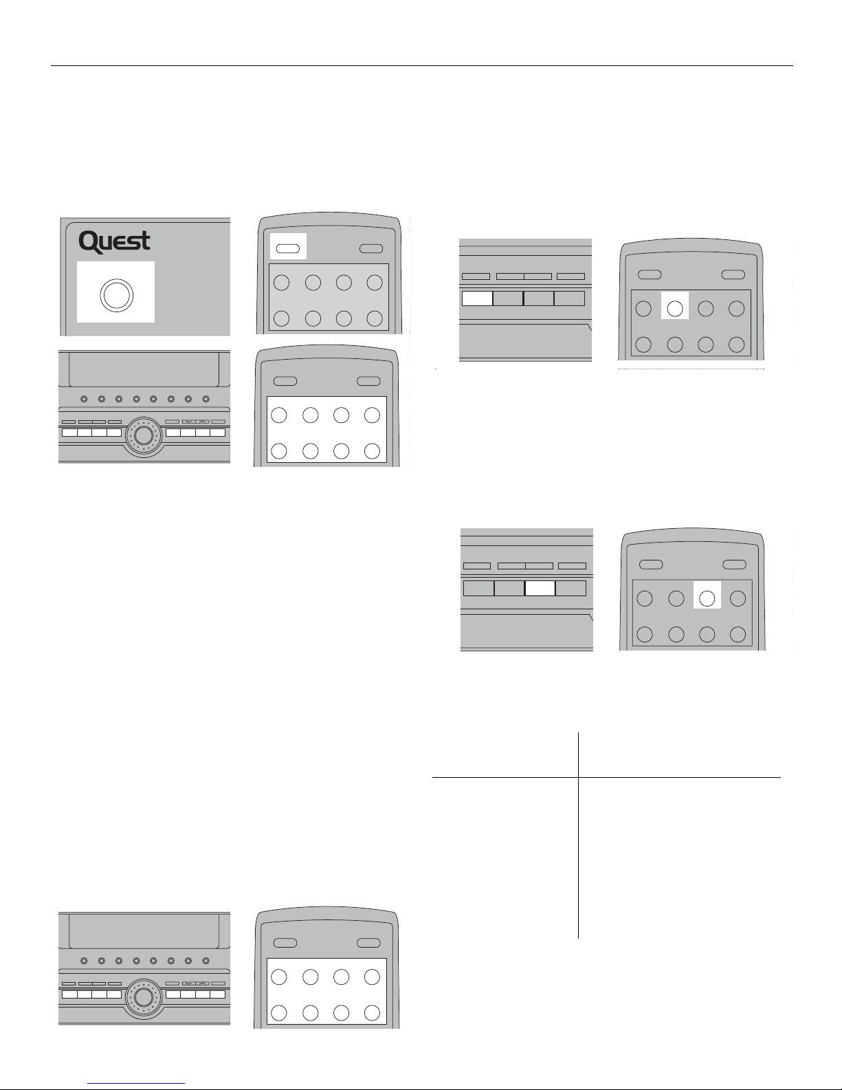
• To switch to the receiver, press STANDBY/ON
button once. Alternatively, you can press any of the
source buttons to power on the receiver.
• Standby: when the receiver is on, press the
STANDBY/ON button once to activate the standby
mode.
• To switch off the unit completely, unplug the power
cord from the socket.
NOTE:
Your receiver has a back up memory to keep your
settings like preset radio station for about 2 weeks
in case electricity cut occurs. If the receiver is
unplugged for more than 2 weeks, all the settings
will be lost and re-setting will be necessary.
SELECTION OF AUDIO/VIDEO SOURCE
When one of the source buttons is pressed, the
audio and video input corresponding to the name
will be activated.
The receiver acts as a switching device between all
the sources that are plugged into to it.
STADIUM CONCERT THEATER CH
MUTE
PHONES
DVD
SURR. MODE TEST/SET UPPRESET EQBY PASS
SAT VCR 1 VCR 2
DOLBY DIGIT
REMOTE
SENSOR
POWER (STANDBY)
STADIUM CONCERT THEATER CHURCH ARENA CLUB DSP OFF NIGHT
BASS
TREBLE
VIDEO
VCR 2
S-VIDEO L AUDIO R
LEVEL
DVD
SURR. MODE TEST/SET UPPRESET EQ BY PASS
SAT VCR 1 VCR 2 CD
6 CH. P. SCANTUNING
VOLUME
FM/AM TV TAPE
DOLBY DIGITAL SURROUND RECEIVER
REMOTE
SENSOR
MODE/
SET
PRESET EQ. SLEEP DIMMER
MEMORY
MUTE
TUNING
CHANNEL
6
0
12
453
897
SAT DVD/6CH. VCR 1 VCR 2
CD TAPE TV TUNER
POWER
MUTE
POWER
SAT DVD/6CH. VCR 1 VCR 2
CD TAPE TV TUNER
Example 1:
If you connect a DVD player to the DVD input
(audio & video) on the receiver and press the DVD
button, you will be able to have the sound and
image transmitted by the DVD.
Example 2:
Based on example 1, the DVD is playing, if a
VCR is connected to the VCR 1 input (audio &
video) of the receiver and the VCR1 button is
pressed, image and sound from the VCR source will
replace the DVD.
You can connect up to 7 audio/Video sources to
this amplifier.
STADIUM CONCERT THEATER CHURCH ARENA CLUB DSP OFF NIGHT
BASS
TREBLE
VIDEO
VCR 2
S-VIDEO L AUDIO R
LEVEL
DVD
SURR. MODE TEST/SET UPPRESET EQBY PASS
SAT VCR 1 VCR 2 CD
6 CH. P. SCANTUNING
VOLUME
FM/AM TV TAPE
DOLBY DIGITAL SURROUND RECEIVER
REMOTE
SENSOR
MODE/
SET
PRESET EQ. SLEEP DIMMER
MUTE
POWER
SAT DVD/6CH. VCR 1 VCR 2
CD TAPE TV TUNER
SURR. MODE TEST/SET UPPRESET EQ BY PASS
CD
6 CH. P. SCANTUNING
FM/AM TV TAPESAT VCR 1 VCR 2DVD
MUTE
POWER
SAT VCR 1 VCR 2
CD TAPE TV TUNER
DVD/6CH.
SURR. MODE TEST/SET UPPRESET EQ BY PASS
CD
6 CH. P. SCANTUNING
FM/AM TV TAPESAT VCR 2DVD VCR 1
PRESET EQ. SLEEP DIMMER
MUTE
POWER
SAT VCR 2
CD TAPE TV TUNER
DVD/6CH. VCR 1
Source Button
(Receiver front panel)
DVD
SAT
VCR-1
VCR-2
CD
TV
TAPE
FM/AM
Corresponding Connector
(Receiver back panel)
DVD IN (audio/Video)
SAT IN (audio/Video)
VCR-1 IN (audio/Video)
VCR-2 IN (audio/Video)
CD IN (audio/Video)
TV IN (audio/Video)
TAPE IN (audio/Video)
Built-in
Page 15
OPERATING YOUR RECEIVER
13
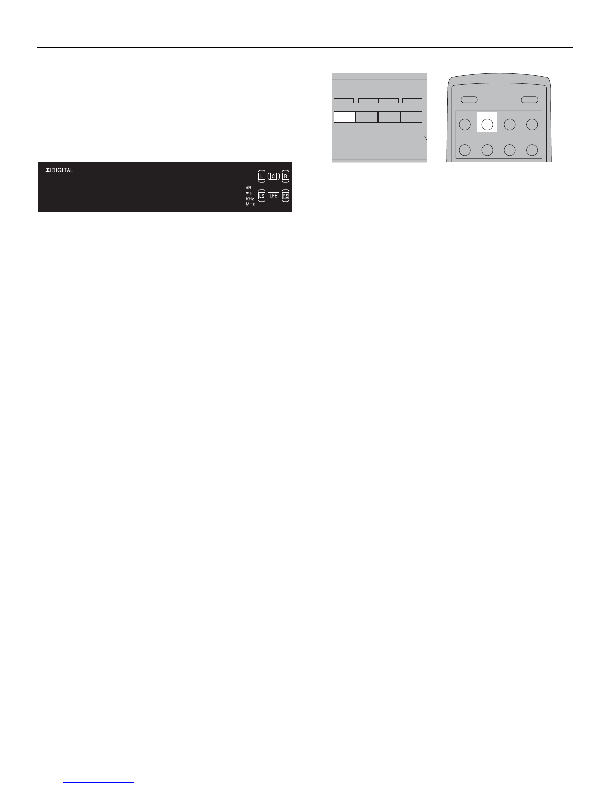
When a source is selected, the source name will be
shown on the display.
Example:
Press DVD to select DVD as the source to the
amplifier.
NOTE:
1) Your receiver has a built in tuner. Just connect the
appropriate antenna on the back of the receiver
and you will be able to listen to radio stations. (See
details in Tuner section).
2) Other sources can be connected to the above
standard source.
Example:
You can connect an LD into the DVD inputs.
3) Refer to the “Connecting to Audio-Visual
Components” section for details on connection.
USING THE RECEIVER TO PLAY A SOURCE
After having properly connected a source (DVD,
CD, VCR) to the receiver, you can partly control
them through the receiver.
Playing a DVD with the receiver
1) Connect a DVD player to the receiver (see
connecting your receiver for details).
NOTE:
To play Dolby Digital sound, the source must be
Dolby Digital encoded and connected to the
receiver via the optical or coaxial terminal (see
“Digital Connection” on page 5 for details).
2) Press STANDBY/ON to switch on the receiver.
3) Select the DVD source by pressing the DVD
source button.
4) Switch on the DVD player and start playback.
5) Switch on your TV.
6) Select the appropriate A/V channel on the TV
(refer to your TV manual for details) until the image
from the DVD player is displayed.
7) Set the sound mode if needed (see “Advanced
sound control” on page 17 for details).
ATTENTION: If you connect the DVD and Receiver with ANALOG
signal (RCA cord). Please make sure to turn on ANALOG output in
your DVD player.
Example 1:
To play 5.1 Dolby Digital surround sound press the
Surr. mode button until “Dolby Digital” appears on
the display and all of the speakers icons light up.
Example 2:
DVD: You may also need to select the Dolby Digital
5.1 on the DVD disc menu to have the digital
surround enabled providing that the disc is
encoded with Dolby Digital 5.1 (please refer to the
DVD player and DVD disc instruction.)
ATTENTION: To play Dolby Digital, you must connect the DVD and
the receiver with DIGITAL signal (Coaxial or Optical). Not ANALOG
(RCA cord).
Example 3:
LD: You may need to select a different Audio
Channel on your LD (refer to your LD player
manual.)
8) Adjust volume knob accordingly.
SURR. MODE TEST/SET UPPRESET EQ BY PASS
CD
6 CH. P. SCANTUNING
FM/AM TV TAPESAT VCR 1 VCR 2DVD
MUTE
POWER
SAT VCR 1 VCR 2
CD TAPE TV TUNER
DVD/6CH.
D V D
Page 16
OPERATING YOUR RECEIVER
14
OPERATING THE RADIO
The receiver has a built-in tuner that allows for
AM/FM radio function.
Manual Tuning
1) Connect the FM and AM antenna accordingly
(See “Connecting the Antennas” section on page 5
for details).
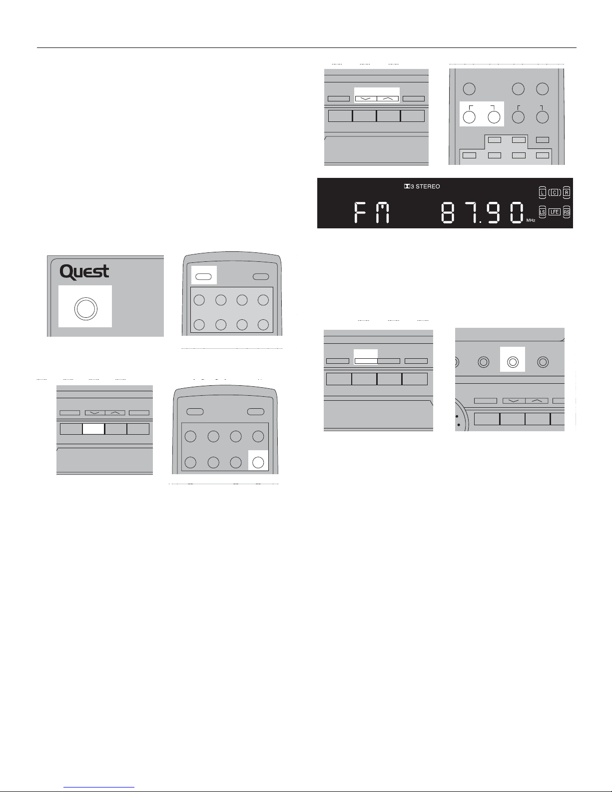
2) Press STANDBY/ON to switch on the receiver.
3) Press FM/AM or press TUNER on the remote.
4) To select band, press the FM/AM button or press
TUNER on the remote again to toggle between
FM/AM mode.
When an FM station broadcast stereo sound,
STEREO is displayed.
5) Tune the stations by pressing TUNING UP
or TUNING DOWN repeatedly until the desired
station is found. Alternatively, you can press
and hold TUNING UP or TUNING DOWN
for about one second to activate the automatic
SEARCH function. In this mode the receiver
will automatically tune frequencies until it finds a
station.
STADIUM CONCERT THEATER CHURC
MUTE
DOLBY DIGITAL S
REMOTE
SENSOR
POWER (STANDBY)
PRESET EQ. SLEEP DIMMER
MUTE
SAT DVD/6CH. VCR 1 VCR 2
CD TAPE TV TUNER
POWER
BASS TREBLE
VIDEO
VCR 2
S-VIDEO L AUDIO R
LEVEL
6 CH. P. SCANTUNING
CD FM/AM TV TAPE
PRESET EQ. SLEEP DIMMER
MUTE
POWER
SAT VCR 1 VCR 2
CD TAPE TV
DVD/6CH.
TUNER
BASS TREBLE
VIDEO
VCR 2
S-VIDEO L AUDIO R
LEVEL
6 CH. P. SCAN
CD FM/AM TV TAPE
TUNING
PRESET EQ. SLEEP DIMMER
MEMORY
CHANNEL
6
12
453
TUNING
6) Repeat steps 4 & 5 to tune another radio station.
Select sound effects if needed by pressing PRESET
EQ or DSP sound (See ”Advanced Sound” section
for details).
NOTE:
1) If there is interference, modify the location of the
antenna until the optional sound is heard. TV and
other electronic devices could be the cause of the
interference, so try to position the antenna away
from them.
2 ) A weak signal can affect the “Auto Search”
function. Adjust the antenna for better reception for
more efficient search.
SURR. MODE TEST/SET UP
SAT VCR 1 VCR 2DVD
PRESET EQ BY PASS
STADIUM CONCERT THEATER CHURCH
RR. MODE TEST/SET UPPRESET EQBY PASS
SAT VCR 1 VCR 2DVD
ARENA CLUB NIGHT
CD
6 CH. P. SCANTUNING
FM/AM TV TAPE
DSP OFF
Page 17
OPERATING YOUR RECEIVER
15
Storing Radio Stations:
The receiver can store up to 30 radio stations in
memory. You can enter every single radio station
yourself or the receiver can store all available radio
station automatically in an ascending order.
Automatic Preset Storing
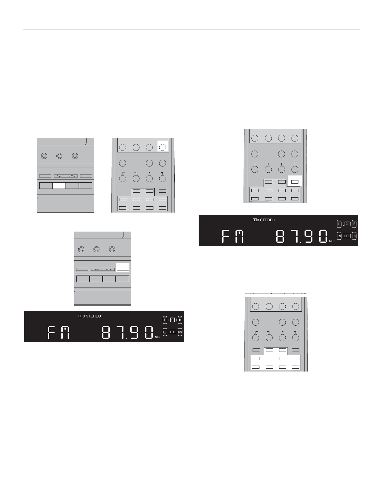
1) Select the band wave by pressing Tuner
repeatedly.
2) Press and hold P.SCAN for 3 seconds.
Radio frequencies will be browsed and radio station stored automatically. When all available radio
stations are stored or if all 30 memory locations are
full, the auto preset will stop.
NOTE:
Weak signal can affect the “Automatic Preset
Storing function” efficiency. Adjust the antenna for
the best reception for more efficient search.
STADIUM CONCERT THEATER CHURCH ARENA CLUB DSP OFF NIGHT
BAS
S-VIDEO
CD
6 CH. P. SCANTUNING
FM/AM TV TAPESAT VCR 1 VCR 2DVD
ARENA CLUB NIGHT
BASS
TREBLE
VIDEO
VCR 2
S-VIDEO L AUDIO R
LEVEL
CD
6 CH. P. SCANTUNING
TV TAPE
DSP OFF
FM/AM
PRESET EQ. SLEEP DIMMER
MEMORY
TUNING CHANNEL
6
0
12
453
897
CD TAPE TV TUNER
STADIUM CONCERT THEATER CHURCH ARENA CLUB DSP OFF NIG
SURR. MODE TEST/SET UPPRESET EQBY PASS
CD
6 CH. TUNING
FM/AM TVSAT VCR 1 VCR 2DVD
BASS
TREBLE
VIDEO
VCR 2
S-VIDEO L AUDIO R
LEVEL
TEST/SET UP
CD
6 CH. TUNING
TV TAPEVCR 2
DSP OFF
FM/AM
P. SCAN
Manual Preset
1) Select the band wave by pressing TUNER
repeatedly.
2) Tune to a radio station (see “Manual Tuning” on
page 14 for details).
3) Press MEMORY on the remote control. “MEM”
will appear on the display.
4) While the word “MEM” is still on, input your
desired preset number (1-30) using the numeric
keys on the remote control to store the radio station.
PRESET EQ. SLEEP DIMMER
TUNING
CHANNEL
6
0
12
453
897
CD TAPE TV TUNER
MEMORY
CD TAPE TV TUNER
PRESET EQ. SLEEP DIMMER
TUNING
FM MODE MEMORY
CHANNEL
12
453
897
6
0
Page 18
OPERATING YOUR RECEIVER
16
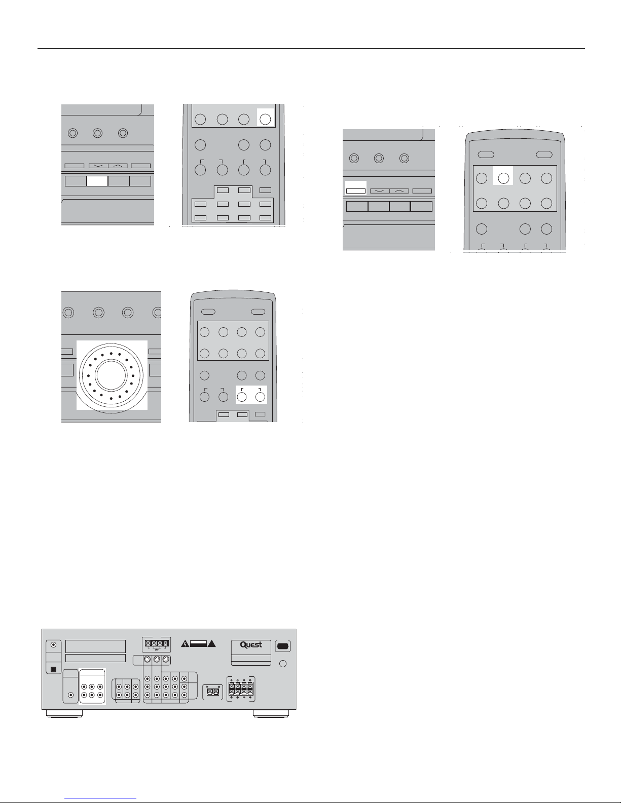
Retrieving Preset Stations
1) Press FM/AM to select tuner mode.
2)Rotate MULTI JOG on the receiver or press
CH+ or CH- buttons on the remote to select
preset stations.
Radio frequencies will be browsed and radio sta-
tion stored automatically. When all available radio
Channel External Input
An external decoder (DTS, Dolby Digital, etc...) or
a device with built-in multi-channel decoder and 6
channel output connector (DVD player, TV...) can be
connected to the 6CH input. It is therefore possible
to play any future 6 channel codings (SACD, DVD
audio) thanks to this connection. The external
decoder device will send the seperated audio
information to the receiver that will then amplify the
signal and send it to the appropriate speakers.
STADIUM CONCERT THEATER CHURCH ARENA CLUB DSP OFF NIGHT
BAS
S-VIDEO
CD
6 CH. P. SCANTUNING
FM/AM TV TAPESAT VCR 1 VCR 2DVD
ARENA CLUB NIGHT
BASS
TREBLE
VIDEO
VCR 2
S-VIDEO L AUDIO R
LEVEL
CD
6 CH. P. SCANTUNING
TV TAPE
DSP OFF
FM/AM
PRESET EQ. SLEEP DIMMER
MEMORY
TUNING CHANNEL
6
0
12
453
897
CD TAPE TV TUNER
CERT THEATER CHURCH ARENA CLUB DSP OFF NIGHT
BASS
VS-VIDEO
TEST/SET UPSS
CD
6 CH. P. SCANTUNING
FM/AM TV TAPE1 VCR 2
MODE
/SET
PRESET EQ. SLEEP DIMMER
MEMORY
MUTE
TUNING
6
12
453
SAT DVD/6CH. VCR 1 VCR 2
CD TAPE TV
POWER
TUNER
CHANNEL
To activate the 6 channel external input, press 6
CH on the receiver or press the DVD/6 CH button
on the remote control twice.
ATTENTION: With 6 Channel input, all DSP, EQ, and surround sound
modes (Stereo, 3-Stereo, Dolby Prologic or 5.1 Channel) cannot
be activated.
STADIUM CONCERT THEATER CHURCH ARENA CLUB DSP OFF NIGHT
BA
S-VIDEO
CD
6 CH. P. SCANTUNING
FM/AM TV TAPESAT VCR 1 VCR 2DVD
ARENA CLUB NIGHT
BASS
TREBLE
VIDEO
VCR 2
S-VIDEO L AUDIO R
LEVEL
CD
P. SCANTUNING
TV TAPE
DSP OFF
FM/AM
6 CH.
PRESET EQ. SLEEP DIMMER
MUTE
TUNING
CHANNEL
SAT VCR 1 VCR 2
CD TAPE TV
POWER
TUNER
DVD/6CH.
This device complies with part 15 of the FCC rules. Operation is
subject to the following two conditions: (1) This device may not
cause harmful interference, and (2) This device must accept any
interference received, including interference that may cause
COAXIAL
undesired operation.
Manufactured under license from Dolby Laboratories.
DIGITAL
"Dolby", "Pro Logic" and double-D symbol are trademarks of
IN
Dolby Laboratories
OPTICAL
SUBWOOFER
OUT
6CH. DIRECT INPUT
FL SL CENTER
FR FL SUB
IN OUT IN
L
R
TAPE
ANTENNA
FM
AM
75Ω
LOOP
WARNING: TO REDUCE THE RISK OF FIRE OR ELECTRIC SHOCK,
DO NOT EXPOSE THIS APPLIANCE TO RAIN OR MOISTURE.
AVERTISSEMENT: AFIN D'ÉVITER LES DANGERS D'INCENDIE ET
S-VIDEO
CD DVD SAT VCR 1
D'ÉLECTROCUTION, NE PAS EXPOSER CET APPAREIL À LA PLUIE
NI À L'HUMIDITE.
MON.OUT
IN OUT MON.OUT
TV
CAUTION
RISK OF ELECTRIC SHOCK
DO NOT OPEN
AVIS: RISQUE DE CHOC
ÉLECTRIQUE - NE PAS OUVRIR
VIDEO
L
AUDIO
R
!
CENTER SPEAKER(8Ω)
AUDIO VIDEO RECEIVER
MODEL NO.: QSR5000
POWER SOURCE: 120V/60Hz
POWER CONSUMPTION: 320W
MADE IN CHINA
MAIN SPEAKERS(8Ω)
RL
RL
REAR SPEAKERS(8Ω)
AC
120V 60Hz
˜
U
L
CUS
®
LISTED
Page 19
ADVANCED SOUND CONTROL
17
SOUND ENHANCEMENT SYSTEMS
This receiver is equipped with several built-in sound
enhancement systems.
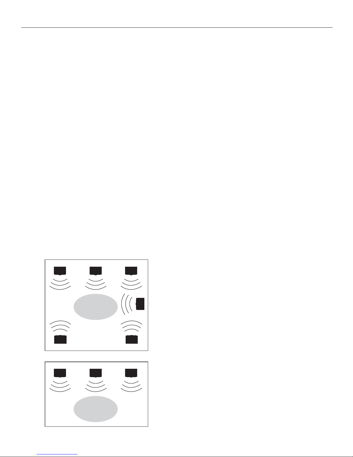
Dolby Pro Logic and Dolby 3 Stereo
This surround system reproduces theater-like
surround sound from Dolby-encoded software. The
Pro Logic mode uses the built-in circuit to steer the
Left, Center, Right and Surround channel audio
signals and uses all 5 speakers and an optional
subwoofer to play decoded Dolby Pro Logic
program sources such as a TV and VCR.
ATTENTION: To play Dolby Pro Logic, you must have 5 speakers
connected.
The 3-Stereo mode will redirect the surround
signals to the front left and right speakers when only
the front and center speakers are used
.
ATTENTION: To play 3-Stereo, you must have 3 speakers connected.
Use this mode to suit your speaker system
configurations (such as size and number of
speakers) and type of program (such as VCR).
Dolby Digital
The Dolby Digital mode lets you enjoy full digital
surround from software processed in the Dolby
Digital format. Dolby Digital provides better sound
quality and more powerful presence than
conventional Dolby Surround.
This unit is equipped with Dolby Digital 5.1-channel
so that you can enjoy enhanced full digital surround
sound. Being different from Dolby Pro Logic in
which only four channels ( Front Left, Front Right,
Centre and Rear) are used, the new system
provides stereo separation of the rear speakers
(Rear-Right, Rear-Left). These 5 channels, together
with the subwoofer channel for bass sounds
(counted as .1 channel), constitute as 5.1-Channel (
or 6 Channels ) input for Dolby Digital that brings
you the most sophisticated sound enjoyment.
ATTENTION: To play Dolby Digital 5.1, you must connect the DVD to
your receiver with digital signal (Coaxial or Optical) + the sound
source (DVD software) must be 5.1 encoded.
Recording Dolby Digital Source
To record from a digital (Optical or Coaxial) input
using a VCR/Tape that is connected to the receiver,
the sound must be set to stereo first. Press SURR.
MODE to select stereo mode.
If the receiver is set to 5.1 sound information
recording from surround speakers, the center
speaker will not be recorded.
DOLBY PRO LOGIC
FRONT LEFT SPEAKER
REAR LEFT SPEAKER
DOLBY 3-STEREO
FRONT LEFT SPEAKER
CENTER SPEAKER FRONT RIGHT SPEAKER
SUBWOOFER
LISTENING ZONE
REAR RIGHT SPEAKER
CENTER SPEAKER FRONT RIGHT SPEAKER
LISTENING ZONE
Page 20
ADVANCED SOUND CONTROL
18
Stereo
The stereo mode uses the two main channel outputs
from the front of the speakers. Use this mode if you
have connected the front speakers only.
DSP (Digital Sound Processor)
These digital sound effects resemble sounds in a
real environment such as Stadium, Concert, Theater,
Arena, Church, Club. DSP automatically converts
analog audio signals to digital ones which enables
you to adjust the sound without degrading the
sound quality. Different modes will give you
different feel of size and type of listening
environment. (Not available in Dolby Digital (DVD)
or during Digital input).
Night Mode
By using Dynamic Range Compression technology,
you can enjoy enhanced sound quality by Dolby
Digital at night without interrupting your roommates
or neighbors. While enjoying a Dolby Digital
enabled component (DVD, SAT), you can activate
NIGHT MODE by pressing the NIGHT button on the
front of the receiver and this mode will compress the
difference in volume between normal voices and
sounds like explosions.
ATTENTION: Night Mode can be functioned only during Dolby
Digital 5.1 playback.
FINE SETTING OF THE COMPONENTS
The receiver has pre-selected the best surround
mode for you once you turn on the unit by pressing
the SOURCE Buttons (like DVD, SAT, CD) directly.
If you decide to change the surround mode, you can
press the SURR. MODE button repeatedly to toggle
among the different surround mode choices and
select the one you want.
ATTENTION: To play Doby Digital 5.1, you must connect the DVD to
your receiver with a digital signal (Coaxial or Optical) + the sound
source (DVD software) must be 5.1 encoded.
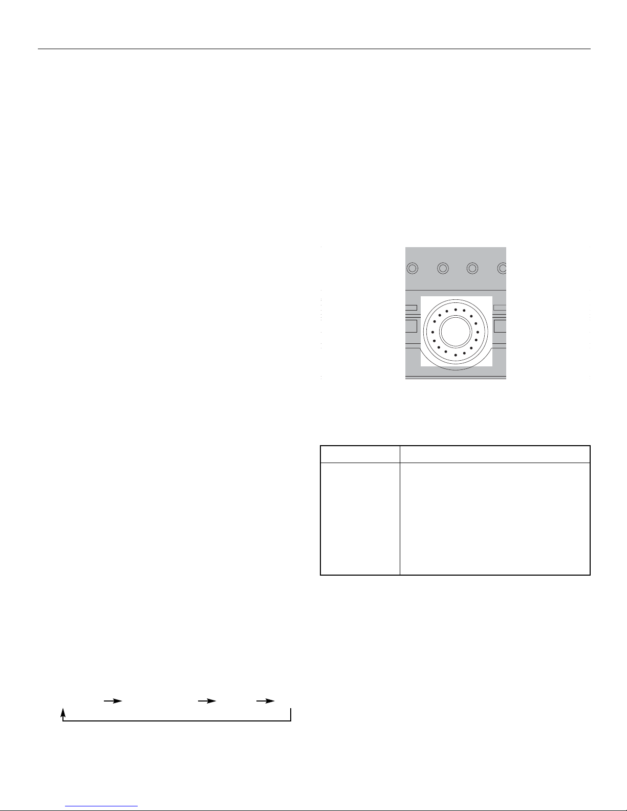
Dolby Pro Logic Dolby Digital 5.1 3-Stereo Stereo
Input Signal Setting
The receiver defaults to the most convenient settings
for your easiest use (see table).
If your connection is different from the default
setting:
1) Select the source
2) Press MODE/SET
3) Rotate MULTI JOG to toggle among
Optical/Coaxial/Analog to match your connection.
Your selection will be stored automatically.
Every time you press the source button, the input
setting (e.g. DVD/OPTI) will be shown on the
display for a few seconds.
Digital Input
Select this setting to play digital signals from a DVD,
CD, LD player, SAT or TV.
NOTE:
Digital input is only available for DVD, SAT, C D
and TV.
STADIUM CONCERT THEATER CHURCH ARENA CLUB DSP OFF NIGHT
CD
6 CH. P. SCANTUNING
FM/AM TV TAPESAT VCR 1 VCR 2DVD
MODE
/SET
Source Button
• SAT
• DVD
• CD
• VCR-1
• VCR-2
• FM/AM
• TAPE
• TV
Default Input (As seen on Display)
Analog (SAT/ANA)
Analog (DVD/ANA)
Analog (CD/ANL)
Analog (VCR1/ANL)
Analog (VCR2/ANL)
Built-in Tuner
Analog (TAPE/ANL)
Analog (TV/ANL)
Page 21
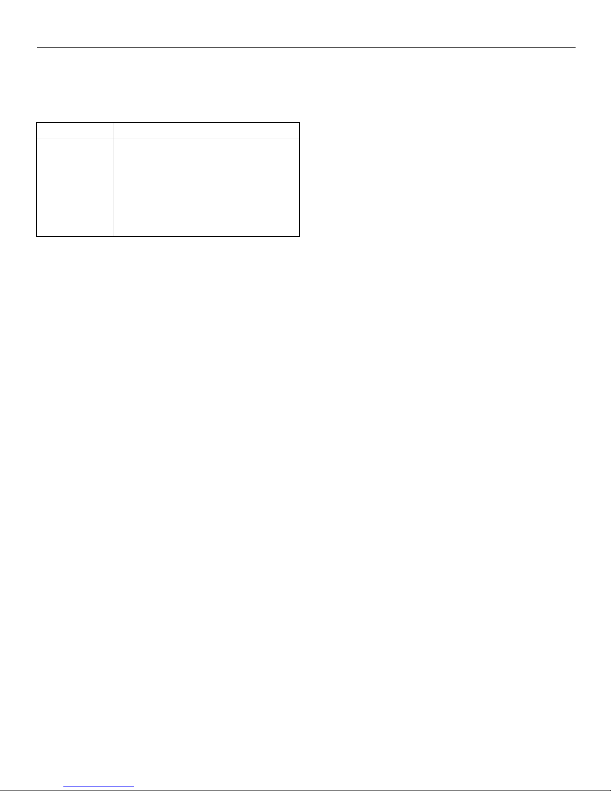
Input Signal Selection
Select this setting to play analog signals from a
cassette deck, VCR or turntable.
The Test/Set Up button
You can adjust the relative loudness of the speakers
by TEST/SET UP button. In Dolby modes, press the
button briefly. A short noise will be heard in the
speakers one by one. The speaker playing the noise
at that moment will be shown in the display.
Speaker Configurations
You can also change the setup of the speakers by
pressing the TEST/SET UP button until the display
shows “LARGE” or “SMALL” which enables you to
set the size of the speakers.
Press again, “SW” will be displayed and you can
set the subwoofer on or off.
Displaying Program Formats
When a digital source is playing, the receiver will
automatically switch to the proper surround mode
and indicates on the speaker icons on the right
hand side of the display.
It is important to note, however, that not all Dolby
Digital sources are encoded with full complement of
5 channels plus LFE*. Speaker icons show how
many and which speakers you have enabled and
the letters inside the speaker icons show which
channel is present in the source information.
*LFE stans for Low Frequency Effect. The indication “LFE”
appears if the digital source contains LFE information. In this
case, the bass signal will be delivered to the subwoofer,
offering more dynamic deep bass sound effects. If the letter is
flashing, the signal is either too weak or just gone.
ADVANCED SOUND CONTROL
19
Source Button
• SAT
• DVD
• CD
• VCR-1
• VCR-2
• TAPE
• TV
Available Input
ANL/Optical/Coaxial
ANL/Optical/Coaxial
ANL/Optical/Coaxial
ANL /-/ANL /-/ANL /-/ANL/Optical/-
Page 22

CARE AND MAINTENACE
20
RECEIVER/TUNER OPERATION
Stereo indicator is off.
• Adjust the antenna
The signal is Mono. Severe hum or noise
• The signal is too weak. Connect an external
antenna.
The Test/Set Up button
You can adjust the relative loudness of the speakers
by TEST/SET UP button. In Dolby modes, press the
button briefly. A short noise will be heard in the
speakers one by one. The speaker having the noise
at that moment will be shown in the display.
REMOTE CONTROL OPERATION
The remote control does not operate the unit.
• Another function mode is selected on the remote.
Press the correct Source button.
• No batteries installed.
Install the batteries before attempting to operate the
remote. Be sure to match the + and - ends of each
battery to the symbols shown in the remote battery
compartment.
•The batteries are weak.
Replace all batteries.
• The remote is pointed at the remote control sensor
on the main unit or there is an obstacle between the
remote and the main unit.
• The remote control is too far from the main unit,
move closer.
GENERAL
No Audio.
• Make sure the speakers are connected.
• Check the input connections.
• Check the power cord connections.
• Make sure the MUTE indicator on the front panel
is off.
• Make sure that the digital setting (Optical/
Coaxial/Analog) is correct.
No Audio from one channel.
• Check the speaker level setting.
• Check the speaker wire or cable connections.
Noise occurs when the TV is turned off.
• The TV is too close to the audio system.
Specific instruments sound displaced.
• Check the connections between the receiver and
the speakers if the sound does not match the video.
• Press the SOURCE button for the video source.
CLEANING THE EXTERIOR
Disconnect the system from AC power before
cleaning the exterior of the system with a soft dust
cloth, or with a slightly dampened leather chamois.
Never use strong solvents.
EQUIPMENT SPECIFICATIONS
Amplifier Section:
All 5 channels: 100W at 8 ohm. 0.9% THD @ 1kHz
Subwoofer Channel: Line out
Muting Attenuation: 65dB
Frequency Response: 40Hz - 6MHz @ +/- 3dB
Signal to Noise Ratio: 65dB (Bypass mode)
Video Section:
Input (Sensitivity/Impedance): 1Vp-p/75 ohm
Output (Level/Impedance): 1Vp-p/75 ohm
Frequency Response: 10Hz - 6MHz @ +/- 3dB
Signal to Noise Ratio: 40dB
Crosstalk @ 3.58MHz: 40dB
AM Tuner Section:
Frequency Response: 80Hz - 2KHz @ +/- 6dB
Usable Sensitivity: 800uV/m @ S/N 20dB
Signal to Noise: 38dB
Image Ratio: 27dB @ 1000KHz
IF Rejection: 35dB
FM Tuner Section:
Frequency Response: 40Hz - 15KHz @ +/- 3dB
Quieting: 24dBu
Signal to Noise: 60dB (stereo)/65dB (mono)
Image Ratio: 40dB
IF Rejection: 50dB
Page 23

LIMITED WARRANTY
21000 TransCanada • Baie D’Urfé • Qc • Canada • H9X 4B7
Tel.: (514) 457-2555 • Fax: (514) 457-0055
Toll Free Order Number: 1-800-567-3275 • Toll Free Fax Number : 1-866-457-5507
Quest warrants this product to be free from manufacturing defects in material and workmanship under
normal use for a period of 1 year from date of purchase, if service is required during the first year of
ownership, product should de returned to the store where it was purchased with the original receipt for an
exchange.
This warranty does not apply to any Quest product which is used for commercial, rental, or industrial
purpose, is damaged by accident, misuse, abuse, improper line voltage water lightning, or any acts of God.
This warranty is void if product is altered, modified, or if any parts of service covered by this warranty are
furnished by anyone other than Quest. This warranty does not cover cartons, carrying case, batteries,
cosmetic parts, broken or marred cabinets, magnetic tapes, compact discs, or any other accessories used
in connection with the product or consequential damages due to defect in the product.
This warranty is not transferable and only applies to the original purchase. Any implied warranties,
including the warranty of merchants, are limited in duration to the period of this expressed warranty and
no warranty whether express or implied shall apply to the product thereafter. Under no circumstance shall
Quest be liable for any loss or consequential damage arising out of the use of this product.
Page 24
IMPORTANT SAFETY INSTRUCTIONS
Before using the product, please follow and adhere to all warnings,
safety and operating instructions located on the product and in the user
book. Save all instructions for future reference.
Do not expose product to rain and do not use near water; such as, sink,
wet basement, swimming pools, etc.
Always leave sufficient space around the product for ventilaton. Do not
place product or on a bed, rug, in a bookcase or cabinet that may
prevent air flow through the vent openings.
Do not expose product to extreme temperatures such as found near a hot
radiator or stove, or in a car parked in the Summer sun.
Connect power cord only to AC power source as marked on the product.
Some products employ a polarized AC line plug (one blade is wider). This
is a safety feature. The plug will go in the power outlet only one way. If thge
plug doesn’t go into the outlet completely, turn the plug over and put it in
the other way. If it still doesn’t fit, contact a qualified electrician to change
the outlet. Do not defeat the safety purpose of the polarized plug.
Route power cord to prevent it from being pinched, or walked on, or
melted by a hot stove or radiator.
To clean cabinet, unplug AC power cord, then use a soft cloth dampened
only with water.
Do not place lit candles, cigarettes, cigars, etc. on the product.
Unplug AC power cord from outlet during a lightning strom or when
product is left unused for a long period of time to prevent damage due to
lightning or power line surges.
Care should be taken so that objects do not fall and liquids do not spill into
the product.
Never add accessories that the product has not been designed to
accommodate.
Use only the manufacturer’s approved mounting instructions and hardware
when installing product.
Do not attempt to disassemble the cabinet. This product does not contain
customer serviceable components.
Do not handle the unit or power cord when your hands are wet or damp.
•
•
•
•
•
•
•
•
•
•
•
•
•
•
•
Carts and Sands - The appliance should be used only with a cart that is
recommended by the manufacturer.
An appliance and cart combination should be moved with care. Quick
stops, excessive force, and uneven surfaces may cause the appliance and
cart combination to overturn.
Damage Requiring Service - This product should be serviced by qualified
service personnel when:
A) The power supply cord or plug has been damaged.
B) Objects have fallen, or liquid has been spilled into the product.
C) The product has been exposed to rain.
D) The product does not appear to operate normally or exhibits a marked
change in performance.
E) The product has been dropped, or the cabinet damaged.
When service or repairs are completed, ask the service technician to
perform the safety check described in the service manual and to confirm
that replacement parts have the same safety characteristics as the original
parts.
IF YOUR PRODUCT OPERATES ON BATTERIES, adhere to the following
precautions:
A) Any battery may leak electrolyte if mixed with a different battery type,
if inserted incorrectly, or if all batteries aren’t replaced at the same time.
B) Any battery may leak electrolyte or explode if disposed of in fire or an
attempt is made to charge a battery not intended to be recharged.
C) Discard leaky batteries immediately. Leaking batteries can cause skin
burns or other personal injury. When discarding batteries, be sure to
dispose of them in the proper manner, according to your state and local
regulations.
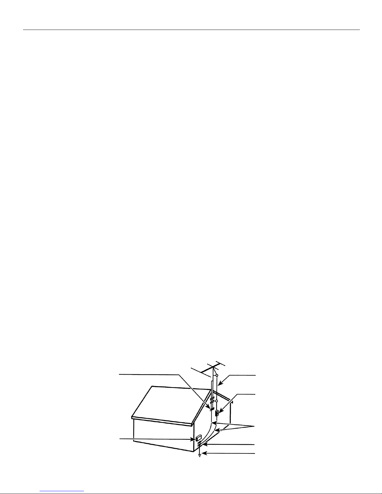
IF YOUR PRODUCT IS EQUIPPED WITH ANTENNA TERMINALS, and if an
outdoor antenna is connected, be sure the system is grounded so as to
provide some protection against voltage surge and built-up static charges.
An outdoor antenna should be located away from power lines.
IF PRODUCT IS TO BE CONNECTED TO A CATV SYSTEM, call the CATV
system installer’s attention to Article 820-40 of the NEC that provides
guidelines for proper grounding and, in particular, specifies that the cable
ground shall be connected to the grounding system of the building, as close
to the point of cable entry as practical.
•
•
•
•
•
•
•
Some of the following information may not apply to your particular product; however, as with any electronic product,
precautions should be observed during hanlding and use.
Ground Clamp
Antenna
Lead in Wire
Antenna
Discharge Unit
(NEC* Section 810-20)
Ground Conductors
(NEC* Section 810-21)
Ground Clamp
Power Service
Grounding Electrode System
(NEC* Art 250 Part H)
Electric Service
Equipment
Antenna Grounding According to the National Electrical Code
 Loading...