

Page 1
Q1K Owner’s Manual
Page 2

1
Product Overview
Ultra small in size and big on features, this small footprint high fidelity amplifier is an audio powerhouse.
Either as a standalone studio quality stereo amplifier, or as a part of a more complex multi channel system,
the Q
1K
is the system designer’s ideal solution.
One Q
1K
amplifier consists of two channels of 500W, including the option for a 1000W bridge mode. Audio
quality is studio class, which places the Q
1K
comfortably both at home, on the stage, or in the studio. As a
reference amplifier the Q
1K
is clean and transparent and its ultra-compact and fashionable appearance is
a space saver anywhere it is installed. In bridge mode the amplifier can also operate as a 70V line, 1000W
power amplifier. Ideal for distributed systems where high quality and stable high power is required.
Safety Precautions
• Please read the instructions in this section carefully before use.
• Ensure all instructions in this manual are observed as all information contained within is very important.
• It is also highly recommended that this manual is retained for future reference.
Safety Symbol & Message Conventions
The safety symbols described are used in this manual to prevent bodily injury and property damage which
could result from mishandling. Before operating this product, please read this manual first, in full so you
that you are thoroughly aware of any risks.
Indicates a potentially hazardous situation which, if
mishandled, could result in serious personal injury or death.
WARNING
Page 3

2
• When cleaning the unit, ensure it has been
disconnected from any power source and
that only a dry cloth is used. Do not use any
aerosol or liquid based cleaners.
• Ensure all electronics are electronically
grounded (earthed) to a safety ground terminal
in order to avoid electric shock. Do not ground
any device to a gas pipe as this may result in
fire.
• Servicing of all electronics should only be
carried out by a certified Quest technician.
Please consult your original place of purchase
to find the location of your nearest Quest
service centre.
• When installing amplifiers and\or other
electronics only use the hardware specifically
designed for this product.
• Do not expose the unit to any moisture
whether rain, water or other liquids. Exposure
to moisture could result in damage to internal
components or electrocution\circuit failure.
• Do not cut, kink, otherwise damage or modify
speaker cable. Ensure a speaker cable with
a core diameter of at least 1.5mm is used for
correct performance.
• Do not install or place speaker cables or
this device near heaters, high traffic areas or
any area where the cables or device can be
damaged.
• Avoid installing or mounting speaker boxes,
amplifiers, electronics or cabling in unstable
locations.
• In the event of storms and\or lightning, ensure
all devices are disconnected from mains
power in order to prevent damage to any of
the units in the system.
General Caution
Page 4
3
Amplifier Connections
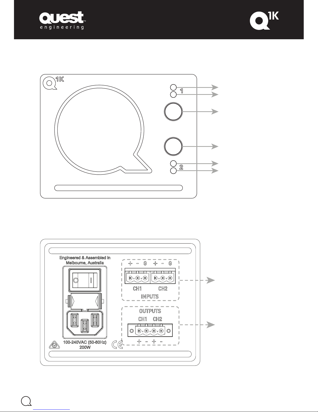
Front Panel Controls
Balanced Input Connectors
Plug: 2x 5.08mm 3-Way Captive Screw Plug
Speaker Output Connector
Plug: 5.08mm 4-Way Locking Captive Screw Plug
Figure 1.01
Channel 1 Clip Indicator
Channel 1 Signal Indicator
Channel 1 Level Control
Channel 2 Clip Indicator
Channel 2 Signal Indicator
Channel 2 Level Control
Figure 1.00
Page 5
4
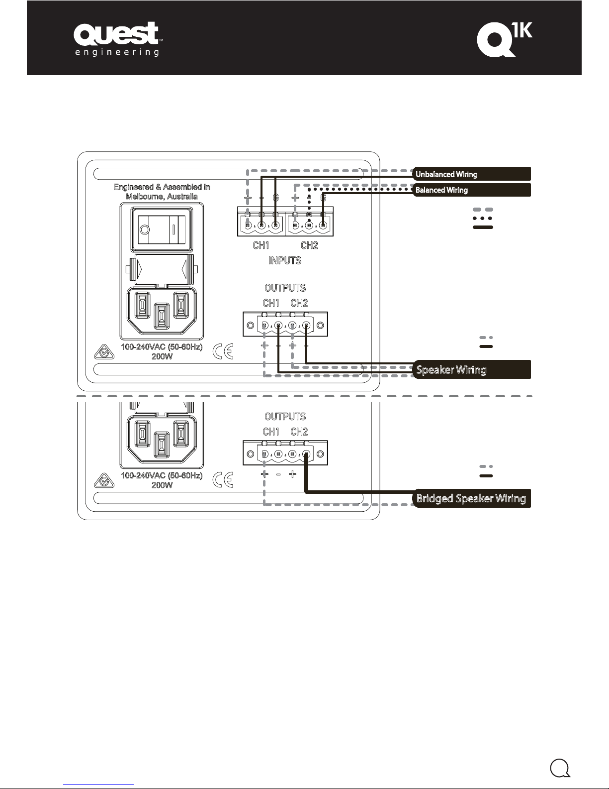
Amplier Wiring
Balanced Wiring
Unbalanced Wiring
Speaker Wiring
Balanced Wiring
Unbalanced Wiring
Bridged Speaker Wiring
+ Hot
- Cold
Ground
+ Positive
- Negative
+ Positive
- Negative
Figure 1.02
Page 6
5
Amplifier Operation
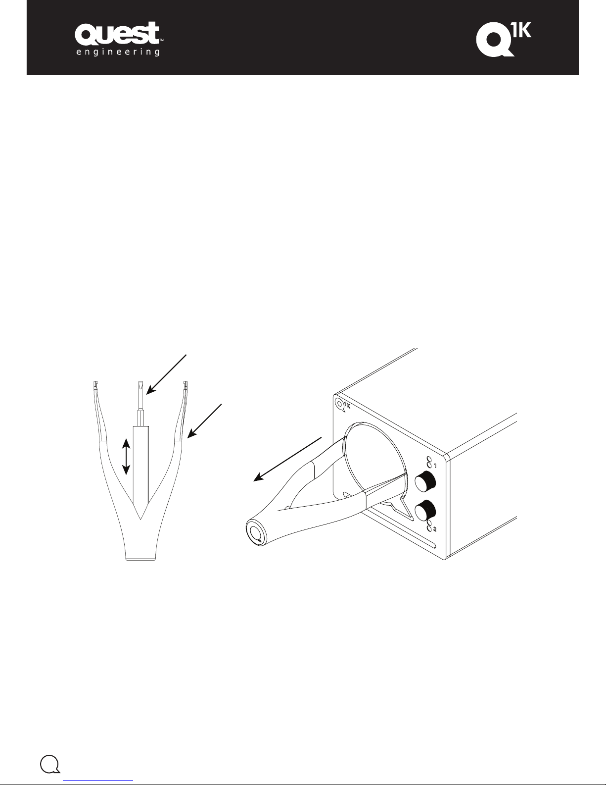
Behind the Q1K’s ‘Q’ device is an impressive selection of switchable functions. Simply remove the badge
(with the provided Quest TL02 tool), and an installer can configure a range of filter settings and amplifier
modes.
The ‘Q’ device also provides some security when it comes to setting selection, as it appears to be a fixed
item, and also requires the TL_02 to remove adds piece of mind to your installation.
Available are independent high pass filters either 35Hz or 85Hz, and independent 100Hz low pass filters.
All filters are 4th order Butterworth type. The filter selections are ideal for setting crossover points for
subwoofers, and mid-top boxes.
Other features include the ability to sum both input channels, bridge the amplifier, and ground lift input
signals. Front panel functions can also be selected including: Meters Mode, Auto Standby Enable, Front
Panel Lighting Dim, and Front Panel Lock.
The images below depict the tools that come with your Q
1K
; one TL_01 Screwdriver for DIP switch
operation and connector termination, and one TL_02 for ‘Q’ device removal.
Figure 1.03
TL_01
TL_02
Page 7
6
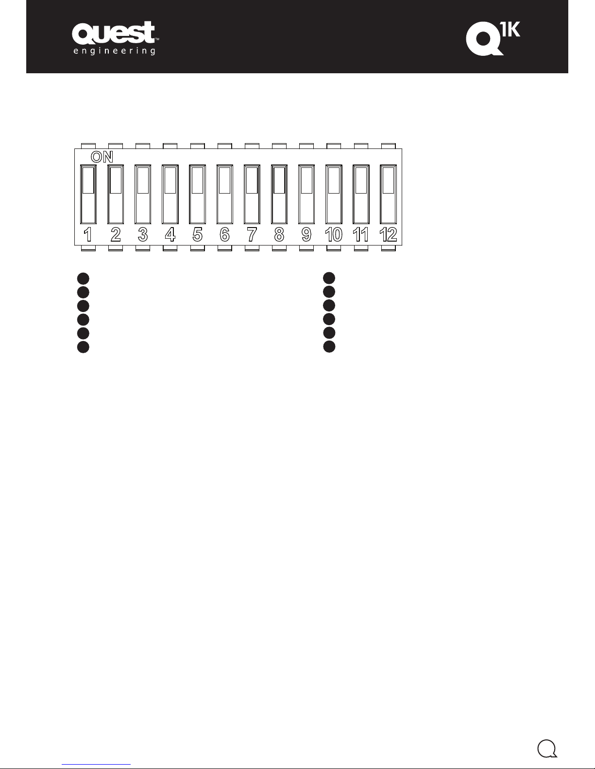
DIP Switch Settings
CH1 85Hz High Pass Filter1
2
3
4
5
6
CH1 100Hz Low Pass Filter
CH2 85Hz High Pass Filter
CH2 100Hz Low Pass Filter
Low Impedance Bridge Mode
(summed inputs - ganged gain controls)
High Impedance Bridge Mode (summed inputs - ganged gain controls)
DIP Switch Settings:
CH1 85Hz High Pass Filter
1
2
3
4
5
6
7
8
9
10
11
12
CH1 100Hz Low Pass Filter
CH2 85Hz High Pass Filter
CH2 100Hz Low Pass Filter
Low Impedance Bridge Mode
(summed inputs - ganged gain controls)
High Impedance Bridge Mode (summed inputs - ganged gain controls)
Summing Mode (summed inputs - individual gain controls)
Ground Lift
Meters Mode
Auto Sleep Enable
Dimmed Lighting Mode
Front Panel Lock
DIP Switch Settings:
Figure 1.04
1. 85Hz 4th order Butterworth High Pass Filter
for Channel 1 (when off the fixed 35Hz 4th order
Butterworth High Pass Filter is enabled).
2. 100Hz 4th order Butterworth Low Pass Filter for
Channel 1.
3. 85Hz 4th order Butterworth High Pass Filter
for Channel 2 (when off the fixed 35Hz 4th order
Butterworth High Pass Filter is enabled).
4. 100Hz 4th order Butterworth Low Pass Filter for
Channel 2.
5. Low Impedance Bridge Mode (Figure 1.06)
is used when bridging the amplifier for low
impedance loads (i.e. <8 Ω, non 70V loads). In
this mode the amplifier performs a soft-reboot,
mixes both input channels together, then channel
gains are ‘ganged’. Ganged channel gains
means that either rotary encoder will affect both
channels, and the ratio between each channel’s
gain remains the same. For example, if you set
Channel 2 to maximum, and Channel 1 to 50%
level then enable Low Impedance Bridge Mode –
both channel gain settings will remain the same
level apart no matter which rotary encoder is
operated. Remember to set individual levels prior
to enabling this mode.
6. High Impedance Bridged Mode (Figure 1.06)
is used for high impedance loads (i.e. 8Ω - 70V
loads). In this configuration, the channel gains are
‘ganged’ as they are in Low Impedance Bridge
Mode, and operate in the same way. Both input
channels are also mixed together. This mode also
allows for 70V operation.
7. Summing Mode (Figure 1.07) mixes both
input channels together, and channel gains are
individually controllable.
9. Meters Mode alters the operation of the
illuminated ‘Q’ Device, and uses them to display a
representation of both channel levels as a Meter.
10. Auto Sleep Enable allows the amplifier to enter
sleep mode 30 minutes without an input signal
(above the threshold for signal LEDs on the front
panel). Wake up time is ~3 seconds. Sleep Mode
complies with ErP (1275/2008/EC) < 0.5W mains
consumption.
11. Dimmed Lighting Mode sets the front panel ‘Q’
device illumination to a lower brightness.
12. Front Panel Lock disables the rotary encoders
and is useful when permanently installing the
product.
DIP Switch Functions in Detail
Page 8
7
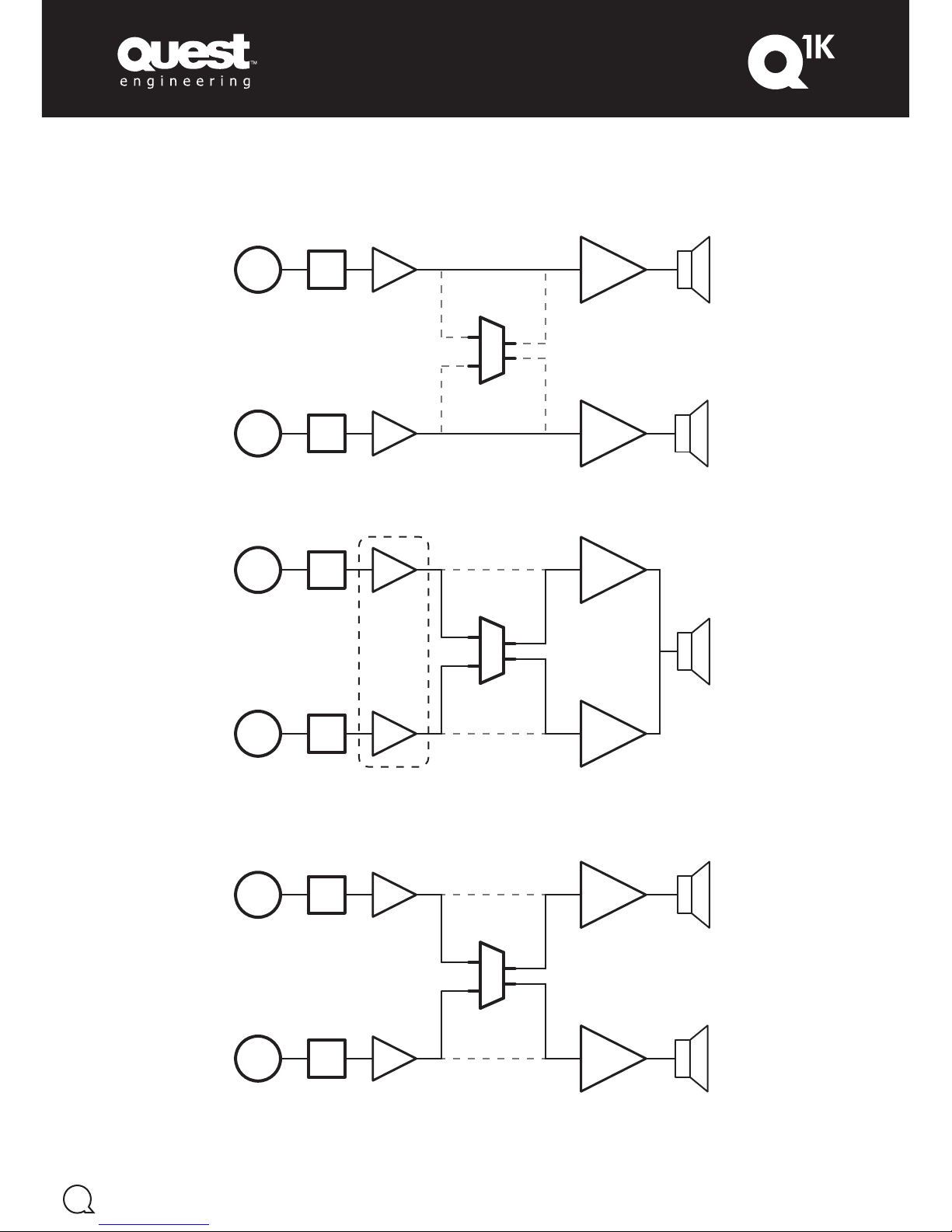
Amplifier Configurations
AMPLIFIER
1
AMPLIFIER
2
SUMMING
CIRCUIT
DCA
1
DCA
2
FILTERS
FILTERS
INPUT
1
INPUT
2
AMPLIFIER
1
AMPLIFIER
2
SUMMING
CIRCUIT
DCA
1
DCA
2
FILTERS
FILTERS
INPUT
1
INPUT
2
CONTROLS
LINKED
Figure 1.05 (Normal Dual Channel Mode)
Figure 1.06 (Bridged Mode (both low and high impedance variants))
AMPLIFIER
1
AMPLIFIER
2
SUMMING
CIRCUIT
DCA
1
DCA
2
FILTERS
FILTERS
INPUT
1
INPUT
2
Figure 1.07 (Summed Mode)
Page 9
8
Cooling and Ventilation
Air is drawn in from the front panel and passed out the rear panel. It is essential that while the amplifier
is running air is able to circulate around it freely. The efficiency of the cooling system will depend on the
immediate environment (e.g. an enclosed rack, direct sunlight).
If the amplifier is installed in a case, an open area at the front and back is required. This area should be in
line with the amplifier or large enough at the top of the amplifier location to allow passage of warm air to
escape. If this cannot be achieved a forced ventilation system should be used.
Note: Continuous mid to high power draw at low load impedance can cause more heat dissipate from the
amplifier.
Rack Mounting the Q1K as a Multi Channel Installation
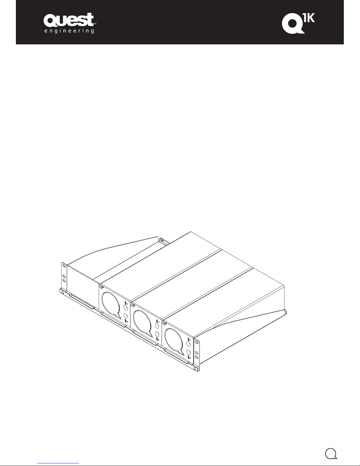
Each Q1K amplifier is a ¼ rack width wide, by 2RU high. Combined with the Universal Rack Kit (uRAK1) it
is possible to mount four Q
1K
amplifiers into a single 2RU space. Delivering 8x 500W, or 4x 1000W, or a
combination of both high and low impedance.
Figure 1.08 below shows a uRAK1 with three Q
1K
amplifiers, and a blanking plate installed in the first
position.
Figure 1.08
Page 10
* Quest Engineering reserves the right to make changes in specifications, or products without prior notice.
** The figures shown above are ‘real world’, usable specifications and are conservative as a result. Quest Engineering does not believe
in portraying misleading or exaggerated specifications.
9
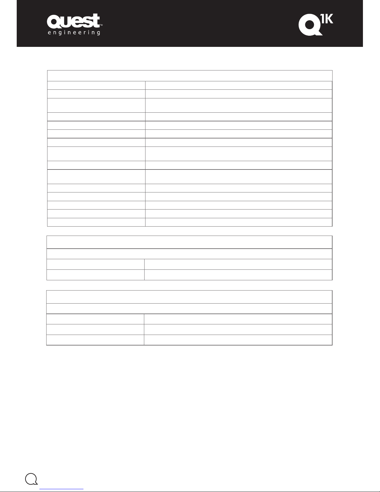
Specifications
Max. Output Voltage 70 Vp SE, 140 Vp BTL
Output Circuitry Class D
Signal To Noise-Ratio
(20Hz - 20kHz, 4Ω load MOL)
> 91 dB (unweighted)
THD+N (1W 1kHz) < 0,01 %
Dynamic Range 120 dBA
Frequency Response (4Ω, 120W output) 35Hz - 20kHz (fixed 35Hz 4th Order Butterworth High Pass Filter)
Gain 28dB
Protection Circuits
Temperature, Over Current, DC Output, Mains RMS Input, High Frequency, and
Internal Rail Over-voltage
Indicators Signal, Clip, Fault, Gain Settings, Meters Mode, (‘Q’ Illumination)
ErP (1275/2008/EC) compliant standby
consumption < 0.5W
< 0.5W
Mains Input Voltage 85VAC - 265VAC
Net Weight 3.1kg
Shipping Weight 4.3kg
Dimensions (HxWxD) 87 x 110 x 330mm
Shipping Dim. (HxWxD) 136 x 254 x 395mm
Stereo
All channels driven @ 1kHz, THD < 1%, 230VAC
8Ω 245 W
4Ω 490 W
Mono Bridge
Single channel driven @ 1kHz, THD < 1%, 230VAC
8Ω 900 W
4Ω 1050 W
70V 1050 W
Page 11

Page 12

www.questengineering.com.au
Register Your Product
Thank you for choosing Quest. Please take the
time to complete your product registration.
Registering your Quest Engineering product will:
• CONFIRM YOUR WARRANTY
• REGISTER YOUR PRODUCT
• PROTECT YOUR NEW PRODUCT
REGISTER ONLINE:
www.questengineering.com.au/registration
For spare parts and service, contact your local
authorised Quest Dealer.
 Loading...