

Page 1
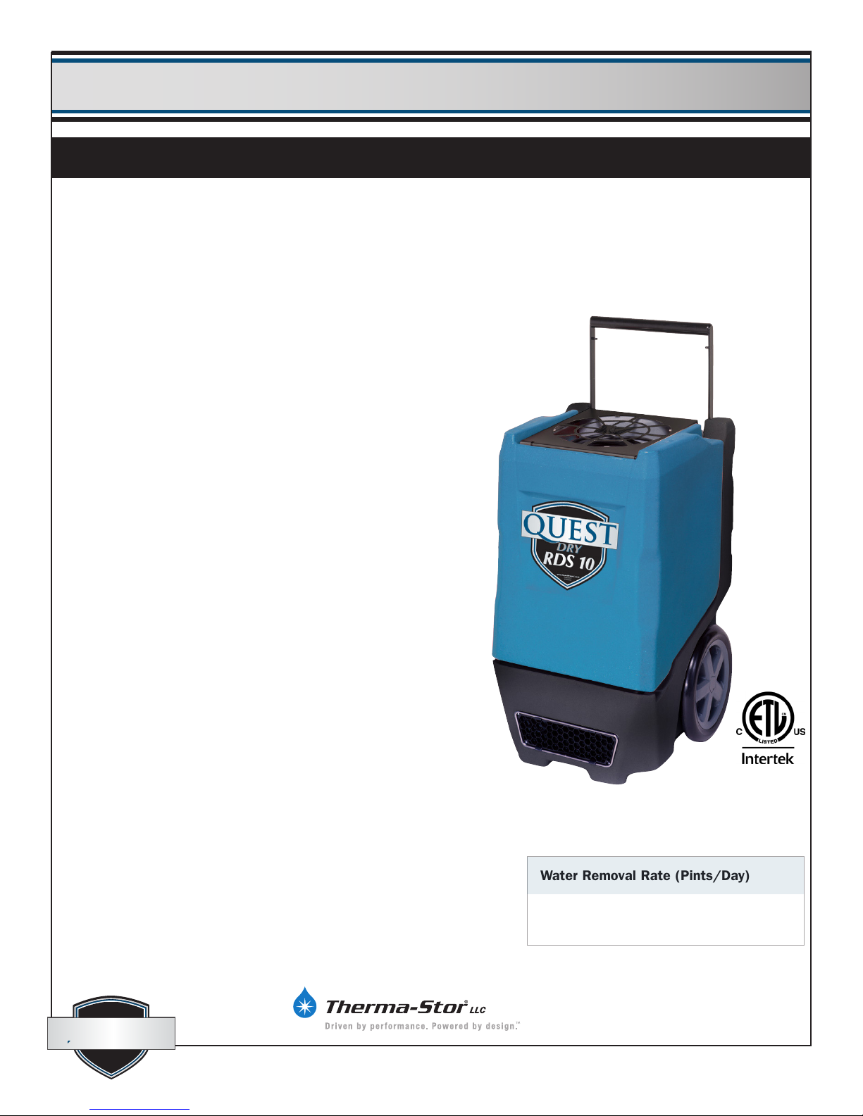
Quest DRY 150Quest Dry RDS 10
Installation, Operation and Maintenance InstructionsInstallation, Operation and Maintenance Instructions
– Read and Save These Instructions –
– Read and Save These Instructions –
This manual is provided to acquaint you with
the dehumidier so that installation, operation
and maintenance can proceed successfully.
Ultimate satisfaction depends on the quality
of installation and a thorough understanding
of this equipment. The dehumidier is built
around tested engineering principles and has
passed a thorough inspection for quality of
workmanship and function.
Quest Dry RDS 10:
• Roto-mold design
• 80 pints per day at 80ºF/60%RH (AHAM)
(10 Gallons)
• 5.1 amps of power
• 12-inch recessed wheels
• Telescoping handle
• Solid state control panel
• Multiple ducting options
• Stackable design
• Lightweight
Patent 7,246,503
Water Removal Rate (Pints/Day)
80 pints 80˚F, 60% (AHAM)
quest
quest
quest
quest
Specications subject to change without notice.
4201 Lien Rd Phone 608-237-8400
Madison, WI 53704 Toll-Free 1-866-933-7476
www.QuestOnTheJob.com [email protected]
1
4037498
04/15
Page 2

Quest Dry RDS 10 Installation, Operation and Maintenance Instructions
Quest Dry RDS 10 Installation, Operation and Maintenance Instructions
Table of Contents
Safety Precautions ............................................. 3
1. Safety Certications ....................................... 4
2. Specications ............................................... 4
3. Operation ..................................................... 4
3.1 Transporting ............................................ 4
3.2 Electrical Requirements ........................... 5
3.3 Condensate Removal ............................... 5
3.4 Ducting ................................................... 5
3.6 POWER Button ........................................ 5
3.7 PURGE Button ........................................ 5
3.8 Hour Meter ............................................. 6
3.9 HOURS Button ....................................... 6
3.10 DEFROST Light ..................................... 6
4. Maintenance ................................................. 6
4.1 Air Filter .................................................. 6
4.2 Storage .................................................... 6
5 . Service .......................................................... 7
5.1 Technical Description .............................. 7
5.2 Troubleshooting ................................... 7, 8
5.3 Air Mover ................................................ 9
5.4 Thermistor ............................................... 9
5.5 Condensate Pump ................................. 10
5.6 Float Safety Switch ................................ 10
6. Options and Accessories ............................. 10
7. Wiring Diagram .......................................... 11
8. Service Parts ................................................ 12
Warranty ......................................................... 13
quest
quest
1-866-933-7486
www.QuestOnTheJob.com
2
Page 3

Quest Dry RDS 10 Installation, Operation and Maintenance Instructions
Quest Dry RDS 10 Installation, Operation and Maintenance Instructions
Safety Precautions
Read the installation, operation and maintenance instructions carefully before installing and operating
this device. Proper adherence to these instructions is essential to obtain maximum benet from your
Quest Dry RDS 10.
READ AND SAVE THESE INSTRUCTIONS
• Never operate a unit with a damaged power cord. If
the power cord is damaged it must be replaced by the
manufacturer, its service agent, or similarly qualied person
in order to avoid a hazard.
• The unit shall be installed in accordance with national
wiring regulations.
• Do not obstruct the air intake and exhaust. Maintain a .3 m
(1 ft) clearance around the air intake and exhaust.
• This appliance is not intended for use by persons (including
children) with reduced physical, sensory or mental
capabilities, or lack of experience and knowledge, unless
they have been given supervision or instruction concerning
use of the appliance by a person responsible for their safety.
Children should be supervised to ensure that they do not
play with the appliance.
quest
quest
www.QuestOnTheJob.com
3
Page 4
Quest Dry RDS 10 Installation, Operation and Maintenance Instructions
Quest Dry RDS 10 Installation, Operation and Maintenance Instructions
1. Safety Certications
The Quest Dry RDS 10 conforms to unied standard UL 60335-2-40.
2. Specications
Part No. 4029630
Power 5.1 amps, 110-120 VAC, Grounded
Water 80 pints/day @ AHAM (80°F, 60%)
Removal (10 Gallons)
Blower 230 CFM without external ducting
210 CFM @ .15 IWG external static
Refrigerant 1 lb, 6 oz. R410A
Charge
Operating 33°F to 105°F
Range
Filters: 12” x 12” x 1” Pleated Media MERV-8
Duct Intake – 12” Flex-Duct
Options Supply – 10” Lay-Flat
Warranty Five years;
1st year 100% of Parts and Labor
2nd-5th year 100% of Parts of sealed
refrigeration system.
Dimensions Width 20”, Depth 20”, Height 33”
Weight 105 lbs.
Patent 7,246,503
3. Operation
Place dehumidier inside structure, place condensate hose into a drain, or a very large
container, and turn on. To decrease drying times, make sure all windows and doors are
closed to the outside and seal off the wet area from any unaffected areas.
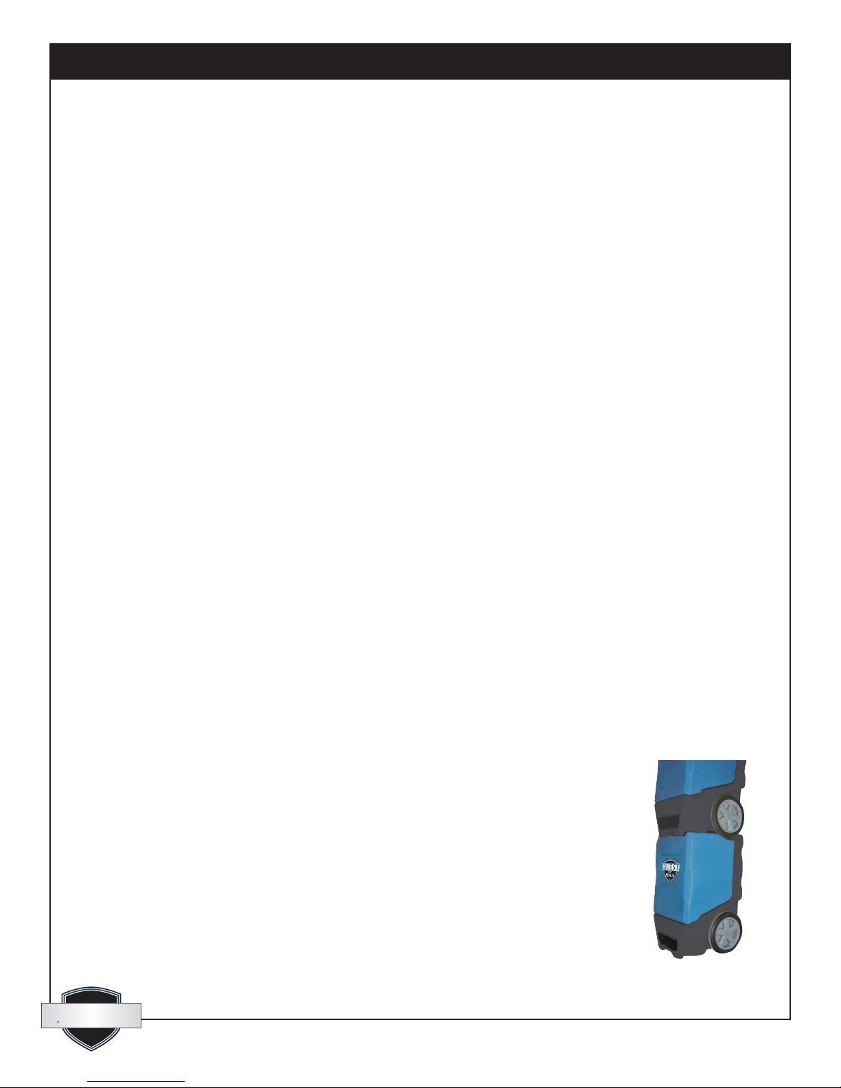
3.1 Transporting
The Quest Dry RDS 10 features a high-impact roto-molded housing which protects the
unit airways, and while loading into vehicles. The unit was designed to make it easy to
stack two high. The wheels of the top unit stack in the indentations of the bottom unit to
provide stability. It is recommended the units are properly secured for transport. The Quest
Dry RDS 10 must always be upright when transported by vehicle. It may be tipped onto its
handle and back for loading and moving by hand.
Figure 1: Quest
Dry RDS 10
quest
quest
1-866-933-7486
www.QuestOnTheJob.com
4
Page 5
Quest Dry RDS 10 Installation, Operation and Maintenance Instructions
Quest Dry RDS 10 Installation, Operation and Maintenance Instructions
3.2 Electrical Requirements
The Quest Dry RDS 10 plugs into a common grounded outlet on a 15 amp circuit. It draws 5.1 amps at 80°F,
60% RH. If used in a wet area, a ground fault interrupter (GFI) is required. If an extension cord is required, it
must have a minimum of 14 gauge conductors if 25 feet long or less and 12 gauge conductors if greater than
25 feet long.
3.3 Condensate Removal
The Quest Dry RDS 10 is equipped with an internal condensate pump to remove the water that is condensed
during dehumidication. This allows the condensate to be pumped 20 feet with the attached hose. If the
condensate must be pumped more than 20 feet above the unit, a second pump must be added to relay the
condensate. The condensate pump automatically purges for 20 seconds every eight minutes. Use the PURGE
button to manually remove condensation.
3.4 Ducting
A wire duct collar is supplied to allow 10” lay-at duct to be attached to the Quest Dry RDS 10 outlet. Lay-
at plastic ducting is available; see accessories table page 6. To attach ducting to the wire duct collar, put
the plastic duct end through the collar center and roll the duct end outward so that it overlaps the outside of
the collar. The duct and collar may then be quickly attached to the Quest Dry RDS 10 by snapping the collar
over the four exhaust tabs.
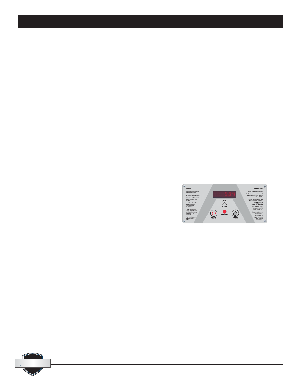
3.5 Defrost Cycle
If the low side refrigerant temperature drops due to excessive frost
formation on the evaporator coil and below the temperature set
point, the thermistor activates the solid-state control and defrost
light. The compressor is cycled off and on by the thermistor
temperature measurement. The air mover will continue to run,
causing air to ow through the evaporator coil and melt the ice
when the compressor is off. When the air temperature and/or
humidity increases, the evaporator temperature will rise and the
thermistor will end the defrost cycle at the temperature set point.
Figure 2: Quest Dry RDS 10 control board.
3.6 POWER Button
Press the POWER button to turn the dehumidier on or off. When starting the dehumidier the display will
show the accumulated hours. Press the POWER button again to turn the dehumidier off. The display will
also power off.
3.7 PURGE Button
During normal operation the pump automatically cycles every four minutes. Press the PURGE button to
remove condensate manually from the reservoir. There are several ways to manually remove water from the
reservoir:
1. Press the PURGE button once and the pump will run for 20 seconds
2. Press and hold the PURGE button and the pump will run for up to 30 seconds
3. Press the PURGE button while the dehumidier is powered off and the pump will run for 30 seconds.
Always manually purge the water reservoir before transport or storage. Turn off the power and allow the
plugged in dehumidier to rest 15 minutes before the nal purge.
quest
quest
1-866-933-7486
www.QuestOnTheJob.com
5
Page 6

Quest Dry RDS 10 Installation, Operation and Maintenance Instructions
Quest Dry RDS 10 Installation, Operation and Maintenance Instructions
3.8 Hour Meter
The digital hour meter displays the amount of time the dehumidier has been turned on to the tenth of an
hour. The hour meter continuously cycles between total machine hours and job hours every 3 seconds.
Hours are stored in memory even when the unit is unplugged. The previous totals will be displayed next
time the unit is powered on.
3.9 HOURS Button
Pressing the HOURS button displays the hour meter when the unit is turned off but plugged into power. To
reset job hours, press and hold the HOURS button for 5 seconds when the unit is operating.
3.10 DEFROST Light
The DEFROST light turns on when the unit is in defrost cycle and indicates when the compressor is off.
4. Maintenance
4.1 Air Filter
The Quest Dry RDS 10 is equipped with a pleated media air lter that must be checked regularly. The
standard lter is a MERV-8 high efciency lter. Operating the unit with a dirty lter will reduce the
dehumidier’s capacity and efciency and may cause the compressor to cycle off and on unnecessarily. The
lter can generally be vacuumed clean several times before needing replacement. Replacement lters can be
ordered from the manufacturer or purchased locally if available.
IMPORTANT: DO NOT operate the unit without the lter or with a less effective lter as the heat
exchanger and coils inside the unit could become clogged and require disassembly to clean.
4.2 Storage
There are two issues to consider when the Quest Dry RDS 10 is stored between uses and both pertain to the
water trapped in the unit: damage caused by freezing or biological growth. The effect of the trapped water
can be greatly reduced if precautions are taken to remove as much as possible before storage.
1. Use the pump PURGE button to reduce the water level in the reservoir
2. Walk out the hose to drain it completely
In order to reduce biological growth ush the unit with a biofungicide that is approved for use with
copper, aluminum, polyethylene and ABS. To ush:
1. Run the hose to a drain
2. Plug in the unit but do not turn it on
3. Remove the air lter. Slowly pour a pint of the chemical through the top so that it drains into the heat
exchanger
4. Use PURGE button to remove chemicals in reservoir. Run PURGE until hose runs dry
5. Walk out hose to drain completely
6. Replace air lter
quest
quest
1-866-933-7486
www.QuestOnTheJob.com
6
Page 7
Quest Dry RDS 10 Installation, Operation and Maintenance Instructions
Quest Dry RDS 10 Installation, Operation and Maintenance Instructions
5. Service
WARNING: Servicing the Quest Dry RDS 10 with its high pressure refrigerant system and high voltage
circuitry presents a health hazard which could result in death, serious bodily injury, and/or property
damage. Only qualied service people should service this unit.
CAUTION: Do not operate unit without the front housing in place.
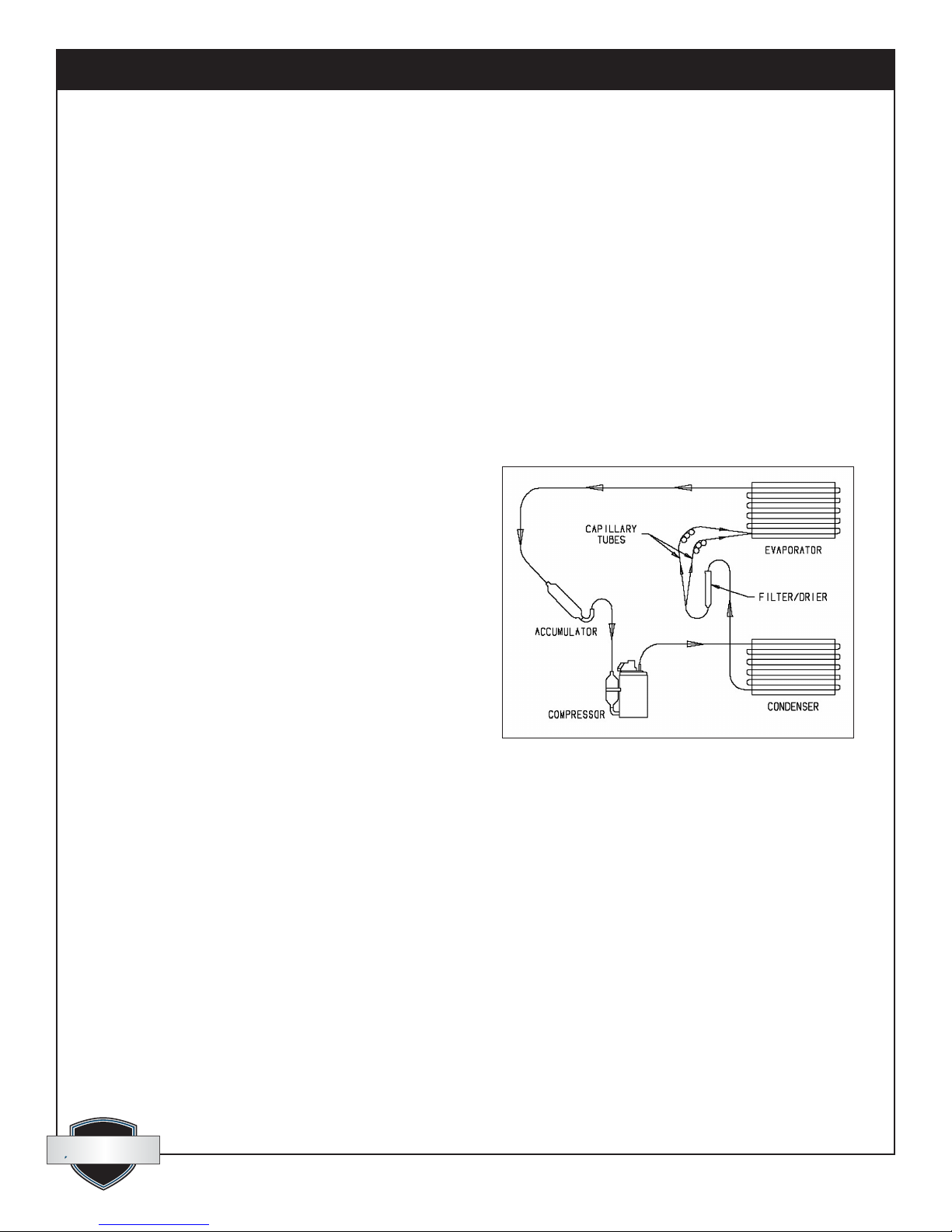
5.1 Technical Description
The Quest Dry RDS 10 uses a refrigeration system similar to an air conditioner’s to remove heat and moisture
from incoming air and to add heat to the air that is discharged.
Hot, high pressure refrigerant gas is routed from the compressor to the condenser coil. The refrigerant is
cooled and condensed by giving up its heat to the air that is about to be discharged from the unit. The
refrigerant liquid then passes through a lter/drier and capillary tubing which cause the refrigerant pressure
and temperature to drop. It next enters the evaporator coil where it absorbs heat from the incoming air and
evaporates.
The evaporator operates in a ooded condition,
which means that all the evaporator tubes contain
liquid refrigerant during normal operation. A ooded
evaporator should maintain constant pressure and
temperature across the entire coil, from inlet to outlet.
The mixture of gas and liquid refrigerant enter the
accumulator after leaving the evaporator coil. The
accumulator prevents any liquid refrigerant from
reaching the compressor. The compressor evacuates
the cool refrigerant gas from the accumulator and
compresses it to a high pressure and temperature to
repeat the process.
5.2 Troubleshooting
No dehumidication, neither hour meter display nor compressor run and POWER button does not turn
ON.
1. Unit unplugged or no power to outlet
2. Defective control board
3. Loose connection in internal wiring
No dehumidication, neither hour meter display nor compressor run with POWER button ON.
1. Defective control board
2. Loose connection in internal wiring
quest
quest
www.QuestOnTheJob.com
7
Page 8

Quest Dry RDS 10 Installation, Operation and Maintenance Instructions
Quest Dry RDS 10 Installation, Operation and Maintenance Instructions
Some dehumidication, air mover runs continuously but compressor only runs sporadically.
1. Unit is in defrost cycle, DEFROST light on
2. Defrost thermistor defective or loose
3. Loose connection in compressor circuit
4. Defective compressor overload
5. Defective compressor
6. Defective relay
7. Upper housing is not sealed to lower housing
No dehumidication, air mover runs but compressor does not.
1. Bad connection in compressor circuit
2. Safety oat switch closed, check pump reservoir
3. Defective compressor capacitor
4. Defective compressor overload
5. Defective compressor
6. Defective control board
Air mover does not run. Compressor runs briey but cycles on and off.
1. Loose connection in blower circuit
2. Obstruction prevents impeller rotation
3. Defective air mover
Unit removes some water but not as much as expected.
1. Air temperature and/or humidity have dropped
2. Humidity meter and/or thermometer used are out of calibration
3. Unit has entered defrost cycle
4. Air lter dirty
5. Defective defrost thermistor
6. Low refrigerant charge
7. Air leak such as loose cover
8. Defective compressor
9. Restrictive exhaust or inlet ducting
Unit runs but does not pump water.
1. Hose kinked or plugged
2. Pump motor defective
3. Pump check valve plugged
4. Bad connection in pump circuit
5. Hose disconnected internally
6. Defective control board (pump phase)
quest
quest
quest
quest
1-866-933-7486
www.QuestOnTheJob.com
8
Page 9
Quest Dry RDS 10 Installation, Operation and Maintenance Instructions
Quest Dry RDS 10 Installation, Operation and Maintenance Instructions
Unit pumps water automatically but not when PURGE button is pushed.
1. Bad connection in PURGE button circuit
2. Defective control board
Evaporator coil frosted continuously, low dehumidifying capacity.
1. Defrost thermistor loose or defective
2. Low refrigerant charge
3. Dirty air lter or restricted air ow
4. Upper housing is not sealed to lower housing
Compressor runs with POWER button OFF.
1. Defective relay
2. Defective control board
3. Upper housing not sealed to tower
5.3 Air Mover
The motorized impeller has a PSC motor and internal thermal overload protection. If defective, the complete
assembly must be replaced.
1. Unplug power cord
2. Remove the four screws attaching the bottom plate to the lower housing
3. Disconnect the impeller leads
4. Remove the four screws holding the impeller to the bottom plate
5. Reassemble the new impeller using the above procedure in reverse
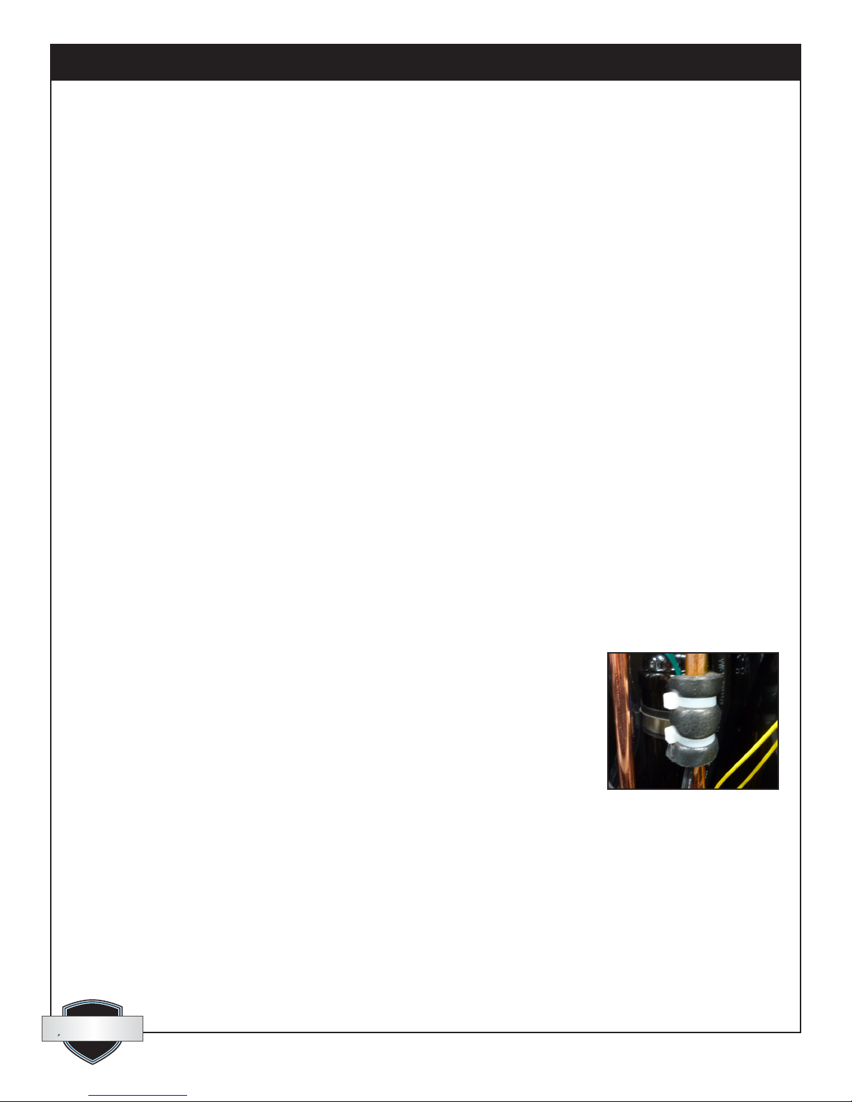
5.4 Thermistor
The defrost thermistor is attached to the refrigerant suction line between the accumulator and the evaporator.
To replace thermistor:
1. Unplug the dehumidier
2. Remove the front housing
3. Cut cable ties and remove insulation and aluminum tape.
4. Remove control panel
5. Unthread thermistor from control housing grommet
6. Detach thermistor from control board jumper
7. Reassemble thermistor and dehumidier using the above procedure in reverse
Figure 4: Thermistor attached
to the refrigerant line.
quest
quest
1-866-933-7486
www.QuestOnTheJob.com
9
Page 10
Quest Dry RDS 10 Installation, Operation and Maintenance Instructions
Quest Dry RDS 10 Installation, Operation and Maintenance Instructions
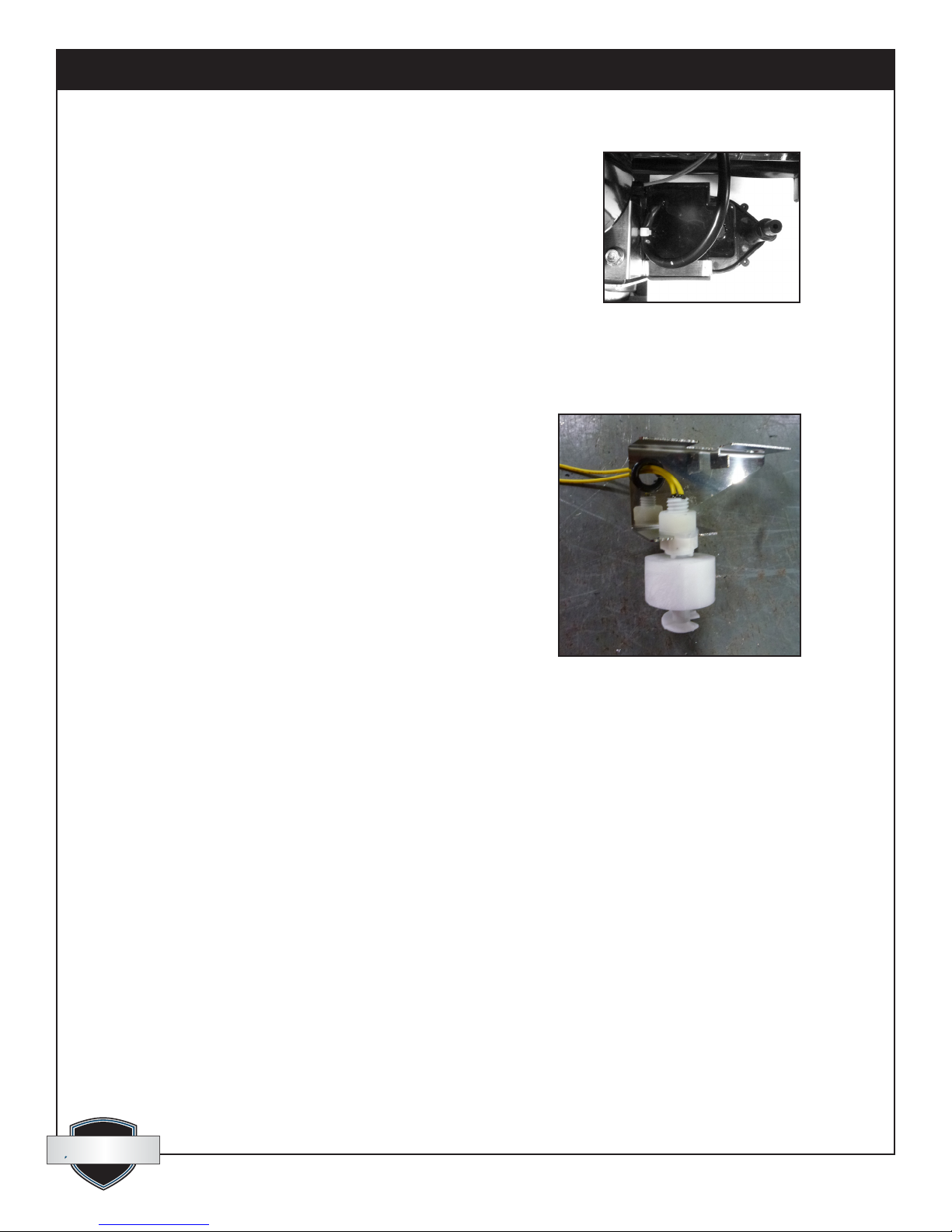
5.5 Condensate Pump
The internal condensate pump removes water that collects in the
reservoir.
To replace the condensate pump:
1. Unplug the unit
2. Remove the front housing
3. Unplug the pump wires from the wire harness
4. Remove the condensate hose and the one screw attaching the pump
bracket to the compressor support
5. Replace the pump, hose, wiring, bolts, and housing in the reverse order
Figure 5: Picture of pump and
oat switch brackets screw.
5.6 Float Safety Switch
The oat safety switch activates when the water rises too high
in the condensate reservoir. The oat safety switch turns off the
compressor until the water level lowers and disengages the switch.
To replace the oat safety switch
1. Unplug the dehumidier
2. Remove the front housing
3. Unplug the oat safety switch wires from the wire harness
4. Remove the one screw attaching the pump and oat switch
bracket to the compressor support
5. Remove the pump from the reservoir and slide out the oat
switch from under the compressor support
6. Replace the oat, pump, wiring, bolts and housing in the
reverse order
6 Options & Accessories
4026315 Air Filter, Pleated 12: x 12” x 1” MERV-8 (Standard)
4029499 Air Filter, Pleated 12” x 12” x 1” MERV-11
4029521 Intake Flex Duct 12” x 25” Metallize Polyester
4029252 Lay-Flat Duct 10” Round x 250’ Roll
To order, contact Therma-Stor LLC at 1-866-933-7486.
Figure 6: Picture of the oat safety switch
quest
quest
1-866-933-7486
10
www.QuestOnTheJob.com
Page 11
Quest Dry RDS 10 Installation, Operation and Maintenance Instructions
BLU-14
RED-13
COMPRESSOR
BLOWER MOTOR
LEVEL
SWITCH
CONTROL
BOARD
THERMISTOR
CONDENSATE PUMP
WHT-10
GRN
BLK
WHT-2
YEL-9
YEL-8
RUN
CAPACITOR
RUN
CAPACITOR
BLK-3
YEL-7
E1
E3
E2
E5
E4
BLK-5
BRN-6
BLK-12
BLU-18
BLK-4
WHT
S
R
C
Quest Dry RDS 10 Installation, Operation and Maintenance Instructions
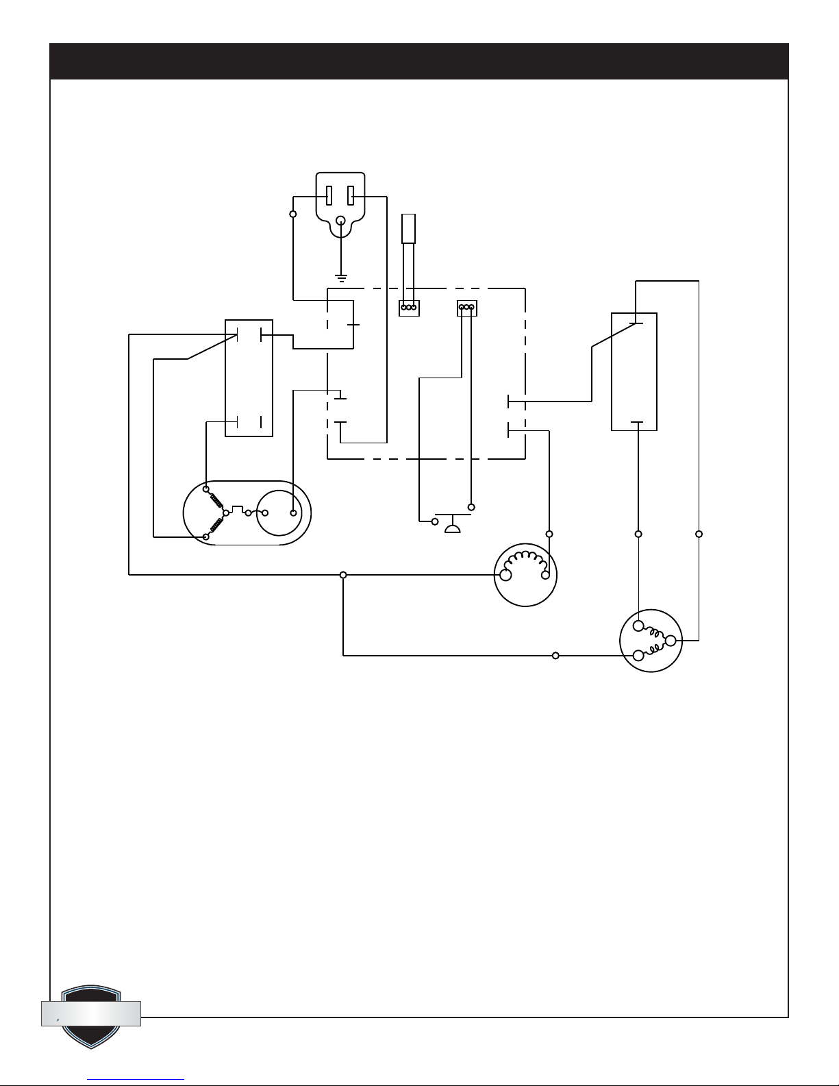
7. Wiring Diagram
Figure 7
quest
quest
1-866-933-7486
11
www.QuestOnTheJob.com
Page 12
Quest Dry RDS 10 Installation, Operation and Maintenance Instructions
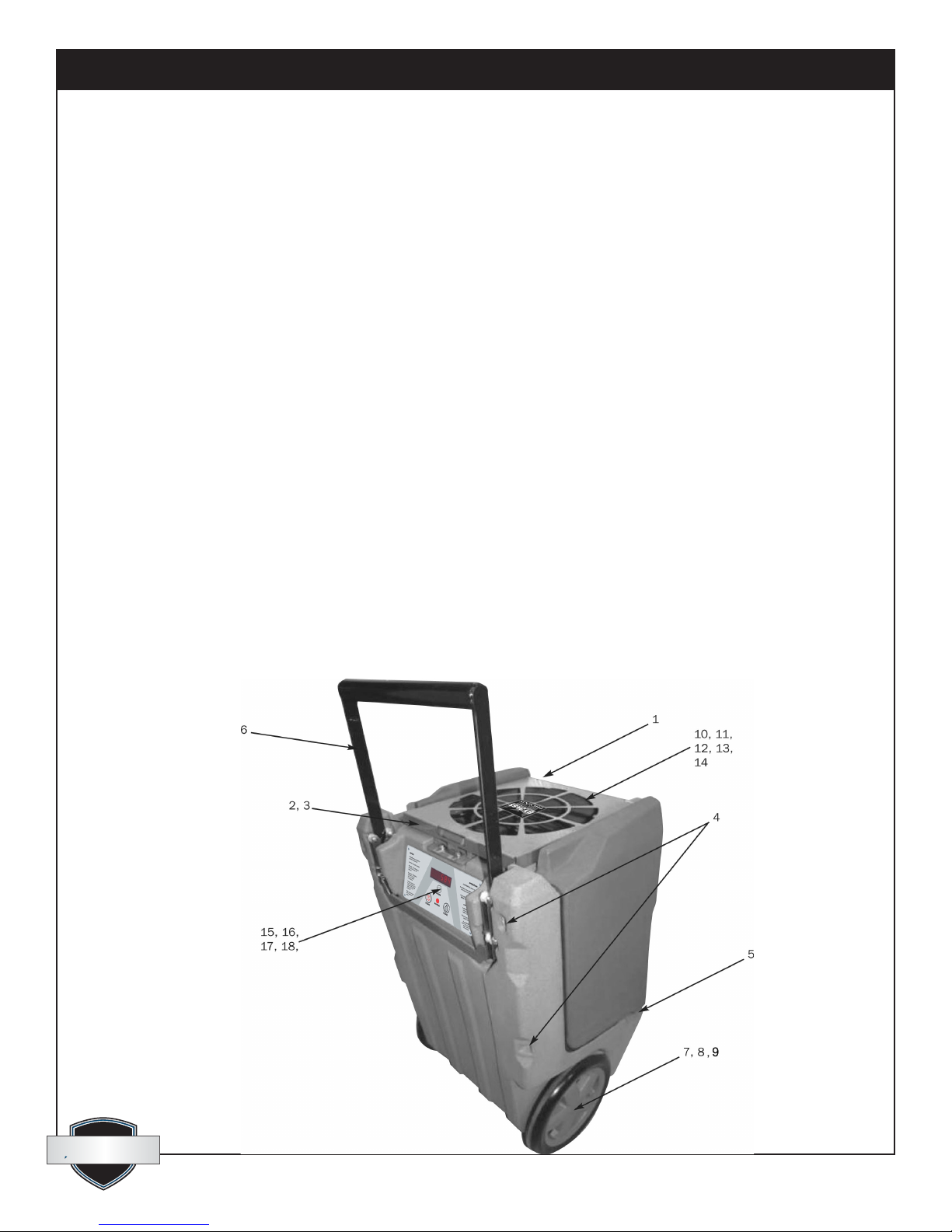
8. Service Parts
Item Description Qty Part No.
1 Top Cover 1 4026977
2 Top Cover Hinge 2 4026978
3 Top Cover Catch 1 4026979
4 Hex Bolts, 1/4”–20 x 4” 4 1154019
5 Hex Bolts, 1/4”–20 x 1.75” 2 1154014
6 Handle Assembly 1 4027381
7 Wheel, 12” 2 4026851
8 Cotter Pin 2 1284404
9 Hub Cap, Wheel 2 4027138
10 Filter, 12” x 12” x 1” 1 4026315
11 Hose (1/4” ID x 33’ long) 1 4024916
12 Coupling Body, 1/4” Tube 1 4026306
13 Coupling Insert, 1/4” Tube 1 4026986
14 Cord 1 4032297
15 Control Board 1 4026763
16 Capacitor, Compressor, 35 μF 1 4033032-03
Items listed are not shown
Description Qty Part No.
Compressor 1 4029567
Evaporator Coil 1 4028234
Condenser Coil 1 4028235
Accumulator 1 4028297
Condensate Pump 1 4034832
Float Safety Switch 1 4034374
Impeller, Air Mover 1 4026360
Exhaust Grill 1 4026308
Wire Duct Collar 1 4026309
Impeller Plate Bolt 4 1154006
17 Capacitor, Impeller, 7.5 μF 1 4033031-04
18 Thermistor 1 4031279
quest
quest
1-866-933-7486
12
www.QuestOnTheJob.com
Page 13

Quest Dry RDS 10 Installation, Operation and Maintenance Instructions
Quest Dry RDS 10 Installation, Operation and Maintenance Instructions
Quest Dry RDS 10 Limited Warranty
Warrantor:
Therma-Stor LLC
4201 Lien Rd
Madison, WI 53704
Telephone: 1-866-933-7486
Who Is Covered: This warranty extends only to the original end-user of the Quest Dry RDS 10
dehumidier, and may not be assigned or transferred.
Year One: Therma-Stor LLC warrants that, for one (1) year the Quest Dry RDS 10 dehumidier will operate
free from any defects in materials and workmanship, or Therma-Stor LLC will, at its option, repair or replace
the defective part(s), free of any charge.
Year(s) Two Through Five: Therma-Stor LLC further warrants that for a period of ve (5) years, the condenser,
evaporator, and compressor of the Quest Dry RDS 10 dehumidier will operate free of any defects in
material or workmanship, or Therma-Stor LLC, at its option, will repair or replace the defective part(s),
provided that all labor and transportation charges for the part(s) shall be borne by the end-user.
Year(s) One Through Seven: Materials and workmanship of the housing are covered.
End-User Responsibilities: Warranty service must be performed by a Servicer authorized by Therma-Stor
LLC. If the end-user is unable to locate or obtain warranty service from an authorized Servicer, he should
call Therma-Stor LLC at the above number and ask for the Therma-Stor Service Department, which will then
arrange for covered warranty service. Warranty service will be performed during normal working hours.
The end-user must present proof of purchase (lease) upon request, by use of the warranty card or other
reasonable and reliable means. The end-user is responsible for normal care. This warranty does not cover any
defect, malfunction, etc. resulting from misuse, abuse, lack of normal care, corrosion, freezing, tampering,
modication, unauthorized or improper repair or installation, accident, acts of nature or any other cause
beyond Therma-Stor LLC’s reasonable control.
Limitation and Exclusions: If any Quest Dry RDS 10 Dehumidier part is repaired or replaced, the new part
shall be warranted for only the remainder of the original warranty period applicable thereto (but all warranty
periods will be extended by the period of time, if any, that the Quest Dry RDS 10 Dehumidier is out of
service while awaiting covered warranty service).
UPON THE EXPIRATION OF THE WRITTEN WARRANTY APPLICABLE TO THE Quest Cool ACS 12 OR
ANY PART THEREOF, ALL OTHER WARRANTIES IMPLIED BY LAW, INCLUDING MERCHANTABILITY
AND FITNESS FOR A PARTICULAR PURPOSE, SHALL ALSO EXPIRE. ALL WARRANTIES MADE BY
THERMA-STOR LLC ARE SET FORTH HEREIN, AND NO CLAIM MAY BE MADE AGAINST THERMA-STOR
LLC BASED ON ANY ORAL WARRANTY. IN NO EVENT SHALL THERMA-STOR LLC, IN CONNECTION
WITH THE SALE, INSTALLATION, USE, REPAIR OR REPLACEMENT OF ANY Quest Cool ACS 12 OR PART
THEREOF BE LIABLE UNDER ANY LEGAL THEORY FOR ANY SPECIAL, INDIRECT OR CONSEQUENTIAL
DAMAGES INCLUDING WITHOUT LIMITATION WATER DAMAGE (THE END-USER SHOULD TAKE
PRECAUTIONS AGAINST SAME), LOST PROFITS, DELAY, OR LOSS OF USE OR DAMAGE TO ANY REAL
OR PERSONAL PROPERTY.
Some states do not allow limitations on how long an implied warranty lasts, and some do not allow the
exclusion or limitation of incidental or consequential damages, so one or both of these limitations may not
apply to you.
Legal Rights: This warranty gives you specic legal rights, and you may also have other rights which vary
from state to state.
quest
quest
1-866-933-7486
13
www.QuestOnTheJob.com
 Loading...