

Page 1
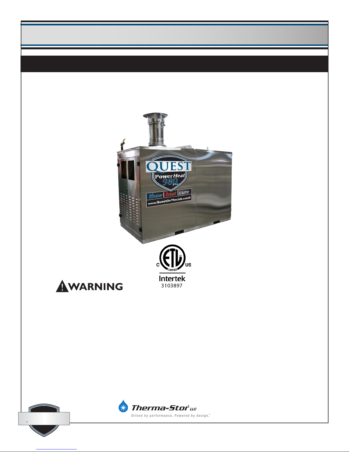
Quest Oil-Fired CHH-980
Installation, Operation and Maintenance Instructions
Installation, Operation and Maintenance Instructions
– Read and Save These Instructions –
– Read and Save These Instructions –
This appliance is equipped with a Blocked-Flue shutoff device. If any part of the ue-
gas passageway in the combustion chamber, exhaust pipe or rain cap should become
blocked or adversely restricted, a pressure sensing switch (Fig.27 pg.11) will break the
electrical control circuit and not allow the burner to run. There is a “Manual Reset”
button on this switch that will have to be reset before re-ring can occur. If the burner
fails to start after resetting once, call a qualied service technician to clean the ue
passageways and/or replace the switch. Cleaning instructions can be found in Section
(6.1 G) of the Maintenance section of this manual.
quest
quest
Specications subject to change without notice.
4201 Lien Rd. Phone 608-237-8400
Madison, WI 53704 Toll-Free 1-866-413-5214
www.QuestProtect.com [email protected]
1
TS-767
07/12
Page 2

Quest Oil Fired CHH-980 Installation, Operation and Maintenance Instructions
Table of Contents
1. System Description & Features .............................3
1.1 Description ....................................................3
1.2 Features .........................................................4
2. Safety ................................................................... 4
2.1 General Safety Guidelines .............................. 4
2.2 Safety Devices and Clearances ...................... 4
2.3 Heat Transfer Fluid .........................................5
3. Specications ....................................................... 5
3.1 Construction Specications ............................ 5
3.2 Dimensions & Capacities ............................... 6
3.3 Oil Burner & Fuel Specications .................... 6
3.4 Circulation Pumps ..........................................7
3.5 Electrical Requirements for Complete System . 8
3.6 Gauges & Indicator Lights .............................. 8
3.7 Controls & Electrical ......................................9
3.8 Control, Switches, & Gauges Identication ..10
4. Setup .................................................................. 12
4.1 Positioning Equipment on the job ................. 12
4.2 Hose & Accessory Connections .................... 12
4.3 Filling the Fluid System ................................15
4.4 Eliminating Air from the HTF Circuit ............16
4.5 Normal 2-Pump Mode with Full Load .......... 16
4.6 Normal 1-Pump Mode with Light Load ........ 17
4.7 Pump-assisted Chamber Draining ................17
4.8 Oil Burner Installation and Setup .................18
5. Operation ........................................................... 18
5.1 Startup .........................................................18
5.2 Shutdown .....................................................19
6. Maintenance ...................................................... 19
6.1 Service Instructions & Checks ......................19
6.2 Maintenance Frequency Chart ......................23
7. Troubleshooting .................................................24
7.1 Fault Determination .....................................24
7.2 Burner Internal Faults ...................................26
7.3 Electrical Schematics ....................................27
Warranty ............................................................30
Page
Serial No. _______________________________
Purchase Date ___________________________
Dealer’s Name ___________________________
quest
quest
1-866-413-5214
www.QuestProtect.com
2
Page 3
Quest Oil Fired CHH-980 Installation, Operation and Maintenance Instructions
1. System Description & Features
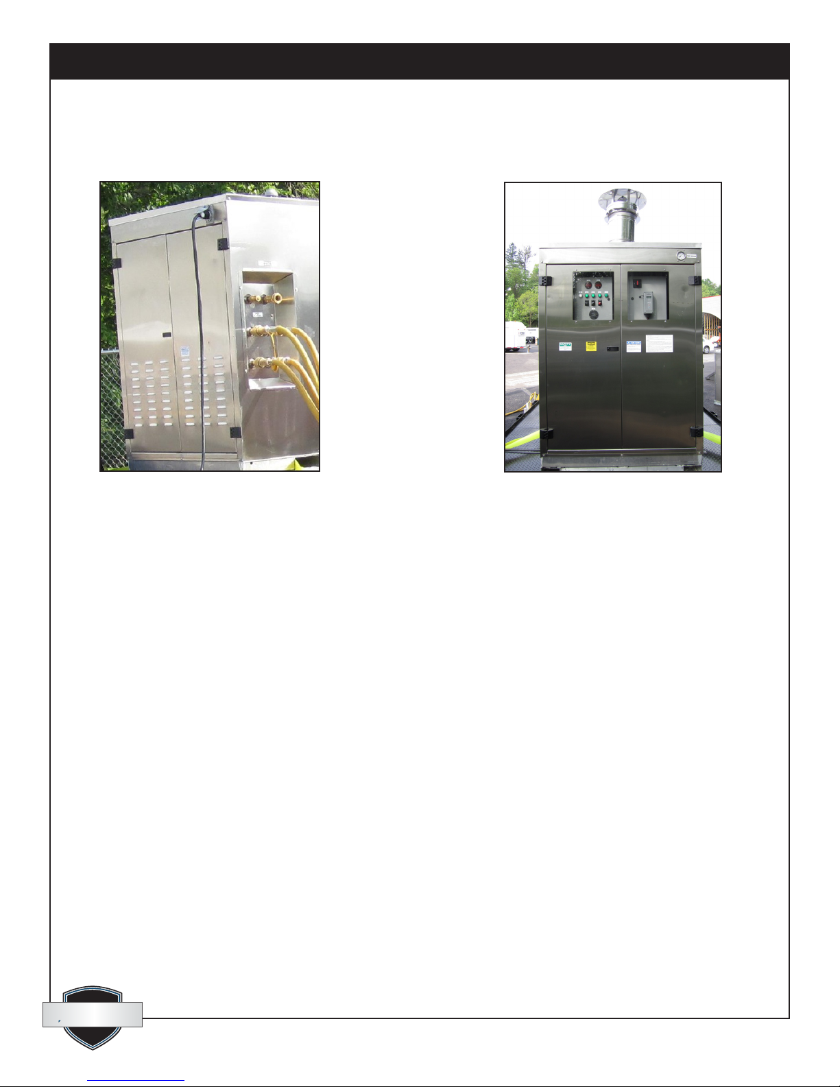
2: CHH-980, Burner End1: CHH-980, Pump End
1.1 Description
• The CHH-980 is a fuel burning appliance, designed to heat uid “on demand” and provide pumped
circulation of the uid for use in various portable hydronic applications.
• The CHH-980 provides a central source of hot “Heat Transfer Fluid” (HTF) for use with dependent heat
exchangers such as:
-Fan coils for heating and drying of structures.
-Multi-circuit line heat exchange hose or tubing for ground thawing, concrete
curing, snow melting and slab heating.
-Custom hydronic heat exchange accessories and applications.
• The CHH-980 oil-red units are equipped with a burner that will burn either of the following:
-#2 standard grade light heating oil or diesel fuel.
-#1 winter grade light heating oil or diesel fuel.
• Pumping and combustion control are achieved with electrical components. The CHH-980 requires a
120/240 volt, 50 amp, 4-wire grounding circuit.
• The CHH is designed for consistently-efcient outdoor operation.
quest
quest
1-866-413-5214
www.QuestProtect.com
3
Page 4

Quest Oil Fired CHH-980 Installation, Operation and Maintenance Instructions
1.2 Features
• All exposed components are made of non-corrosive materials such as stainless steel, brass or
aluminum.
• The “HTF” circuit includes an open, atmospherically-vented expansion tank, which effectively
eliminates the system from pressure vessel classication.
• The control system includes a sequence of status indicator lights which provide a quick function
check and trouble-shooting aid for the operator.
• The combustion chamber/heat exchanger is completely fabricated from stainless steel and is not
susceptible to corrosion. Temperature turn-down for prolonged periods of operation (such as for
concrete curing) will not harm the chamber.
• For security and environmental protection, all valves, controls, burner, pumps and “HTF” tank ller
are either secured behind lockable access doors or are self-lockable.
• Temperature gauges, pressure gauge, system status indicator lights and “HTF” tank level gauge are
visible to the operator even when the system is securely locked down.
• The CSA/UL approved burner comes with a permanently installed pressure gauge to simplify
monitoring of oil pressure when setting up the burner.
• Door handles and hose connection couplers for the external HTF circuits are recessed so as not to
create “snag-points” when moving, shipping or delivering the unit.
2. Safety
2.1 General Safety Guidelines:
CAUTION! This is a fuel burning appliance.
• Some surfaces will become extremely HOT!
• When using oil or diesel fuel, the chance of FIRE always exists! Always follow safe-operating
practices and comply with local re codes.
• Before attempting to setup or operate this equipment, it is imperative that the Operator reads and
understands all the information in this manual.
• Untrained people should not attempt to operate this equipment until they receive proper
instruction.
• Maintain instructional and safety labels. Replace damaged labels.
• Observe all posted warnings and cautions.
• Always wear suitable protective clothing and accessories such as safety glasses, leather gloves,
certied work boots and hard hat when working with or operating this equipment.
• Keep children, pets and all untrained bystanders clear from the heater and accessories.
2.2 Safety Devices and Clearances
• All safety devices must be in place and functioning properly when the equipment is in operation.
• All hydronic heater panels and doors must be kept closed when the system is operating.
quest
quest
www.QuestProtect.com
4
Page 5

Quest Oil Fired CHH-980 Installation, Operation and Maintenance Instructions
• The ue-gas exhaust pipe and rain-cap requires a minimum of 6” (152 mm) clearance, from any type of
combustible material.
• Clearance from any obstructive objects must be maintained to a minimum of 36” (914 mm) from both
ends of the hydronic heater for service and operating access.
• Do not allow anything to obstruct the “Combustion Air Intakes”.
2.3 Heat Transfer Fluid (HTF)
Precautions and measures to follow when working with “heat transfer uid” (Inhibited aqueous propylene
glycol).
• Ventilation - Good general ventilation should be sufcient for most conditions.
• Respiratory protection - No respiratory protection should be needed.
• Skin protection - For brief contact, no precautions other than clean body-covering clothing should be
needed.
• Use impervious gloves when prolonged or frequently repeated contact should occur.
• Eye protection - Use safety glasses.
First aid measures.
• Eyes - Flush eyes with plenty of water.
• Skin - Wash off in owing water or shower.
• Ingestion - Induce vomiting if large amounts are ingested. Consult medical personnel.
• Inhalation - Remove to fresh air if effects occur. Consult a physician.
• Note to physician - No specic antidote. Supportive care. Treatment based on judgement of the physician
in response to reactions of the patient.
3 Specications
3.1 Construction Specications
• The “CHH-980” includes an aluminum “enviro-containment” base, with fork-lift pockets.
• The exterior enclosure panels are made of stainless steel.
• The framework for the enclosure and the base are built of structural aluminum. A top center hoisting hook
is included.
• Primary access for operation and service is provided for through hinged, lockable doors at the two ends of
the enclosure.
• Side panels and roof panels are fastener-attached for potential removal.
• The combustion chamber/heat-exchange section is fabricated from stainless steel.
• Access for cleaning the chamber is from the burner end with some disassembly required. The procedure
consists of removing the burner and inside chamber section.
quest
quest
www.QuestProtect.com
5
Page 6
Quest Oil Fired CHH-980 Installation, Operation and Maintenance Instructions
• Temperature turn-down and condensing within the chamber can not harm the chamber.
• The exhaust ue for the burner exits through the roof of the enclosure. The exposed roof ashing is made
from aluminum. The rain cap and ue pipe are made of stainless steel.
3.2 Dimensions and Capacities (Fig. 3)
Length of Cabinet
Width of Cabinet
Height of Cabinet
Height to Top of Rain Cap
Heat Transfer Fluid Capacity
Weight: w/o Heat Transfer Fluid
Weight: with Heat Transfer Fluid
inches (millimeters) 96 (1,829)
inches (millimeters) 48 (1,219)
inches (millimeters) 70 (1,778)
inches (millimeters) 94 (2,388)
US gallons (liters)
pounds (kilograms)
pounds (kilograms)
110 (416)
2,061 (935)
2,941 (1,334)
3.3 Oil Burner and Fuel Specications
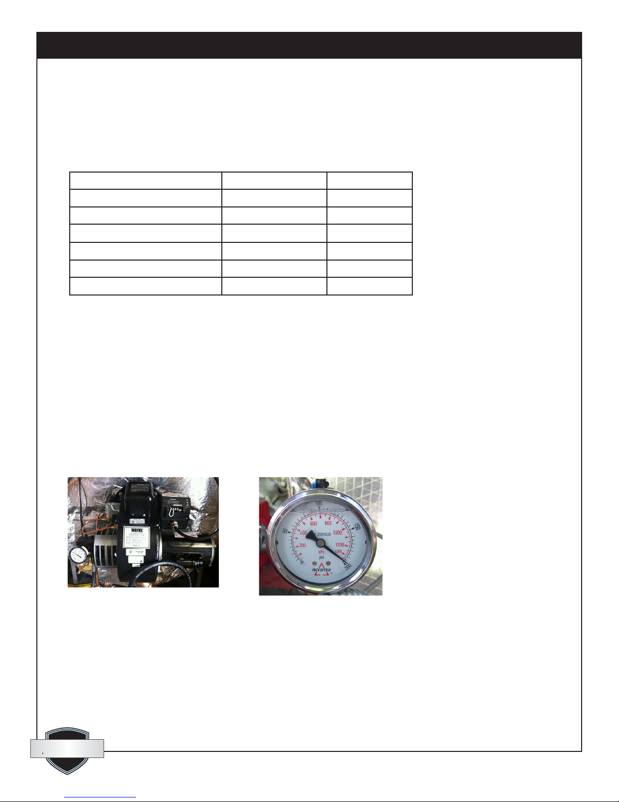
• The “Oil Burner” (Fig. 4) is a pressure-atomization type with direct spark ignition manufactured in the
USA by Wayne Combustion Systems.
• #1 or #2 light heating oil or diesel fuel may be used.
• A gauge is connected to a pressure-tap port on the fuel pump of the burner to aid in setting the burner
and monitoring performance.
• A Fuel Filter is mounted to the burner pump inlet port.
• Supply and return fuel lines are equipped with quick couplers for ease of connection to a fuel tank.
4: CHH-980, Oil Burner 5: Oil Pressure Gauge
quest
quest
1-866-413-5214
www.QuestProtect.com
6
Page 7
Quest Oil Fired CHH-980 Installation, Operation and Maintenance Instructions
CHH-980
Wayne Burner Model
Operational Mode
Electrical Characteristics
Nozzle: Delavan Part #
Fuel Pump Pressure
Fuel Input Rate: factory set
Heat Input: based on 140,000 Btu per USG
Heat Output: @ 80% net efciency
V-A-Hz-Ph 120/11.5/60/1
2 required
PSI (Kpa)
USGPH (Liters/Hr)
Btu/H (Kw/H)
Btu/H (Kw/H)
FH
ON/OFF
2.75-60°B
162 (1117)
7.0 (26.5)
980,000 (287)
784,000 (230)
(Fig. 6)
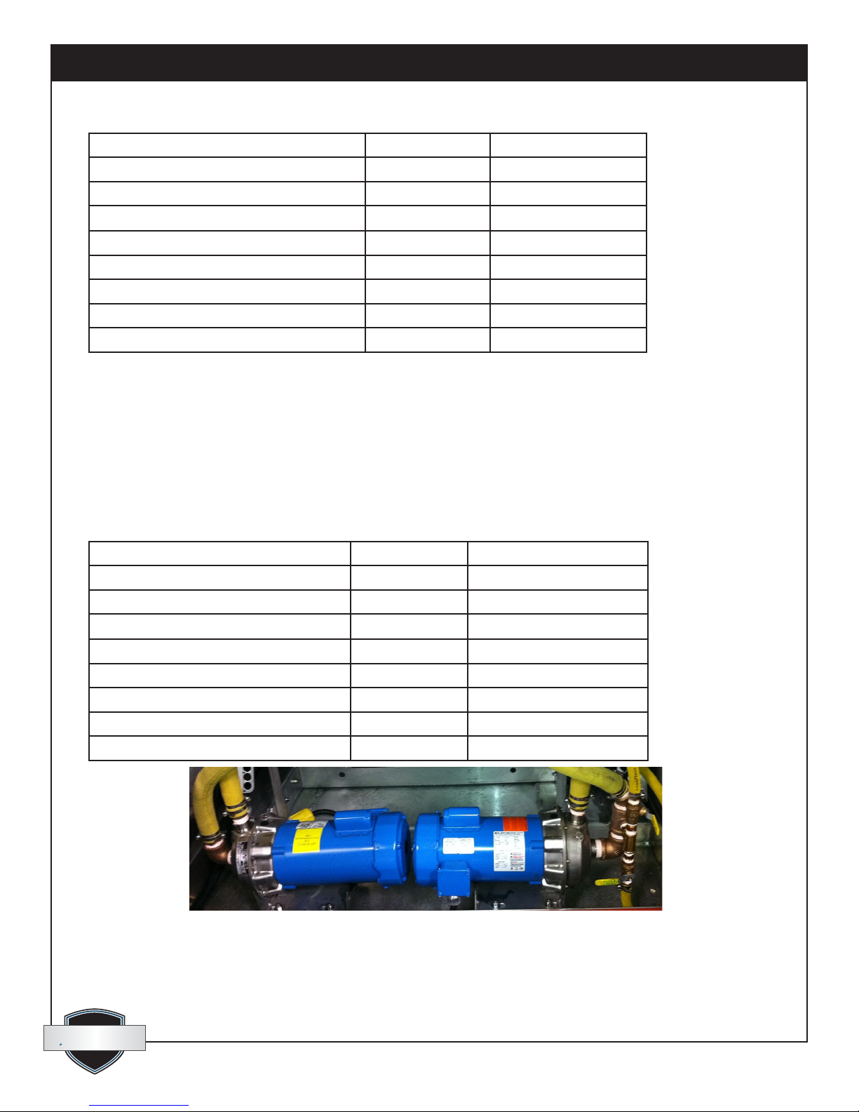
3.4 Circulation Pumps (2 required): (Fig. 8)
• The HTF circulation pumps are stainless steel, direct drive centrifugal type.
• They are located inside the enclosure at the opposite end to the burner and can be accessed through a pair of
hinged lockable doors (Fig. 1).
• A panel-mounted pressure gauge is connected to the output side of the HTF pump manifold by means of a
1/8” ID hydraulic hose and ttings (Fig. 28).
• See chart (Fig. 7) for specications.
2 Pumps required CHH-980
Goulds Pump Model
Impeller Diameter
Motor Horsepower
Voltage Choice
Full Load Amp Rating
System Design Flow Rate, using 1 pump
System Design Flow Rate, using 2 pumps
System Design Operating Pressure
8: Fluid circulation Pumps
1ST1F1B4
inches 5.75
HP 1.5
Volts
Amps
US GPM
US GPM
PSI
120/240
16.6/8.3
35 to 45
35
70
(Fig. 7)
quest
quest
1-866-413-5214
www.QuestProtect.com
7
Page 8
Quest Oil Fired CHH-980 Installation, Operation and Maintenance Instructions
3.5 Electrical Requirements for Complete System
Supply Voltage
Circuit Amperage
Hertz
Phase
Control Circuit Voltage
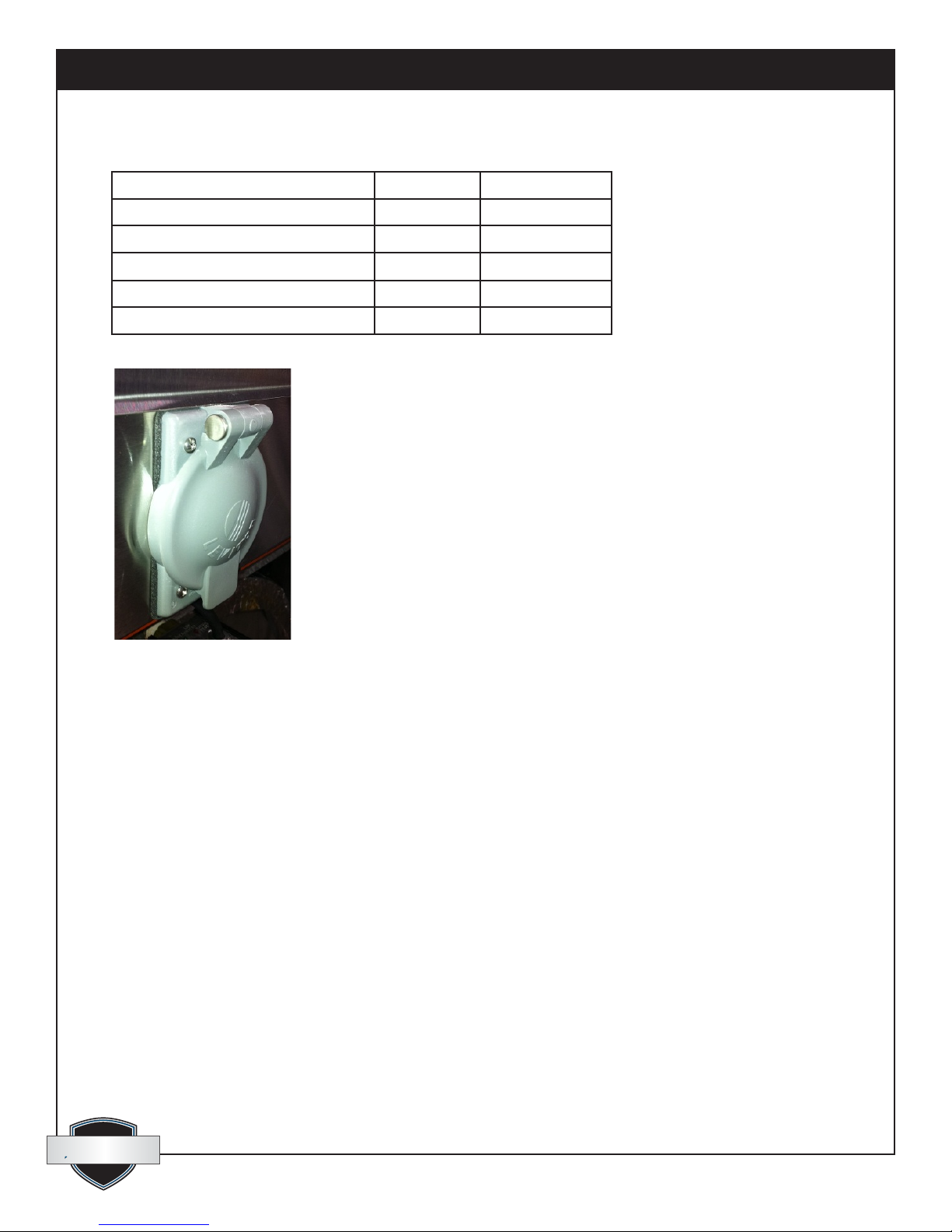
Power Inlet - Male NEMA Twistlock
(Fig. 9)
Volts 120/240
Amps 50
HZ 60
PH single
Volts
120
CS6375M2
10: Power Inlet Plug
3.6 Gauges and Indicator Lights
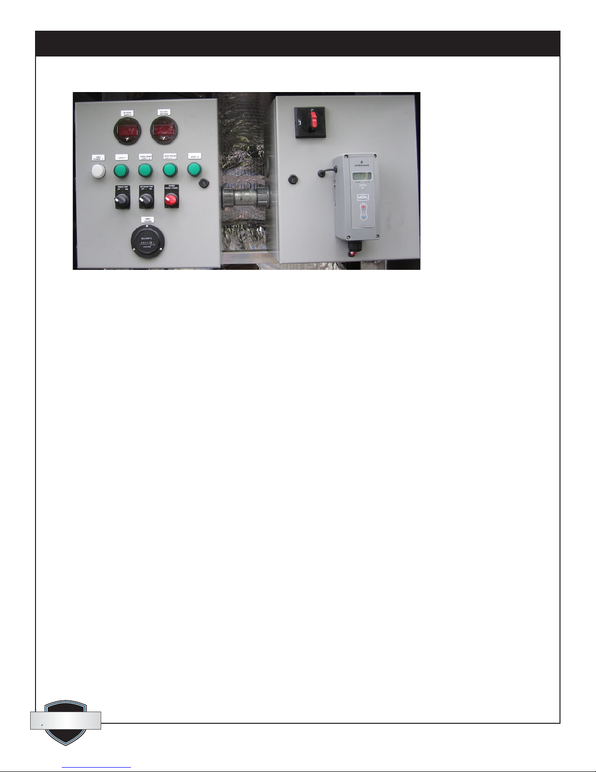
• A group of gauges, controls, switches and status-indicator lights is located on the UL approved control
panel. This panel is located behind the burner access doors near the top (Fig. 2). These gauges and lights are
visible from the exterior through plexi-glass windows in the access doors.
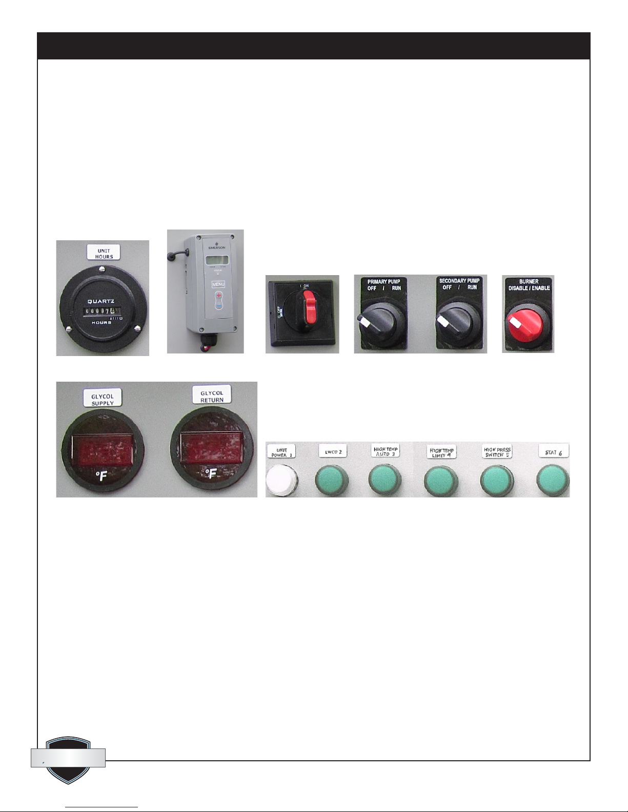
• A digital gauge (Fig. 17) monitors each of the following
- HTF supply temperature.
- HTF return temperature.
• A digital hour meter (Fig. 12) logs system run-time.
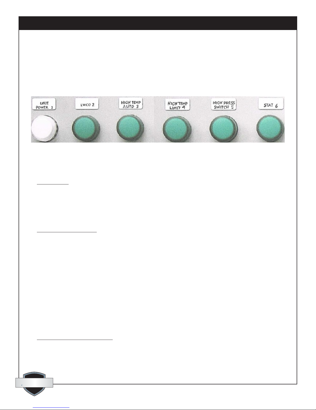
• A series of 6, LED indicator lights (Fig. 18) illuminate in sequence as each of the following scenarios is
proven:
-#1 - 120 volt control power is present - clear lens.
-#2 - HTF level is adequate in reservoir - green lens.
-#3 - High temperature auto control has not interrupted the circuit – green lens.
-#4 - High temperature limit control has not interrupted the circuit – green lens.
-#5 - High pressure limit switch has not interrupted the circuit – green lens.
-#6 - Stat is calling for heat - green lens.
quest
quest
1-866-413-5214
www.QuestProtect.com
8
Page 9
Quest Oil Fired CHH-980 Installation, Operation and Maintenance Instructions
11: Control Panel
3.7 Controls and Electrical
• Specic electrical components are located in and on the UL approved dual-electrical panel, above the
burner. The panel also serves as a junction box for cords going to and from remote electrical components
(Fig. 11).
• The following components are mounted on the front of the UL approved panel:
-Hours meter – 120 Volt (Fig. 12).
-Stat - Electronic operating controller (Fig. 13).
-Main power-disconnect (Fig. 14).
-Pump ON/OFF switches (Fig. 15).
-Burner circuit ON/OFF switch (Fig. 16)
-Glycol supply and return temperature gauges (Fig. 17)
-LED lights – 120 Volt (Fig. 18).
The following components are inside the UL approved panel:
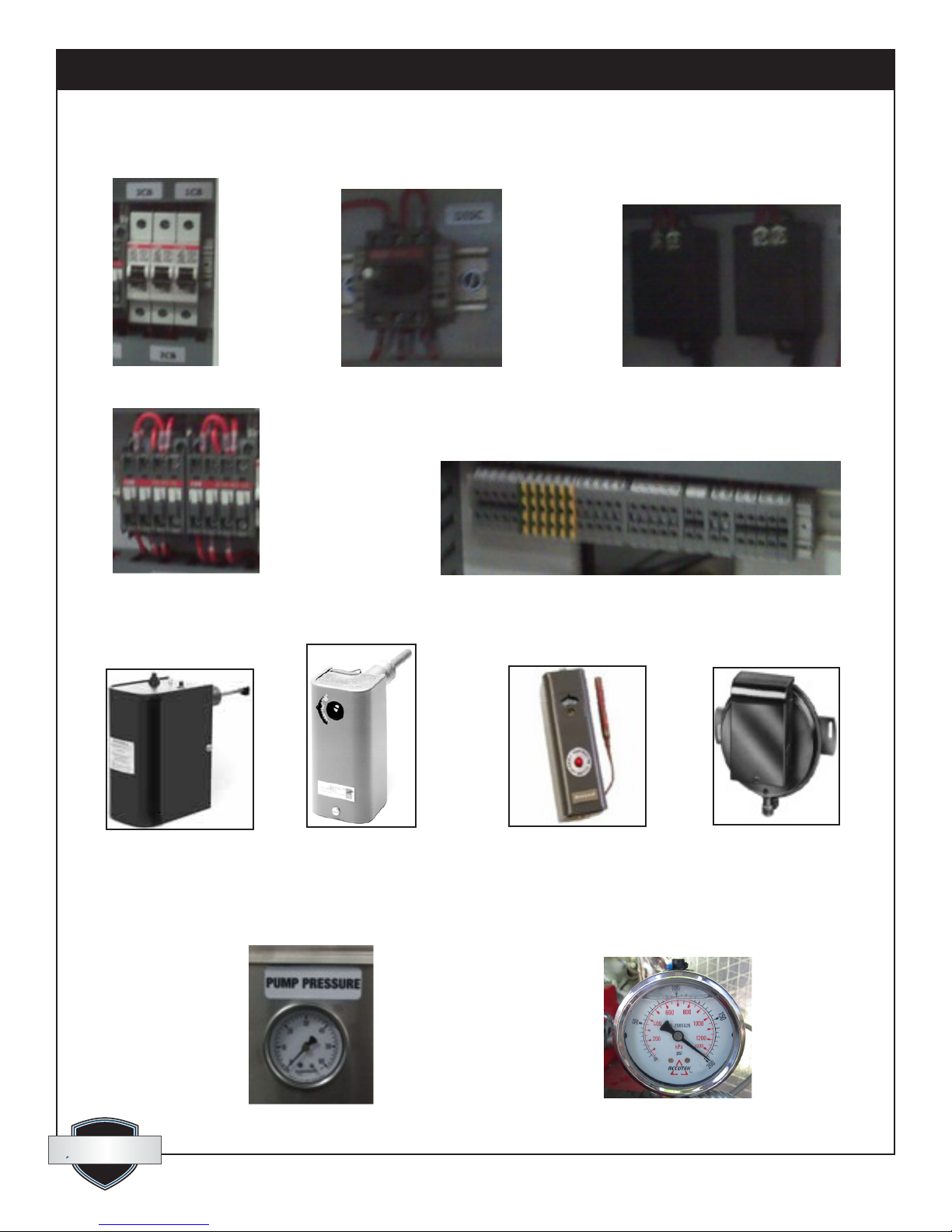
-Main system breaker (Fig. 19).
-Pump circuit breakers (Fig. 19).
-Burner circuit breaker (Fig. 19).
-Main power switch body (Fig. 20).
-Temperature gauge transformers 6VDC (Fig. 21).
-Contactors (Fig. 22).
-Terminal blocks (Fig. 23).
The following items are remotely connected to cords that exit from the control panel:
-Burner (Fig. 4). See burner chart above for details(Fig. 6)
-HTF circulating pump (Fig. 8). See pump chart above for details (Fig. 7).
quest
quest
1-866-413-5214
www.QuestProtect.com
9
Page 10
Quest Oil Fired CHH-980 Installation, Operation and Maintenance Instructions
-Main power male inlet-plug (twist lock) (Fig. 10).
-Low water cut-off switch, (mounted on HTF reservoir) (Fig. 24).
-Automatic reset High limit switch, (mounted in HTF plumbing circuit) (Fig. 25).
-Manual reset High limit switch, (mounted in HTF plumbing circuit) (Fig. 26).
-Manual reset High pressure switch (Fig. 27).
3.8 Controls, Switches & Gauges Identication
• Mounted on Control Panel
12: Hour Meter 13: Stat, Digital 14: Main Power
Switch
17: Glycol Temperature Gauges 18: LED Indicator Lights
15: Pump Switches
16: Burner Switch
quest
quest
1-866-413-5214
10
www.QuestProtect.com
Page 11
Quest Oil Fired CHH-980 Installation, Operation and Maintenance Instructions
• Mounted Inside Control Panel
19: Circuit Breakers 20: Main Power Switch Body 21: Transformers for Digital Temp. Gauges
22: Contactors 23: Terminal Blocks
• Controls Mounted Remotely
24: Low Water Cutoff 25: Auto-reset Temp Limit 26: Man-reset Temp Limit 27: High Pressure Switch
• Pump Pressure and Oil Pressure Gauges
28: Pump Pressure Gauge (PSI) 29: Oil Pressure Gauge (PSI)
quest
quest
1-866-413-5214
11
www.QuestProtect.com
Page 12

Quest Oil Fired CHH-980 Installation, Operation and Maintenance Instructions
4. Setup
4.1 Positioning Equipment on the Job
Before choosing the location to place the central hydronic heater on a job site, several factors should be
considered.
• If possible, the CHH-980 should be placed at a central position that will minimize and equalize the
lengths of hoses. This helps to ensure maximized and equalized HTF ow.
• Convenient access to a suitable electrical connection, if site power is to be used. 120/240V, 1Ph, 60Hz,
50A, 4-wire grounding is required.
• Convenient access for bulk truck re-fueling.
• Do not locate in the path of job site trafc.
• Avoid locations that will expose the CHH to intense dust or other sources of air contamination. Clean
owing air is essential to maintain clean combustion.
• Observe all requirements listed in the “Instructions for Installation” document provided with this unit.
4.2 Hose and Accessory Connections
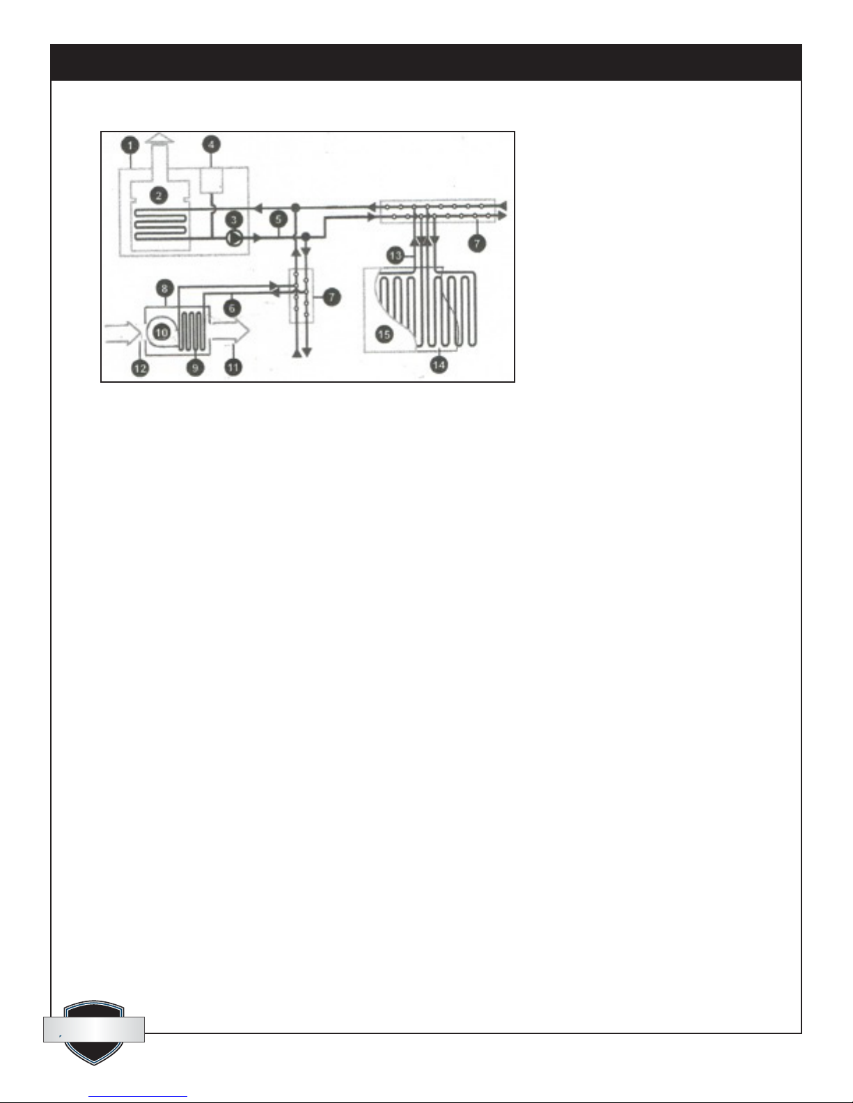
In order to make use of the heated uid, it is necessary to lay out a circuit of hoses to; distribute the hot uid,
transfer its heat to another medium and return the cooled uid to the CHH-980 for re-heating (Fig. 30).
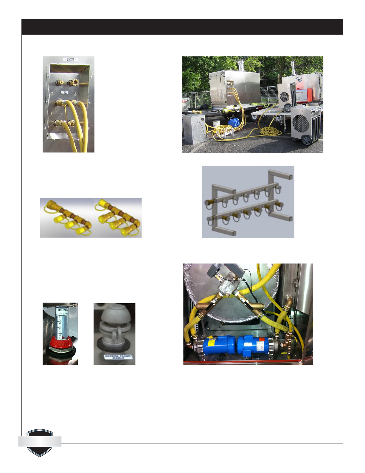
• Up to 3, individual, primary, 1” hose circuits can be connected to the CHH-980 quick-connect
couplings (Fig. 31) to feed the same number of manifolds for either multiple fancoils in air heating
situations (Fig. 33) or multiple 5/8” hose circuits for ground thawing, concrete curing, slab heating or
snow melting (Fig. 34).
• Use only “approved hose” as supplied by ThermaStor. Otherwise, compatibility issues may arise.
• Hoses are pre-charged with the recommended mixture of water and propylene glycol (HTF) and are
equipped with hydraulic-style quick couplers. Every hose has a male connector on one end and a
female connector on the other end; therefore any hose can be used for either the supply side or the
return side of the hose circuit.
• Route hoses to achieve minimum chance of damage from trafc of any kind and at the same time
minimize the overall circuit length.
• Provide protection from “Kinking” of hoses that would restrict ow.
• When connecting quick couplers, ensure that the connections are “Fully Engaged” and snapped into
place or ow will not take place through the coupler connection.
• For long term, building heating projects it is advised to insulate all hose sections located outdoors,
between the CHH-980 and the exterior building wall. This also applies for the primary 1” hose circuits
on a thaw or cure job, to reduce uid heat loss between the CHH-980 and the thaw/cure manifold.
Special “Insulating Wraps” are available for this purpose.
• Connect all primary, 1” hoses from the CHH-980 to the distribution manifold(s). Three manifolds can be
connected at once, each to a separate pair of 1” primary hoses.
• Place all fancoils in the desired locations and route all the secondary hose circuits to them OR lay out
all hose grid circuits for ground thaw or concrete curing.
• Connect hoses between the manifold(s) and the fancoils or the thaw/cure loops.
quest
quest
1-866-413-5214
12
www.QuestProtect.com
Page 13
Quest Oil Fired CHH-980 Installation, Operation and Maintenance Instructions
30: Layout for Fluid Distribution
1. Central Hydronic Heating Unit
2. Burner& Heat Exchanger
3. Circulating Pump
4. Reservoir for Expansion & Filling
5. Primary Fluid Hoses, 1”
6. Secondary Fluid Hoses, 3/4” or 1”
7. Manifold for Multiple Connections
8. Fancoil Heat Exchanger
9. Heat Transfer Coil
10. Air Moving Fan
11. Heated Supply Air
12. Intake Air
13. Hose Grid Line Heat Exchanger 5/8”
14. Vapor Barrier
15. Insulated Tarps
quest
quest
1-866-413-5214
13
www.QuestProtect.com
Page 14
Quest Oil Fired CHH-980 Installation, Operation and Maintenance Instructions
31: Hoses Connected to CHH-980 32: Fancoils Connected to CHH-980 Unit
33: Manifolds for Fancoils - Supply & Return 34: Manifold for Thaw & Cure
35: HTF Level Gauge 37: HTF Circuit Valves, Y-strainers & High Temp. Limits
36: Vented Filler Cap
quest
quest
1-866-413-5214
14
www.QuestProtect.com
Page 15
Quest Oil Fired CHH-980 Installation, Operation and Maintenance Instructions
4.3 Filling the Fluid System
• The CHH-980, all hose and all accessories are shipped pre-charged with the “approved blend” of heat
transfer uid (HTF). The required uid is a 50% blend of Inhibited, propylene glycol and de-mineralized
neutral PH (#7) water. (Freeze protection to -29ºF). The HTF provided with a new system and accessories
is marketed as DowFrost. Use of any other product that cannot be proven to be equal in all respects will
void warranty of the system.
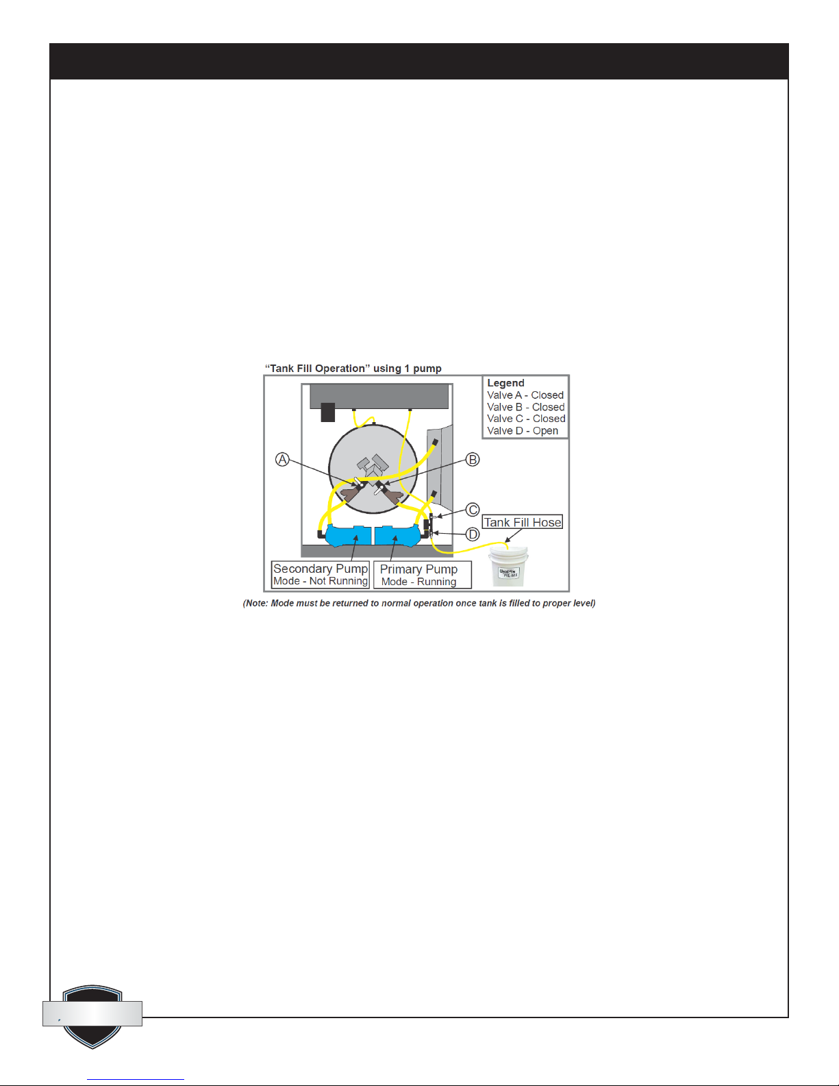
• Check the HTF level gauge (Fig. 35). The reservoir should be ⅛ to ¼ full when the system is cold. Add
approved uid, if necessary, at the vented ller cap (Fig. 36), or use the pumping system to draw HTF
from a pail or barrel. If you prefer this method, place the free open end of the ½” suction hose into a
pail or barrel of HTF and position the valves as shown in (Fig. 38). Turn the “Primary Pump Switch” ON
(Fig. 15). Once the HTF rises to the desired level, turn the pump OFF and set the valve arrangement for
normal operating mode (Fig. 40 or 41 below).
38: Filling Tank from Pail or Barrel.
quest
quest
1-866-413-5214
15
www.QuestProtect.com
Page 16
Quest Oil Fired CHH-980 Installation, Operation and Maintenance Instructions
4.4 Eliminating Air from the HTF Circuit:
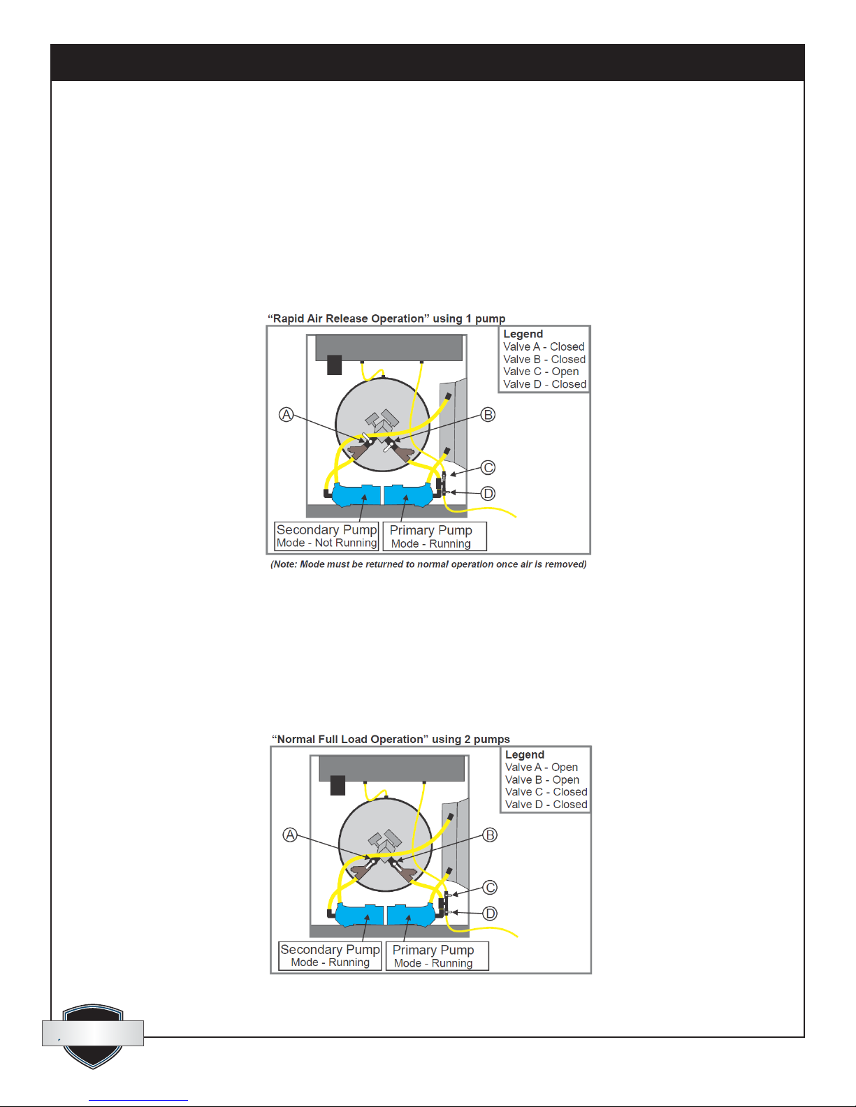
• If there is a signicant amount of air in the HTF circuit, adjust the valves as shown in (Fig. 39). Turn the
“Primary Pump Switch” ON (Fig. 15) and let the uid circulate until all the air is eliminated from system.
Air has been purged when steady pressure of 35 to 40 PSI is observed at the glycol pressure gauge (Fig.
28).
• Once all air is eliminated, turn the pump OFF and set the valve arrangement for normal operating mode
(Fig. 40 or 41 below).
• Check the HTF level again and top up if necessary (1/8 to 1/4 full). See step 4.3 above.
39: Rapid Air Removal.
4.5 Normal 2-Pump Mode with Full Load:
• If the CHH-980 is connected to a distribution system that will demand most of its capacity in terms of
ow requirements and heat draw, the “Normal 2-pump Mode” should be used.
• Adjust the valves as shown in (Fig. 40). Turn ON the “Primary Pump Switch” and the “Secondary Pump
Switch” (Fig. 15).
40: Normal Mode with 2 Pump Operation.
quest
quest
1-866-413-5214
16
www.QuestProtect.com
Page 17
Quest Oil Fired CHH-980 Installation, Operation and Maintenance Instructions
4.6 Normal 1-Pump Mode with Light Load:
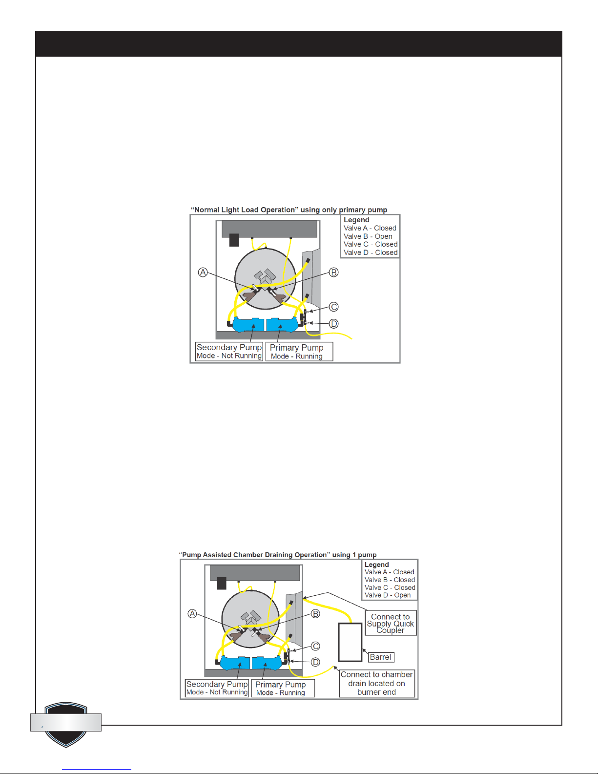
• If the CHH-980 is connected to a distribution system that will demand only half or less of its capacity
in terms of ow requirements and heat draw, the “Normal 1-pump Mode” should be used. This will
provide better efciency for the lighter load.
• Adjust the valves as shown in (Fig. 41). Turn ON only the “Primary Pump Switch” (Fig. 15).
• Keep in mind that either pump could be used in this mode but it is imperative that the valve (A or B) for
the pump not being used must be closed to prevent short circuiting of the uid and greatly reduced outow.
41:Normal Mode with 1 Pump Operation.
4.7 Pump-assisted Chamber Draining:
• If, for any reason, the CHH-980 heat exchanger must be drained, the primary pump can be used to
simplify the draining.
• Locate the 1/2” drainage hose, at the opposite end of the unit, below the burner. Connect this hose to
the short ½” suction hose at valve “D” in (Fig. 42). Garden hose ttings make this connection easy.
OPEN both valves on the 1/2” drainage line below the burner.
• Prepare a short length of 1” hose with a female quick coupler on one end and the other end open.
Connect the female quick coupler to one of the male outlets on the side of the CHH-980. The open end
should be placed in a barrel to catch the uid. It will take more than 100 gallon capacity to hold it all.
• Adjust the valves as shown in (Fig. 42). Turn ON only the “Primary Pump Switch” (Fig. 15).
• When all uid is pumped out, shut OFF the pump switch.
42: Pump-assisted Chamber Drain.
quest
quest
1-866-413-5214
17
www.QuestProtect.com
Page 18
Quest Oil Fired CHH-980 Installation, Operation and Maintenance Instructions
4.8 Oil Burner Installation and Setup: (Fig. 4)
• Refer to the Wayne FH burner Manual (which is included with this package) for detailed information and
instruction.
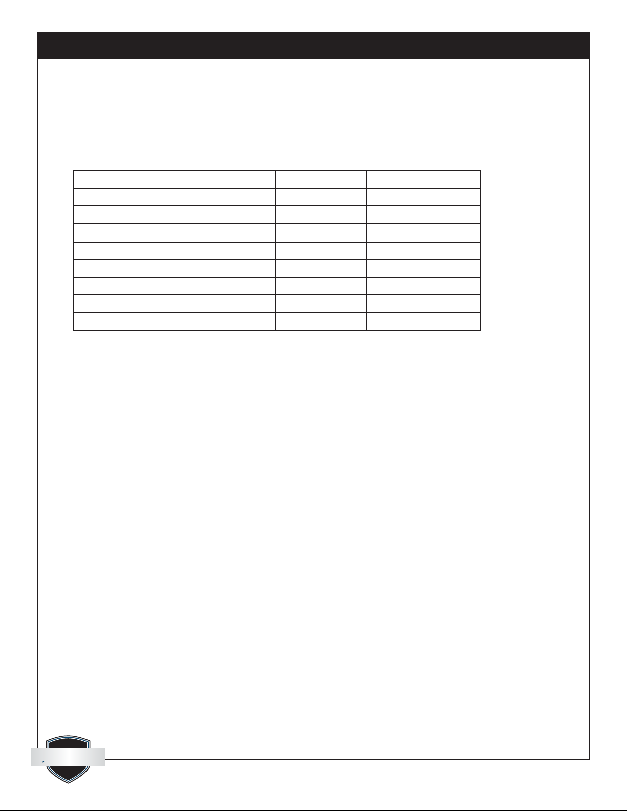
• Specic burner settings for the CHH-980 are as follows.
CHH-980
Wayne Burner Model
Operational Mode
Electrical Characteristics
Nozzle: Delavan Part #
Fuel Pump Pressure
Fuel Input Rate: factory set
Heat Input: based on 140,000 Btu per USG
Heat Output: @ 80% net efciency
V-A-Hz-Ph 120/11.5/60/1
2 required
PSI (Kpa)
USGPH (Liters/Hr)
Btu/H (Kw/H)
Btu/H (Kw/H)
FH
ON/OFF
2.75-60°B
162 (1117)
7.0 (26.5)
980,000 (287)
784,000 (230)
5. Operation
5.1 Startup
• Make sure the CHH-980 is connected to a correct, stable power source (120/240V, 50A, 60Hz, 4-wire
Grounding) and proper gauge chords are used (10 gauge minimum).
• Verify adequate and correct fuel supply (#1 or #2 light heating oil or diesel fuel). Refer to the name/
rating plate. Open all valves in the fuel-supply lines.
• With the main power switch (Fig. 14) in the OFF position, open the control panel door on the right (Fig.
11). Turn ON the three breakers (Fig. 19) and then close the panel.
• Turn ON the main power switch (Fig. 14). The white unit power light (Fig. 18) will come on, as well as
the two digital temperature gauges (Fig. 17) and hour meter (Fig. 12).
• Ensure that the HTF circuit valves are positioned for “Normal Single-pump operation” as in article 4.6
above.
• Turn ON only the primary pump switch (Fig. 15) and check the pump pressure gauge (Fig. 28). Steady
pressure around (35 to 45 PSI), indicates that no air remains in the uid circuit. See article 4.4 above for
rapid air removal.
• Once a stable pump pressure is achieved, turn ON the burner switch (Fig. 16). The following sequence
should now occur: Observe the LED light cluster (Fig. 18).
-The glycol level light will turn on (indicating that there is a sufcient amount of HTF in the system).
-The high temp auto light will turn on. (This indicates that the high auto safety switch has not broken
the circuit).
-The high temp limit light will turn on. (This indicates that the high limit safety switches have not
broken the circuit).
-The high pressure limit switch light will turn on. (This indicates that the blocked ue high pressure
safety switch has not broken the circuit).
quest
quest
1-866-413-5214
18
www.QuestProtect.com
Page 19

Quest Oil Fired CHH-980 Installation, Operation and Maintenance Instructions
-A few seconds later, the stat light will come on and the burner fan will purge the combustion
chamber for a few seconds.
-The burner should light following the pre-purge. If air is still present in the fuel lines or lter, the
burner may not light and lock out. It might be necessary to reset the burner module 2 or 3 times
until fuel reaches the burner head and ignition takes place.
• Make sure the operator (Fig. 13) is set at the desired temperature. DO NOT Operate at temperatures
above 200ºF, or damage to inline controls and certain accessory components can result. To adjust
setpoint on this control just use the up and down key. There is no need to go into the menu of the
control to perform this function. The control simultaneously displays setpoint temperature and actual
supply uid temperature.
• Once the setpoint temperature has been reached, the burner will cycle off and on as needed.
• At this time you can initiate the “2-pump operating mode” if the system is supporting a load of more
than half its capacity. See article 4.5 above for correct HTF valve positions. OPEN valve “A” for the
secondary pump and turn ON the secondary pump switch. Remember that valves “A” or “B” must be
open only when the corresponding pump is running.
5.2 Shutdown
• Turn OFF the burner switch (Fig. 16). The burner will shut down but the circulation pump will continue
to run.
• It is recommended that the uid be allowed to continue circulating until it has cooled down to 100ºF or
lower.
• Turn OFF both pump switches (Fig. 15). If any fancoils and hoses have been placed at a higher elevation
than the CHH-980, the primary hoses should be immediately disconnected from the CHH-980 (Fig. 31).
This will prevent uid from draining back and overowing at the HTF reservoir vent (Fig. 36).
• Turn OFF the main power switch (Fig. 14).
• Turn OFF manual fuel supply valves.
• If the system is to be de-commissioned, it is now safe to disconnect the power supply and all HTF
circulation hoses, manifolds and accessories.
6. Maintenance
6.1 Service Instructions and Checks
“CAUTION: Label all wires prior to disconnection when servicing controls. Wiring Errors
can cause Improper and Dangerous Operation. Verify proper operation after servicing
A. To achieve and ensure clean combustion from the burner, a “ue-gas analyzer” and “smoke spot
tester” must be used to verify clean combustion. Perform the following checks while the burner is ring.
Must be performed by a trained service technician ONLY. Refer to the Wayne model FH manual for burner
adjustment instructions. These checks should be performed, every time, when putting the system into
operation on a new project and a minimum of once yearly.
a. Before starting the burner, determine that the correct nozzles are in place (Delavan 2.75-60ºB). 2
nozzles are required.
quest
quest
1-866-413-5214
19
www.QuestProtect.com
Page 20

Quest Oil Fired CHH-980 Installation, Operation and Maintenance Instructions
b. Fire the burner and ensure that the oil pressure is at 162 PSI. Adjust if necessary.
c. Regulation of combustion air ow is made by adjustment of the manual AIR ADJUSTMENT dial.
Initial suggested setting is (6.0).
d. Final position of the air adjustment plate must be set based on instrument readings of not greater
than 13.0% CO2 and a smoke spot reading of zero. Final readings must be taken with all service-access
doors closed.
B. After placing this unit in operation, the ignition system safety shutoff device must be tested. Must be
performed by a trained service technician ONLY. This check should be performed, every time, when putting
the system into operation on a new project or a minimum of once yearly.
a. Shut OFF the “burner circuit” power switch.
b. Remove the primary control box from the burner and place a small piece of dark tape over the
light-sensing, cad-cell eye that senses the presence of ame in the combustion chamber. Put the primary
control back in place.
c. Turn the power switch back ON and initiate burner lighting procedure. After the short pre-purge
cycle, the burner should light but go out in 5 seconds and lock out. If the burner does not lock out with
the cad-cell eye covered, the primary control should be replaced.
d. To put the unit back in standard operating mode, turn OFF the burner circuit power switch, remove
the tape-cover from the burner’s primary control box, re-insert the control and turn ON the “burner
circuit” power switch.
C. Examine the ue gas exhaust pipe and rain cap to be sure they are solidly attached and free from any
type of obstruction. Clean if necessary.
a. This check should be performed, every time, when putting the system into operation on a new
project or a minimum of once yearly.
D. After placing this unit in operation, the low water safety shutoff device must be tested. Must be
performed by a trained service technician ONLY. The low water cutoff switch is located in plain view at the
same end of the CHH-980 as the circulating pumps and is identied with a label.
a. Push the test switch on the outside of the control. This will simulate a “Low Water” condition and
open the burner circuit to prevent burner initiation.
b. By pushing the reset button, the control will restore function to the burner circuit as long as there is
uid touching the probe. The electronic probe is a “self cleaning” type and should not require service.
c. This control should be tested every time, when putting the system into operation on a new project or
a minimum of once yearly.
E. After placing this unit in operation, the high temperature limit safety shutoff device must be tested. Must
be performed by a trained service technician ONLY. Two high temperature limit switches are located in plain
view at the same end of the CHH-980 as the circulating pumps and are identied with labels. One of these
switches re-sets itself automatically and is set at a slightly lower temperature (about 5ºF) than the other which
must be manually re-set after its set point has been reached.
a. With the burner ring, set the main digital operating stat to a temperature value that is at least 5ºF
higher than the set point of the manual re-set high temperature limit switch.
b. When the uid temperature reaches the set point of the automatic re-set limit switch, it should shut
down the burner. As the uid cools down 2 or 3 degrees, the burner should re-re. This automatic re-set
limit switch should function like a second thermostat and will take over as operator of the burner.
quest
quest
1-866-413-5214
20
www.QuestProtect.com
Page 21

Quest Oil Fired CHH-980 Installation, Operation and Maintenance Instructions
c. If you now adjust the set point of the automatic re-set limit switch to a level a few degrees higher
than the set point of the manual re-set limit switch, the burner should continue to re until the set point
of the manual re-set high limit is reached. At this point the burner should be shut down and this time
should not come back on as the uid cools back down.
d. The manual re-set high limit will need to be manually re-set, by pushing the red re-set button. Adjust
the operator back down to a normal operating lower setting and re-adjust the automatic high limit back
down to its regular set point at about 5ºF lower than the manual re-set limit.
e. These controls should be tested every time, when putting the system into operation on a new project
or a minimum of once yearly.
F. After placing this unit in operation, the high pressure safety shutoff (blocked-ue) device must be tested.
Must be performed by a trained service technician ONLY. The high pressure cutoff switch is located just
below and to the left of the burner and is identied with a label.
a. Remove the chimney rain cap.
b. With the burner ring, cover the chimney ue pipe so it is blocked off completely. This should cause
the pressure switch contacts to open and shut down the burner.
c. Remove the cover from the pipe and replace the rain cap. The burner should not try to re-light since
the switch must be manually re-set.
d. By pushing the reset button (located on the electrical box cover of the pressure switch), the control
will reset and the burner should light again.
e. This control should be tested every time, when putting the system into operation on a new project or
a minimum of once yearly.
G. Procedure for cleaning ue gas passageways. This procedure should be performed in the event of
blockage in the ue fuel passage due to soot or any other obstruction that may occur. Improper burner
settings or maintenance could cause soot accumulation in the combustion chamber. The following steps
should be taken to clean out the chamber ue gas passageway. Must be performed by a trained service
technician ONLY.
a. Shut off fuel supply and electrical power supply.
b. Drain the heat transfer uid from the system.
c. The control panel should be loosened from its mounting frame.
d. Once access to the chamber has been gained, disconnect the burner electrical supply line and
fuel supply lines and remove the burner. 4 bolts will need to be removed that hold the burner to its
mounting ange.
e. Disconnect the ue exhaust vent pipe by removing screws. Remove the pipe and rain cap assembly
and clean its interior thoroughly.
f. Hoses will need to be disconnected by loosening the hose clamps and pulling the hose off the insert
barbs.
g. Remove all bolts that hold the chamber ange plate disk to the main chamber body.
h. The inner section of the combustion chamber can now be pulled straight out of the main chamber
body. A fork lift or other machinery may be required for this procedure since the chamber is very heavy.
i. All ue exhaust gas contact surfaces are now exposed and can be easily cleaned with vacuum
cleaner, brushes or other cleaning utensils.
quest
quest
1-866-413-5214
21
www.QuestProtect.com
Page 22

Quest Oil Fired CHH-980 Installation, Operation and Maintenance Instructions
j. To re-assemble the unit, replace components in reverse order to which they were removed.
k. Reconnect fuel and power supply to the unit and when re-starting the system perform all safety and
service checks as outlined above.
H. The CHH-980 will produce condensate while operating, at any time that the circulating uid is cooler
than approximately 130ºF (54ºC). A 1/2” hose is connected to a tting in the bottom of the chamber at front
and is routed to the outside of the cabinet to carry condensate away. This tube should be inspected and
cleaned, if necessary, when putting the system into operation on every new project or a minimum of once
yearly.
I. Flame inspection is recommended on a frequent basis (about once per month under normal continuous
service) and a ame inspection port is available for this. It is located behind a ip-up door at the top of the
burner. Must be performed by a trained service technician ONLY.
a. Normal ame should be bright orange-yellow.
b. Although visual inspection is benecial. We strongly recommend that instruments be used to check
combustion quality. This procedure is outlined in (#.1), above.
J. On a daily basis, the area around this system must continue to be kept clear and free from combustible
materials, gasoline and all other ammable vapors and liquids.
K. At both ends of the CHH-980 cabinet, Louvers are stamped into the access doors to provide intake air
for combustion and ventilation. Check on a daily basis to ensure that nothing is allowed to obstruct this free-
ow of air.
L. Check heat transfer uid level daily. Maintain between 1/4 cold and 1/2 hot during normal operation. If
excessive uid loss occurs check all hoses and connections for leaks. Top-up only with approved HTF. (See
User’s Manual for details).
M. Verify that all gauges are maintaining within their desired operating ranges with respect to setpoint.
N. Check fuel tank level daily and order fuel as required.
O. Make sure that all access doors and panels are kept closed and locked while the system is in use.
P. Isolate and clean both Y-strainers before each set up, at least once per year or as required due to uid
contamination. To clean the Y-strainers (Fig. 37) close the ball valves “A” and “B”, immediately above the
Y-strainers and disconnect all the quick-coupler connections at the alcove manifold (Fig. 31), on the outside
of the cabinet. This will isolate the Y-strainers. The caps on the Y-branches can now be removed so the
cylindrical screens can also be removed. Clean the screens with compressed air or a small wire brush. Put
the screens back in place and re-engage the caps, quick coupler connections and valves.
For further service assistance
Call the manufacturer toll free at: 866-413-5214 to speak to a Hydronic Service Specialist.
quest
quest
1-866-413-5214
22
www.QuestProtect.com
Page 23
Quest Oil Fired CHH-980 Installation, Operation and Maintenance Instructions
MAINTAINENCE TASKS
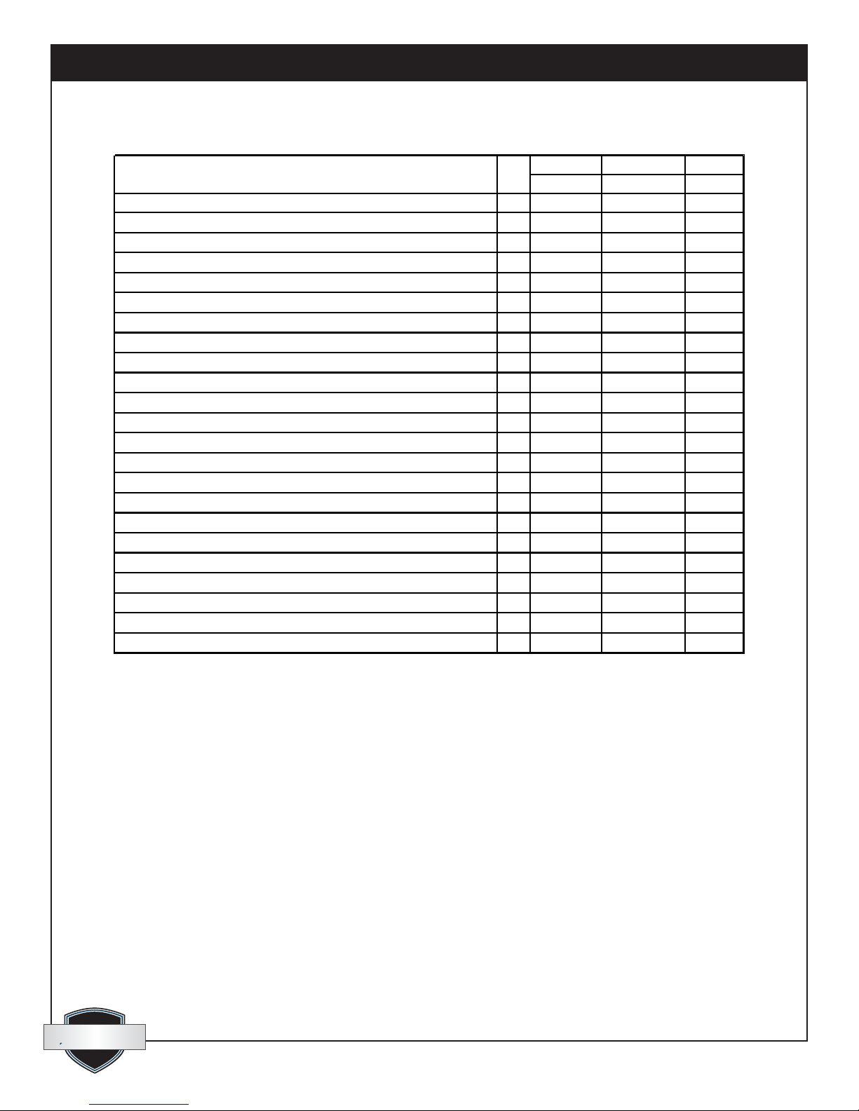
6.2 Maintenance Frequency Chart
Start of Every Start of Heating As
Daily
User Performed Tasks:
Check pressure & temperature gauges for "Normal Function Lev els" during operation
Check Aquastat for "Correct Setpoint" during operation
Check LED lights for "Correct Function" during operation
Check Fuel Gauge and order a delivery if necessary ( Propane sy stems only )
Check HTF Lev el Gauge and add HTF if necessary
If HTF loss is excessive, Check all Hoses & accessories for Leaks and Repair
Clean Y-strainer's Screens
Ex amine all hoses and replace or repair any that are cracked or in any w ay damaged
Lubricate all quick couplers w ith light oil
Thoroughly Clean the sy stem inside and out
Ex amine The Flue gas ex haust pipe and Rain cap. Clean as needed
Check condensate drainage tube and clean if necessary
Make c ertain that no flammable materials are any w here near the heating unit
Make c ertain that nothing is allowed to obstruct the combustion air intake louvers
Project Season Necessary
√ √ √
√ √ √
√ √ √
√ √ √
√ √ √ √
√
√ √ √
√ √ √
√ √
√ √
√ √ √
√ √ √
√ √ √ √
√ √ √ √
To be Performed by Trained Service Technician
Perform a Flue Gas Analy sis test (using instruments) to confirm clean combustion
Test Ignition Safety Shutoff device on burner
Test Low Water Cut-off Safety sw itch
Test High Temperature Limit sw itches
Test High Pressure Limit (blocked flue) sw itch
Check flue gas passagew ay s for soot or any ty pe of blockage and clean if necess ary
√ √ √
√ √ √
√ √ √
√ √ √
√ √ √
√ √
quest
quest
1-866-413-5214
23
www.QuestProtect.com
Page 24
Quest Oil Fired CHH-980 Installation, Operation and Maintenance Instructions
7. Troubleshooting
7.1 Fault Determination
The CHH-980 is equipped with a group of LED “Indicator Lights”. The purpose of these lights is to aid in
determining where the fault lies if the heating unit should fail to function properly. The following sequence
explains the function each light represents and what to look for if that function should fail:
IMPORTANT: If all switches have been turned ON and the system was operating
correctly, but has now FAILED, the status of these 6 lights will help to isolate the
problem.
All Lights OFF indicates.
A. NO power through the main power switch. Check the following:
a. Is main power switch (Fig.14) still turned on?
b. Are the circuit breakers (Fig. 19) still turned on?
c. Verify external power supply (120/240V) to inlet plug (Fig. 10).
#1 Unit Power Light is ON indicates.
A. Power is present through main switch. The 2 digital temperature gauges should be ON. If not, use a
multi-meter to check the following:
a. The 2 transformers (Fig. 21) should show 120VAC in and 6VDC out. If power goes in but not out,
replace transformer.
b. If there is 6VDC at the digital gauge but it does not illuminate, replace the temp. gauge.
B. There is no power going through the low water cutoff (LWCO) switch (Fig. 24).
a. Check uid level in reservoir. Should be at least 1/4 level. Add if necessary.
b. Check, with a multi-meter, for 120V in and out of LWCO switch. If uid is adequate and there is
power in but not out, replace the LWCO switch.
c. With no power going to the burner limit circuit and the burner panel switch turned ON, the alarm
circuit of the LWCO should be energized (120V). This opens contacts in a relay that will prevent the
pumps from running with no uid in the system.
#2 LWCO Light, (plus #1) are ON indicates.
A. LWCO switch (Fig. 24) is sensing sufcient glycol in the reservoir and power is going through the switch.
B. There is no power going through the high temperature limit switches (Fig. 25).
quest
quest
1-866-413-5214
24
www.QuestProtect.com
Page 25
Quest Oil Fired CHH-980 Installation, Operation and Maintenance Instructions
a. Check the set points on the high temperature auto switch (Fig. 25) and digital stat (Fig. 13). If the
set point of the stat is equal to or higher than the set point of the high temperature auto switch (Fig. 25),
the high temperature auto switch will be functioning like a stat and cycling the burner off and on. Light
#3 will be cycling in-step with the burner. The digital stat should always be set (maximum 200ºF), a few
degrees lower than the high temperature auto switch (about 210ºF).
b. With the actual uid temperature well below the set point of the high temperature auto switch,
check, with a multi-meter, for 120V in and out of the high temperature auto switch (Fig. 25). If there is
power in but not out, replace the high temperature auto switch.
#3 High Temp. Limit Light, (plus #1 & #2) are ON indicates.
A. Fluid supply temperature is below the set-point of the high temperature auto switch (Fig. 25) and power
is going through the switch.
B. There is no power going through the high temperature Limit switch (Fig. 26).
a. Check the set points on the high temperature Limit switch (Fig. 26), the high temperature auto switch
(Fig. 25) and digital stat (Fig. 13). If the set points of both the high temperature auto switch and the stat
are equal to or higher than the set point of the high temperature limit switch (Fig. 26), the high temp
limit switch will be locked out and the burner off. Light #3 will be off. It will be necessary to push the
manual reset button on the front of the high temp limit switch and check the set points of all 3: The high
temp auto switch (210ºF), the high temp limit switch (220ºF) and the digital stat (maximum 200ºF).
b. With the high temp limit switch re-set and actual uid temperature well below the set points of both
high temp switches, check, with a multi-meter, for 120V in and out of the high temp limit switch (Fig.
26). If there is power in but not out, replace the high temp limit switch.
#4 High Pressure Switch Light, (plus #1, #2 & #3) are ON indicates.
A. Fluid supply temperature is below the set-point of the high temp limit switch (Fig. 26) and power is
going through the switch.
B. There is no power going through the NC contacts of the high pressure switch (Fig. 27).
a. Check the set-point of the high pressure switch. Start by turning the adjuster screw all the way
counter-clockwise. Then turn the screw clockwise 3 full turns. Push the manual reset button on the
pressure switch to restore the circuit.
b. Check the air tube connection to the pressure switch and clean if necessary. Push the manual reset
button on the pressure switch and the circuit should be restored. If not check for 120 volts going in and
out of the control. If power goes in but not out, replace the control.
c. If the circuit is restored briey but it trips again, blockage may have occurred in the ue gas
passage way. Clean the ue gas passages in the combustion chamber (see Maintenance article 6.1 G for
instructions) as well as the chimney pipe and rain cap. Repeat step a) above.
#5 High Pressure Switch Light, (plus #1, #2, #3 & #4) are ON indicates.
A. Pressure in the combustion chamber and ue pipe has not risen above the high limit cutoff point. Power
is going through the NC contacts of the high pressure switch (Fig. 27). Indicates no blockage in any of
the ue gas passages.
B. There is no power going through the digital stat switch contacts (Fig. 13).
#6 Stat Light, (plus #1, #2, #3, #4 & #5) are ON indicates.
A. The digital stat (Fig. 13) is calling for heat. The burner should be engaged.
B. If the burner is not functioning, a fault lies within the burner.
quest
quest
1-866-413-5214
25
www.QuestProtect.com
Page 26

Quest Oil Fired CHH-980 Installation, Operation and Maintenance Instructions
7.2 Burner Internal Faults
Diesel/Light Oil Burner
Below is a list of scenarios and possible causes for burner failure.
A. The burner goes through the prepurge period normally. The ame ignites, but the burner goes to lockout
within ve seconds.
a. The phase/neutral lines are reversed. Correct polarity is critical.
b. The wiring to ground is absent or ineffective.
c. The electric eye, light-sensing switch is dirty or defective. Try cleaning they eye. If it still fails,
replace it.
B. The burner goes to lockout after the prepurge period because the ame does not ignite.
a. No fuel in tank or lines.
b. Air has not been fully bled from the fuel lines.
c. Check fuel lines. The smallest leak will allow air to enter and prevent ignition.
d. The fuel lter is dirty. Replace lter.
e. Nozzle is plugged. Replace nozzle.
f. The spark is irregular or not present. Re-align electrodes. Check ignition transformer (replace if
defective).
C. The burner does not start when the thermostat calls for heat.
a. Loose wire connection at terminals L or N.
b. Terminals on the control module are bent or loose
c. The motor is defective.
d. The capacitor is defective.
e. The control box is defective.
D. For additional information refer to the Wayne model FH manual, included in your data package.
quest
quest
1-866-413-5214
26
www.QuestProtect.com
Page 27
Quest Oil Fired CHH-980 Installation, Operation and Maintenance Instructions
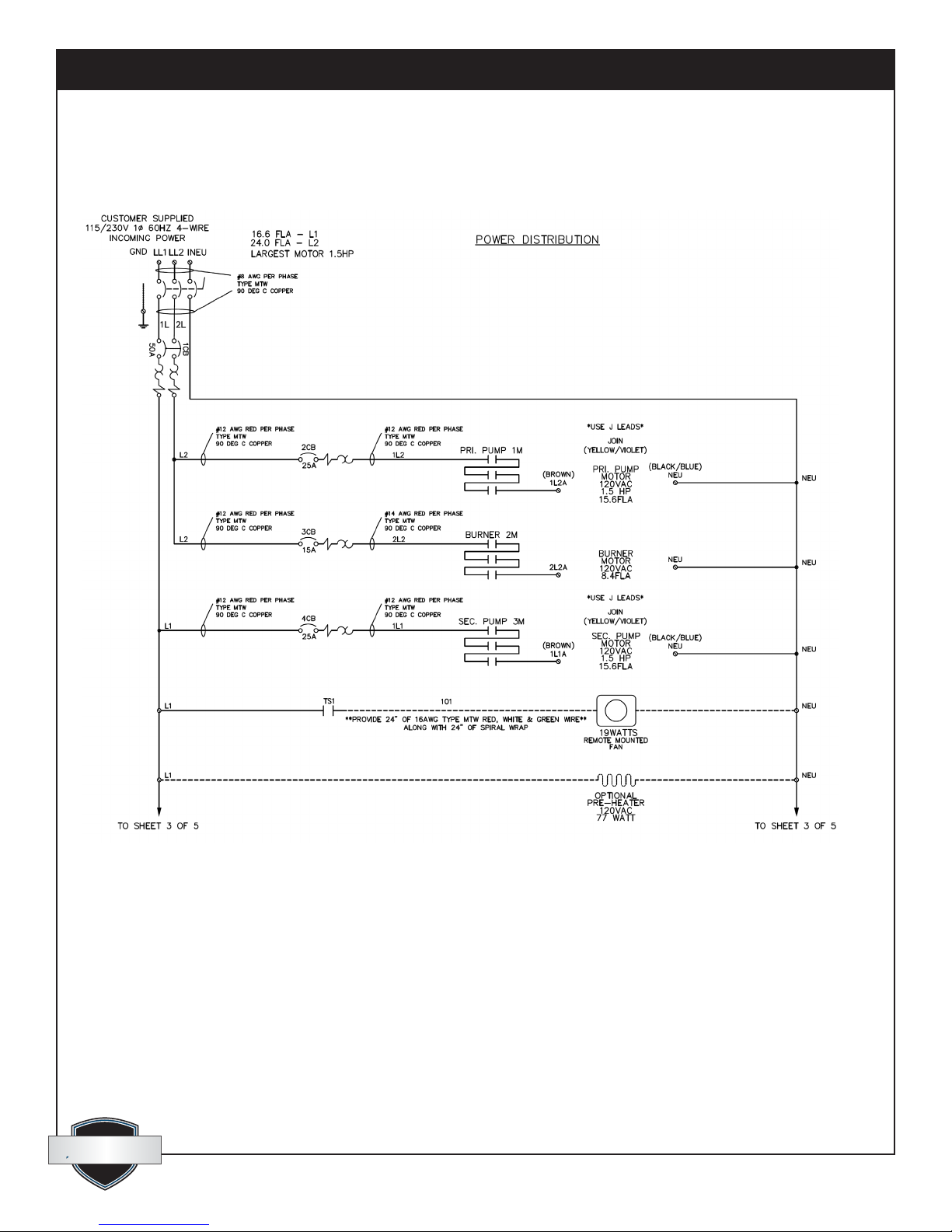
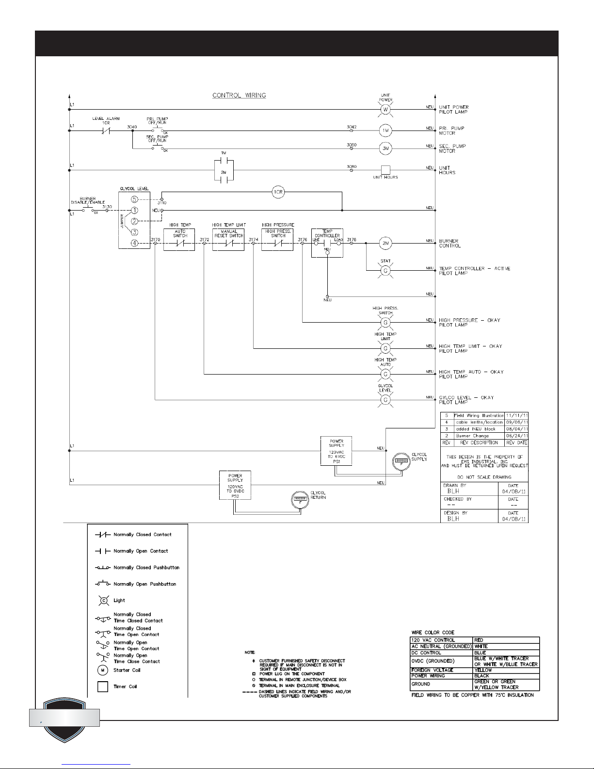
7.3 Electrical Schematics
quest
quest
1-866-413-5214
27
www.QuestProtect.com
Page 28
Quest Oil Fired CHH-980 Installation, Operation and Maintenance Instructions
quest
quest
1-866-413-5214
28
www.QuestProtect.com
Page 29
Quest Oil Fired CHH-980 Installation, Operation and Maintenance Instructions
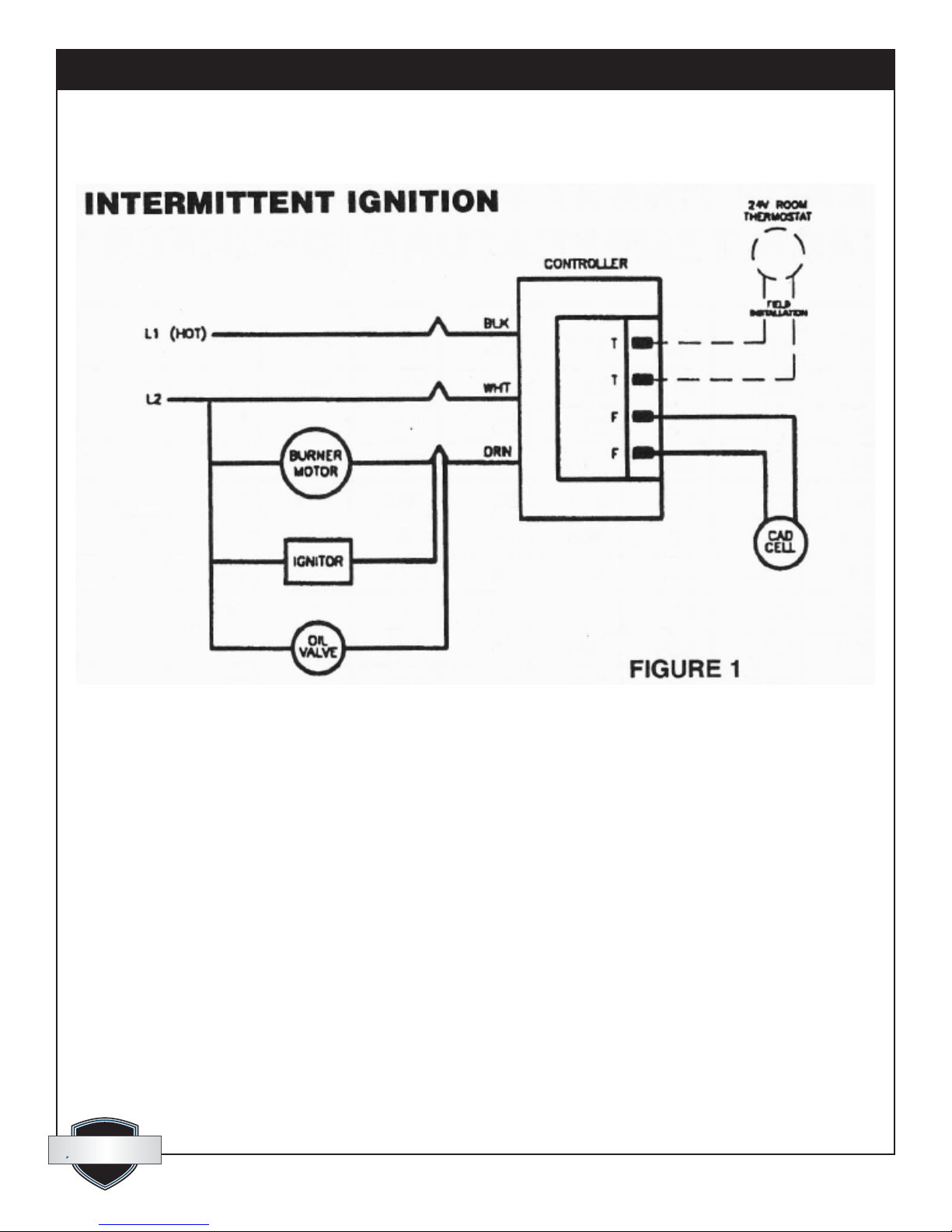
Wayne FH Burner
quest
quest
1-866-413-5214
29
www.QuestProtect.com
Page 30

Quest Oil Fired CHH-980 Installation, Operation and Maintenance Instructions
Quest CHH-980 Limited Warranty
Warrantor:
Therma-Stor LLC
4201 Lien Rd.
Madison, WI 53704
Telephone: 1-866-413-5214
Who Is Covered: This warranty extends only to the original end-user of the Quest CHH-980 and may
not be assigned or transferred.
One Year Warranty: Therma-Stor LLC warrants that, for one (1) year the Quest CHH-980 will operate
free from any defects in materials and workmanship, or Therma-Stor LLC will, at its option, repair or
replace the defective part(s), free of any charge.
End-User Responsibilities: Warranty service must be performed by a Servicer authorized by ThermaStor LLC. If the end-user is unable to locate or obtain warranty service from an authorized Servicer,
the end-user should call Therma-Stor LLC at the above number and ask for the Therma-Stor Service
Department., which will then arrange for covered warranty service. Warranty service will be performed
during normal working hours.
The end-user must present proof of purchase (lease) upon request, by use of the warranty card or
other reasonable and reliable means. The end-user is responsible for normal care. This warranty does
not cover any defect, malfunction, etc. resulting from misuse, abuse, lack of normal care, corrosion,
freezing, tampering, modication, unauthorized or improper repair or installation, accident, acts of
nature or any other cause beyond Therma-Stor LLC’ reasonable control.
Limitations and Exclusions: If any Quest CHH-980 part is repaired or replaced, the new part shall be
warranted for only the remainder of the original warranty period applicable thereto (but all warranty
periods will be extended by the period of time, if any, that the Quest CHH-980 is out of service while
awaiting covered warranty service).
UPON THE EXPIRATION OF THE WRITTEN WARRANTY APPLICABLE TO THE QUEST CHH980 OR ANY PART THEREOF, ALL OTHER WARRANTIES IMPLIED BY LAW, INCLUDING
MERCHANTABILITY AND FITNESS FOR A PARTICULAR PURPOSE, SHALL ALSO EXPIRE. ALL
WARRANTIES MADE BY THERMA-STOR LLC ARE SET FORTH HEREIN, AND NO CLAIM MAY
BE MADE AGAINST THERMA-STOR LLC BASED ON ANY ORAL WARRANTY. IN NO EVENT
SHALL THERMA-STOR LLC, IN CONNECTION WITH THE SALE, INSTALLATION, USE, REPAIR OR
REPLACEMENT OF ANY QUEST CHH-980 OR PART THEREOF BE LIABLE UNDER ANY LEGAL
THEORY FOR ANY SPECIAL, INDIRECT OR CONSEQUENTIAL DAMAGES INCLUDING WITHOUT
LIMITATION WATER DAMAGE (THE END-USER SHOULD TAKE PRECAUTIONS AGAINST SAME),
LOST PROFITS, DELAY, OR LOSS OF USE OR DAMAGE TO ANY REAL OR PERSONAL PROPERTY.
Some states do not allow limitations on how long an implied warranty lasts, and some do not allow
the exclusion or limitation of incidental or consequential damages, so one or both of these limitation
may not apply to you.
Legal Rights: This warranty gives you specic legal rights, and you may also have other rights which
vary from state to state.
quest
quest
1-866-413-5214
30
www.QuestProtect.com
 Loading...