

Page 1
SB10
SB10
User Manual
Quested Mon itorin g Sy st ems Ltd.,
Un it s 6 -8 King sg ate,
Heathpark Ind ustrial Estate,
HO NITON,
Dev on EX14 1Y G
En gland
Tel: ++(0)140 4.4 15 00 Fax: ++(0)1404 .44 660
ww w.q uested.com
Page 2

2
CONTENTS
1 Introduction 3
2 Safety Considerations 3
2.1 General 3
2.2 Hearing damage 4
3 Unpacking 4
4 Installation 4
4.1 Positioning 4
4.2 Stand Mounting 5
4.3 Electrical Connection 5
4.3.1 Safety Earthing
4.3.2 Voltage Setting
4.3.3 Fuse Set ting 6
4.4 Audio Con nections 6-8
5 Operational Considerations 8
5.1 Mains On-Off Switching 8
5.2 Front panel indicators/con trol 8
5.3 Test 8
5.4 Crossover frequency 8
5.5 Bypass 8
5.6 Gain 8
5.7 Phase 8
5.8 Polarit y 8
5.9 Power 9
5.10 Rear Panel Controls 9
Left input filter bypass
5.11 Internal Settings 9
Sub sonic/High pass fil ter
6 Setting up: The Wh ys and Hows of subwoofer use 9-13
6.1 WHY?
6.2 HOW?
7 Tech nical Specification 13-14
8 Line Drawing 14
9 Guarantee 14
10 Appendix 15
10.1 Accessories
10.2 Spares
1 0.3 Driver replacement
1 INTRODUCTION
Page 3

3
Thank you for purchasing this Quested mo nitor. You can be cer tain that y ou have purchased one
of the finest monitors in the world. If you take ti me and care in positio ning and aligning t he sys tem,
you will appreciate why Quested monitors have a reputation for faithful reproduction covering the
entire audible spectrum. They are professional monitors and therefore are no t designed to flat ter
but to faithfully reproduce. Please take care to maintain the system and it will give you many years
of service. You will also be assured the best p ossible performance and long-term reliabilit y of your
system.
Please read this manual, which we have kept as co ncise as possible, as it really will help you and
covers important safety considerations.
The SB 10 is a remote-p owered sub woofer. Its remote elect ronics and its co mpac t size make it
ideal in areas where space is at a premium but bass extensio n is still a requiremen t. However its
power output of 210 Wa t ts RMS also enables the sub bass to be used in larger rooms and
applications requiring a p owerful yet portable monitor. The SB10 has variable low and high pass
filters, which allow it to be matched accurately with a variety of full range cabinets. Used in
conjunction with th e Quested S6, S7 or S8 active 2-way monitors, the SB10 enables an active, 3way, full range system in rooms that would preclude the use of a large full range monitors
The SB 10 is remo te powered, i.e. the amplifier and crossover electronics are housed in a separate
1U box. This brings with it several advantages. Firs tly y ou can now mount the S B 10 electronics
close to hand, bringing monito ring functions and met ering to hand. This also makes it a lo t easier
to precisely setup the sub bass. Additionally very low frequency reproduction causes vibration. In
standard self-p owered designs these vibrations often feed back th rough the microph onic
componen ts within the amplifier and cause distortion. Another advantage of this design is that the
cabinet and electronics can be upgraded independently of each other. Typical applications include
near to mid-field bass extension or dedicated LFE channel for recording/mixing, programming, p ost
production suites, broadcast and surround sound.
2 SAFETY CON SIDERATIONS
2.1 Genera l
Before proceeding to connect y our Quested monitor to the AC power supply , please read the
following safety informa tion:-
CAUTION: RISK OF ELECTRICAL SH OCK. REFER SERVICING TO QUALIFIED
PERSONNEL.
THE POWER C ORD MUST ALWAYS BE REMO VED BEFORE THE
AMPLIFIER IS
DISMANTLED.
WARNING: TO REDUCE THE RISK OF FIRE OR ELECTRICAL SH O CK, DO NOT
EXPOSE THIS
APPLIANCE TO RAIN OR M OISTURE.
WARNING: THIS APPLIANCE MUST BE EARTHED.
The cores in the supplied mains lead are colour coded in accordance with the following code:
Green and Yellow: Earth
Blue: Neutral
Brown: Live
As th e colours of these wires may not correspond with the coloured markings identifying the
terminals in your plug, proceed as follows:
T he wire, which is coloured green and yellow, must be connected to the terminal in the plug,
which is marked with the lett er ‘E’ or by the earth symbol, or coloured green and yellow.
The wire, which is coloured blue, must be connected t o t he terminal in the plug which is marked
with the letter ‘N’ or coloured black.
Page 4

4
The wire, which is coloured brown, must be co nnected to the terminal in the plug which is marked
with the letter ‘L’ or coloured red.
NOTE: For certain countries the power cord will be supplied with an int egral moulded plug
to satisfy natio nal safety standards.
CAUTION: THIS UNIT C O NTAINS MAGNETIC C OMPONENTS, WHI CH CAN AFFECT
ADJACENT
SENSITIVE EQUIPMENT.
2.2 Heari ng damag e
This equipment can deliver sound pressure levels in excess of 100 dB. At this level permanent
hearing damage can occur and ex posure to this level of sound, even for relatively short periods
(see table below), can be harmful. Of equal importance to the maximum level of sound is the
exposure t o high levels of sound for extended periods. There are no in ternationally agreed limits
and different countries have differen t limits, which are measured in differing ways. IT IS
IMPOR TAN T THEREFORE THA T TH E USER ESTABLISHES THE RECOMMENDED, AND
IN SOME
TERRI TORIES, LEGAL LIMITS WHICH ARE IN PLACE. As a guide the table below shows the
levels
that are acceptable in the majority of Western Europe, the US and Canada:
dB(A) Lis t e n i n g t ime per day
90 8 hours
95 2.4 hours
100 40 minu tes
105 15 minu tes
110 5 minutes
115 and over Not at all
It is also importan t to n ote that the effect of exp osure to sound is cumulative. Having listened to
sound for example fo r 15 minutes at 1 05 dB, further ex posure to noise levels above 80 dB should be
avoided until th e next day.
3 UNPACKING
T his Quested product has been carefully manufactured, tested and packed to ensure that it arrives
in a flawless condition. The component parts of the packing have been thoughtfully designed to
offer sufficient p rotec tion during transportation, yet remain fully recyclable and should be retained
for future use. Also included in a separate bag will be t he appropriate power cord for your country.
4 INSTALLATION
4.1 Posit io ning/Moun ting
T he SB10 is designed to be mounted either ver tically or horizontally. It should be placed on the
floo r close to the cabinets it is reinforcing. If a single cabinet is used in mono, it should ideally be
placed as described in the detailed setting up instructions on page 9 of this manual. If two cabinets
are to be used they should be placed directly under t he stereo, full range boxes. T here is a linking
stand available for t his purpose. Where p ossible avoid positioning the S B10 in a corner as this
increases t he chance of exciting standing waves within the room, creating an unpleasant
boominess. It is imp ortant th at if placed on a floor, t he floor is flat and if mounted, the ch osen
support is rigid so that the speaker does n ot vibrate when the monitor is driven. The supplied
spikes or feet should be used to stabilize t he cabinet. Vibratio ns caused from uneven placement
will result in lack of low frequency definition. Its positioning close to or away from the rear wall
and
proximity to any roo m corners is best determined by experimenting and placing the speaker in
differing positions. T he shape o f the room, n ormal listening position and roo m treatment will all
have an effect on determining the speaker’s positioning.
T he SB10 con troller is designed to moun t in a standard 1U rack space. It can also be mounted on
a table or shelf. The SB controller will dissipate heat through the case. It should be positioned with
provision for air circulation .
Page 5

5
4.2 Stand Mo unti n g
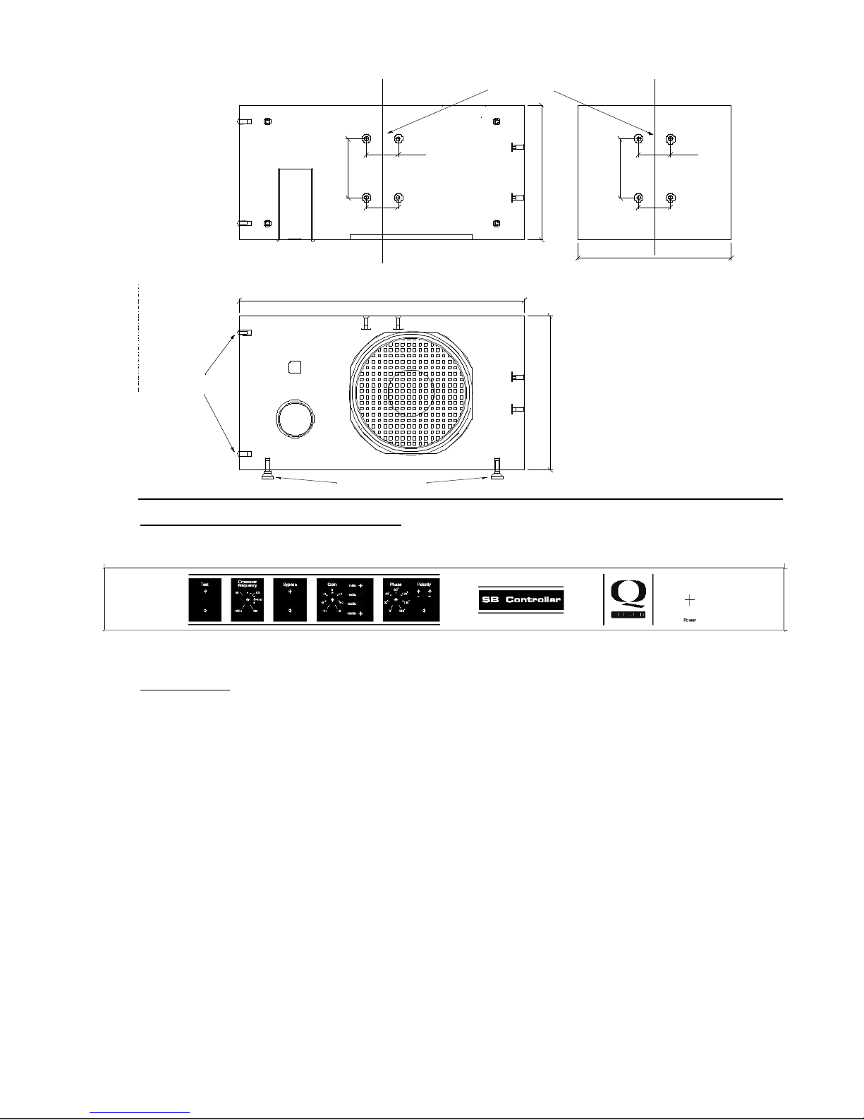
The SB10 has built-in mounting poin ts that are located on two of the sides of the cabinet and are
fo r use with the Quested stands (see diagram). The position of the mounting points are indicated
on the line drawing on page 13 of this manual. When fixing the stand plate to the loudspeaker:
• The bolt length must always penetrate at least 25 mm into th e cabinet base; the minimum
bolt length is 30 mm.
• Always use locking washers and thread lock compound.
• Always use all of the M6 bol ts.
• Because the cabinet is a source of vibration, the bolts must be properly tightened but
caution must be exercised as over-tightening could damage the case. Always tighten the
bolts a li ttle at a time in order to spread the stress over the area of the mounting plate. If a
torque wrench is available the recommended final torque is 6 Nm (4 lbf-feet). A 200 mm
(8”) span ner will achieve the appropriate torque without needing hard work. The mounting
plate holes are sealed by M6 x 1 6 mm nylon countersunk machine screws. These will need
to be removed before the cabinet can be screwed on t o the mounting bracket.
THESE NYLON SCREWS SH OULD NOT BE USED TO MOUNT THE CABINET. THEY ARE
NOT OF
SUFFICIENT STRENGTH. A STEEL MACHINE SCREW OF AT LEAST 30 mm IN LENGTH
SHOULD BE
USED FOR THIS PURP O SE. If the SB10 is subsequently removed from the stand, the mounting
holes will need to be re-sealed using the nylon screws or some other suitable sealan t.
4.3 El ectrica l Con nectio n
4.3.1 Saf ety Earth i ng
This product has been designed to comply with international safety standards. It is
essential tha t t he green/yellow core of the mains cable, or the ground pin of a 3-pin
moulded plug, is connected to the electrical installations safety earth or ground. It is
internally connected to all exp osed met al surfaces an d it is essential for personal
safety as well as proper operation of the product. The audio signal in-put is electronically
balanced and does not need the disconnection of an y safety earth for the avoidance of
hum loo ps.
4.3.2 Vo ltag e S e tting
The set voltage is indicated o n the rear panel of the unit. At this setting there is an
accept able tolerance over which the performance o f the unit will con tinue to meet its
specifications. (See p ower requirements on page 12 of his manual.) For th e 23 0V setting
this is 160V t o 255V and for t he 1 15V set ting it is 80V t o 127V. If the unit is co nnected to
voltages in excess of its maximum, damage is likely to occur which may not be recoverable
from without qualified service attention .
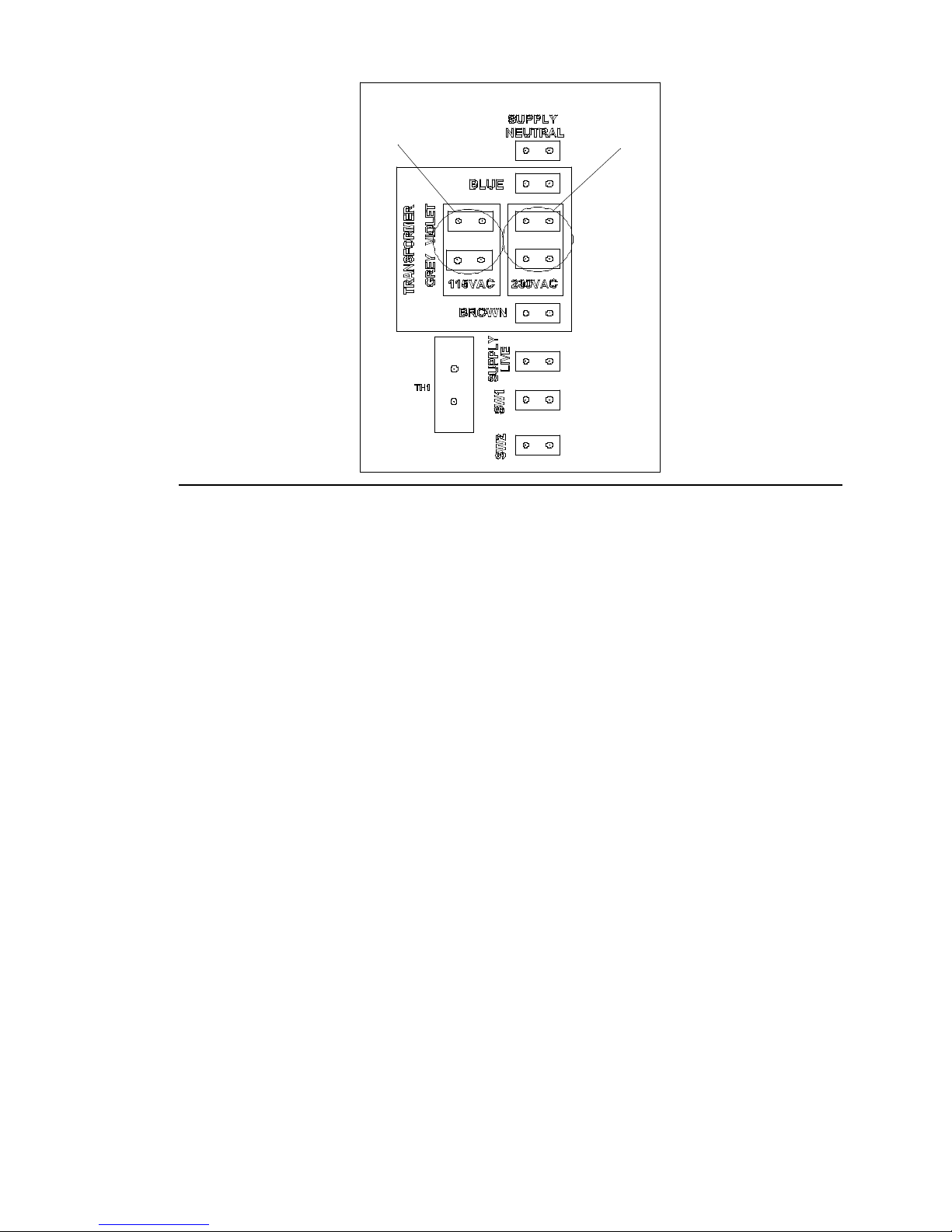
To change the set voltage, the co ver must be removed from the SB Co n troll er. Th e
power and signal cables must be disconnected before continuing. Remove the 10 x M3 T orx
screws from the top cover. Remove the top cover an d you will see 4 wires coming from the
mains transformer and connecting to the main PCB board in an area marked as
“transformer” on the PCB. Bot h t he grey and violet wires must be moved to the desired
voltage tap as marked on the board. Be careful to ensure that the crimps are pushed firmly
home and the coloured wires correspond with the printing on the PCB. Replace the lid using
the 10 x M3 screws. You must now change the fuse located in the IEC inlet socket for the
correct one as indicated on the back panel. It is imp ortan t th at you now mark the rear of
the unit with the new set voltage.
Page 6
6
115V
230V
Exploded view of PC B vi ewed from above s h owi n g th e voltage s e l ectio n
connectors with
alt ern ative pi n s for the 115V and 230V settings .
4.3.3 Fus e Setti ng
It is very unlikely the fuse will fail during normal use but should this occur the situation
must be ap proached with some caution. Check that t he mains voltage set ti ng is correct for
your installation supply and that the original fuse was the correct rating. (See 9.2 Spares)
The fuse may blow if the unit is subjected to mains p ower surges or spikes, or if the mains
wiring has any poor or fault y connections, in which case a qualified electrician should be
consulted. Very occasionally a fuse can become degraded after many years of service and
simply replacing it with a new one will restore the system.
The fuse is housed in a unit integral with the IEC inlet co nnector (see rear panel drawing
page of this manual). To gain access to the fuse remove the power cord and unclip the fuse
carrier using a flat blade. A spare fuse of the correct rating is also provided within t he same
carrier. If none of the above is the cause of th e fault it is likely that t he unit has suffered an
internal co mponent failure and will need returning to a qualified agent for servicing IF THE
REPLACEMENT FUSE SH OULD FAIL DISC ONNECT FROM THE MAINS
IMMEDIATELY AND
HAVE THE UNIT PR OFESSIONALLY REPAIRED BEFORE ATTEMPTING TO USE
IT.
4.4 Audio Con nectio n s
The audio signal inputs are RF filtered and electronically balanced to ensure a high level of
rejection for common mode int erference signals and to give a p rofessional connection to external
equipment . It is essential for optimal use of these specifications th at a professional grade,
balanced two-core screened cable is used. Th e input’s will accept both XLR and ¼ inch type
connectors.
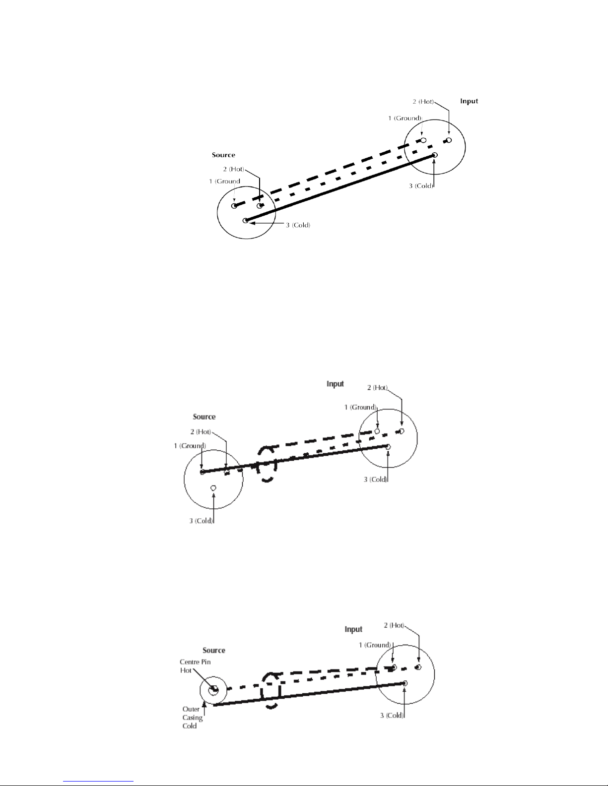
Sourc e Ba la nced Pin 2 hot
In accordance with in ternational standards, 3 -pin XLR style input connectors are used, with pin
2 being designated t he ‘in-phase’ or ‘hot’ terminal and pin 3, the ‘out of phase’ or ‘cold’ terminal.
Pin 1 is connected to the chassis ground and must be connected to t he screen of the audio
Page 7
7
interconnecting cable. This is necessary to ensure p roper compliance wit h European Standards for
Electromagnetic Compatibility. Pin 1 carries no signal voltages or currents and is provided purely fo r
screening purp oses. It should no t be con nected to either pin 2 or pin 3.
Sourc e Unbalanced Pin 2 Hot
If the equipment providing the audio signal has an unbalanced output, then the interconnecting
audio cable should be wired so that the hot output of t he source is connected to pin 2 of speaker
input XLR and the ground of the source connected to pin 3. The screen of the interco nnecting
audio cable should be connected to pin 1 of t he input connector only. There must b e n o
connectio n b etwe e n th e ground co n n ection of th e unbalanc ed o utput a nd t h e pin 1
ground connection of the input conn ecto r.
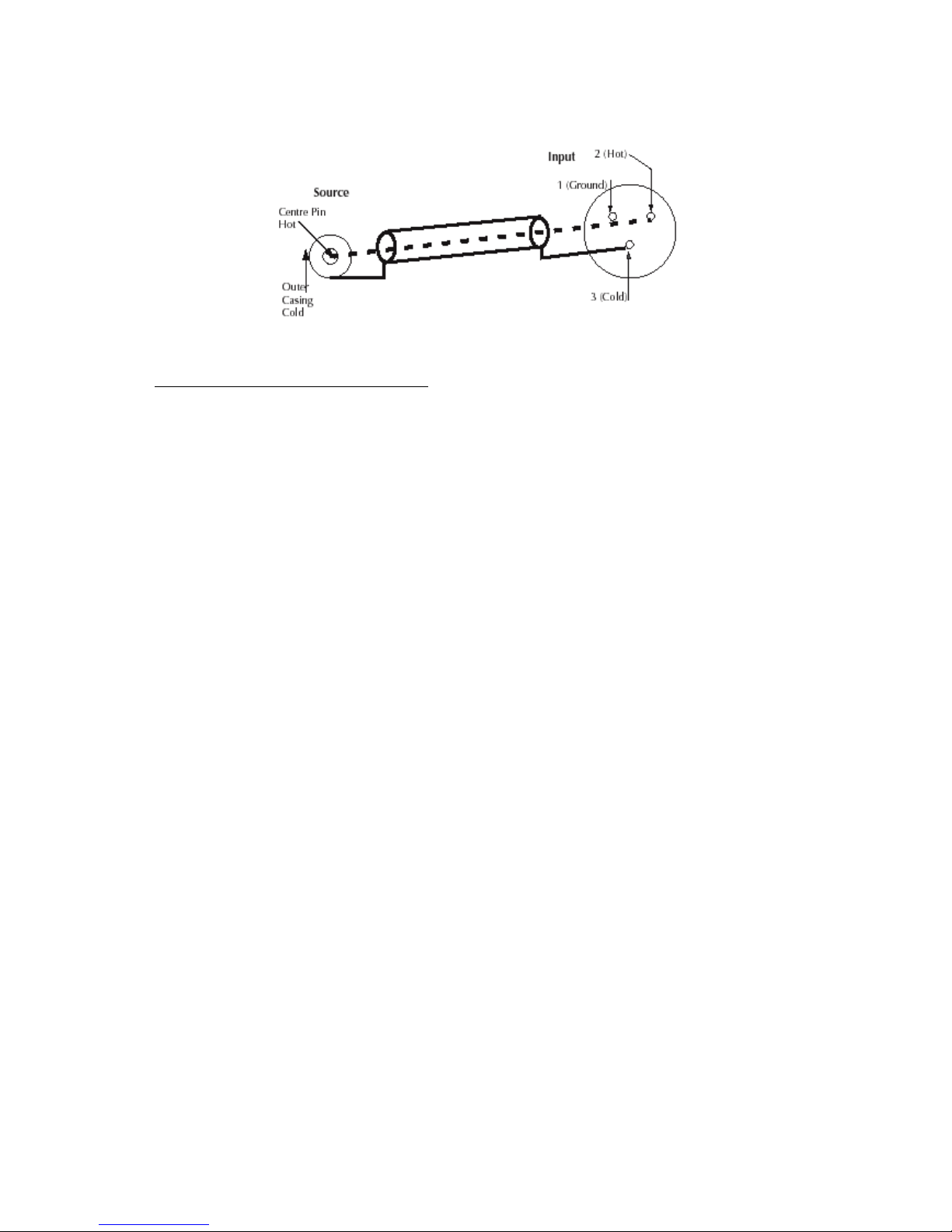
S o urce Unbala nced Pho n o
If the source output is a phono socket, then the cent re pin of the phono plug should be wired to pin
2 of the speaker input XLR and the outer phono casing to pin 3. The wire from pin 1 of the XLR
will not be connected to the terminals of the p hon o plug. Strict adherence to this will help to
eliminate ground loop hums and RF break through.
Page 8
8
Sourc e Unbalanced Pho no 2 Cor e cable
5 OPERATIONAL C ON SIDERATIONS
5.1 Mains O n-Off Switchi ng a nd L ev el
A rocker switch on th e fron t panel provides On-Off switching. When powering up an audio
system it is good practice to start at the source e.g. 1st outboard equipment, 2nd mixer, 3rd
SB10 , 4th lef t and right monitors. When powering down the reverse order should be adopted.
5.2 Front Panel Ind ica tors/Co ntrols
5.3 Test
T he test function is used to set the system up. It sends band limited pink noise to both the
sub bass out put and the full range monit ors. A green LED indicates that the test signal is on.
5.4 Cro s sover Frequ e ncy
T o allow you to accurately match th e SB 10 to differen t monitors, different environments
and
different monito ring requirements the SB controller has adjustable crossover points. These
can be adjusted with t he recessed pot in the front panel by using a flat bladed screwdriver.
T he crossover poin t is sweepable between 40 and 135 Hz. It controls the frequency th e high
pass filters that supply the full range monit ors and th e low pass filter that supplies the sub
bass cross over.
5.5 Bypas s
T his mu tes the sub bass output and bypasses the crossover filters that are on t he full range
monitor out puts. This can be used as a monitoring function, as it allows you to easily switch
between a 2 and 3-way monitoring set up. Th ere is a green LED t hat indicates when the
SB10 is bypassed.
5.6 Gain
T he sub bass amplifier gain can be adjusted with th e recessed po t in the fron t panel by
using a flat bladed screwdriver. This has a range of 20 dBu. With 0 dBu input on 1 channel
and the gain pot set to 0 t he amplifier will give 2 dBu below maximum output. This allows
you to accurately set the output level of the sub bass. 4 LEDs –18, -12, -6 and 0 dbB
indicate the level of the sub bass. The 0db LED indicates that the amplifier is 1 dB below
clip.
5.7 Pha s e
T his con trols the phase of the sub bass and is used on ins tallation to accurately match the
sub bass with bo th the full range monitors and the en vironmen t t hey are being used in. It can
be adjusted between 0 and 180 degrees with the recessed pot in th e front panel by using a
flat bladed screwdriver.
Page 9

9
5.8 Polarity
This con trols the polari ty of t he sub bass. It is used in conjunction with the phase control to
accurately ma tch the sub bass with both the full range monit ors and the environment they
are being used in. Two green LED’s indicate when th e sub bass polarity is both p ositive and
negative.
5.9 Power
On and off.
5.10 Rear Panel Co ntrols
Left input filter bypass
A recessed switch on th e rear panel allows the left input filters to be bypassed changing the
left input to full range. A full range input should be used for a LFE source that has been
ex ternally filtered. This switch should be used with caution. The SB10 sh ould never be used
without any low pass filters. To use the SB1 0 without any low pass filters is likely to cause
damage to the drive unit. This is because the cabinet has a large resonance that is out of
t he n ormal o perating bandwidth.
5.11 Internal S ett i n g s
S ub sonic/Hig h pass filt er
It is possible t o change the subsonic/high pass filter from 14-28 Hz with internal jumpers.
T here sh ould be no need to alter t his, as the unit will be shipped configured correctly for use
with y our unit. This fil ter is used to gain more amplifier headroo m if the speakers operating
bandwidth is above 28 HZ. IF this setting is to be changed, firstly disconnec t all power and
signal leads. Remove the cover of the SB controller using a Torx driver. Locate t he 4 jumpers
t ha t are clearly marked and located on the main PCB behind the gain and phase pots. To fit
all of the jumpers will set the high pass filter to 28 Hz and to remove them all will set it to
14
Hz.
6 SETTING UP: THE WHYS AND HO W S O F SUBWO OFER USE
6.1 WHY?
The SB1 0(s) can be incorporated int o a compact stereo mo nitor sys tem to eit her extend
the system low frequency response, or increase the maximum system SPL, or to achieve
combination of both. Additionally SB10s can be utilised to reproduce the L.F.E. or .1
element
of a multi-channel system. In order to meet t hese objectives it is impor tan t t hat some
though t
is given to th e positioning of the SB10(s) and that care is taken with the adjustment of the
crossover frequency , phase and relative levels.
T he performance of any loudspeaker in a t ypical room will be, to an extent , dependant upon
its position. This is particularly true of subwoofers as low frequencies are more susceptible to
changes of cabinet position than high o nes. There is a common misconception t hat bass is
not directio nal, th e trut h is t hat as the frequency lowers the less directional it becomes. For
this reason the higher the low pass frequency of the subwoofer the more critical its positio n
relative to the rest of the monitor system. If part o f a program being played has transient
low
frequency componen ts e.g. a kick drum, bad positioning of t he SB10 will be particularly
evident.
6.2 HO W?
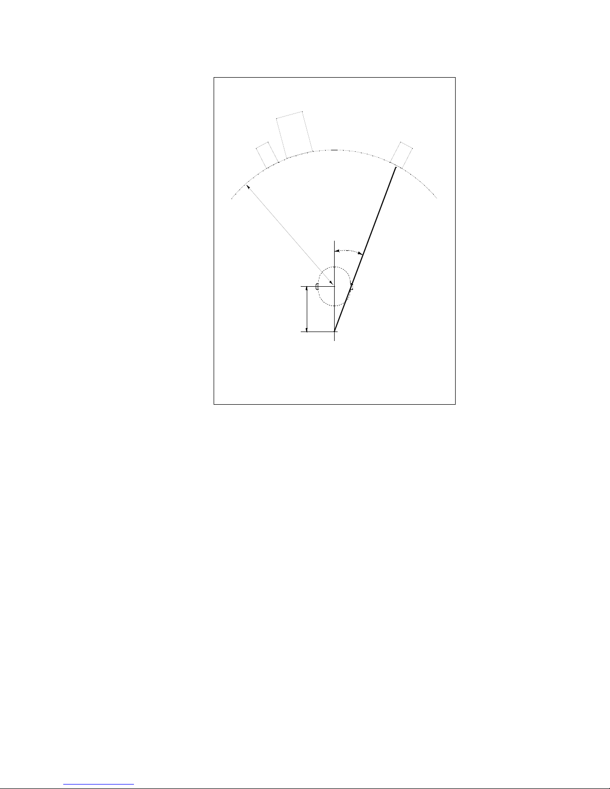
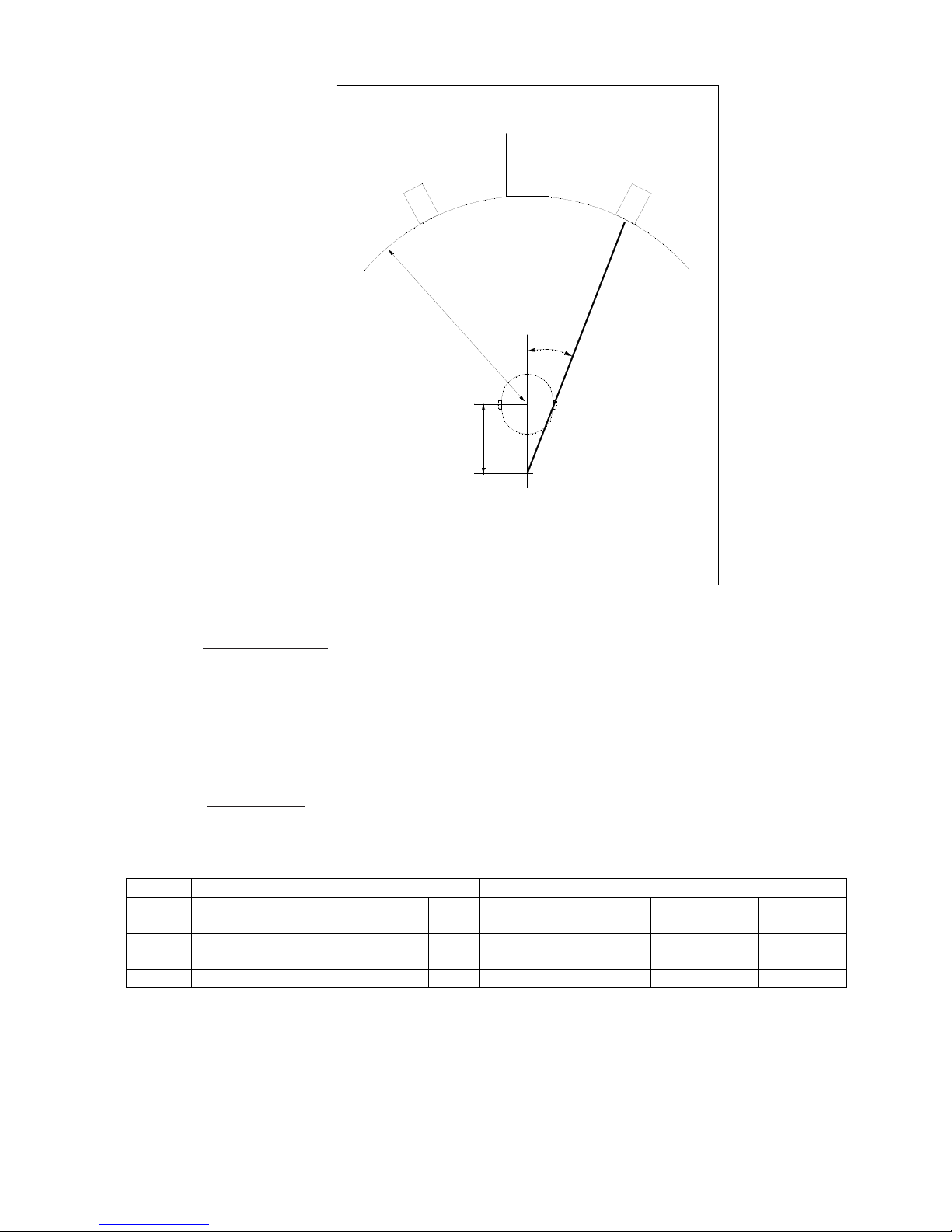
Posi tioning: Typical examples of stereo installations with a pair of S6 near-field monitors
and
a single SB 10 are illustrat ed in Figs 1 & 2. The nearfield monitors are 120 cm from the
listening p osition and the SB10s are sited between the left and right monitors. Ideal
placemen ts would be as in Fig. 1 for symmetrical room layouts and as in Fig. 2 for
asymmetric room layouts. In both examples t he SB 10s are on the same radius as the
left and right monitors and the centre of the arc is the listening position. To obtain the most
Page 10
10
stable imaging and to maximize the area of the “sweet spot”, the axis of the left and right
monitors should cross at a point approximately 40 cm behind the listening p osition.
25
o
120cm
S6
S6
SB10
40cm
Speaker directed at a point
approximately 40cm behind
listening position
Diagram shows a symetrical room layout. The system is set up centrally
in the room, therefore the SB10 has been placed closer to the left hand
monitors, which allows the SB10 to be away from the room's centre.
Fig 1
Page 11
11
25
o
120cm
S6
S6
SB10
40cm
Speaker directed at a point
approximately 40cm behind
listening position
Diagram shows asymetric room layout. The system is not set up centrally
in the room, therefore the SB10 has been placed in the middle between the
left and right monitors, but this still allows the SB10 to be away
from the room's centre.
Fig 2
Audio connections: The audio source is connected to the left and right inputs o f the SB10
Controller. The left and right outputs of the controller are connected to the inputs of the lef t
and right mo nitors. Connect the SB10 Con troller to the SB10 wit h as shor t a length of good
quality speaker cable as is practical. It is important that speaker cables are twisted, shielded
or at least run closely paralleled to reduce loops conducting RF currents.
When powering up an audio system it is good p ractice to start a t the source, e.g. 1
st
outboard
equipment, 2nd mixer, 3rd S B10 , 4th left and right monitors. When powering down the reverse
order should be adopted.
Getting star ted: The following are approximate set tings for combinations of the SB10 with
S6, S7, and S8. Th e overall gain structure will depend on y our source levels. You should set
the full range mo ni tor gains so as you are comfortable with the maximum level achievable
from your source. You can then bring the SB10 gain up to match
S-S e ri es
S10
Gain
L.F.
Compensation
Gain
Crossover Frequency
Phase
Polarity
S6
-12/#6*
flat
0
60Hz
0
+
S7
-12/#6*
-2
0
50Hz
0
+
S8
-12/#6*
-4
0
40Hz
0
+
* #6 shows the number on th e switch position rather than t he screen-printing
T he above settings are for the highest sonic performance of the system. Raising the
crossover frequency would result in increased head room in the bass driver and allow for
higher maximum system spl. However the response would not be as smooth, the imaging not
so precise.
Page 12
12
A final alignment should be executed when th e exact position of the monitoring has been
determined and any furni ture, soft furnishings and/or carpet are in place. To carry out an
accurate alignment it is necessary t o use professional test equipmen t, a real time spectrum
analyzer would be the best op tion for most users. A spectrum analyzer (AL1), signal source
(MR1), signal switching box (SB1) and measurement micropho ne (ML1) can be obtained
from selected Quested distributors.
Accurate system alignmen t: Place the measurement microphone at the listening posi tion,
Facing it forward. This is a point at ear height in t he central listening position, see fig 1 or 2
on page 10. Correct mic placement is critical to achieve reliable results. Co nnect t he
microphone via an XLR cable to th e analyzer (AL1). Connect t he
signal source (MR1) to t he left and righ t inputs of the SB Controller via the switching box
(SB1). The analyzer needs to be easily visible whilst the SB10 Controller and signal source
are adjusted.
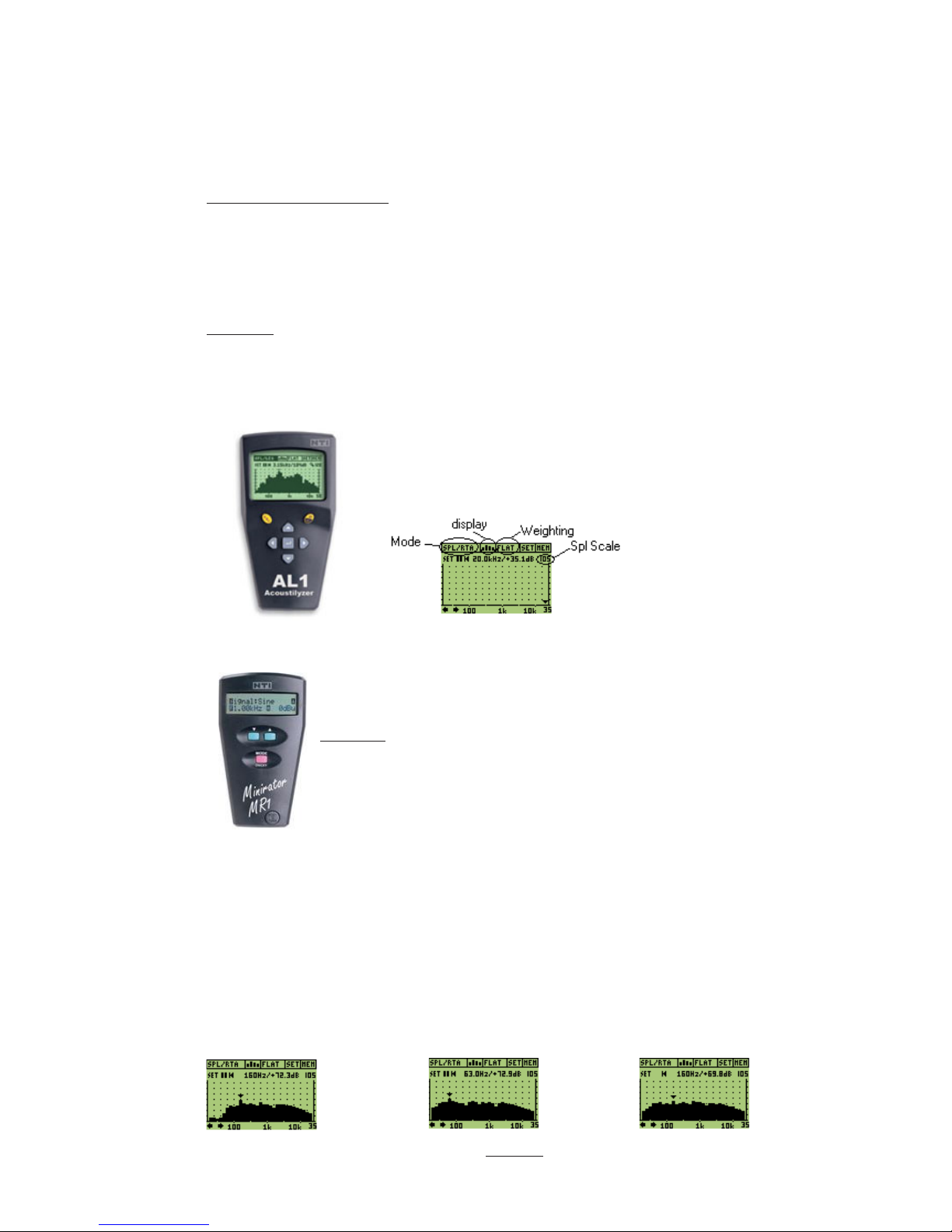
T he AL1: Turn the unit on, select setup 1 , which will display SPL/RTA. At the top right
hand
corner of the screen set the full scale spl level to 105. Set the weighting, which is just to the
right of top/center of the screen to FLAT. Set the display t o RTA which is just to t he left of
the top/ center
AL1 This is the AL1 display set up cor rectly
The MR1: Turn the unit on, select signal:P.Noise, set t he amplitude to A
moderate level between - 24 and —14 dBu.
Before you att emp t t o align the system, familiarize yourself with the cont rols o n the front of
the SB10 Controller and the effects that t hey have. By switching the bypass co ntrol you will
be able to compare the unfiltered response of your monitor system with out the con tribution
of the SB 10 to that of the co mbination. Switch off the main speakers to listen t o t he effect
that adjusting the crossover frequency con trol has on the response of the S B10 .
If t here are any large dips or peaks in the response, t he SB 10 cabinet can be rep ositioned t o
minimize them.
Now that you are familiar with the units send the pink noise to the left speaker, adjust the
level on the SB10 Con troller to obtain the flattest response on the analyzer.
Display showing 1 S6 Display showing 1 S6 Display showing 1 S6
With the sub bypassed and 1 SB10 Bass to high and 1 SB10 with flat r esponse
Page 13

13
You now need to obtain maximum output of the speaker combination at the crossover
point
by means of the phase potentio meter and polarity switch. It is usually easier to adjust for
maximum cancellation (lowest output) and then reverse the p olarity switch to obtain
maximum output. If there is a bump or lift in the respo nse at the crossover poin t, roll off t he
bass response of the full range cabinet by using the LF Compensation switches on the left
and right mo nitors. Send pink noise to both the left and right inputs. Slowly turn the phase
pot looking for maximum cancellation. Now reverse the polarity and turn the phase pot
again
looking for maximum cancellation. You should be able to see t here is a lot mo re cancellation
with t he polarity set to either + or – whilst adjusting the phase pot. Reset it to wherever the
greates t cancellation was. Now reverse the polarit y, this will give you maximum output.
Display showing maximum Display showing finished
Obtainable cancellation. Result (polarity rev ers ed f rom
Maximum cancellation)
Your system is now co nfigured and ready for use. There should be no need to adjust the phase
or polarit y any more. You can, and may want to turn the sub up or down a lit tle aft er using
the system.
Systems with two S B10s: Connect the out puts of th e SB1 to each of the subwoofers,
co nnect each subwoofer to its co rresponding full range cabinet. Proceed with the Accurate
system alignment.
It is now necessary to con firm tha t t he subwoofers are completely in phase with each oth er.
One subwoofer needs to be aligned to the o ther. If when aligning the subwoofers to the full
range cabinets ei ther the left or right was easier to interpret, choose this as the master, if not
take your choice.
Disconnect the full range cabinets, send the pink noise to both sub woofers. Reverse
the
p olarity on the SB10 controller th at is not the mas ter. Adjust the phase on this con troller
t o obtain the lowest output of th e combined sub woofers. Switch the polarity on the same
co ntroller back to its original position, the p hase of the two sub woofers is accurately
adjusted.
7 SB 10 Tec h nica l Spec i ficatio n
Size (w x h x d) 617 x 333 x 2 90 (SB Controller - 1U case 270mm deep)
Weight 19.8 kg (SB Controller – 5.5 kg)
Driver Bass cone 1 x 250mm (10”)
Frequency Response User Adjustable
INPU T
Connector: 2 o ff XLR and ¼ inch jack combo socket
Impedance: 10k electronically balanced
Wiring: Pin 1 (Sleeve) ground, Pin 2 (Tip) h ot, Pin 3 (Ring) cold
Gain: -14 dBu to +6 dBu
OUTPU TS
Left and right monitor 2 off XLR3 type male left & right
outputs
Impedance <100 ohm electronically balanced
Wiring Pin 1 ground, Pin 2 h ot, Pin 3 cold
Sub Bass output 1 pair binding posts
Page 14

14
FIL TERS
Left & right input summed to sub out put
Subsonic/High pass: -3dB @ 14Hz, 24dB/oct o r -3dB @ 28Hz, 24dB/oct (set by
internal
jumper)
Low Pass -3dB @ 40Hz to 135Hz, ex ternally adjustable @ 24db /oct or full
range on CH A
Left right input to left & right output
Ultra sonic -1dB @ 100k
High pass -3dB @ 40Hz to 135Hz, ex ternally adjustable @ 24db /oct or full
range on CH A
POWER AMPLIFIER > 210 W rms continuous
THD < 0.03% a t levels up to 1dB below clip, 20Hz - 120Hz typ 0.005%
@ 20 W rms 100 Hz
Hum + Noise < -1 00dB referred to clip
CONTROLS: Crossover Frequency 40 – 135Hz, front panel pot
Test (Band limited pink noise), front panel recessed switch (LED
indicates when on)
Sub bass bypass, front p anel switch (LED indicates when bypassed)
Sub Gain –1 4 to +6, front panel pot (Sub level indicated with LED
Meter)
Sub Phase, front panel pot
Sub Polari ty, front panel recessed switch (LED indication for
positive
and negative p olarity )
P ower, fron t panel switch
Left channel sub filter bypass, rear mounted recessed switch
Subsonic fil ter 14 or 28Hz, Internal jumpers
POWER REQUIREMEN TS
Voltage: Set by in ternal plug: nominal 115V or 230V @ 50-60Hz AC
230V setting: Min 160V (restricted
output power): Max 255V
115V setting: Min 80V (restricted output power): Max 127V
CONSUMPTION
Quiescent: <30 W
Typical use: 50 W
Max: <200 W
Note 0dBu = 775mV into open circuit
This product is built to conform to the requirements for CE marking.
8 SB1 0 LINE DRAWING
Page 15
15
127mm
or 5"
127mm
or 5"
69,50mm
or 2.75"
69,50mm
or 2.75"
290
332,0mm
617.0mm
C
L
C
L
332.0mm
Fixing points for
feet or spikes
Fixing points for feet or spikes
Stand mounting point
8 SB1 0 CONTROLLER LINE DRAWING
9 GUARANTEE
The SB contro l l er electronics are guaranteed for 5 years from date o f purchase. All other parts are
guaranteed for 24 mont hs. If any par t of the product is found to be defective because of faulty
manufacture within these periods, Quested, through its authorised distribution network, will effect
repair or replacemen t, at its discretion , free of charge providing that:
a) T he fault is rep or ted to the authorised distributor.
b) Proof o f purchase is provided.
c) T he fault is no t caused by misuse, neglect or faulty operation by the user.
d) The fault is not a result of fair wear and tear.
e) T he equipment has not been modified in any way.
f) The equipment has not been taken apart or tampered with in an yway oth er
than described in the service manual fo r the adjustment and
replacement
of user accessible items.
The guarantee does no t co ver:
a) Damage during transit
b) Damage to cones and other speaker parts as a result of the o ver-driving of
the monitors or by faulty installation or connection.
c) Damage caused by incorrect ins tallation or during installatio n caused by
incorrect handling.
d) The cost of carriage to or from the authorised repairer.
Page 16

16
10 APPENDIX
10.1 Accessori es
Omni mount™ plus fixings
Quested S series stands (with unique coupling system)
10.2 Spares
Descriptio n Part Nu mber
LS2529G 10" Bass Driver Q01-0038
Fuses T3.15A L01-0010
Fuses T6.3A L01-0018
10.3 Driver r eplace m ent proc edure
if it is necessary to replace the bass driver, place the cabinet on its rear and, using a 4 mm
hex head driver, remove all of the bolts. As with most objects held by a series of bolts, these
bolts should initially be loosened a lit tle, one at a time rather than each bolt being fully
removed whilst the o ther bolts remain fully tightened. When replacing the bass driver, the
gasket behind the driver should be replaced with the new gasket that will be supplied with
your new driver.
 Loading...