

Page 1

GV50VC User Manual
GV50VC User Manual
CDMA2000-1X/GPS Tracker
TRACGV50VCUM001
Version: 1.01
GV50VC
TRACGV50VCUM0010
Page 2

GV50VC User Manual
Document Title
GV50VC User Manual
Version
1.01
Date
2016-03-18
Status
Release
Document Control ID
TRACGV50VCUM001
General Notes
Queclink offers this information as a service to its customers, to support application and
engineering efforts that use the products designed by Queclink. The information provided is
based upon requirements specifically provided to Queclink by the customers. Queclink has
not undertaken any independent search for additional relevant information, including any
information that may be in the customer’s possession. Furthermore, system validation of
this product designed by Queclink within a larger electronic system remains the
responsibility of the customer or the customer’s system integrator. All specifications
supplied herein are subject to change.
Copyright
This document contains proprietary technical information which is the property of Queclink.
The copying of this document, distribution to others, and communication of the contents
thereof, are forbidden without express authority. Offenders are liable to the payment of
damages. All rights are reserved in the event of a patent grant or registration of a utility
model or design. All specifications supplied herein are subject to change without notice at
any time.
Copyright © Queclink Wireless Solutions Co., Ltd. 2016
WARNING: The device complies with part 15 of the FCC Rules. Operation is subject to the
following two conditions:
(1) The device may not cause harmful interference, and
(2) The device must accept any interference received, including interference that may cause
undesired operation.
Change or modification not expressly approved by the party responsible for compliance
could avoid the user’s authority to operate the equipment.
FCC RF Exposure Statement:
For the product, under normal use condition is at least 20cm away from the body of the user,
the user must keeping at least 20cm distance to the product.
TRACGV50VCUM0011
Page 3

GV50VC User Manual
Contents
Contents ............................................................................................................................................ 2
Table Index ........................................................................................................................................ 3
Figure Index ....................................................................................................................................... 4
0. Revision history ............................................................................................................................. 5
1. Introduction .................................................................................................................................. 6
1.1. Reference ........................................................................................................................... 6
1.2. Terms andAbbreviations..................................................................................................... 6
2. Product Overview .......................................................................................................................... 7
2.1. Appearance ........................................................................................................................ 7
2.2. Interface Definition ............................................................................................................ 7
2.3. LED Description .................................................................................................................. 8
2.4. Power Connection .............................................................................................................. 8
2.5. Ignition Detection............................................................................................................... 9
2.6. Digital Output/ Input connection ..................................................................................... 10
2.7. Digital Output ................................................................................................................... 12
3. GettingStarted ............................................................................................................................. 14
3.1. Part List ............................................................................................................................. 14
3.2. GV50VC External Cable Interface ..................................................................................... 14
3.3. Turn on/Turn off ............................................................................................................... 15
4. Troubleshooting and Safety Info ................................................................................................. 16
4.1. Troubleshooting ............................................................................................................... 16
4.2. Safety Info ........................................................................................................................ 16
TRACGV50VCUM0012
Page 4

GV50VC User Manual
Table Index
TABLE 1: GV50VC PROTOCOL REFERENCE ................................................................................................ 6
TABLE 2: TERMS AND ABBREVIATIONS .................................................................................................... 6
TABLE 3: DESCRIPTION OF 7PIN CONNECTIONS ....................................................................................... 8
TABLE 4: LED DESCRIPTION ...................................................................................................................... 8
TABLE 5: ELECTRICAL CHARACTERISTICS OF IGNITION DETECTION ......................................................... 9
TABLE 6: ELECTRICAL CHARACTERISTICS AS DIGITAL OUTPUTS ............................................................. 10
TABLE 7: ELECTRICAL CHARACTERISTICS AS DIGITAL INPUTS ................................................................ 11
TABLE 8: ELECTRICAL CHARACTERISTICS AS DIGITAL OUTPUTS ............................................................. 12
TABLE 9: PART LIST ................................................................................................................................. 14
TABLE 10: GV50VC USER CABLE COLOUR DEFINITION ........................................................................... 14
TRACGV50VCUM0013
Page 5

GV50VC User Manual
Figure Index
FIGURE 1: GV50VC APPEARANCE ............................................................................................................. 7
FIGURE 2: THE 7 PIN CONNECTOR ON THE GV50VC ................................................................................ 7
FIGURE 3: TYPICAL POWER CONNECTION ................................................................................................ 9
FIGURE 4: TYPICAL IGNITION DETECTION............................................................................................... 10
FIGURE 5: AS DIGITAL OUTPUT INTERNAL DRIVE CIRCUIT ..................................................................... 10
FIGURE 6: TYPICAL CONNECTION WITH BUZZER AS DIGITAL OUTPUT................................................... 11
FIGURE 7: TYPICAL CONNECTION AS DIGITAL INPUT ............................................................................. 11
FIGURE 8: DIGITAL OUTPUT INTERNAL DRIVE CIRCUIT .......................................................................... 12
FIGURE 9: TYPICAL CONNECTION WITH RELAY ...................................................................................... 13
TRACGV50VCUM0014
Page 6

GV50VC User Manual
Revision
Date
Author
Description of change
1.00
2016-03-18
Docter Xu
Initial Version
0. Revision history
TRACGV50VCUM0015
Page 7
GV50VC User Manual
SN
Document name
Remark
[1]
GV50VC @Track Air Interface Protocol
The air protocol interface between
GV50VC and backend server.
Abbreviation
Description
AGND
Analog Ground
AIN
Analog Input
DIN
Digital Input
DOUT
Digital Output
GND
Ground
MIC
Microphone
RXD
Receive Data
TXD
Transmit Data
SPKN
Speaker Negative
SPKP
Speaker Positive
1. Introduction
The GV50VC is a powerful GPS locator designed for vehicle or asset tracking. It has superior
receiver sensitivity, fast TTFF (Time to First Fix) and supports Dual-Band CDMA2000-1x
frequencies 800/1900, its location can be monitored in real time or be periodically tracked
by a backend server or other specified terminals. The GV50VC has multiple input/output
interfaces that can be used for monitoring or controlling external devices. Based on the
integrated @Track protocol, the GV50VC can communicate with a backend server through
the CDMA2000-1x network to transfer reports of Emergency, geo-fence boundary crossings,
low backup battery or scheduled GPS position as well as many other useful functions. Users
can also use GV50VC to monitor the status of a vehicle and control the vehicle by its external
relay output. System Integrators can easily setup their tracking systems based on the
full-featured @Track protocol.
1.1. Reference
Table 1: GV50VC Protocol Reference
1.2. Terms and Abbreviations
Table 2: Terms and Abbreviations
TRACGV50VCUM0016
Page 8
GV50VC User Manual
2. Product Overview
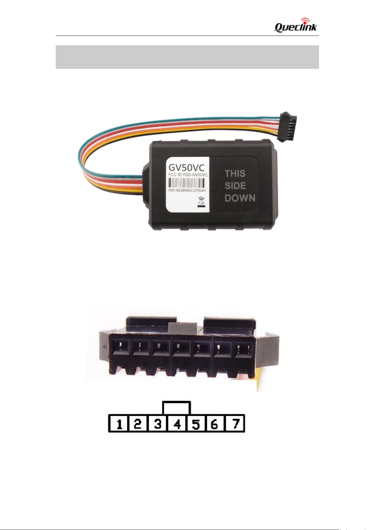
2.1. Appearance
Figure 1: GV50VC Appearance
2.2. Interface Definition
The GV50VC has a 7 PIN interface connector. It contains the connections for power, I/O. The
sequence and definition of the7PIN connector are shown in following figure:
TRACGV50VCUM0017
Figure 2: The 7 PIN connector on the GV50VC
Page 9

GV50VC User Manual
Index
Description
Comment
1
RXD
UART RXD ; TTL
2
TXD
UART TXD ; TTL
3
VIN
External DC power input,8-16V
4
IGN
Ignition input, positive trigger
5
OUT1/IN1
Digital Output/ Input
6
OUT2
Open drain,150mA max
7
GND
GND
CELL
(note1)
Device is searching CELL network
Fastflashing
Devicehas registered to CELL network.
Slow flashing
GPS
(note 2)
GPS chip is powered off
OFF
GPS sends no data or data format error
Slow flashing
GPS chip is searching GPS info.
Fast flashing
GPS chip has gotten GPS info.
ON
Table 3: Description of 7PIN Connections
2.3. LED Description
GV50VC has two status LED which contain CELL LED and GPS LED.
Table 4: LED Description
Note:
1 – CELL LED cannot be configured.
2 - GPS LED can be configured to turn off after a period of time using the configuration tool
3 - Fast flashing is about 60ms ON/ 780ms OFF
4 - Slow flashing is about 60ms ON/ 1940ms OFF
5 –When LED ON is 0, each time the device powers on, both LED’s will work for 30 minutes
and then are turned off deadly
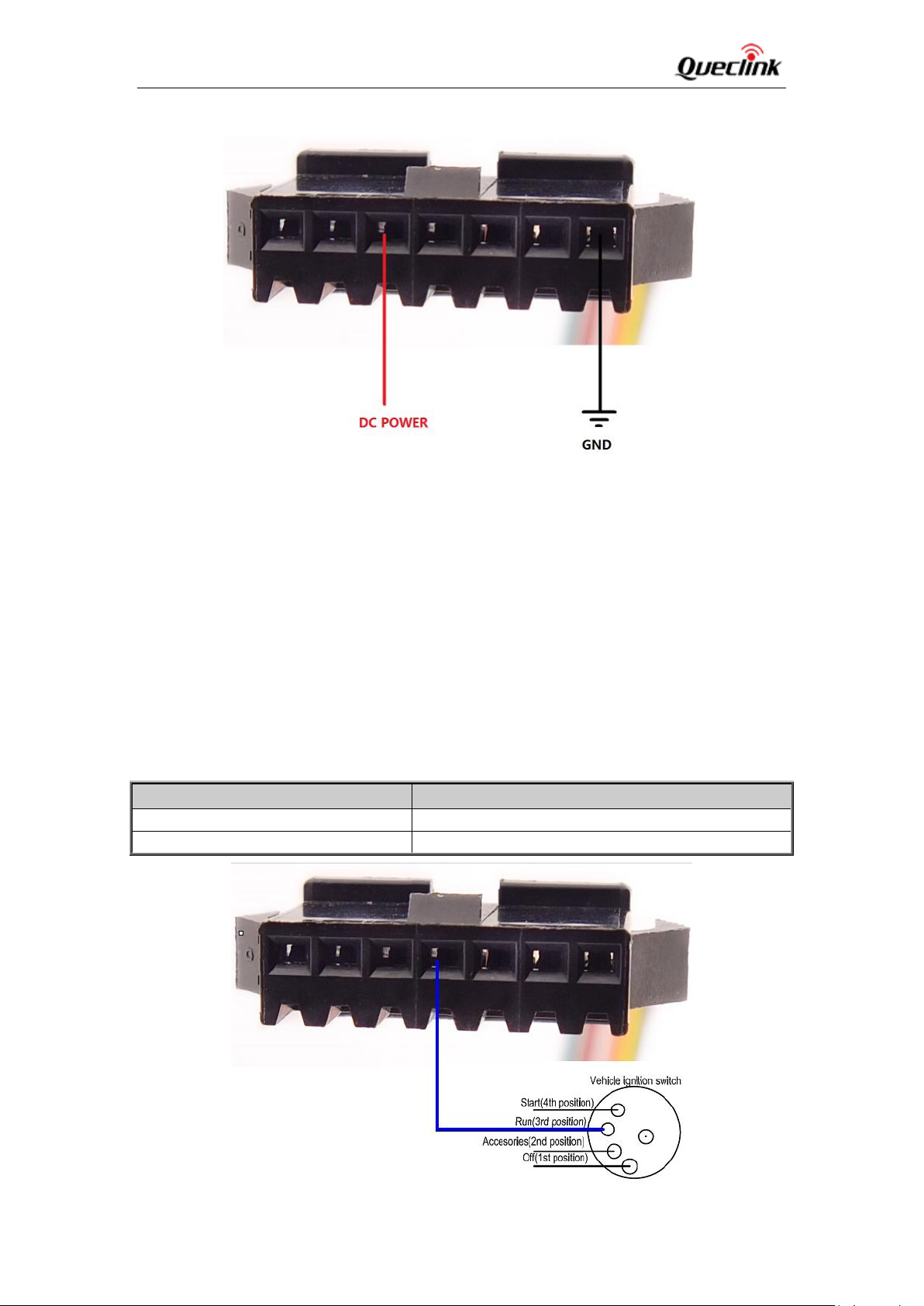
2.4. Power Connection
VIN(PIN3)/GND(PIN7) are the power input pins. The input voltage range for this device is
from 8V to 16V. The device is designed to be installed in vehicles that operate on 12Vvehicle
without the need for external transformers.
TRACGV50VCUM0018
Page 10
GV50VC User Manual
Logical State
Electrical State
Active
5.0V to 32V
Inactive
0V to 3V or Open
Figure 3: Typical Power Connection
2.5. Ignition Detection
IGN (Pin4) is used for ignition detection. It is strongly recommended to connect this pin to
ignition key “RUN” position as shown up.
An alternative to connecting to the ignition switch is to find a non-permanent power source that
is only available when the vehicle is running. For example the power source for the FM radio.
IGN signal can be configured to start transmitting information to backend server when ignition is
on, and enter power saving mode when ignition is off.
Table 5: Electrical Characteristics of Ignition Detection
TRACGV50VCUM0019
Page 11
GV50VC User Manual
Logical State
Electrical Characteristics
Enable
<1.5V @150mA
Disable
Open drain
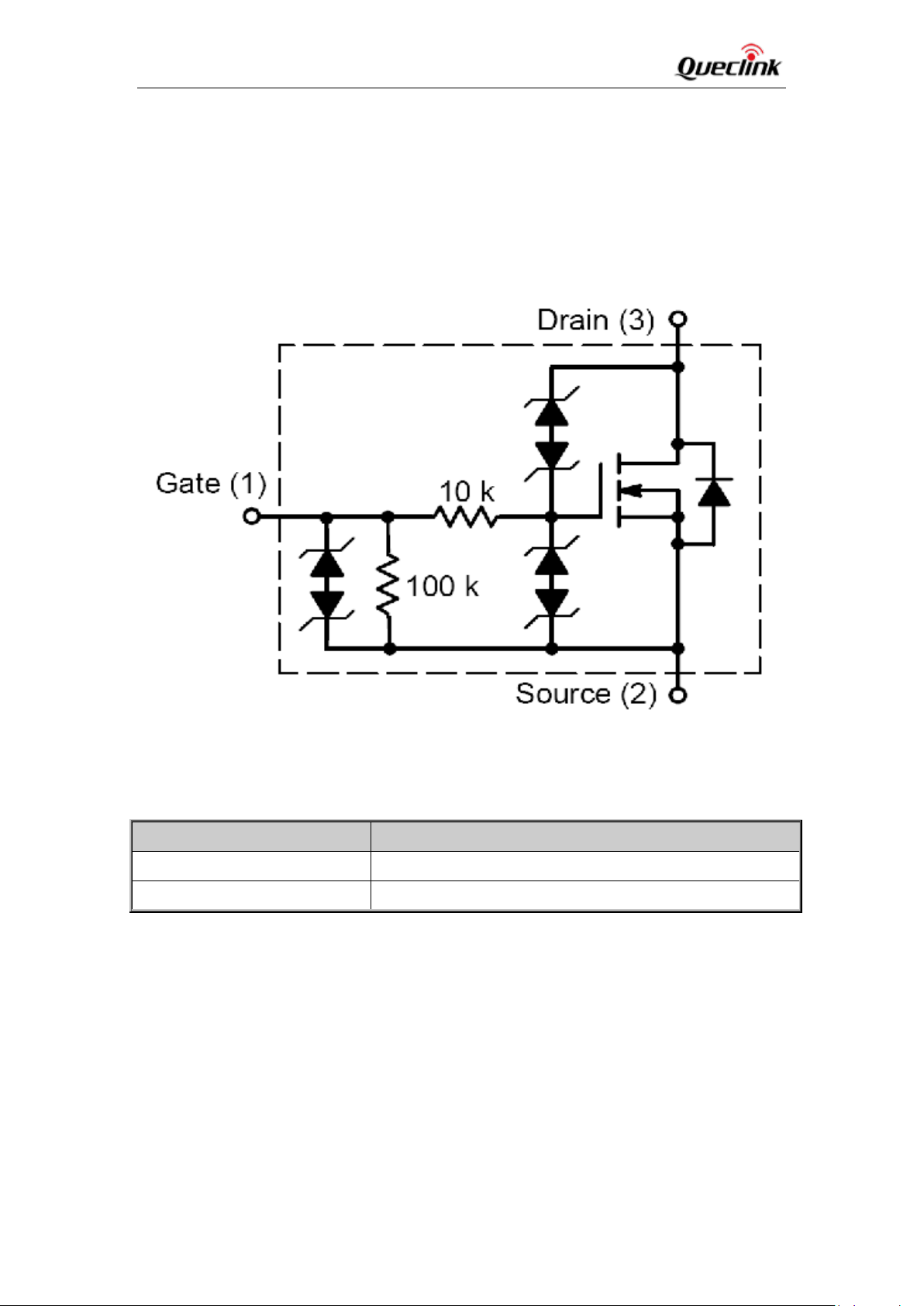
2.6. Digital Output/ Input connection
Figure 4: Typical Ignition Detection
OUT1/IN1(PIN5) is a digital Output/Input connection on GV50VC.Ti is of open drain type and
the maximum drain current is150mA as a digital Output and a negative trigger as digital
Input Electrical Characteristics of the digital input.
Figure 5: As Digital Output Internal Drive Circuit
Table 6: Electrical Characteristics AS Digital Outputs
TRACGV50VCUM00110
Page 12

GV50VC User Manual
Logical State
Electrical Characteristics
Active
0V to 0.8V
Inactive
Open
Figure 6: Typical Connection with buzzer AS Digital Output
Table 7: Electrical Characteristics AS Digital Inputs
The following diagram shows the recommended connection of a digital input.
TRACGV50VCUM00111
Figure 7: Typical Connection AS Digital Input
Page 13
GV50VC User Manual
Logical State
Electrical Characteristics
Enable
<1.5V @150mA
Disable
Open drain
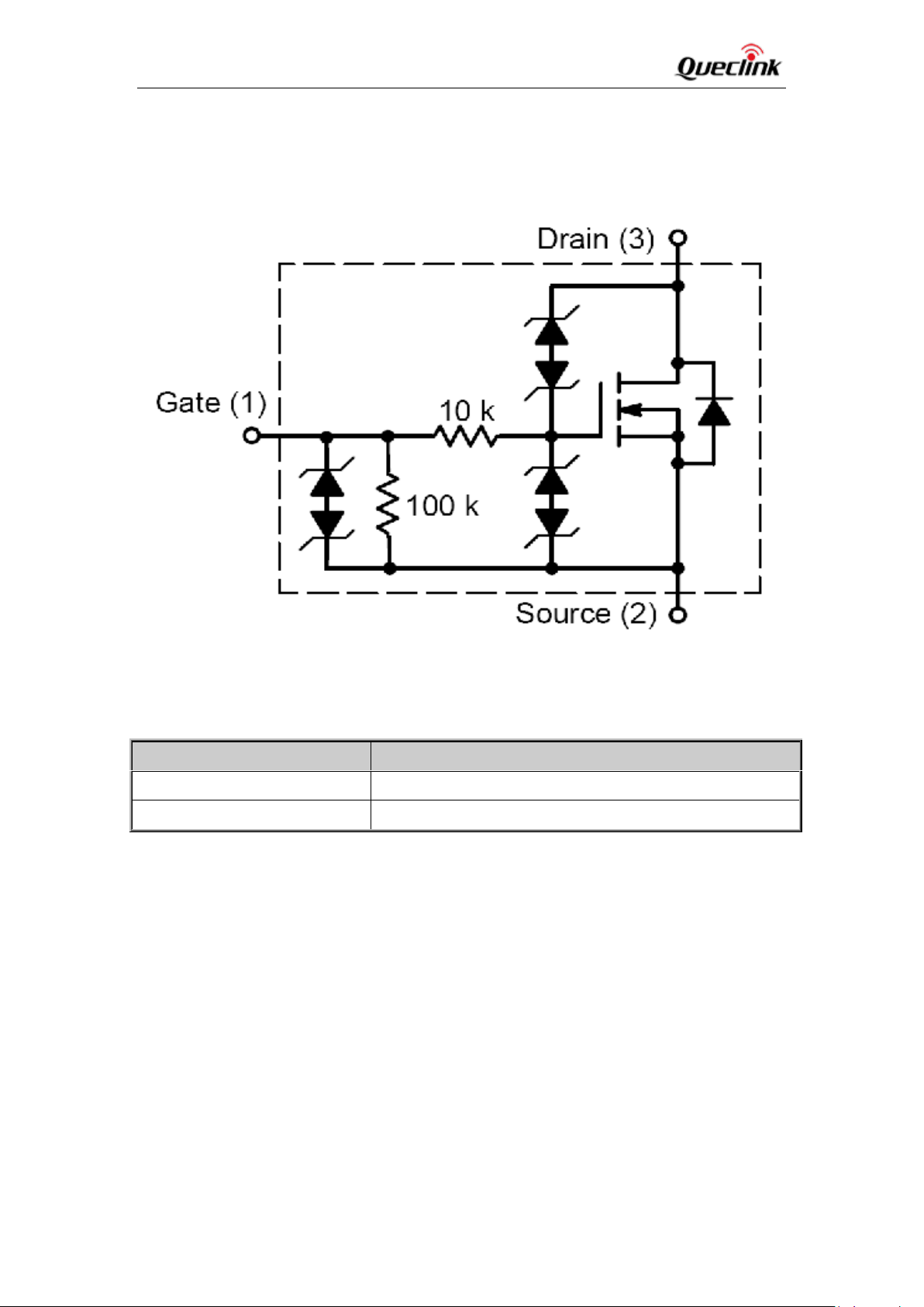
2.7. Digital Output
There is a digital output (PIN6) on GV50VC. Ti is of open drain type and the maximum drain
current is 150mA.
Figure 8: Digital Output Internal Drive Circuit
Table 8: Electrical Characteristics AS Digital Outputs
TRACGV50VCUM00112
Page 14

GV50VC User Manual
Figure 9: Typical Connection with Relay
TRACGV50VCUM00113
Page 15
GV50VC User Manual
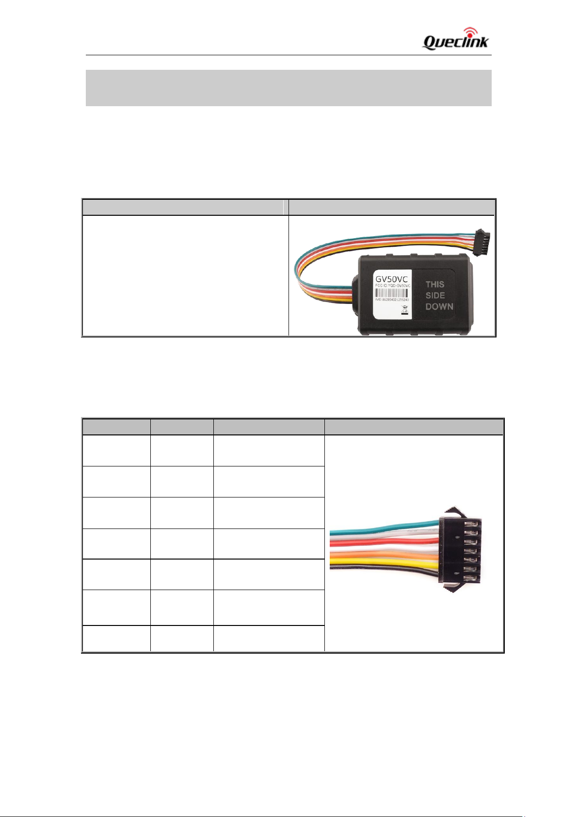
Name
Picture
GV50VC Locator
73mm*50mm*13.2mm
Definition
Colour
PIN No
Cable
RXD
Green
1
TXD
Gray
2
VIN
Red
3
IGN
White
4
OUT1/IN1
Orange
5
OUT2
Yellow
6
GND
Black
7
3. GettingStarted
3.1. Part List
Table 9: Part List
3.2. GV50VC External Cable Interface
Table 10: GV50VC User Cable Colour definition
TRACGV50VCUM00114
Page 16

GV50VC User Manual
3.3. Turn on/Turn off
Turn On: Connect device to external battery, and it will turn on automatically, PWR LED will
light on.
Turn Off: Disconnect device from external battery, and it will turn off.
TRACGV50VCUM00115
Page 17
GV50VC User Manual
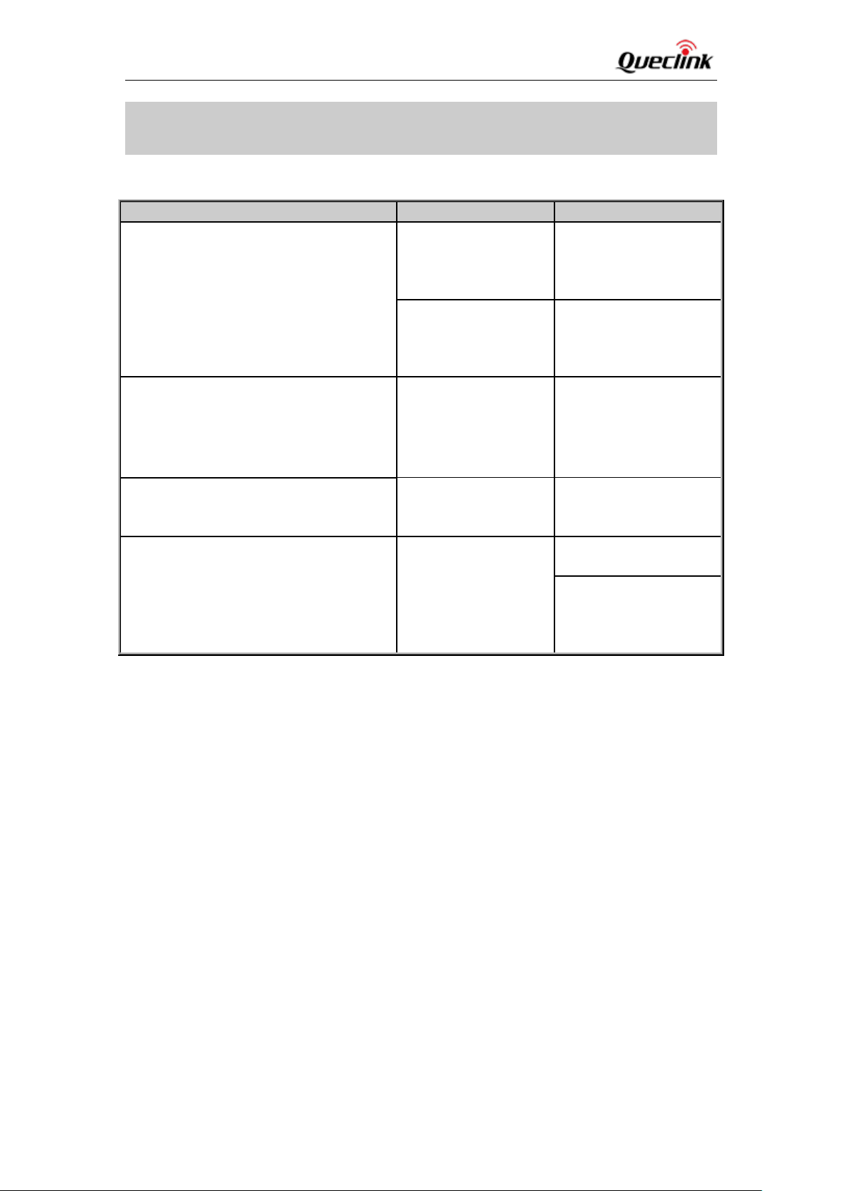
Trouble
Possible reason
Solution
After GV50VC is turned on, the CELL LED
always flashes quickly.
GV50VC doesn’t
registered to the ISP
Please register the
GV50VC again and
make sure the device
get the correct MDN.
The signal is too
weak; GV50VC can’t
register to the
network.
Please move GV50VC
into places with good
CDMA coverage.
Messages can’t be reported to the
backend server by CDMA.
The IP address or port
of the backend server
is wrong.
Make sure the IP
address for the backend
server is an identified
address on the Internet.
Unable to power off GV50VC.
Unable to power off
GV50VC if charger is
connected.
Disconnect charger, and
try again.
GV50VC can’t get successful GPS fixing.
The GPS signal is
weak.
Please move GV50VC to
a place with open sky.
It is better to let the top
surface face the sky.
(The same surface with
indication LED)
4. Troubleshooting and Safety Info
4.1. Troubleshooting
4.2. Safety Info
Please do not disassemble the device by yourself.
Please do not put the device on overheating or too humid place, and avoid exposure to
direct sunlight. Too high temperature will damage the device or even cause battery
explosion.
Please do not use GV50VC on the airplane or near medical equipment.
RF Exposure Statement:
For the product,under normal use condition is at least 20cm away from the b ody of the user
,the user must keeping at least 20cm distance to the product.
TRACGV50VCUM00116
 Loading...