

Page 1

GV300 User manual
GV300CAN User Manual
GPS Tracker
TRACGV300CANUM001
Revision: R1.02
TRACGV3SUM001 - 1 -
Page 2

GV300CAN User Manual
Document Title
GV300CAN User Manual
Version
R1.02
Date
2018-01-22
Status
Release
Document Control ID
TRACGV300CANUM001
General Notes
Queclink offers this information as a service to its customers, to support application and
engineering efforts that use the products designed by Queclink. The information provided is
based upon requirements specifically provided to Queclink by the customers. Queclink has
not undertaken any independent search for additional relevant information, including any
information that may be in the customer’s possession. Furthermore, system validation of
this product designed by Queclink within a larger electronic system remains the
responsibility of the customer or the customer’s system integrator. All specifications
supplied herein are subject to change.
Copyright
This document contains proprietary technical information which is the property Queclink
Wireless Solutions Co., Ltd. The copying of this document, distribution to others, and
communication of the contents thereof, are forbidden without express authority. Offenders
are liable to the payment of damages. All rights are reserved in the event of a patent grant
or registration of a utility model or design. All specifications supplied herein are subject to
change without notice at any time.
TRACGV300CANUM001 - 2 -
Page 3

GV300CAN User Manual
Contents
Contents ............................................................................................................................................ 3
Table Index ........................................................................................................................................ 4
Figure Index ....................................................................................................................................... 5
0.
Revision History ......................................................................................................................... 6
1. Introduction .............................................................................................................................. 7
1.1 Reference .................................................................................................................. 7
1.2 Terms and Abbreviations ........................................................................................... 7
2.
Product Overview ...................................................................................................................... 8
2.1. Check Parts List .......................................................................................................... 8
2.2. Parts List .................................................................................................................... 9
2.3. Interface Definition ................................................................................................... 9
2.4. GV300CAN User Cable Color ................................................................................... 10
3.
Get Started .............................................................................................................................. 11
3.1. Open the Case ......................................................................................................... 11
3.2. Close the Case ......................................................................................................... 11
3.3. Install a SIM Card ..................................................................................................... 12
3.4. Install the Internal Backup Battery .......................................................................... 12
3.5. SYNC Switch ............................................................................................................. 13
3.6. Install the External GPS Antenna (Optional) ........................................................... 14
3.6.1. GPS Antenna Specification .............................................................................. 14
3.7. Power Connection ................................................................................................... 14
3.8. Ignition Detection .................................................................................................... 15
3.9. Digital Inputs ........................................................................................................... 16
3.10. Analog Inputs .......................................................................................................... 17
3.11. Digital Outputs ........................................................................................................ 17
3.12. Serial Port/UART Interface ................................
3.13. 1-Wire device Connection ....................................................................................... 19
3.14. Device Status LED .................................................................................................... 22
3.15. Bluetooth.................................................................................................... .............23
...................................................... 19
TRACGV300CANUM001 - 3 -
Page 4

GV300CAN User Manual
Table Index
TABLE 1. GV300CAN PROTOCOL REFERENCE ................................................................................. 7
TABLE 2. TERMS AND ABBREVIATIONS ........................................................................................... 7
TABLE 3. PARTS LIST ........................................................................................................................ 9
TABLE 4. DESCRIPTION OF 16 PIN CONNECTIONS ........................................................................ 10
TABLE 5. GV300CAN USER CABLE COLOR DEFINITION ................................................................. 10
TABLE 6. GPS ANTENNA SPECIFICATION ....................................................................................... 14
TABLE 7. ELECTRICAL CHARACTERISTICS OF IGNITION DETECTION ............................................. 15
TABLE 8. ELECTRICAL CHARACTERISTICS OF THE DIGITAL INPUTS ............................................... 16
TABLE 9. ELECTRICAL CHARACTERISTICS OF DIGITAL OUTPUTS ................................................... 17
TABLE 10. DEFINITION OF DEVICE STATUS AND LED ...................................................................... 22
TRACGV300CANUM001 - 4 -
Page 5

GV300CAN User Manual
Figure Index
FIGURE 1. APPEARANCE OF GV300CAN ........................................................................................... 8
FIGURE 2. THE 16 PIN CONNECTOR ON THE GV300CAN .................................................................. 9
FIGURE 3. OPEN THE CASE ............................................................................................................. 11
FIGURE 4. CLOSE THE CASE ............................................................................................................ 11
FIGURE 5. SIM CARD INSTALLATION ............................................................................................... 12
FIGURE 6. BACKUP BATTERY INSTALLATION ................................................................................... 12
FIGURE 7. SYNC SWITCH ................................................................................................................. 13
FIGURE 8. GPS ANTENNA OF GV300CAN ....................................................................................... 14
FIGURE 9. TYPICAL POWER CONNECTION ...................................................................................... 15
FIGURE 10. TYPICAL IGNITION DETECTION ...................................................................................... 15
FIGURE 11. TYPICAL DIGITAL INPUT CONNECTION .......................................................................... 16
FIGURE 12. TYPICAL ANALOG INPUT CONNECTION ......................................................................... 17
FIGURE 13. DIGITAL OUTPUT INTERNAL DRIVE CIRCUIT .................................................................. 17
FIGURE 14. TYPICAL CONNECTION WITH RELAY .............................................................................. 18
FIGURE 15. TYPICAL CONNECTION WITH LED .................................................................................. 18
FIGURE 16. TYPICAL CONNECTION WITH RS232 PORT ..................................................................... 19
FIGURE 17. TYPICAL CONNECTION WITH 1-WIRE DEVICE ................................................................ 20
FIGURE 18. TYPICAL CONNECTION WITH IBUTTON READER ............................................................ 20
FIGURE 19. TYPICAL CONNECTION WITH TEMPERATURE SENSOR .................................................. 21
FIGURE 20. GV300CAN LED ON THE CASE ........................................................................................ 23
TRACGV300CANUM001 - 5 -
Page 6

GV300CAN User Manual
0. Revision History
Revision Date Author Description of change
1.00 2017-09-12 Super Zhao Initial
1.01 2017-12-19 Super Zhao Adjust the pictures and some description
1.02 2018-01-22 Pablo Dang Add the note for SYNC switch
TRACGV300CANUM001 - 6 -
Page 7
GV300 User Manual
SN
Document name
Remark
[1]
GV300CAN @Track Air Interface Protocol
The air protocol interface between
GV300CAN and backend server.
Abbreviation
Description
AIN
Analog Input
DIN
Digital Input
DOUT
Digital Output
GND
Ground
J1708_A
J1708 BUS output A
J1708_B
J1708 BUS output B
RXD
Receive Data
TXD
Transmit Data
CAN_H
CAN BUS output high
CAN_L
CAN BUS output LOW
1-wire
1-wire BUS
1. Introduction
The GV300CAN is a compact GPS tracker designed for a wide variety of vehicle tracking
applications. It has multiple digital/analog I/O interfaces that can be used for monitoring or
controlling external devices. At the same time, it has integrated CAN and J1708 which decodes
information from vehicles digital buses (CANbus and J1708).It also includes a 1-wire interface
used for driver ID and temperature monitoring. Its built-in GPS receiver has superior sensitivity
and fast time to first fix. Its dual band GPRSsubsystem supports 850/1900 MHz
allowing the GV300CAN's location to be monitored in real time or periodically tracked by a
backend server and mobile devices. Its built-in 3-axis accelerometer allows motion detection and
extends battery life through sophisticated power management algorithms. System integration is
straightforward as complete documentation is provided for the full featured @Track protocol. The
@Track protocol supports a wide variety of reports including emergency, geo-fence boundary
crossings, driving behavior, low battery and scheduled GPS position.
1.1 Reference
Table 1. GV300CAN Protocol Reference
1.2 Terms and Abbreviations
Table 2. Terms and Abbreviations
TRACGV300NUM001 - 7 -
Page 8
GV300CAN User Manual
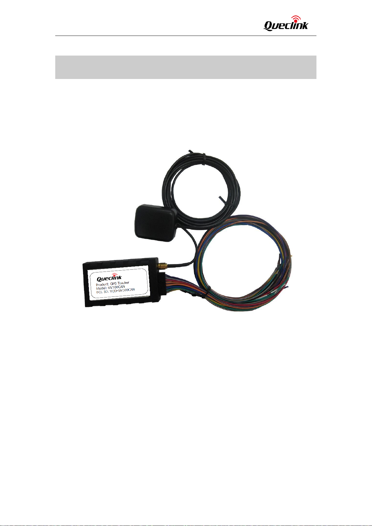
2. Product Overview
2.1. Check Parts List
Before starting, check whether all the following items have been included with your GV300CAN.
If anything is missing, please contact your supplier.
Figure 1. Appearance of GV300CAN
TRACGV300CANUM001 - 8 -
Page 9

GV300CAN User Manual
Name
Picture
GV300CAN Locator
80*49*26 mm
User Cable
GPS Antenna (Optional)
MiniUSB_DATA_CABLE_1.5M (Optional)
2.2. Parts List
Table 3. Parts List
2.3. Interface Definition
The GV300CAN has a 16 PIN interface connector which contains the connections for power, I/O,
RS232, CAN, J1708, 1-wire, etc. The sequence and definition of the 16PIN connector are shown in
the following figure:
TRACGV300CANUM001 - 9 -
Figure 2. The 16 PIN Connector on the GV300CAN
Page 10

GV300CAN User Manual
Index
Description
Comment
1
CAN_H
CAN BUS output H
2
CAN_L
CAN BUS output L
3
IGN
Ignition input, positive trigger
4
RXD
UART RXD, RS232
5
TXD
UART TXD, RS232
6
GND
Power and digital ground
7
DATA_1W
1-Wire DATA
8
OUT2
Open drain, 150 mA max
9
J1708_A
J1708 BUS output A
10
J1708_B
J1708 BUS output B
11
VIN
12
IN2
13
IN1
14
OUT1
15
VDD_1W
16
ADC_IN
Definition
Color
PIN
No
Cable
PIN
No
Color
Definition
OUT2
Yellow
8
16
Brown/White
ADC_IN
DATA_1W
Brown
7
15
Green
VDD_1W
GND
Black
6
14
Blue
OUT1
TXD
White/Black
5
13
Orange
IN1
RXD
Pink
4
12
Orange/Black
IN2
IGN
White
3
11
Red
VIN
CAN_L
Gray/Black
2
10
Purple/White
J1708_B
CAN_H
Gray
1 9 Purple
J1708_A
Table 4. Description of 16 PIN Connections
External DC power input, 8-32V
Digital input, negative trigger
Digital input, negative trigger
Open drain, 150 mA max ,with latch circuit
1-wire device power output
ADC input
2.4. GV300CAN User Cable Color
Table 5. GV300CAN User Cable Color Definition
TRACGV300CANUM001 - 10 -
Page 11

GV300CAN User Manual
3. Get Started
3.1. Open the Case
Figure 3. Open the Case
Insert the triangular-pry-opener into the gap of the case as shown above, and push the opener
up until the case is unsnapped.
3.2. Close the Case
Place the cover on the bottom in the position as shown in the figure above. Slide the cover
against the direction of the arrow until it snaps.
TRACGV300CANUM001 - 11
-
Page 12

GV300CAN User Manual
3.3. Install a SIM Card
Open the case and ensure the unit is not powered (unplug the 16Pin cable and switch the
internal battery to the OFF position). Slide the holder right to open the SIM card holder. Insert
the SIM card into the holder as shown below with the gold-colored contact area facing down.
Take care to align the cut mark. Close the SIM card holder. Close the case.
Figure 4.
3.4. Install the Internal Backup Battery
GV300CAN has an internal backup Li-ion battery.
Figure 5.
SIM Card Installation
Backup Battery Installation
TRACGV300CANUM001 - 12 -
Page 13

GV300CAN User Manual
3.5. SYNC Switch
The switch was used to Synchronize the car model. You can push the switch to the left as the
Arrow direction,and hold it approximately 3 seconds to Synchronize the car model。
Figure 6.
Note:
If device is configured for any car, synchronization can be started in the following way:
1. Make sure the CAN function is enabled before you push the SYNC switch.
2. Connect the power for the device. The CAN LED lights red.
3. Press the button on the front panel of the device (you can hold it while connecting power
supply).
4. After approximately 8 seconds, the CAN light will light green. Then release the button.
After starting the device, sync CAN light blinks red. After several seconds (up to half a minute),
synchronization is done and:
- if the green CAN light lights – car has been synchronized successfully, turn the power supply off
and on after 5 seconds - now the device is synchronized with the car.
- if the CAN light flashes alternating green / red - it means an invalid connection to the CAN-bus.
Make sure the CAN-bus wires are not swapped (CAN-H against CANL), and the ignition is turned
on. If these conditions are met – the device is not connected to any CAN-bus.
- if the red CAN light - CAN bus connection is correct, but the car has not been recognized. The
current version of the software will not work with this car model.
CAN-bus synchronization may also be performed through the serial port.
On request, the device may be delivered with the proper configuration for the selected car
model.
SYNC Switch
TRACGV300CANUM001 - 13 -
Page 14

GV300CAN User Manual
GPS antenna
Specification
Frequency
1575.42 MHz
Bandwidth
>5 MHz
Beam width
>120 deg
Supply voltage
2.7V-3.3V
Polarization
RHCP
Gain
Passive: 0 dBi min
Active: 15 dB
Impedance
50Ω
VSWR
<2
Noise figure
<3
3.6. Install the External GPS Antenna (Optional)
There is a SMA GPS antenna connector on GV300CAN. The GV300CAN will automatically detect
and use an external antenna when connected.
Figure 7.
3.6.1. GPS Antenna Specification
Table 6. GPS Antenna Specification
GPS Antenna of GV300CAN
3.7. Power Connection
VIN (PIN11)/GND (PIN6) is the power input pin. The input voltage range for this device is from 8V
to 32V. The device is designed to be installed in vehicles that operate on 12V or 24V systems
without the need for external transformers.
TRACGV300CANUM001 - 14 -
Page 15

GV300CAN User Manual
Logical status
Electrical characteristics
Active
5.0V to 32V
Inactive
0V to 3V or open
3.8. Ignition Detection
Table 7. Electrical Characteristics of Ignition Detection
Figure 8.
Typical Power Connection
TRACGV300CANUM001 - 15 -
Figure 9. Typical Ignition Detection
Page 16

GV300CAN User Manual
Logical status
Active
Inactive
IGN (Pin3) is used for ignition detection. It is strongly recommended to connect this pin to
ignition key “RUN” position as shown above.
An alternative to connecting to the ignition switch is to find a non-permanent power source that
is only available when the vehicle is running, for example, the power source for the FM radio.
IGN signal can be configured to start transmitting information to the backend server when
ignition is on, and enter the power saving mode when ignition is off.
3.9. Digital Inputs
There are two general purpose digital inputs on GV300CAN. They are all negative triggers.
Table 8. Electrical Characteristics of the Digital Inputs
Electrical characteristics
0V to 0.8V
Open
The following diagram shows the recommended connection of a digital input.
Figure 10. Typical Digital Input Connection
TRACGV300CANUM001 - 16 -
Page 17

GV300CAN User Manual
Logical status
Electrical characteristics
Enable
<1.5V @150 mA
Disable
Open drain
3.10. Analog Inputs
There are one analog input on GV300CAN, The analog input voltage range could be
selectable, Including 0-12V and 0-30V, and the default range is from 0 to 30V. The
following diagram shows the recommended connection.
Figure 11. Typical Analog Input Connection
3.11. Digital Outputs
There are two digital outputs on GV300CAN. All are of open drain type and the maximum drain
current is 150 mA. Each output has the built-in over current PTC resettable fuse.
Figure 12. Digital Output Internal Drive Circuit
TRACGV300CANUM001 - 17 -
Table 9. Electrical Characteristics of Digital Outputs
Page 18

GV300CAN User Manual
Figure 13. Typical Connection with Relay
Figure 14. Typical Connection with LED
Note:
1. OUT1 will latch the output state during reset.
2. Many modern relays come with a flyback diode pre-installed internal to the relay itself. If the
relay has this diode, ensure the relay polarity is properly connected. If this diode is not internal, it
should be added externally. A common diode such as a 1N4004 will work in most circumstances.
TRACGV300CANUM001 - 18 -
Page 19

GV300CAN User Manual
3.12. Serial Port/UART Interface
There are two lines dedicated to the Serial Port/UART interface (TXD and RXD). TXD/RXD is
standard RS232 signal.
Figure 15. Typical Connection with RS232 Port
3.13. 1-Wire device Connection
It has 1-wire bus on GV300CAN, which supports temperature sensors and iButton. The
bus includes 3 signals, namely, VDD-1W, DATA-1W and GND. VDD-1W is the power
output for 1-wire device, and DATA-1W is the data signal, with which GV300CAN can get
information from 1-wire device.
The following diagrams show the recommended connection of 1-wire device.
TRACGV300CANUM001 - 19 -
Page 20

GV300CAN User Manual
Figure 16. Typical Connection with 1-wire Device
Figure 17. Typical Connection with iButton Reader
TRACGV300CANUM001 - 20 -
Page 21

GV300CAN User Manual
Figure 18. Typical Connection with Temperature Sensor
TRACGV300CANUM001 - 21 -
Page 22

GV300CAN User Manual
3.14. Device Status LED
Table 10. Definition of Device Status and LED
LED Device status LED status
GSM
(Note 1)
GPS
(Note 2)
CAN Start the synchronization procedure. Blinking red
Device is searching GSM network. Fast flashing
(Note 3)
Device has registered to GSM network. Slow flashing
(Note 4)
SIM card needs pin code to unlock. ON
GPS chip is powered off. OFF
GPS sends no data or data format error occurs. Slow flashing
GPS chip is searching GPS info. Fast flashing
GPS chip has gotten GPS info. ON
Synchronization is complete and successfully. Lights green
Synchronization is complete. CAN-bus connected
properly, but the car is not recognized.
Invalid connection to the CAN-bus. Flashes green/red
CAN-Logistic connected successfully to vehicle’s
bus(es). (Note 5)
CAN-bus does not read CAN-bus data. (Note 5) Interval 4 seconds,
CAN-Logistic connected successfully to vehicle’s
bus(es). (Note 6)
CAN-Logistic reads only one bus(CAN or J1708)
(Note 6)
CAN-Logistic reads none bus(neither CAN nor J1708)
(Note 6)
Lights red
Interval one second,
Green LED blinks once
Green LED blinks once
Interval one second,
Green LED double
blink
Interval one second,
Green LED blinks once
Interval 4 seconds,
Green LED blinks once
TRACGV300CANUM001 - 22 -
Page 23

GV300CAN User Manual
Figure 19. GV300CAN LED on the Case
Note:
1. GSM LED cannot be configured.
2. GPS LED and PWR LED can be configured to turn off after a period of time by using the
configuration tool.
3. Fast flashing: for GSM LED is about 60 ms ON/780 ms OFF; for GPS LED and PWR LED is about
100 ms ON/100 ms OFF.
4. Slow flashing: for GSM LED is about 60 ms ON/1940 ms OFF; for GPS LED and PWR LED is
about 600 ms ON/600 ms OFF.
5. When only CAN-bus is connected.
6. When both buses (CAN i J1708) are connected.
3.15. Bluetooth
The device role of Bluetooth could be Master and Slave.
When the device role is Slave, the device will provide below services: device information
service, battery information service, virtual serial port service. Other devices can read or
use these services after connecting devices.
When the device role is Master, the device will provide below services: the others devices
can read or use the above services after connecting devices, connect the designated
device to read the data or related information of the designated Bluetooth devices. After
reading the data, the server can be reported to the server by the corresponding message.
TRACGV300CANUM001
- 23 -
Page 24

GV300CAN User Manual
3.15.1. Bluetooth usage
Install Lightblue APP on your smartphone for IOS, and install NRF Connect for Android.
command:
Send
“AT+GTBTS=gv300can,1,,GV300CAN_BT,7,3,666,1D07,0003,0,123456,,,,,,,,,,,,FFFF$”
by Manage Tool to device to turn on Bluetooth. The device will connect to smartphone.
Send command
“AT+GTBTS=gv300can,0,,GV300CAN_BT,7,3,666,1D07,0003,0,123456,,,,,,,,,,,,FFFF$”
by Manage Tool to device to turn off Bluetooth. The device will disconnect to smartphone.
FCC Statement
Any Changes or modifications not expressly approved by the party responsible for compliance could void
the user’s authority to operate the equipment.
This device complies with part 15 of the FCC Rules. Operation is subject to the following two conditions:
(1) This device may not cause harmful interference, and
(2) This device must accept any interference received, including interference that may cause undesired
operation.
FCC Radiation Exposure Statement:
This equipment complies with FCC radiation exposure limit
environment .This equipment should be installed and operated with minimum distance 20cm between
the radiator& your body.
s set forth for an uncontrolled
TRACGV300CANUM001 - 24 -
 Loading...