

Page 1
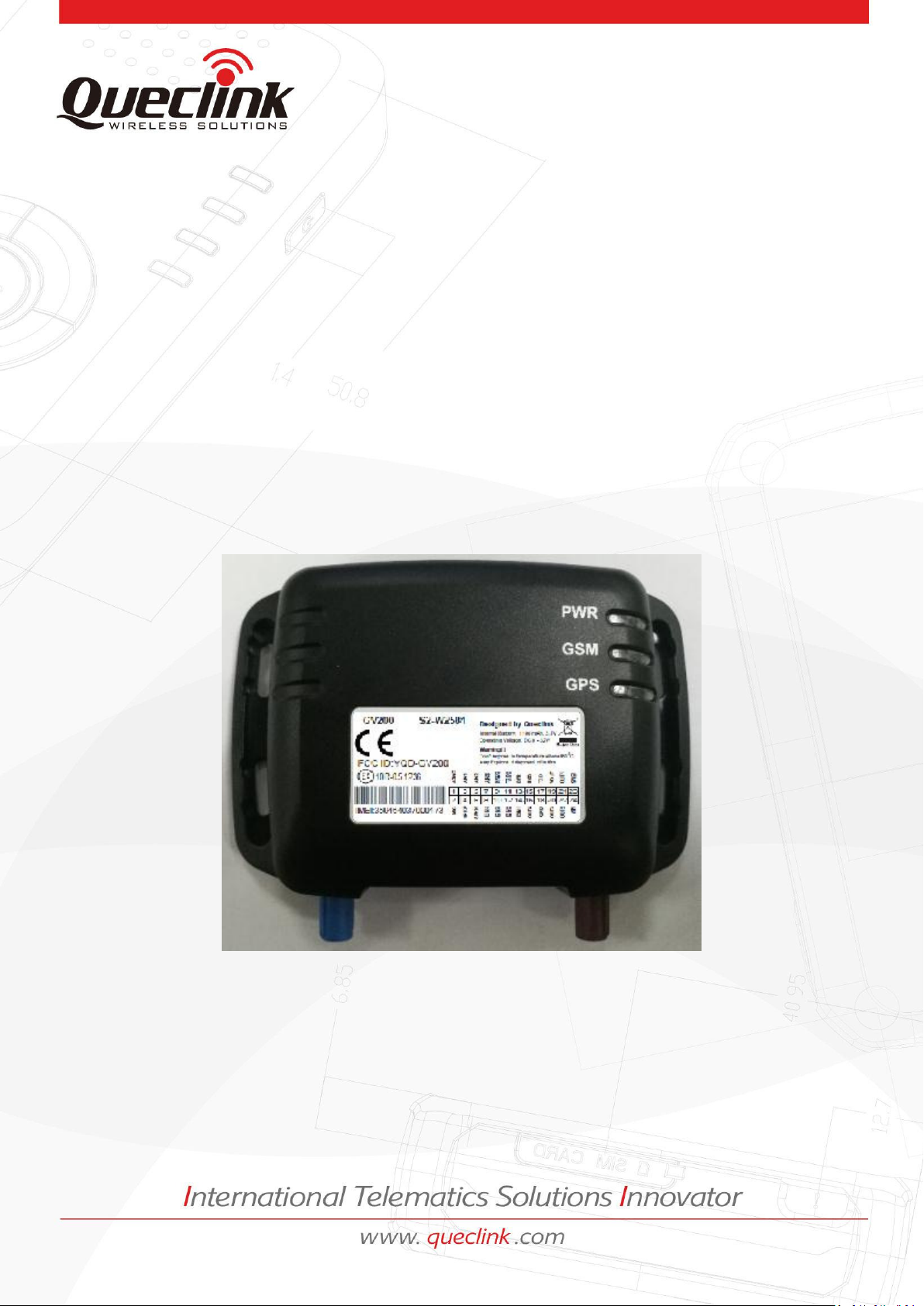
GV200 User Manual
GPRS/GPS Tracker
TRACGV200UM001
Version:R1.01
Page 2

GV200 User Manual
Document Title
GV200 User Manual
Version
1.01
Date
2015-10-21
Status
Release
Document Control ID
TRACGV200UM001
General Notes
Queclink offers this information as a service to its customers, to support application and
engineering efforts that use the products designed by Queclink. The information provided is
based upon requirements specifically provided to Queclink by the customers. Queclink has
not undertaken any independent search for additional relevant information, including any
iforatio that ay e i the ustoer’s possessio. Furtherore, syste validatio of
this product designed by Queclink within a larger electronic system remains the
responsibility of the custoer or the ustoer’s syste itegrator. All speifiatios
supplied herein are subject to change.
Copyright
This document contains proprietary technical information which is the property of Queclink
Wireless Solutions Co., Ltd.The copying of this document and giving it to others and the
using or communication of the contents thereof, are forbidden without express authority.
Offenders are liable to the payment of damages. All rights reserved in the event of grant of a
patent or the registration of a utility model or design. All specification supplied herein are
subject to change without notice at any time.
TRACGV200UM001 - 1 -
Page 3

GV200 User Manual
Contents
Contents ............................................................................................................................................ 2
Table Index ........................................................................................................................................ 3
Figure Index ....................................................................................................................................... 4
0. Revision History ............................................................................................................................. 5
1. Introduction .................................................................................................................................. 6
1.1. Reference............................................................................................................................. 6
1.2. Terms and Abbreviations ..................................................................................................... 6
2. Product Overview .......................................................................................................................... 7
2.1. Appearance ......................................................................................................................... 7
2.2. Parts List .............................................................................................................................. 8
3. Interface Description ..................................................................................................................... 9
3.1. SIM Card Interface ............................................................................................................... 9
3.2. Antenna Interface .............................................................................................................. 10
3.2.1. Install Antennas ............................................................................................... 10
3.2.2. GPS antenna specification ............................................................................... 10
3.2.3. GSM antenna specification.............................................................................. 11
3.3. User Interface .................................................................................................................... 12
3.3.1. Interface Definition ......................................................................................... 12
3.3.2. Power Connection ........................................................................................... 13
3.3.3. 5V Output ........................................................................................................ 14
3.3.4. Reset Key ......................................................................................................... 14
3.3.5. Ignition Detect ................................................................................................. 14
3.3.6. Ignition Control................................................................................................ 15
3.3.7. Electrical conditions for digital inputs ............................................................. 16
3.3.8. Digital Input without Interrupt ........................................................................ 17
3.3.9. Digital Input with Interrupt ............................................................................. 18
3.3.10. Analog Input .................................................................................................... 18
3.3.11. Digital Output .................................................................................................. 20
3.4. Indicator Light Description ................................................................................................ 22
TRACGV200UM001 - 2 -
Page 4

GV200 User Manual
Table Index
TABLE 1: REFERENCE ......................................................................................................................... 6
TABLE 2: TERMS AND ABBREVIATIONS .............................................................................................. 6
TABLE 3: PART LIST ............................................................................................................................ 8
TABLE 4: GPS ANTENNA SPECIFICATION ......................................................................................... 10
TABLE 5: GSM ANTENNA SPECIFICATION ........................................................................................ 11
TABLE 6: THE DEFINITION OF 24 PIN CONNECTOR ......................................................................... 12
TABLE 7: THE DESCRIPTION OF 24 PIN ............................................................................................ 13
TABLE 8: ELECTRICAL CONDITIONS OF IGNITION DETECT ............................................................... 15
TABLE 9: ELECTRICAL CONDITIONS OF IGNITION CONTROL ........................................................... 15
TABLE 10: ELECTRICAL CONDITIONS OF NEGATIVE TRIGGER DIGITAL INPUTS................................ 16
TABLE 11: ELECTRICAL CONDITIONS OF POSITIVE TRIGGER DIGITAL INPUTS ................................. 17
TABLE 12: ELECTRICAL CONDITIONS OF DIGITAL OUTPUTS ............................................................ 20
TABLE 13: DESCRIPTION OF LEDS .................................................................................................... 23
TRACGV200UM001 - 3 -
Page 5

GV200 User Manual
Figure Index
FIGURE 1: APPEARANCE OF GV200 .................................................................................................. 7
FIGURE 2: SIM CARD INTERFACE ...................................................................................................... 9
FIGURE 3: SIM CARD INSTALLATION ................................................................................................ 9
FIGURE 4: THE ANTENNAS OF GV200 ............................................................................................ 10
FIGURE 5: THE SEQUENCE OF 24 PIN CONNECTOR ........................................................................ 12
FIGURE 6: EXAMPLE OF POWER CONNECTION ............................................................................. 14
FIGURE 7: THE KEY OF RESET .......................................................................................................... 14
FIGURE 8: IGNITION DETECTION .................................................................................................... 15
FIGURE 9: EXAMPLE CONNECTION OF IGNITION CONTROL .......................................................... 16
FIGURE 10: EXAMPLE CONNECTION FOR NEGATIVE TRIGGER DIGITAL INPUTS ........................... 17
FIGURE 11: EXAMPLE CONNECTION FOR POSITIVE TRIGGER DIGITAL INPUTS ............................ 17
FIGURE 12: EXAMPLE CONNECTION OF PANIC BUTTON ............................................................... 18
FIGURE 13: AIN1 CONNECT TO NTC RESISTOR ............................................................................... 19
FIGURE 14: AIN2/3 CONNECT TO CAPACITANCE-TYPE SENSOR ..................................................... 19
FIGURE 15: THE EXAMPLE CONNECTION TO DRIVE A LED ............................................................ 20
FIGURE 16: THE EXAMPLE CONNECTION TO DRIVE A RELAY ........................................................ 21
FIGURE 17: LEDS ON GV200 ........................................................................................................... 22
TRACGV200UM001 - 4 -
Page 6

GV200 User Manual
Revision
Date
Author
Description of change
1.00
2015-10-14
Richard Deng
Initial
1.01
2015-10-21
Bingo Huang
1. Page 10,The GPS Power Supply Voltage
is 3V ,not 3.3V
2.
Add Diode Description of the Relay
driver
, Page 17,figure 9 和 Page 22 figure
16.
0. Revision History
TRACGV200UM001 - 5 -
Page 7

GV200 User Manual
SN
Document name
Remark
[1]
GV200 @Track Air Interface Protocol
The air protocol interface between
GV200 and backend server.
Abbreviation
Description
AGND
Analog Ground
AIN
Analog Input
DIN
Digital Input
DOUT
Digital Output
GND
Ground
MIC
Microphone
RXD
Receive Data
TXD
Transmit Data
SPKN
Speaker Negative
SPKP
Speaker Positive
1. Introduction
The GV200 is a powerful GPS Locator designed for vehicle tracking or asserts tracking. With
superior receiving sensitivity, fast TTFF (Time to First Fix) and Dual-Band GSM frequencies
850/1900, its location can be monitored in real time or periodically tracked by a backend
server or other specified terminals. The GV200 has multiple input/output interfaces which
can be used for monitoring or controlling external devices. Based on the integrated @Track
protocol, the GV200 can communicate with a backend server through the GPRS
network to transfer reports of Emergency, Geo-fence boundary crossings, Lower Battery or
scheduled GPS position along with many other useful functions. Users can also use GV200 to
monitor the status of a vehicle and control the vehicle with its external relay output. System
Integrators can easily setup their tracking systems based on the full-featured @Track
protocol.
1.1 Reference
Table 1: Reference
1.2 Terms and Abbreviations
Table 2: Terms and abbreviations
TRACGV200UM001 - 6 -
Page 8
GV200 User Manual
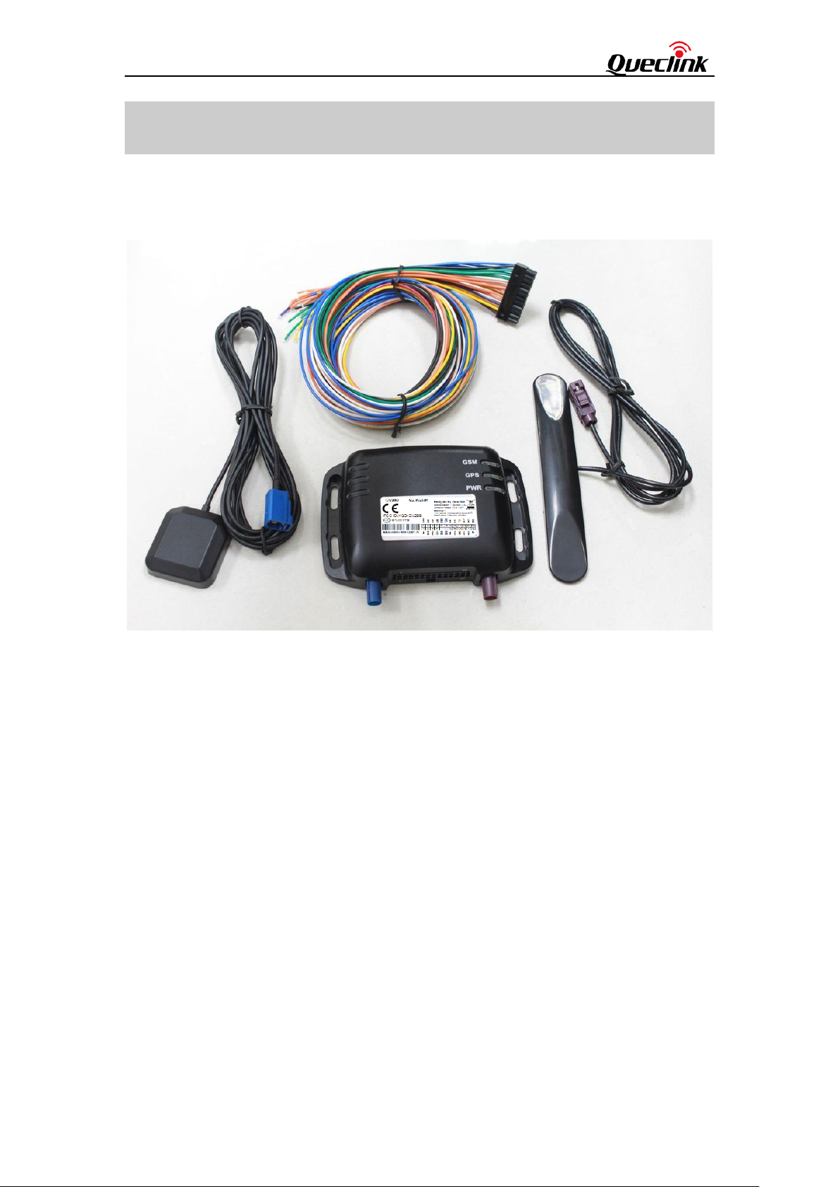
2. Product Overview
2.1 Appearance
Figure 1: Appearance of GV200
TRACGV200UM001 - 7 -
Page 9

GV200 User Manual
Name
Picture
GV200 Locater
User Cable
GPS Antenna
GSM Antenna
12V DC power supply (Optional)
USB-232 data cable (Optional)
Uart Cable (Optional)
Extend Cable (Optional)
2.2 Parts List
Table 3: Part List
TRACGV200UM001 - 8 -
Page 10

GV200 User Manual
3. Interface Description
3.1 SIM Card Interface
To install the SIM card
Step 1: Press the yellow button on the right side of SIM card slot to eject the SIM card
holder.
Figure 2: SIM Card Interface
Step 2: Put the SIM card on the SIM card holder.
Step 3: Install the SIM card holder to SIM card slot. Please pay attention to the direction.
Figure 3: SIM Card Installation
TRACGV200UM001 - 9 -
Page 11

GV200 User Manual
GPS antenna:
Frequency: 1575.42MHz
Bandwidth:
>5MHz
Beamwidth:
>120 deg
Supply voltage:
3V
Polarization:
RHCP
Gain:
Internal antenna: 0dBi
External antenna: 15dB
Impedance:
Ω
VSWR:
﹤2
Noise figure:
﹤3
3.2 Antenna Interface
3.2.1 Install Antennas
There are two Fakra antenna connectors on GV200, the blue one for GPS and the purple one
for GSM. Please find the GPS antenna and GSM antenna in package box. Install them to the
correct Fakra connector as following.
Figure 4: The Antennas of GV200
3.2.2 GPS antenna specification
Table 4: GPS antenna specification
TRACGV200UM001 - 10 -
Page 12

GV200 User Manual
GSM antenna specification
Frequency and bandwidth
GSM850: 824MHz to 894MHz
PCS1900: 1850MHz to 1990MHz
Direction:
Omnidirection
Gain:
Passive: >0dBi
Impedance:
Ω
VSWR:
<4
Efficient:
GSM850: >40%
PCS1900: >30%
3.2.3 GSM antenna specification
Table 5: GSM antenna specification
TRACGV200UM001 - 11 -
Page 13

GV200 User Manual
1 3 5 7 9
11
13
15
17
19
21
23
AGND
AIN1
AIN2
AIN3
RXD2
TXD2
DTR
RXD
TXD
VOUT
DOUT1
GND
2 4 6 8 10
12
14
16
18
20
22
24
MIC
SPKP
SPKN
DIN4
DIN3
DIN2
DIN1
DOUT4
GND
DOUT3
DOUT2
VIN
3.3 User Interface
3.3.1 Interface Definition
There is a 24 PIN connector on GV200. It contains the interface of power, I/O, RS232,
microphone, speaker, etc. The sequence and definition of the 24 PIN connector are showed
in following figure:
Figure 5: The sequence of 24 PIN connector
Table 6: The definition of 24 PIN connector
TRACGV200UM001 - 12 -
Page 14

GV200 User Manual
Index
Color of User
cable
Description
Comment
1
Black
Analog Ground
For microphone and analog inputs
2
Blue
Microphone Input
MIC+
3
Green
Analog Input 1
(Input range: 0 ~
2.7V)
For resistance-type sensors
4
Blue
Speaker Output
Differential, Positive
5
Green
Analog Input 2
For capacitance-type sensors
6
Blue
Speaker Output
Differential, Negative
7
Green
Analog Input 3
For capacitance-type or resistance-type
sensors
8
White
Digital Input 4
Negative Trigger
9
Orange
Receive Data
(UART2, RS232)
Connect to TXD of external device
10
White
Digital Input 3
Positive Trigger, With interrupt
11
Orange/Gray
Transmit Data
(UART2, RS232)
Connect to RXD of external device
12
White
Digital Input 2
Negative Trigger, with interrupt.
Recommended for panic button
13
Orange/Brown
DTR
Data Terminal Ready.
For waking up UART1 & UART2
14
White
Digital Input 1
(ACC Detect)
Positive Trigger, fixed for ignition detect
15
Orange
Receive Data
(UART1, RS232)
Connect to TXD of external device
16
Yellow
Digital Output 4
Negative Trigger
17
Orange/Gray
Transmit Data
(UART1, RS232)
Connect to RXD of external device
18
Black
Ground
For 5V output and UART
19
Purple
5V Output
VOUT
20
Yellow
Digital Output 3
Negative Trigger
21
Yellow
Digital Output 1
Negative Trigger
22
Yellow
Digital Output 2
Negative Trigger
23
Black
Ground
Power Ground
24
Red
Power (VIN)
Table 7: The description of 24 PIN
3.3.2 Power Connection
PIN 24 is named as VIN which input voltage range is 12V or 24V DC and can be connected to
vehile’s attery diretly V or V DC.
TRACGV200UM001 - 13 -
Power
Page 15

GV200 User Manual
Please install the power like following.
Figure 6: Example of power connection
3.3.3 5V Output
PIN 19 is named as VOUT which can drive a controlled 5V output for user. Please note that if
user wants to drive a 5V output, GV200 must be supplied by external power. In default, 5V
output is disabled, user can use AT commend to enabled 5V output. The max drive current
of VOUT is 0.25A.
3.3.4 Reset Key
There is a reset key on the right side of SIM Card interface. When the key is pressed, the
device will reboot. Please note that reboot do not change any firmware parameter.
Figure 7: The key of reset
3.3.5 Ignition Detect
The PIN 14 is DIN1 (Positive trigger). Its electrical conditions are:
TRACGV200UM001 - 14 -
Page 16

GV200 User Manual
Logical State
Electrical State
Active
12V/24V
Inactive
0V to 3V or Open
Table 8: Electrical conditions of ignition detect
It is strongly recommended to connect this pin to ignition key to support the power saving
function when the vehicle is off.
Figure 8: Ignition detection
Another easy way is to connect PIN14 to a power output in the fuse box of the vehicle which
is only enabled after the vehicle is ignition on. For example: the power output for radio FM.
3.3.6 Ignition Control
DOUT1/2/3/4 can be used to control ignition key. They are Open-Drain type with no internal
pull-up resistor which also be used to control a relay. It means that the user has to connect a
pull-up resistor or a relay coil between the DOUT1/2/3/4 pin and any positive voltage to
generate a correct output. The DOUT1/2/3/4 pin can drive a continuous current of 0.2A.
The electrical conditions of it are:
Table 9: Electrical conditions of ignition control
TRACGV200UM001 - 15 -
Page 17

GV200 User Manual
Logical State
Electrical State
Enable
<1.5V, drive current is 0.2A
Disable
Open or the pull-up voltage
Logical State
Electrical State
Active
0V to 0.8V
Inactive
1.7V to 32V or Open
User can use this pin to control a relay output. An example to control the ignition key is
showed in following figure. Please refer to chapter 3.3.11 for the detail information on how
to drive a relay with digital output.
Figure 9: Example connection of ignition control
3.3.7 Electrical conditions for digital inputs
For negative trigger inputs the electrical conditions are:
Table 10: Electrical conditions of negative trigger digital inputs
The example connection is showed as follow:
TRACGV200UM001 - 16 -
Page 18

GV200 User Manual
Logical State
Electrical State
Active
5.0V to 32V
Inactive
0V to 3V or Open
Figure 10: Example connection for negative Trigger digital inputs
For positive trigger inputs the electrical conditions are:
Table 11: Electrical conditions of positive trigger digital inputs
The example connection is showed as follow:
Figure 11: Example connection for positive trigger digital inputs
3.3.8 Digital Input without Interrupt
The DIN1 and DIN4 are digital inputs which do not have interrupt. DIN1 is positive trigger
and DIN4 is negative trigger. The sample rate for this digital input is 2 to 24 seconds. Please
note the high sample rate will also result in high power consumption.
TRACGV200UM001 - 17 -
Page 19

GV200 User Manual
3.3.9 Digital Input with Interrupt
DIN2 and DIN3 are digital inputs which have interrupt. DIN2 is negative trigger and DIN3 is
positive trigger.
The example connections are same as showed in chapter 3.3.7.
DIN2 is also recommended to support panic button function and the connection is showed
as follow.
Figure 12: Example connection of panic button
3.3.10 Analog Input
The PIN 3/5/7 are used for analog to digital converter. GV200 can support different type
sensors such as resistance-type and capacitance-type due to the differences between the
three analog inputs. Please note it is an average value based on the sample rate from 2 to 24
seconds, which means the burst on voltage input may not be detected.
3.3.10.1 Resistance-type Sensor
AIN1 (PIN 3) is designed to support some resistance-type sensors and there is an internal
pull-up resistor (100K Ohm) on its channel. Due to the internal pull-up resistor, user can
connect resistance-type sensors directly between analog inputs and AGND. The follow figure
is the example connection of AIN1 with NTC resistor. The recommended value of NTC
resistor is 100K@25℃.
TRACGV200UM001 - 18 -
Page 20

GV200 User Manual
Figure 13: AIN1 connect to NTC resistor
3.3.10.2 Capacitance-type Sensor
AIN2 (PIN 5) and AIN3 (PIN 7) are designed to support capacitance-type sensors. In default
GV200 only support capacitance-type sensors which voltage range is 0 ~ 2.7V. If user wants
to use the capacitance-type sensors which voltage range is out of 0 ~ 2.7V, a level transfer
board must be used between capacitance-type sensors and GV200. The follow figure is the
example connection of AIN2/3 with capacitance-type sensors.
Figure 14: AIN2/3 connect to capacitance-type sensor
User also can connect a power source directly to AIN2/3, the voltage limitation is same as
capacitance-type sensor.
TRACGV200UM001 - 19 -
Page 21

GV200 User Manual
Logical State
Electrical State
Enable
<1.5V, drive current is 0.2A
Disable
Open or the pull-up voltage
3.3.11 Digital Output
The outputs are Open-Drain type with no internal pull-up resistor which also be used to
control a relay. It means that the user has to connect a pull-up resistor or a relay coil
between the output pin and any positive voltage to generate a correct output. Each output
can drive a continuous current of 0.2A.
The electrical conditions are:
Table 12: Electrical conditions of digital outputs
Digital outputs are used for cutting/restoring GND. The example connections are:
Figure 15: The example connection to drive a LED
TRACGV200UM001 - 20 -
Page 22

GV200 User Manual
Figure 16: The example connection to drive a relay
Note: All outputs are internally pulled up to PWR pin by a diode. So no external flyback diode
is needed when the output is connected to an inductive load.
If the digital output is used to drive a relay, a catch diode is showed across the relay coil, this
is necessary to prevent damage to the digital output when the relay is turned off. Many
modern relays come with this diode pre-installed internal to the relay itself. If the relay has
this diode, insure the proper relay polarity connected is used. If this diode is not internal, it
should be added externally. A common diode such as a 1N4004 will work in most
circumstances.
TRACGV200UM001 - 21 -
Page 23

GV200 User Manual
3.4 Indicator Light Description
Figure 17: LEDs on GV200
There are three LEDs in GV200, the description as follow.
TRACGV200UM001 - 22 -
Page 24

GV200 User Manual
Light
Case
State
GPS LED
If LED switch is set to off by AT+GTCFG, GPS LED will
be off all the time after it has worked for 30
minutes maximum from GV200 was powered on. In
this case, cases for GPS LED listed below will be
ignored.
Always Off
GPS LED will be off if GPS chip is closed.
Off
Checksum of NEMA packet from GPS chip is invalid.
Slow flashing
There is no data output from GPS chip when it is
working.
GPS chip is trying to get valid GPS info.
Fast flashing
GPS chip has been getting valid GPS info.
On
PWR LED
If LED switch is set to off by AT+GTCFG, PWR LED
will be off all the time after it has worked for 30
minutes maximum from GV200 was powered on. In
this case, cases for PWR LED listed below will be
ignored.
Always Off
Backup battery is enabled and its voltage is not low
if external power supply is cut.
Off
Backup battery is enabled and its voltage is low if
external power supply is cut.
Slow flashing
Backup battery is enabled and it is in charging by
external power supply.
Fast flashing
Backup battery is enabled and it is fully charged by
external power supply.
On
Backup battery is disabled and external power
supply is connected.
GSM LED
GV200 is in searching GSM network state.
Fast flashing
GV200 has been registered to GSM network.
Slow flashing
SIM card inserted to GV200 need pin code to
unlock.
On
Table 13: Description of LEDs
TRACGV200UM001 - 23 -
Page 25

FCCWarning:
Any Changes or modifications not expressly approved by the party responsible for compliance could void the
user’s authority to operate the equipment.
This device complies with part 15 of the FCC Rules. Operation is subject to the following two conditions: (1) This
device may not cause harmful interference, and (2) this device must accept any interference received, including
interference that may cause undesired operation.
FCC Radiation Exposure Statement:
This equipment complies with FCC radiation exposure limits set forth for an uncontrolled environment .This
equipment should be installed and operated with minimum distance 20cm between the radiator& your body.
This transmitter must not be co-located or operating in conjunction with any other antenna or transmitter.
 Loading...