

Page 1

GMT100 User manual
GPRS/GPS Tracker GMT100
User Manual
TRACGMT100UM001
Revision: 1.04
TRACGMT100UM001 -10-
sales@queclink.com
http://www.queclink.com
Page 2

GMT100 User Manual
Document Title
Version
Date
Status
Document Control ID
GMT100 User Manual
1.04
2015-10-08
Release
TRACGMT100UM001
General Notes
Queclink offers this information as a service to its customers, to support application and
engineering efforts that use the products designed by Queclink. The information provided
is based upon requirements specifically provided to Queclink by the customers. Queclink
has not undertaken any indep endent search for additional relevant information, including
any information that may be in the customer’s possession. Furthermore, system validation
of this product designed by Q ueclink within a larger electronic system remains th e
responsibility of the customer or the customer’s system in tegrator. All specifications
supplied herein are subject to change.
Copyright
This document contains proprietary technical information which is the property of Queclink
Wireless Solutions Co., Ltd. copying of this document and giving it to others and the using
or communi cation of the contents thereof, are forbidde n without expr ess authority.
Offenders are liable to the payment of damages. All rights reserved in the event of grant of
a patent or the registration of a utility model or design. All specification supplied herein are
subject to change without notice at any time.
TRACGMT100UM001 - 2 -
Page 3

GMT100 User Manual
Contents
1. Introduction ................................................................................................................... 7
1.1. Reference ............................................................................................................. 7
1.2. Terms and Abbreviations ...................................................................................... 7
2. Product Overview .......................................................................................................... 8
2.1. Appearance .......................................................................................................... 8
2.2. Parts List ............................................................................................................... 9
2.3. Interface Definition ................................................................................................ 9
3. Getting Started ............................................................................................................ 10
3.1. Installing a SIM Card .......................................................................................... 10
3.2. Switch the set on/off ........................................................................................... 10
3.3. Reset Key ............................................................................................................ 11
3.4. USB connector ..................................................................................................... 11
3.5. Power Connection ............................................................................................... 11
3.6. Ignition Detection ................................................................................................. 11
3.7. Digital Input ......................................................................................................... 12
3.8. Analog Input........................................................................................................ 13
3.. Relay Output ..................................................................................................... 14
3.1. Device Status LED ............................................................................................ 15
TRACGMT100UM001 - 3 -
Page 4

GMT100 User Manual
TableIndex
Table 1 : GMT100 Protocol Reference .............................................................................. 7
Table 2 : Terms and Abbreviations .................................................................................... 7
Table 3 : Part List .............................................................................................................. 9
Table 4 : Description of GMT100 User Cable .................................................................... 9
Table 5 : Electrical Characteristics of Ignition Detection .................................................. 12
Table 6 : Electrical Characteristics of the digital inputs .................................................... 12
Table 7 : Definition of Device status and LED ......................................... 16
TRACGMT100UM001 - 4 -
Page 5

GMT100 User Manual
FigureIndex
Figure 1. Appearance of GMT100 ..................................................................................... 8
Figure 2. SIM Card Installation ........................................................................................ 10
Figure 3. Typical Power Connection ................................................................................. 11
Figure 4. Typical Ignition Detection ................................................................................. 12
Figure 5. Typical Digital Input Connection ....................................................................... 13
Figure 6. Typical Analog Input Connection ...................................................................... 13
Figure 7. Typical Connection with Siren .......................................................................... 14
Figure 8. GMT100 LED on the Case ............................................................................... 15
TRACGMT100UM001 - 5 -
Page 6

GMT100 User Manual
Revision History
Revision Date Author Description of change
V1.00 2011-11-12 Lei Initial
V1.01 2012-09-29 Lei 1> Replace the picture on the cover
2> Add the de scription and notices of cut
relay output in chapter of 3.10
3> Modify the description of t able 7 in
chapter of 3.9
4> Update the description of some figures
V1.02 2013-9-16 Owen change the relay from NO(normal open to
NC(Normal close)
V1.03 2013-02-20 Super change the current an d volt age v alues of
relay outpu t from 30A&16V to 20 А&
12V
V1.04 2015-10-08 Super change the Figure 8(add the diode) and
add The relay diode attention description
TRACGMT100UM001 - 6 -
Page 7

GMT100 User Manual
1. Introduction
The GMT10 0 is a powe rful GPS locator designe d for vehicle or asset tracking. It has
superior receiver sensitivity , fast TTFF (Time to First Fix) and
frequencies 850/1900, its location can be monitored in real time or be periodically tracked
by a backend server or other s pecified terminals. The GMT100 has multiple input/outpu t
interfaces that can be us ed for monitoring or controlling external devices. Based on th e
integrated @Track protocol, the GMT100 ca n communicate with a backend server
through the GPRS network to tr ansfer reports of Emergency, geo-fence boundary
crossings, lo w backup battery or scheduled GPS position as well as many other useful
functions. Users can also use GM T100 to monitor the status of a vehicle and control the
vehicle by its external relay output. System Integrators can easily s etup their trackin g
systems based on the full-featured @Track protocol.
supports Quad-Band GSM
1.1. Reference
Table 1: GMT100 Protocol Reference
SN Document name Remark
[1] GMT100 @Track Air Interface Protocol The air protocol interface between
GMT100 and backend server.
1.2. Terms and Abbreviations
Table 2: Terms and Abbreviations
Abbreviation Description
AIN Analog Input
DIN Digital Input
DOUT Digital Output
GND Ground
TRACGMT100UM001 -10-
Page 8

GMT100 User Manual
2. Product Overview
2.1. Appearance
Figure 1. Appearance of GMT100
TRACGMT100UM001 -10-
Page 9
GMT100 User Manual
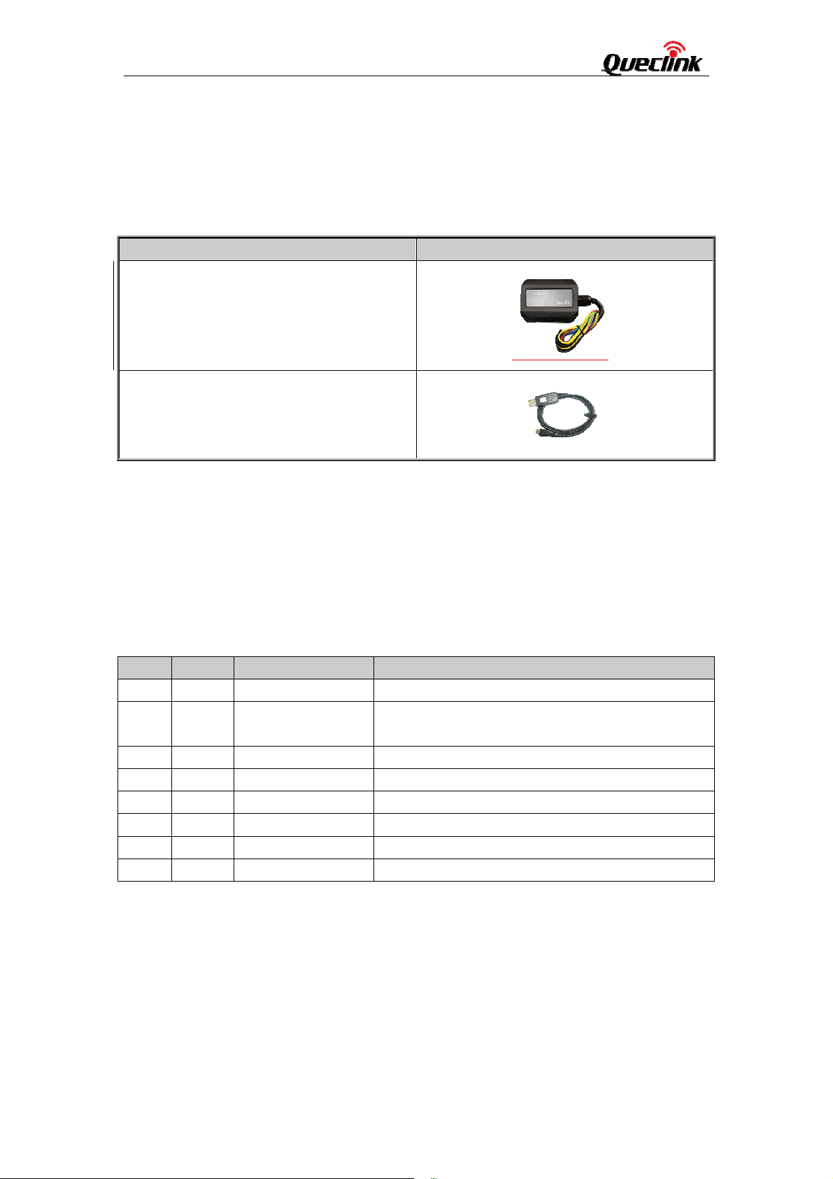
2.2. Parts List
Table 3: Part List
Name Picture
GMT100 Locator
DATA_CABLE_M (Optional)
2.3. Interface Definition
There are 8 wires on GMT100 User Cable which contain the connection for power, ignition
input, digital input, analog input, siren output, cut output etc. The user cable’s definition is
shown in following table.
Table 4: Description of GMT100 User Cable
Index Colour Description Comment
1 Red Power
2 Black
3 White Ignition Ignition input, positive trigger
4 Blue Digital input Digital input, negative trigger
5 Green Analog input
6 Brown Siren output Siren output, high end
7 Yellow Relay output line1 Internal relay output line1.
8 Yellow Relay output line2 Internal relay output line2
Ground
External DC power input, 12/24V
System ground
(connect to the vehicle’s frame directly)
Analog input, 12/24V
TRACGMT100UM001 - 9 -
Page 10

GMT100 User Manual
3. Getting Started
3.1. Installing a SIM Card
Step 1: Remove the cover by screwdriver.
Step 2: Make sure the contact area is facing down, insert the SIM into the slot.
Step 3: Install the SIM card cover.
Figure 2. SIM Card In
stallation
3.2. Switch the set on/off
There are two methods to Power on GMT100:
- GMT100 external power turned on.
- Connect GMT100 to PC with user cable.
When the external power or USB cable power be removed,GMT100 will switch to internal
backup battery and keep on running. When internal backup battery is exhausted, GMT100
will give a report and then turn off.
Note:
1-External power and User USB power can be present at same time.
2-For USB port current limitation, w hen configuring GMT100 by user cable, please let
backup battery on using.
There is one method to turn off GMT100.
TRACGMT100UM001 -10-
Page 11

GMT100 User Manual
-Remove the external power and USB power.
-Press the reset key.
Note:
GMT100 PWR LED will off.
3.3. Reset Key
There is a reset key behind the SIM card cover. If the power wire is connected to vehicle
power, the system will reboot when the key is pressed; if the system is powered by the
backup battery and th e power wire is not be c onnected to vehi cle power, the system will
shutdown when the key is pressed.
Note:
When you finished the firmware upgrade, please press the reset key to reboot the system
before configuring the terminal.
3.4. USB connector
There is a USB connector on GMT100 which is beside the SIM card. With the USB
connector a nd the DAT A_CABLE_M, user ca n configure the syste m or downl oad
firmware. As long as the DATA_CABLE_M is plugged in, the system will boot.
3.5. Power Connection
The red wire is power wire and the black wire is ground wire. The input voltage range for
this device is from 12 to 24V. The device is designed to be installed in vehicles that
operate on 12V or 24V systems without the need for external transformers.
Figure 3. T
ypical Power Connection
3.6. Ignition Detection
TRACGMT100UM001 -12 -
Page 12

GMT100 User Manual
Table 5: Electrical Characteristics of Ignition Detection
Logical State Electrical State
Active
12/24V
Inactive 0V to 3V or Open
Figure 4. Ty
pical Ignition Detection
The white wire is u sed for ignition detection. It is str ongly reco mmended to connect this
wire to ignition key “RUN” position as shown up.
An alternative to connecting to the ignition switch is to find a non permanent power source
that is only a vailable when the vehicle is running. For exam ple the pow er source for the
FM radio.
Ignition signal can be co nfigured to start transmitting information to backend server whe n
ignition is on; and enter power saving mode when ignition is off.
3.7. Digital Input
There is a g eneral purpose digital input whic h is the blue wire on GMT100 User Cable,
and it is a negative trigg er. The digital input is r ecommended to support panic button
function.
Table 6: Electrical Characteristics of the digital inputs
Logical State Electrical Characteristics
Active 0V to 0.8V
Inactive Open
The following diagram sh
TRACGMT100UM001 -12 -
ows the recommended connection of the digital input.
Page 13

GMT100 User Manual
Figure 5. Typical Digital Input Connection
3.8. Analog Input
There is an analog input which is the green wire on GMT100 User Cable, and the analog
input voltage range is 12/24V. The following diagram shows the recommended
connection.
Figure 6. Ty
pical Analog Input Connection
TRACGMT100UM001 -12 -
Page 14

GMT100 User Manual
3.. Relay Output
There is a built-in cut relay on GMT1 00, and it is a NC(Normal Close) type relay w hich
maximum switching voltage is 12VDC an d ma ximum continuous curre nt is 20A. On
GMT100 user cable one 18AWG yellow wire is connected to the relay NC contact and the
other 18AWG yellow wire is connected to the relay COM contact. In certain instances the
two wires will be connected together.
Note:
1: The rela y output can b e latched by the software, so even if the GMT10 0 is restart or
power down in some cases, the relay output will not change. To use the latch function the
main power and backup battery should be connec ted. Otherwise the relay will be always
in normal close status.
2: The relay works only with 12V main powe r. Use it when the main pow er is 24V may
result in damaging.
Many modern relays come with a flyback diode pre-installed internal to the relay itself. If
3:
the relay has this diode, ensure the relay polarity is properly connected. If this diode is not
internal, it should be added externall y. A common diode such as a 1N4004 will work in
most circumstances.
Figure 7. Typical Connection with Relay
TRACGMT100UM001 -12 -
Page 15

GMT100 User Manual
3.1. Device Status LED
Figure 8. GMT100 LED on the Case
TRACGMT100UM001 -12 -
Page 16

GMT100 User Manual
Table : Definition of Device status and LED
LED Device status LED status
GSM
(note1)
Device is searching GSM network Fast flashing
(Note3)
Device has registered to GSM network. Slow flashing
(Note4)
SIM card needs pin code to unlock. ON
GPS
(note 2)
GPS chip is powered off OFF
GPS sends no data or data format error. Slow flashing
GPS chip is searching GPS info. Fast flashing
GPS chip has gotten GPS info. ON
PWR
(note 2)
No exter nal power and b ackup battery volt age is
lower than 3.35V.
No exter nal power and b ackup battery volt age is
OFF
Slow flashing
below 3.5V.
External power in and backup battery is charging Fast flashing
External po wer in and backup ba ttery is fully
ON
charged
Note:
1 - GSM LED cannot be configured.
2 - GPS LED and PWR LED can be configured to turn off after a period of time using the
configuration tool
3 - Fast flashing is about 60ms ON/ 780ms OFF
4 - Slow flashing is about 60ms ON/ 1940ms OFF
TRACGMT100UM001 -12 -
Page 17

GMT100 User Manual
FCC Warning:
Any Changes or modifications not expressly approved by the party responsible for compliance could
void the user's authority to operate the equipment.
This device complies with part 15 of the FCC Rules. Operation is subject to the following two
conditions: (1) This de
any interference received, including interference that may cause undesired operation.
vice may not cause
harmful interference, and (2) this device must accept
FCC Radiation Exposure Statement:
This equipment complies with FCC radiation exposure limits set forth for an uncontrolled
environment .This equipment should be installed and operated with minimum distance 20cm
between the radiator& your body.
This transmitter must not be co-lo cated or operating in conjunction with any oth er antenna or
transmitter.
TRACGMT100UM001 -12 -
 Loading...