

Page 1
GPS Tracker
GB100MG Lite User Manual
TRACGB100MGLSUM001
Version:R1.00
GB100MG Lite
Page 2

GB100MG Lite User Manual
Document Title
Version
Date
Status
Document Control ID
GB100MG Lite user manual
1.00
2019-12-04
Young.Chen
TRACGB100MGLSUM001
General Notes
Queclink offers this information as a service to its customers, to support application and
engineering efforts that use the products designed by Queclink. The information provided
is based upon requirements specifically provided to Queclink by the customers. Queclink
has not undertaken any independent search for additional relevant information, including
any information that may be in the customer’s possession. Furthermore, system validation
of this product designed by Queclink within a larger electronic system remains the
responsibility of the customer or the customer’s system integrator. All specifications
supplied herein are subject to change.
Copyright
This document contains proprietary technical information which is the property of Queclink
Limited., copying of this document and giving it to others and the using or communication
of the contents thereof, are forbidden without express authority. Offenders are liable to the
payment of damages. All rights reserved in the event of grant of a patent or the
registration of a utility model or design. All specification supplied herein are subject to
change without notice at any time.
TRACGB100MGLSUM001 - 1 -
Page 3

GB100MG Lite User Manual
Contents
0. Revision History ....................................................................................................................... 5
1. Introduction ................................................................................................................................... 6
1.1. Reference ............................................................................................................................. 6
2. Product Overview ......................................................................................................................... 7
2.1. Check Part List .................................................................................................................... 7
2.2. Part List ............................................................................................................................... 8
2.3. Interface Definition ............................................................................................................. 8
3. Getting Started .............................................................................................................................. 9
3.1. Opening the Case ................................................................................................................ 9
3.2. Closing the case ................................................................................................................. 10
3.3. Installing SIM card ............................................................................................................ 11
3.4. Power Connection ............................................................................................................. 12
3.5. LED Status ........................................................................................................................ 13
3.6. Motion Sensor Direc tion ................................................................................................... 14
4. GB100MG Lite Certification ...................................................................................................... 15
TRACGB100MGLSUM001 - 2 -
Page 4

GB100MG Lite User Manual
Table Index
TABLE 1. GB100MG LITE PROTOCOL REFERENCE ........................................................................ 6
TABLE 2.PART LIST ............................................................................................................................ 8
TABLE 3.DESCRIPTION OF 2 PIN POWER CABLE ....................................................................... 8
TABLE 4.DEFINITION OF DEVICE ST ATUS AND LED ............................................................... 13
TRACGB100MGLSUM001 - 3 -
Page 5

GB100MG Lite User Manual
Figure Index
FIGURE 1. APPEARANCE OF GB100MG LITE .................................................................................. 7
FIGURE 2. GB100MG LITE 2 PIN POWER CABLE ............................................................................ 8
FIGURE 3. OPENING THE CASE ......................................................................................................... 9
FIGURE 4. CLOSING THE CASE ........................................................................................................ 10
FIGURE 5. INSTALLING SIM CARD ................................................................................................. 11
FIGURE 6. TYPICAL POWER CONNECTION .................................................................................. 12
FIGURE 7. GB100MG LITE LED ON THE CASE .............................................................................. 13
FIGURE 8. MOTION SENSOR DIRECTION .............................................................................................. 14
TRACGB100MGLSUM001 - 4 -
Page 6

GB100MG User Manual
0. Revision History
Revision Date Author Description of change
1.00 2019-12-04 Young.Chen Initial
TRACGB100MGSUM001
- 5
Page 7

GB100MG User Manual
SN
Document name
Remark
1. Introduction
The GB100MG Lite is a device designed for self-installation by a customer. It simply
mounts directly onto the vehicle’s battery with only two wires to attach. This approach
allows for either a very low cost installation or for the insurance customer to self-install. Its
built-in GNSS receiver has very high sensitivity, a fast time to first fix and supports 10 Hz
location sampling during vehicle motion. Their multiband LTE Cat-M1 and Cat-NB1 allow
the GB100MG Lite location to be monitored in real time or periodically tracked by a
backend server and mobile devices. Its built-in 3-axis accelerometer allows motion
detection, 100 Hz* pre/post incident data collection. System integration is straightforward
as complete documentation is provided for the full featured @Track protocol. The @Track
protocol supports a wide variety of reports including emergency, geo-fence boundary
crossings, and scheduled and compressed GPS position.
1.1. Reference
Table 1. GB100MG lite Protocol Reference
[1] GB100MGL @Tracker Air Interface Protocol The air protocol interface between
GB100MG Lite and backend
server.
TRACGB100MGSUM001
- 6
Page 8

GB100MG User Manual
2. Product Overview
2.1. Check Part List
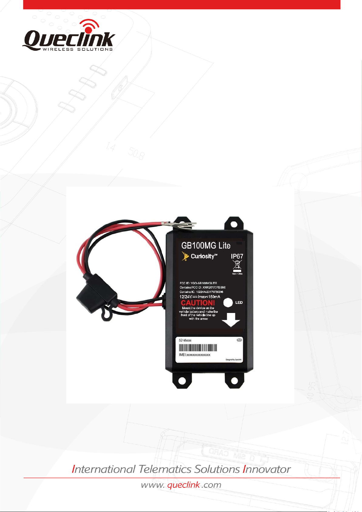
Before starting, check all the following items have been included with your GB100MG Lite.
If anything is missing, please contact your supplier.
Figure 1. Appearance of GB100MG Lite
TRACGB100MGSUM001
- 7
Page 9

GB100MG User Manual
Index
Description
Comment
1
VIN
Extend DC power input,8-32V
2
GND
GND
2.2. Part List
Table 2.Part list
Name Picture
GB100MG Lite Locator
2.3. Interface Definition
The GB100MG Lite has a 2 PIN power cable. The pin definition of the 2 pin power cable
as below:
Figure 2. GB100MG Lite 2 Pin power cable
TRACGB100MGLSUM001 - 8 -
Table 3.Description of 2 PIN Power Cable
Page 10

GB100MG User Manual
1 2 3 4 5
3. Getting Started
3.1. Opening the Case
Take out the 6pcs screws from the device and push the opener up until the case
unsnapped.
re 3. Opening the case
Figu
TRACGB100MGSUM001
- 9 -
Page 11

GB100MG User Manual
1 2 3
4
3.2. Closing the case
1st, make sure the silicon rubber seal ring is in the gap of front case.
2nd, put the power cable wire holder in the rubber groove of rear case.
3rd, place the cover on the bottom in the position as shown in the following figure.
Then, press the cover until it snapped (press the LTE antenna side firstly as the arrow
shows).
4th, tighten the screws.
Figu
re 4. Closing the case
TRACGB100MGLSUM001 - 10 -
Page 12
GB100MG User Manual
5
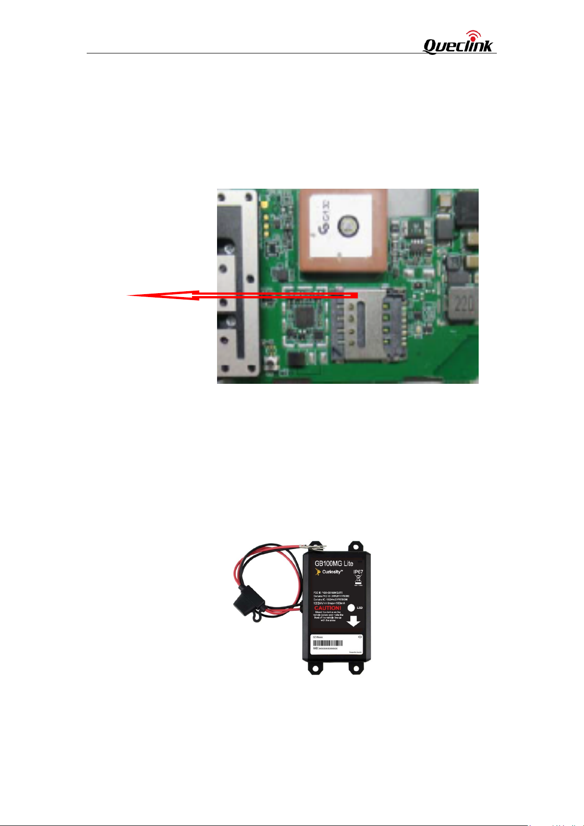
3.3. Installing SIM card
open the case and ensure the unit is not powered. and slide the holder left to open the
SIM card holder. put the SIM card on the holder as shown below with the gold-colored
contact area facing down taking care to align the cut mark. slide the holder right to close
the SIM card holder. close the case.
SIM Card
Figure 5. Installing SIM card
TRACGB100MGLSUM001 - 11 -
Page 13

GB100MG User Manual
3.4. Power Connection
PWR (PIN1) / GND (PIN2) are the power input pins. The input voltage range for this
device is from 8V to 32V. The device is designed to be installed in vehicles that operate on
12V/24V vehicle without the need for external transformers.
Figure
6. Typical Power Connection
Note:
1. Do not connect any external cable on GB100MG Lite device.
2. The GB100MG Lite is simply mounts directly onto the vehicle's battery with only two
wires to attach. It must more than 20cm from the human body.
TRACGB100MGLSUM001 - 12 -
Page 14

GB100MG User Manual
LED Device status
LED status
flashing: 100ms On, 500ms Off,
Three flashing: 100ms On, 500ms off,
100ms On, 500ms Off, 100ms On, 2s off..
e flashing: 100ms
100ms On,
500ms off, 100ms On, 500ms off, 100ms
Queclink
3.5. LED Status
LED
Table 4.Definition of Device status and LED
Working Normally Continuous on
PDP not activated One flashing: 100ms On, 2s 0f
Network not registered or SIM card not inserted Two
100ms On, 2s Off...
GNSS not fixed
PDP not activated and GNSS not fixed
Network not registered or SIM card not inserted and
GNSS not fixed
Device power off or sleep mode Extinguished
One flashing + Thre
On, 2s off, 100ms On, 500ms off, 100ms
On, 500ms off, 100ms On, 2s off...
Two flashing + Three flashing: 100ms On,
500ms Off, 100ms On, 2s Off
On, 2s off...
Fig
TRACGB100MGLSUM001 - 13 -
ure 7. GB100MG Lite LED on the case
Page 15

GB100MG User Manual
3.6. Motion Sensor Direction
GB100MG Lite has an internal 3-axis accelerometer supporting driving behavior
monitoring and motion detection. The following shows the direction of the motion sensor.
The Z axis faces outwards vertically.
Figure 8. Motion Sensor Direction
TRACGB100MGLSUM001 - 14 -
Page 16

GB100MG User Manual
FCC Waring:
Any Changes or modifications not expressly approved by
the party responsible
for
compliance could avoid the user’s authority to operate the equipment.open
This device complies with part 15 of the FCC
Rules. Operation
following two conditions: (1) This device may not cause harmful interference, and (2)
device must accept
any interference received, including interference that may cause
is subject to the
this
undesired operation.
FCC Radiation Exposure Statement:
This equipment complies with FCC radiation exposure limits set forth for an uncontrolled
environment .This equipment should be installed and operated with minimum distance 20cm
between the radiator& your body.
Note: This equipment has been tested and found to comply with the limits for a Class B digital
device, pursuant to part 15 of the FCC Rules. These limits are designed to provide reasonable
protection against harmful interference in a residential installation. This equipment generates,
uses and can radiate radio frequency energy and, if not installed and used in accordance with
the instructions, may cause harmful interference to radio communications. However, there is
no guarantee that interference will not occur in a particular installation. If this equipment does
cause harmful interference to radio or television reception, which can be determined by
turning the equipment off and on, the user is encouraged to try to correct the interference by
one or more of the following measures:cor
—Reorient or relocate the receiving antenna.
—Increase the separation between the equipment and receiver.
—Connect the equipment into an outlet on a circuit different from that to which the receiver is
connected.
—Consult the dealer or an experienced radio/TV technician for help.
TRACGB100MGLSUM001 - 15 -
 Loading...