

Quattroflow QF1200, QF150, QF4400, QF20K, QF5050 Installation, Operation And Troubleshooting Instructions
Page 1
Quattroflow
Installation,
Operation &
Troubleshooting
Version: Rev. 0 (July 2017)
Guide
Page 2

Quattroflow Installation, Operation & Troubleshooting Guide
Rev. 0
INDEX
1 Introduction .................................................................................................................................................. 4
2 Basics ............................................................................................................................................................. 5
2.1 General description of Quattroflow Pumps & Functioning .................................................................. 5
2.2 Volume flow and pressure .................................................................................................................... 6
3 Medium ......................................................................................................................................................... 7
3.1 Chemical resistance .............................................................................................................................. 7
3.2 Solids and suspensions .......................................................................................................................... 8
3.3 Sticky Mediums ..................................................................................................................................... 8
3.4 Medium with high viscosity .................................................................................................................. 9
4 Installation .................................................................................................................................................. 10
4.1 Suction line .......................................................................................................................................... 10
4.2 Outlet line ........................................................................................................................................... 10
4.3 Protection from high pressure ............................................................................................................ 10
4.4 High inlet pressure .............................................................................................................................. 10
4.5 Flow directions .................................................................................................................................... 11
4.6 Product connections ........................................................................................................................... 11
5 Start-up operations ..................................................................................................................................... 12
5.1 Mounting the pump ............................................................................................................................ 12
5.2 Mounting the pump chamber ............................................................................................................. 12
5.3 Cleaning before start-up (Multiple-Use, Stainless Steel pump chamber) .......................................... 12
5.4 Priming ................................................................................................................................................ 13
6 Cleaning ....................................................................................................................................................... 14
6.1 CIP – Cleaning in place ........................................................................................................................ 14
6.2 SIP - Steaming in place ........................................................................................................................ 17
6.3 Autoclave ............................................................................................................................................ 18
7 Drainability of Quattroflow Pumps ............................................................................................................. 19
7.1 Optimized drainability: orientation of the pump chamber ................................................................ 19
7.2 Full drainability: Vertical position of the pump (pump chamber downwards) .................................. 21
8 Troubleshooting .......................................................................................................................................... 23
Page 2 of 25 www.quattroflow.com
Page 3

Quattroflow Installation, Operation & Troubleshooting Guide
Revision
Date
Changes/ Comment
Issued by
0
July 2017
First Release
Tim Dudda
Rev. 0
Page 3 of 25 www.quattroflow.com
Page 4

Quattroflow Installation, Operation & Troubleshooting Guide
Rev. 0
1 INTRODUCTION
This installation, operation and troubleshooting guide helps to support the engineering / planning process,
installation and use of Quattroflow Diaphragm Pumps.
This document contains basic knowledge how Quattroflow Pumps work and explanations regarding the
technical and physical principals. It should help to project the right Quattroflow Pump for each application
and it gives important points for consideration for planned systems.
For end users we bring together topics like installation, operation and maintenance. We want to ensure a
safe and reliable operation with our pumps. The Troubleshooting section helps with quick recommendations
on identification and solving of potential issues.
Please read the official and recent operating manuals and safety instructions carefully which
are available for Quattroflow Pumps and accessories. This document doesn’t replace the user
manual.
In this guide given information are general recommendations which depend on the respective
application and process conditions.
Page 4 of 25 www.quattroflow.com
Page 5
Quattroflow Installation, Operation & Troubleshooting Guide
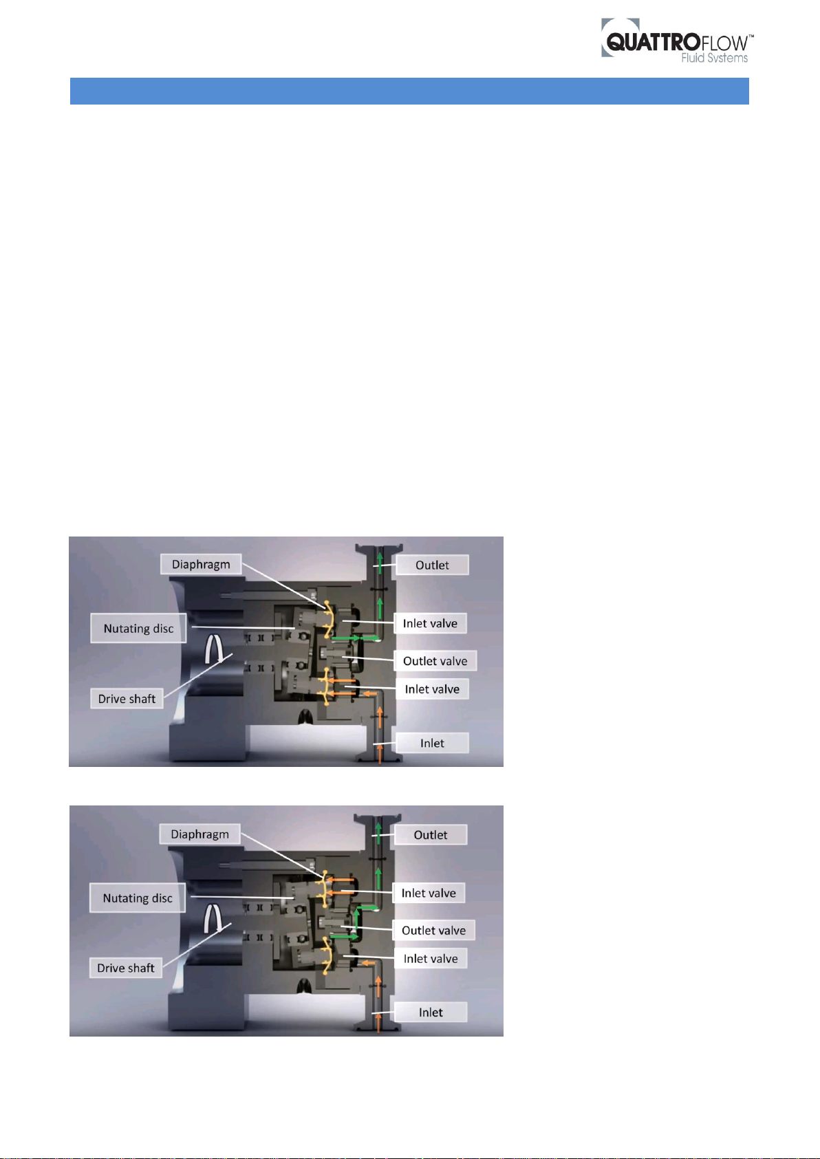
Figure 1 Sectional drawing of the Quattroflow pump head
Figure 2 Sectional drawing of the Quattroflow pump head
Rev. 0
2 BASICS
2.1 General description of Quattroflow Pumps & Functioning
Quattroflow™ develops and manufactures single-use and multiple-use Quaternary (Four-Piston) Diaphragm
Pumps for critical applications in the biopharmaceutical industry. This technology is CIP/SIP capable and
offers disposable solutions that increase flexibility, reduce down-time, eliminate costs of cleaning validation,
and risks of cross-contamination. Quattroflow pumps can be found in all areas of biologic manufacturing such
as cross-flow filtration systems, chromatography, and centrifuges. Quattroflow ensures safety, efficiency and
reliability for handling biologics such as plasma products, therapeutic proteins, monoclonal antibodies,
vaccines, and other high value products.
Technical definition:
Reciprocating positive displacement pumps
Diaphragm pump (membrane pump)
The Quattroflow displacement pump is based on this principle. The 4-piston (quaternary) diaphragm
technology enables a gentle pumping. Each stroke of the four diaphragms is generated by an eccentric shaft,
which is connected to the electric motor.
The four segments of the pump diaphragm oscillate back and forth. This alternate movement is created by a
connector plate (nutating disc) that is arranged on a ball bearing. The ball bearing sits on an eccentric shaft.
The connector plate does not turn.
The inlet and outlet check valves restrict fluid motion to the desired direction from the inlet connection port
to the outlet connection port.
Page 5 of 25 www.quattroflow.com
Page 6
Quattroflow Installation, Operation & Troubleshooting Guide
0,0
20,0
40,0
60,0
80,0
100,0
120,0
140,0
160,0
180,0
200,0
0 500 1000 1500 2000 2500 3000 3500
Flow rate [L/h]
Pump speed [rpm]
0 bar 2 bar 4 bar 6 bar
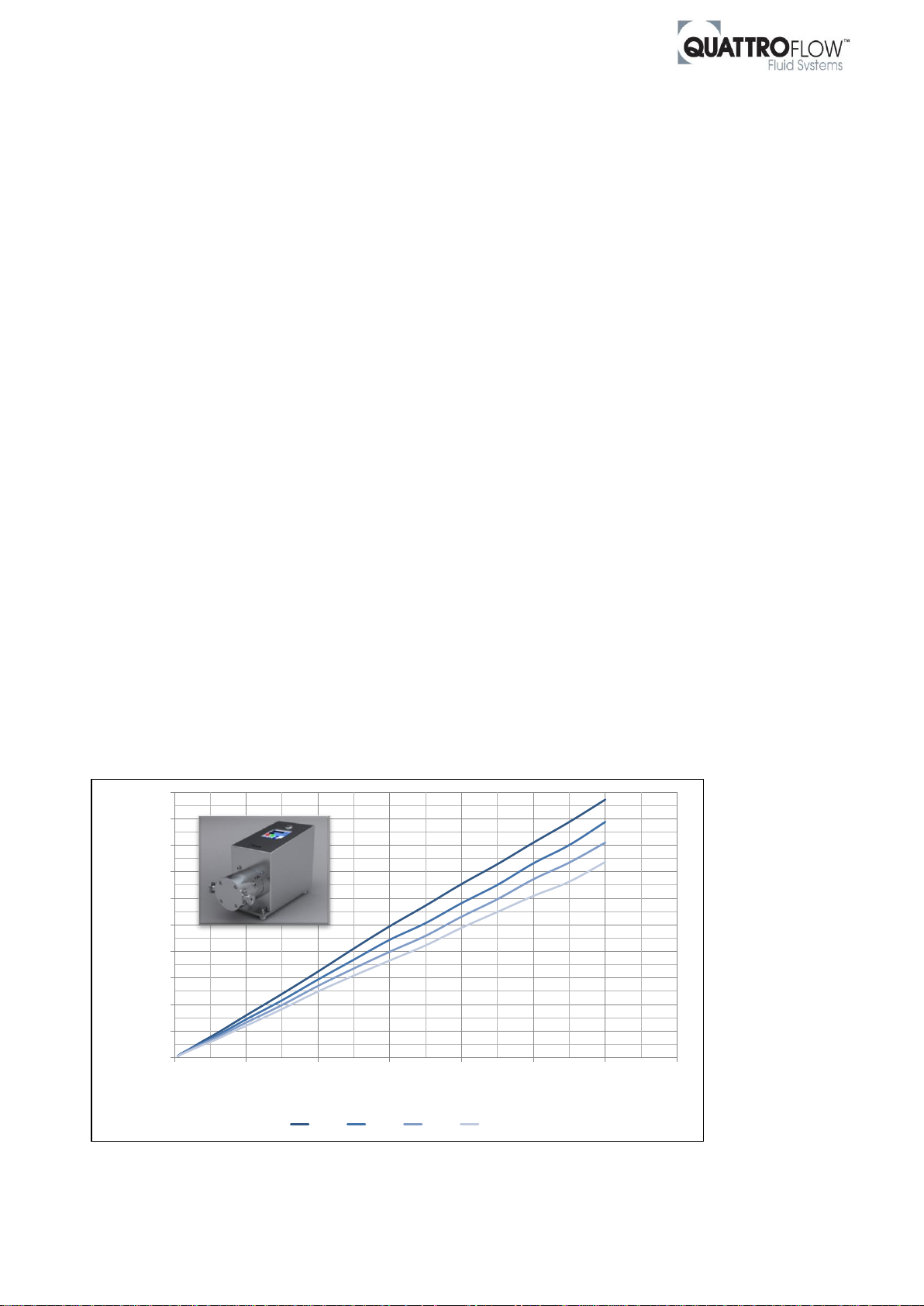
Figure 3 Exemplary pump curve for QF150 pump with 5° eccentric shaft
Rev. 0
With each turn of the eccentric shaft creates 4 discharge strokes of liquid. The overlapping of the 4 strokes
effectively minimizes the pulsation and enables stable flow conditions.
Quattroflow Pumps have got the following main features:
- Low pulsation
- Safe for dry run
- Self priming
- Linear turndown
- Low heat input
2.2 Volume flow and pressure
In opposite to other pump types like centrifugal pumps, positive displacement pumps have got a defined
displacement volume. For that reason Quattroflow Pumps have got a pump curve which is nearly linear over
the complete flow range. The pump curve shows the correlation between flow rate and discharge pressure.
The pump speed is directly related to the flow rate.
The following factors influence the correlation between pump speed and flow rate:
Back pressure
Medium (density and viscosity)
Eccentric shaft of the Pump (in degree)
Back pressure:
The higher the back pressure in your system the lower is the max. flow rate at same pump speed (see Figure
3).
Medium (density and viscosity):
All shown Quattroflow pump curves are valid for water at room temperature that means a density of approx.
1000 kg/m³ and a dynamic viscosity of approx. 1 mPa*s (= 1 cP).
The higher density and / or the viscosity the lower is the max. flow rate of the pump. Please see also chapter
“Medium with high viscosity”.
Page 6 of 25 www.quattroflow.com
Page 7
Quattroflow Installation, Operation & Troubleshooting Guide
Component
Description
Material
Certification
Diaphragm
Santoprene
USP Cl. VI, FDA 21CFR177, BSE/TSE safe
(included)
Ports,
valve plate,
pump
housing
Multiple-Use:
1.4435 / 316L
3.1 Material certificate
Ferrite and surface roughness protocol
(optional)
Single-Use:
PP / PE
USP Cl. VI, FDA 21CFR177, BSE/TSE safe
(included)
In- & outlet
valve
EPDM
USP Cl. VI, FDA 21CFR177, BSE/TSE safe
(included)
O-rings
EPDM
USP Cl. VI, FDA 21CFR177, BSE/TSE safe
(included)
Rev. 0
3 MEDIUM
3.1 Chemical resistance
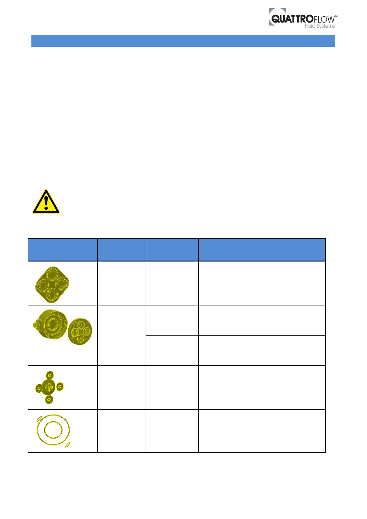
The table below shows the standard product wetted materials for multiple-use and single-use Quattroflow
pump chambers. The second table shows an overview of the chemical resistance against some mediums
which are often used with Quattroflow Pumps.
For multiple-use pump chambers made of stainless steel standard stainless steel is 1.4435 (316L). Generally
this material has got good characteristics to resist corrosion. Certainly there is a risk of pitting and surface
corrosion when the medium comes in contact with chloride-containing mediums like NaCl. On request we
could offer other stainless steel alloys with higher corrosion resistance. In this case please contact the
Quattroflow Team to get more information and support.
The chemical resistance depends on some factors like mixture, concentration, temperature and standing
time. In case that the chemical resistance is unknown we recommend to test our materials with your medium
under real conditions. Please consult the factory for support.
Please check the chemical resistance of the product wetted materials against our mediums.
If you are not sure about the chemical resistance please contact the Quattroflow Support
Team.
Table 1 Product wetted components of Quattroflow Pumps
Page 7 of 25 www.quattroflow.com
Page 8

Quattroflow Installation, Operation & Troubleshooting Guide
Substance
Santoprene
EPDM
1.4435
PP
Isopropanol,
Ethanol
Good
Good
Good
Good
NaOH
Good
Good
Good
Good
Mineral Oil
Not
recommended
Not
recommended
Good
Good
(room temperature)
NaCl
Good
Good
Not
recommended
Good
Acetic Acid
Good
Not
recommended
Good
Good
Phosphoric
Acid
Good
Good
(max 30%)
Good
Good
Toluol
Good
Not
recommended
Good
Not recommended
HCl
(max. 20%)
Good
Good
Not
recommended
Good
Acetonitrile
(diluted)
Good
Fair
Good
Not recommended
Rev. 0
Table 2 Chemical resistance of some selected mediums
3.2 Solids and suspensions
Solid particles should not have a diameter greater than 0.1mm, as larger solids can prevent valves from
proper sealing. This however depends also on the solid concentration and low concentration of larger
particles might be acceptable. Even though the pump is not damaged by particulates, care should be taken
when pumping abrasive solids. In this case please consult the factory for further support.
3.3 Sticky Mediums
In case sticky mediums are pumped, please make sure that the pump is flushed and cleaned thoroughly
immediately after the process to prevent sticking of valves.
Page 8 of 25 www.quattroflow.com
Please note that this table is for indication only and needs to be verified with the actual
medium in the process.
Page 9
Quattroflow Installation, Operation & Troubleshooting Guide
Pump size /
eccentric shaft
Max. flow rate
@ 500 mPa*s (cP)
Max. flow rate
@ 1000 mPa*s (cP)
QF150 / 5°
120 l/h
50 l/h
QF1200 / 5°
700 l/h
500 l/h
QF4400 / QF5050 / 6°
4000 l/h
3500 l/h
Rev. 0
3.4 Medium with high viscosity
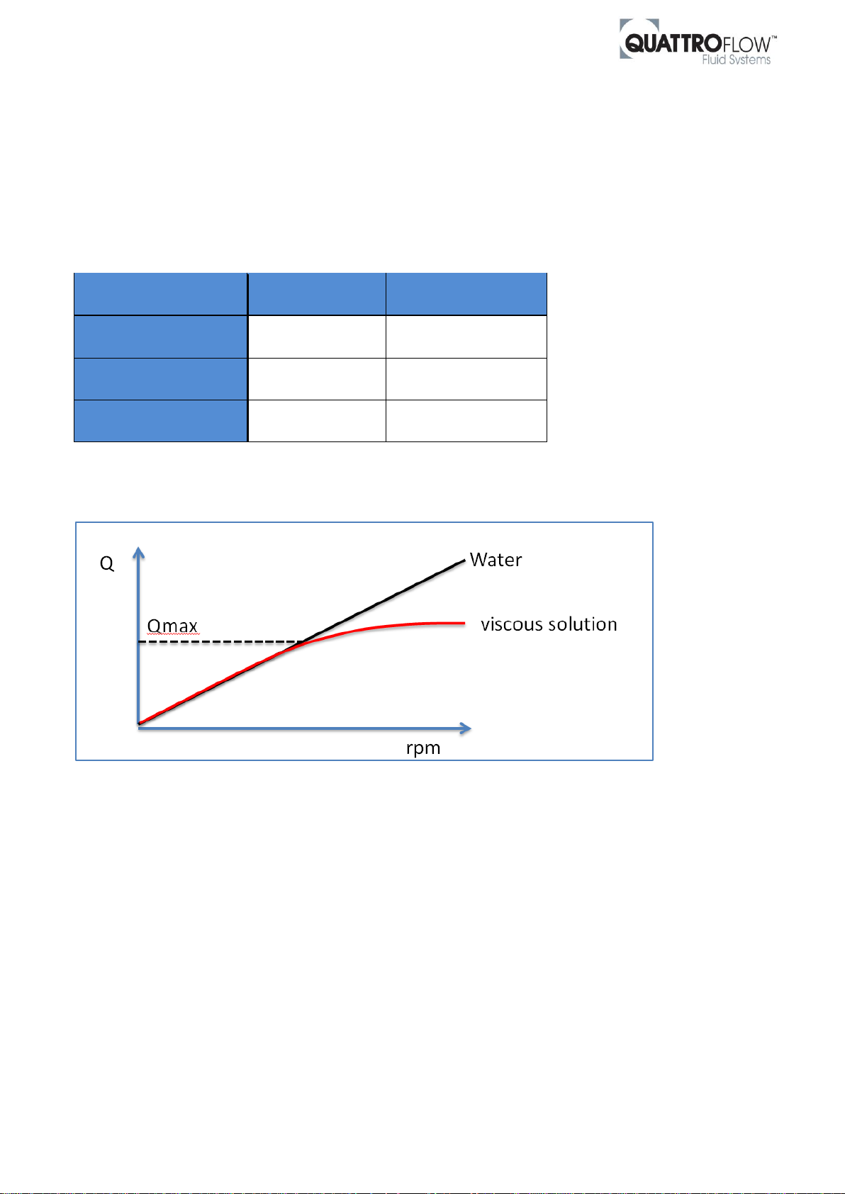
Generally Quattroflow pumps can handle medium viscosities up to 1000 mPa*s (cP). The higher the viscosity
of the medium the lower is the maximum reachable flow rate of the pump (see Table 3 below).
Please make sure that the pump is always operated in the linear range of the performance curve (see Figure
4). If the pump is operated at higher motor speeds outside the linear flow range, damage of diaphragms may
occur.
Table 3 Max. flow rates at different dynamic viscosities for different Quattroflow Pumps.
Figure 4: Max. flow rate for viscous media (exemplary)
Page 9 of 25 www.quattroflow.com
Page 10
Quattroflow Installation, Operation & Troubleshooting Guide
PSH
M
1.
2.
3.
4.
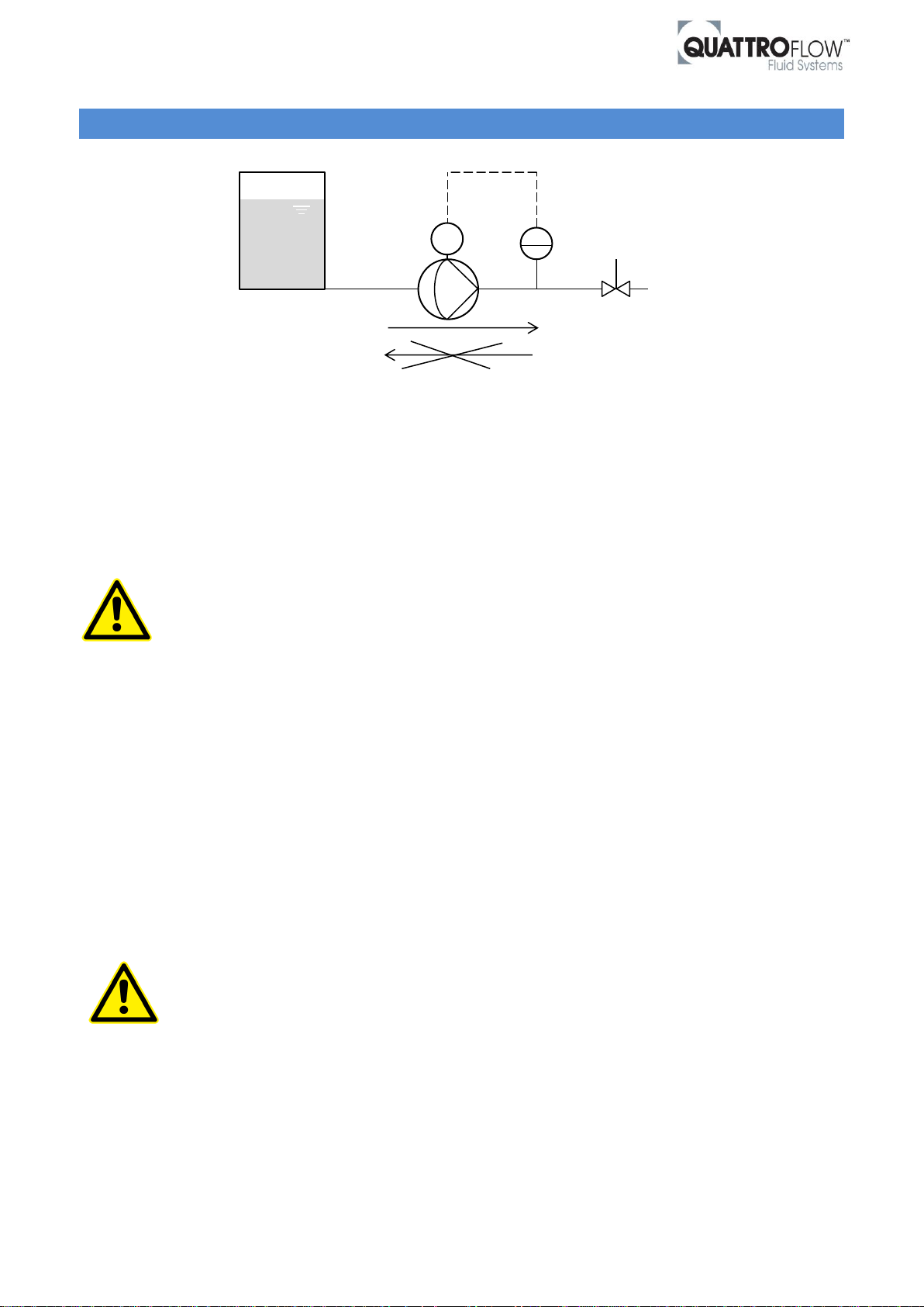
Figure 5 Exemplary set up for a Quattroflow pump.
Rev. 0
4 INSTALLATION
1.: Suction line
2.: Protection from
High pressure
3.: Outlet line
4.: Flow direction
4.1 Suction line
Make sure that the internal diameter from the suction line is large enough (typically equivalent with the
internal diameter form the pump connector). Flow velocities should typically be below 2 m/s. Consider larger
diameters for fluids with higher viscosities. Minimize the pressure drop in the suction line that can be caused
by e.g. complex valve installations, sensors, etc. Avoid high suction lift.
If hoses were used in the suction line, make sure that they do not collapse due to the negative pressure.
If these points are not considered, cavitation might occur which can result in heavily reduced
maximum achievable flow rate, strong pulsation, heavy noise and potentially damage of the
pump!
4.2 Outlet line
Please make sure that the outlet line is large enough (typically equivalent with the internal diameter form the
pump connector). If the inner diameter of the outlet line is too small, the pump performance is limited.
Make sure that the outlet pipe or hose is safe against high pressure.
4.3 Protection from high pressure
In order to protect the diaphragm from high pressure events (e.g. accidentally closed valves) we strongly
recommend installing either a pressure relief valve or a pressure switch in the outlet line that automatically
turns of the motor in case the maximum allowed pressure has been reached. Consider the technical
specification from the pump for the maximum allowed pressure.
A short too high back pressure can cause damage at the diaphragms. For this reason it is very
important to protect the pump from high pressure on the pressure line.
4.4 High inlet pressure
In case of high inlet pressure (e.g. due to high filling level of the feeding vessel) we recommend to install a
pressure reducing valve on the discharge side of the pump in case low flow rates need to be achieved. This is
necessary, because the fluid path through the pump is open in flow direction.
Page 10 of 25 www.quattroflow.com
Page 11
Quattroflow Installation, Operation & Troubleshooting Guide
QF150
QF1200
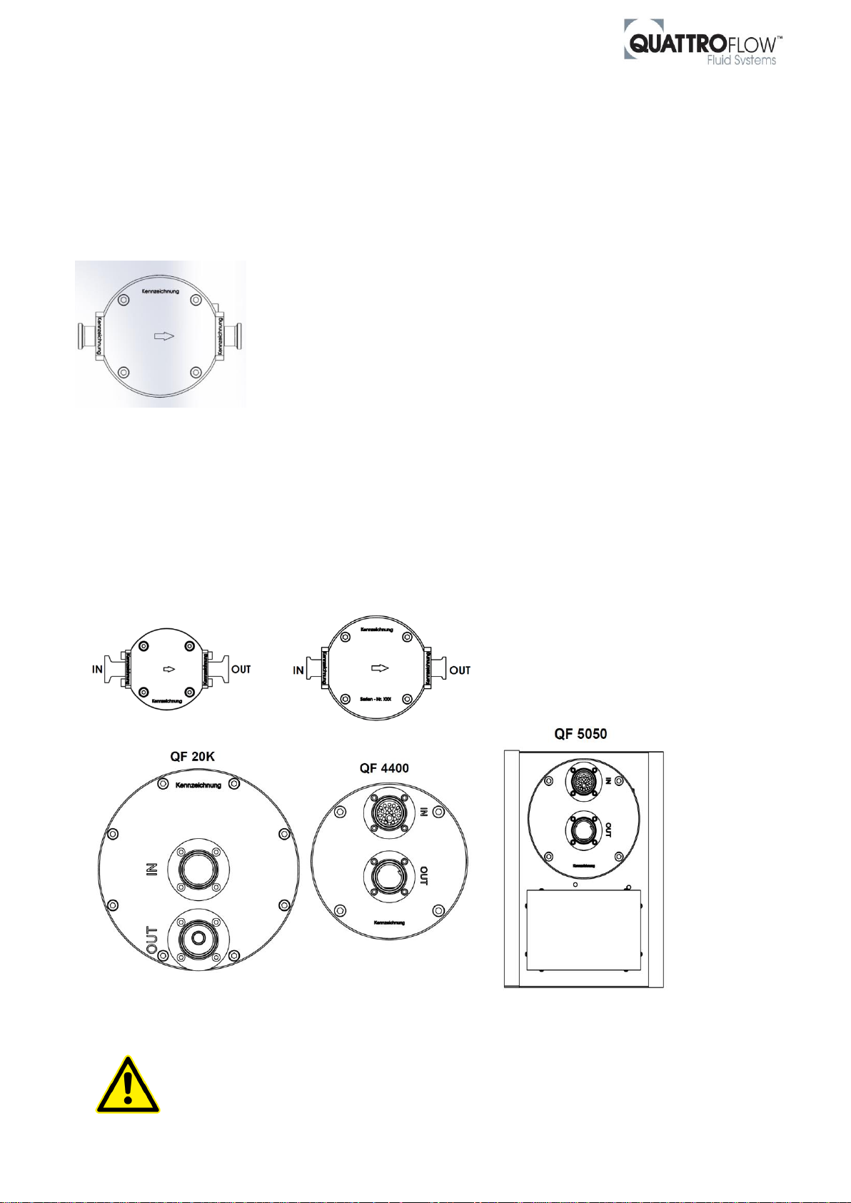
Figure 6 Standard pump chamber orientation for Quattroflow pumps.
Rev. 0
4.5 Flow directions
Due to the internal check valves inside the pump liquid cannot flow backwards through the pump. Please
mind this if the installation needs to be emptied through the pump.
Note: The flow direction is independent from the direction of motor rotation.
4.6 Product connections
Suction and discharge connections of sizes QF150 and QF1200 are mounted
opposite at the pump chamber (“inline”). An arrow on the pump chamber shows
the flow direction (see figure), so that the suction and pressure side can be
clearly identified.
The size QF4400, QF5050 and QF20K have both ports in front of the pump
chamber and are marked with "IN" (inlet) and "OUT" (outlet).
Please see the drawings below for Quattroflow pump chamber orientation which are supplied as standard ex
works. All QF pump chambers can be rotated in 90° steps to adapt the pump to your process and application.
The orientation has no influence on the self-venting behavior.
See also chapter Drainability of Quattroflow Pumps. There you can find further information about the pump
chamber orientation for best drainability.
Standard port and pump chamber orientation from factory:
In case that the pump chambers should be rotated:
Please mind that the clamp ring needs to be rotated as well to access the clamping ring
screw (see installation instructions in the user manual).
If the clamping ring screw is not fixed before operation the pump could be damaged.
Page 11 of 25 www.quattroflow.com
Page 12

Quattroflow Installation, Operation & Troubleshooting Guide
Rev. 0
5 START-UP OPERATIONS
Before start-up of the pump anyone should acquaint oneself with the explanations of the chapter
troubleshooting. Only by this the defect quickly can be realized and eliminated in case of trouble. Problems
which cannot be solved or with an unknown reason should be passed on to the manufacturer.
Before using your pump in your process perform a test run to get used to the specific
properties of the pump.
During start-up pay attention to the warning and safety instructions in the user manual.
5.1 Mounting the pump
All QF standard pumps are mounted on a stainless steel base plate. If you are using an “OEM” pump version
without base plate the pump has to be fixed with the provided mounting.
When installing the pump please consider that around the pump enough space is available for operation and
maintenance. Pay attention to the required space needed for assembly and disassembly of the pump
chamber.
5.2 Mounting the pump chamber
If you have ordered a complete QF pump the stainless steel pump chamber is built-on ex works.
If you have ordered a Quattroflow Single-Use Pump or just a Single-Use pump chamber, the chamber will be
supplied separately. The front crews and the clamping ring screw have to be tightened with the defined
torque which is given in the user manual.
Single-Use Pump chambers must be assembled with the respective pressure plate made of stainless steel.
Please check the given torque for front screws and clamping ring screw in the user manual. If
the clamping ring screw is not fixed before operation the pump could damaged.
It is not possible to use single-use pump chambers without pressure plate.
5.3 Cleaning before start-up (Multiple-Use, Stainless Steel pump chamber)
All Multiple-Use pump chambers made of stainless steel are not cleaned or sterilized ex works. For this
reason prior to the very first use it might make sense to clean and sanitize the pump chamber.
Prior to each use we recommend flushing the pump with a proper fluid (e.g. water or buffer). A commercial
caustic cleaner and/or 0.1N to 0.5N NaOH can be applied. The chosen cleaning agent can be recirculated and
also stored inside the pump chamber. For flushing out of any cleaning agent do not recirculate! Check with
appropriate analytical methods the success of the flushing procedure.
For further cleaning procedures see chapter Cleaning.
Page 12 of 25 www.quattroflow.com
Page 13

Quattroflow Installation, Operation & Troubleshooting Guide
Pump size /
eccentric shaft
Min. pump speed for
self-venting at free output
Min. flow rate for
self-venting at free output
QF150 / 5°
ca. 1000 rpm
ca. 75 l/h
QF1200 / 5°
(Standard)
ca. 500 rpm
ca. 300 l/h
QF1200 / 3°
ca. 900 rpm
ca. 300 l/h
QF4400 / QF5050 / 6°
(Standard)
ca. 500 rpm
ca. 3.200 l/h
QF4400 / QF5050 / 3°
ca. 700 rpm (ca. 80 sec.)
ca. 2250 l/h (ca. 80 sec.)
QF20K / 7°
ca. 150 rpm
ca. 4.000 l/h
Pump size /
eccentric shaft
Pump speed
Suction lift (dry)
QF150 / 5°
3000 rpm
2,0 – 3,0 m
QF1200 / 5°
(Standard)
1800 rpm
4,0 – 4,5 m
QF1200 / 3°
1800rpm
2,5 – 3,0 m
QF4400 / QF5050 / 6°
(Standard)
1200 rpm
4,0 – 4,5 m
QF4400 / QF5050 / 3°
1200 rpm
2,5 – 3,0 m
QF20K / 7°
780 rpm
4,0 – 4,5 m
Rev. 0
5.4 Priming
Quattroflow pumps are self-priming and can run dry (no use of mechanical seals).
Please note that the pump needs to be properly primed in order to achieve a stable flow and low pulsation. A
minimum flow rate is required for the priming (complete removal from air inside the pump chamber). The
following table indicates the minimum required pump speed for water with <0.5 bar discharge pressure.
Please note that these values may depend on the installation. The duration of the vent process at a given
min. pump speed is generally from 5 to 10 seconds.
Table 4 Minimum pump speed and flow rate for self-venting at free output (Water @ RT)
The following table shows the suction high for each pump size. Please note that these values may depend on
the installation.
Table 5 Suction high and respective pump speed (Water @ RT)
Page 13 of 25 www.quattroflow.com
Page 14

Quattroflow Installation, Operation & Troubleshooting Guide
Pump chamber type
CIP
SIP
Autoclave
Multiple-Use pump chamber
made of stainless steel
Valve plate made of stainless steel
Yes Yes Yes
Multiple-Use pump chamber
made of stainless steel
Valve plate made of PP (Polypropylene)
(only for QF4400S / QF5050S)
Yes
No
No
Single-Use pump chamber
made of PP (Polypropylene)
No No Yes
(except QF20K SU)
Single-Use pump chamber
made of injection molded PE (Polyethylene)
(only for QF1200SU)
No No No
Rev. 0
6 CLEANING
The following chapter shows the different cleaning processes for Quattroflow pump chambers. Please note
that not all three cleaning methods are suitable for all types of pump chambers.
6.1 CIP – Cleaning in place
The Quattroflow pump (multiple use) can be used as active CIP-pump to pump the CIP medium through the
complete skid.
Also it is possible that another external pump is used as CIP-pump. Please find some further information for
both operating modes below.
Quattroflow Pump as active CIP pump:
Depending on the products in contact with the pump and given requirements the cleaning procedure needs
to be adapted accordingly. It is the responsibility of the user to verify the cleaning efficiency. Safety rules and
safety measures like protective glasses, gloves and protective clothing have to be followed and used when
working with chemicals like sodium hydroxide (NaOH).
As a general rule we recommend to clean the pump according to the following procedure:
1. Pre rinse the pump with pure water, until residual amounts of product have been removed.
2. Cleaning step with 0.5 M NaOH (ca. 50°C) at 80% of the maximum RPM for approximately 30 min.
Check before, if surrounding conditions (e.g. pipe diameter, system pressure rating) allow to operate
the pump at this speed.
3. Final rinse with pure water, until neutrality has been achieved (e.g. by measuring conductivity or pH
of the rinse water).
Temperature for CIP-medium: max. 90 °C (194 °F)
Pressure: max. 4 bar (58 PSI)
The flow rate should not be higher than 80% of the maximum flow rate which is given for
the used Quattroflow pump (please see given table below).
Please check the chemical resistance of the product wetted materials against the used CIP
mediums.
Page 14 of 25 www.quattroflow.com
Page 15
Quattroflow Installation, Operation & Troubleshooting Guide
Pump size
Max. flow rate for CIP
QF active or passive mode
Max. 80 % Pump speed
QF150
144 l/h
QF1200
960 l/h
QF4400 / QF5050
4000 l/h
QF20K
12800 l/h
Pump size: QF150
Pressure sensor: 1/2“
Flow rate [l/h]
Differential pressure [barg]
47
0,1
70
0,1
91
0,2
114
0,3
135
0,5
Rev. 0
CIP with external pump:
If you use another external pump for you CIP-process, the passive Quattroflow Pumps will be rinsed freely.
Please note the given important information below.
Temperature for CIP-medium: max. 90 °C (194 °F)
Pressure: max. 4 bar (58 PSI)
The flow rate should not be higher than 80% of the maximum flow rate which is given for
the used Quattroflow pump (please see given table below).
Please check the chemical resistance of the product wetted materials against the used CIP
mediums.
The fluid path through the pump is only open in flow direction, from inlet to outlet
connection port. It is not possible to rinse the pump in reversed flow direction, because
the check valve will not open.
Table 6 Max. flow rate for CIP processes. Quattroflow pump as active pump or as passively rinsed.
Pressure drop:
The following tables show the approx. pressure drop which is generated by the rinsed Quattroflow Pump
chamber, when using an external CIP-pump.
Table 7 Pressure drop of QF150 pump chamber at different flow rates. Water @ RT
Page 15 of 25 www.quattroflow.com
Page 16

Quattroflow Installation, Operation & Troubleshooting Guide
Pump size: QF1200
Pressure sensor: 3/4“
Flow rate [l/h]
Differential pressure [barg]
89
< 0,1
170
< 0,1
348
0,1
516
0,3
680
0,5
840
0,6
Pump size:
QF4400 / QF5050
Pressure sensor: 2“
Flow rate [l/h]
Differential pressure [barg]
2000
0,2
2500
0,2
3000
0,2
3500
0,3
3800
0,3
4000
0,3
Rev. 0
Table 8 Pressure drop of QF1200 pump chamber at different flow rates. Water @ RT
Table 9 Pressure drop of QF4400 / QF5050 pump chamber at different flow rates. Water @ RT
Page 16 of 25 www.quattroflow.com
Page 17

Quattroflow Installation, Operation & Troubleshooting Guide
Rev. 0
6.2 SIP - Steaming in place
There are some important points to observe for cleaning the Quattroflow pump with hot steam:
For steaming in place the pump chamber has to be installed on the pump drive
During the steaming process the pump must not run
During the steaming process the temperature in the pump must not exceed 130°C (266°F)
SIP process should not longer than 30 min.
The cooling down process of the pump chamber should be against room temperature
Depending on the SIP conditions it may be necessary to shorten the maintenance intervals for the
elastomers significantly*
The tightening torques of the front bolts of the pump chamber have to be verified after each SIP
cycle (please see user manual for given torque values)
In case the listed points above are not observed, there is a high risk for damage the
elastomer parts in the pump chamber.
* Typically it is possible to use the same elastomer parts (diaphragms, valves, O-Rings) for 6 – 8 SIP cycles, if
the given points above are observed. This number of maximum SIP cycles depends on further process
conditions (e.g. medium, temperature, flow rate, back pressure…).
Condensate removal after SIP process
After SIP-process Quattroflow pumps may contain a non-recoverable volume of condensate which depends
on the pump size, pump type and process conditions.
To remove the full amount of condensate out of the pump chamber there is the possibility to mount the
pump in vertical position. Please see chapter
Full drainability: Vertical position of the pump (pump chamber downwards) for more information.
Blow down after SIP process
Quattroflow MU Pumps can handle a so called blow down process that is often executed after the SIP cycle.
Blow down is used cooling down the system and removing the residual condensate out of the system over
steam traps. For this purpose sterilized compressed air is blown in the system. Concurrent the compressed air
is used to hold a constant over pressure in the system to avoid a vacuum that is caused by the condensing
steam.
Quattroflow Pumps are not suitable for vacuum on the suction or/and discharge side because it could
cause damage at the diaphragms and valves.
Quattroflow pumps should not run while the blow down and cooling down process.
Steam and compressed air can only flow in the default direction from inlet to outlet side of the pump
Page 17 of 25 www.quattroflow.com
Page 18
Quattroflow Installation, Operation & Troubleshooting Guide
Rev. 0
6.3 Autoclave
For autoclaving of the pump chamber we recommend the following steps.
1. CIP of the pump chamber with any suitable process
2. Empty the pump
3. Remove the pump chamber from the pump drive
4. Close in and outlet of the pump e.g. by connecting hoses. Ensure that a free interchange of
gas and steam over a sterile barrier (e.g. sterile filter) at in- and outlet is available.
5. Autoclaving of the prepared pump chamber in a vacuum autoclave:
max. 130°C (266°F)
max. 30 min.
Follow instructions of the autoclave manufacturer
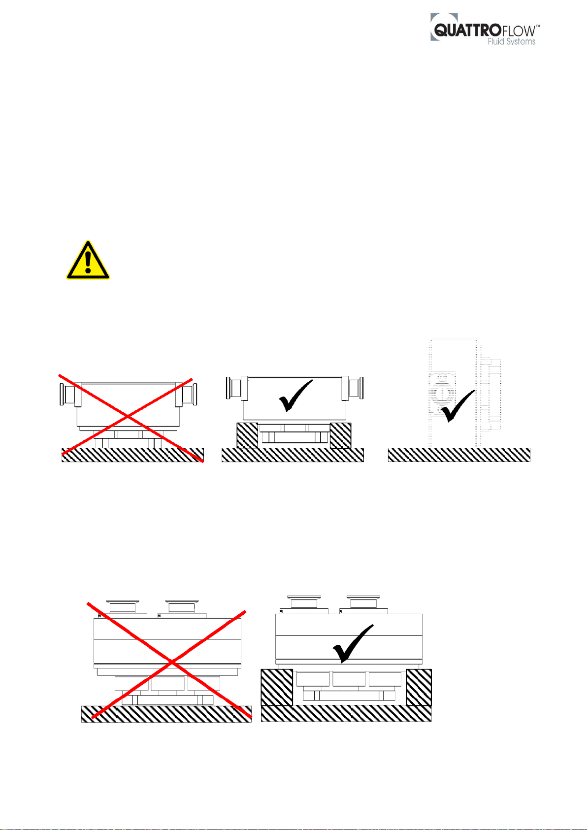
Please make sure that the pump chamber is not placed on the clamp ring during the
autoclave process. The clamp ring should not be loaded during autoclaving.
QF150, QF1200
QF4400, QF5050 (QF20K SU not autoclavable)
Page 18 of 25 www.quattroflow.com
Page 19
Quattroflow Installation, Operation & Troubleshooting Guide
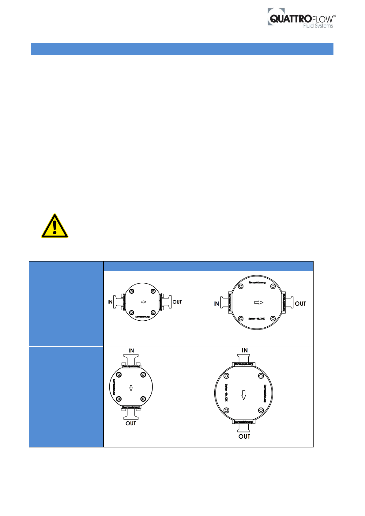
QF150
QF1200
Standard orientation
Pump drive
horizontally (standard)
pump chamber
horizontally mounted
Optimized drainability *
Pump drive
horizontally (standard)
pump chamber
vertically mounted
Rev. 0
7 DRAINABILITY OF QUATTROFLOW PUMPS
After draining, Quattroflow pumps may contain a non-recoverable volume of liquid which depends on the
pump size, pump type and orientation of the pump chamber.
To support maximum product recovery and drainability we give the following information:
7.1 Optimized drainability: orientation of the pump chamber
There is the possibility to rotate the pump chamber in 90° steps for all Quattroflow pump sizes. This rotation
is independent of the orientation of the pump drive which stands standardly horizontally on the ground.
The following two tables show the standard orientation of all QF pump sizes and the pump chamber
orientation for an optimized drainability.
For the small Quattroflow pump series QF150 and QF1200 we recommend a vertically mounted pump
chamber (inlet up, outlet down) for optimized drainability.
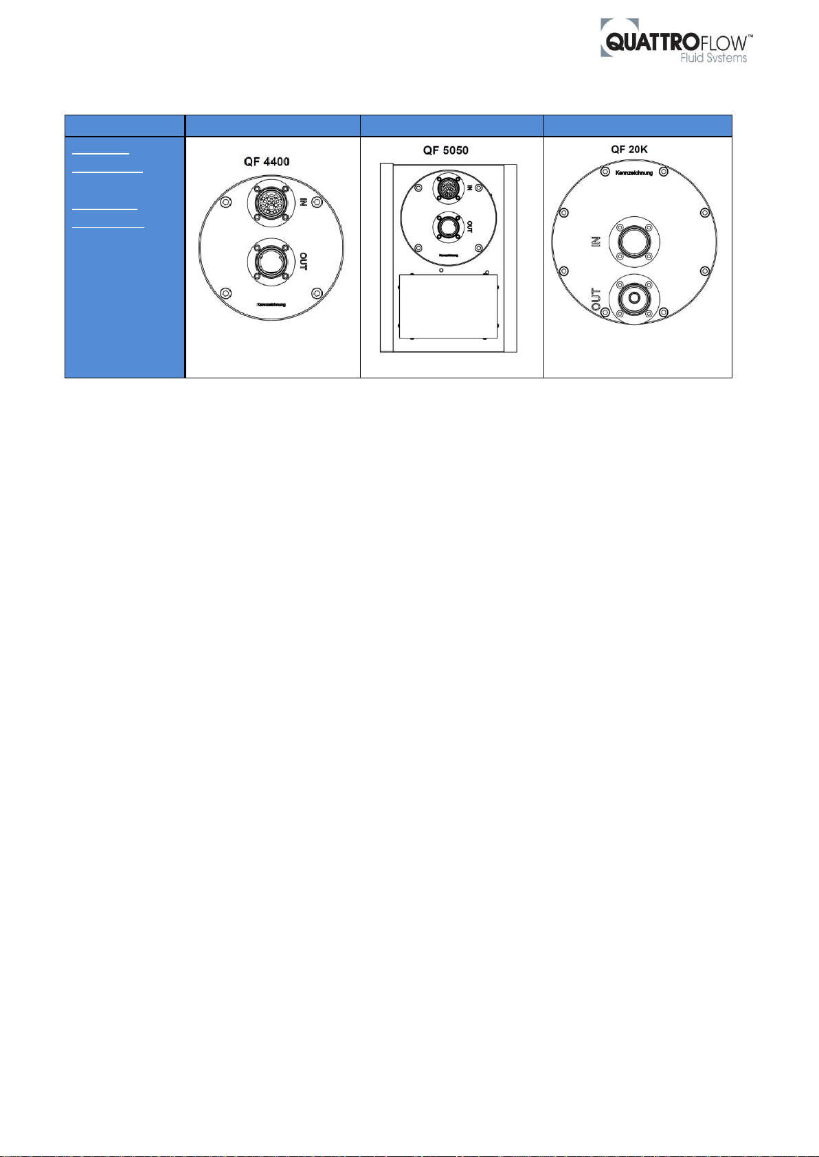
The shown standard orientation for QF4400, QF5050 and QF20K pump series is also the recommended
orientation for optimized drainability.
In case that the pump chambers should be rotated:
Please mind that the clamp ring needs to be rotated as well to access the clamping ring
screw (see installation instructions).
If the clamping ring screw is not fixed before operation the pump could be damaged.
Table 10 Standard and optimized orientation of QF pump chambers (QF150, QF1200).
* Please note that the fluid path (inlet and outlet valves) opens automatically, if there is small over
pressure or hydrostatic head on the inlet site of the pump chamber. Please check if an additional valve
before the inlet connection port is needed in your system.
Page 19 of 25 www.quattroflow.com
Page 20
Quattroflow Installation, Operation & Troubleshooting Guide
QF4400
QF5050
QF20K
Standard
orientation
=
Optimized
drainability
Pump drive
horizontally
(standard)
inlet up,
outlet down
(standard)
Rev. 0
Table 11 Standard and optimized orientation of QF pump chambers (QF4400, QF5050, QF20K).
Page 20 of 25 www.quattroflow.com
Page 21
Quattroflow Installation, Operation & Troubleshooting Guide
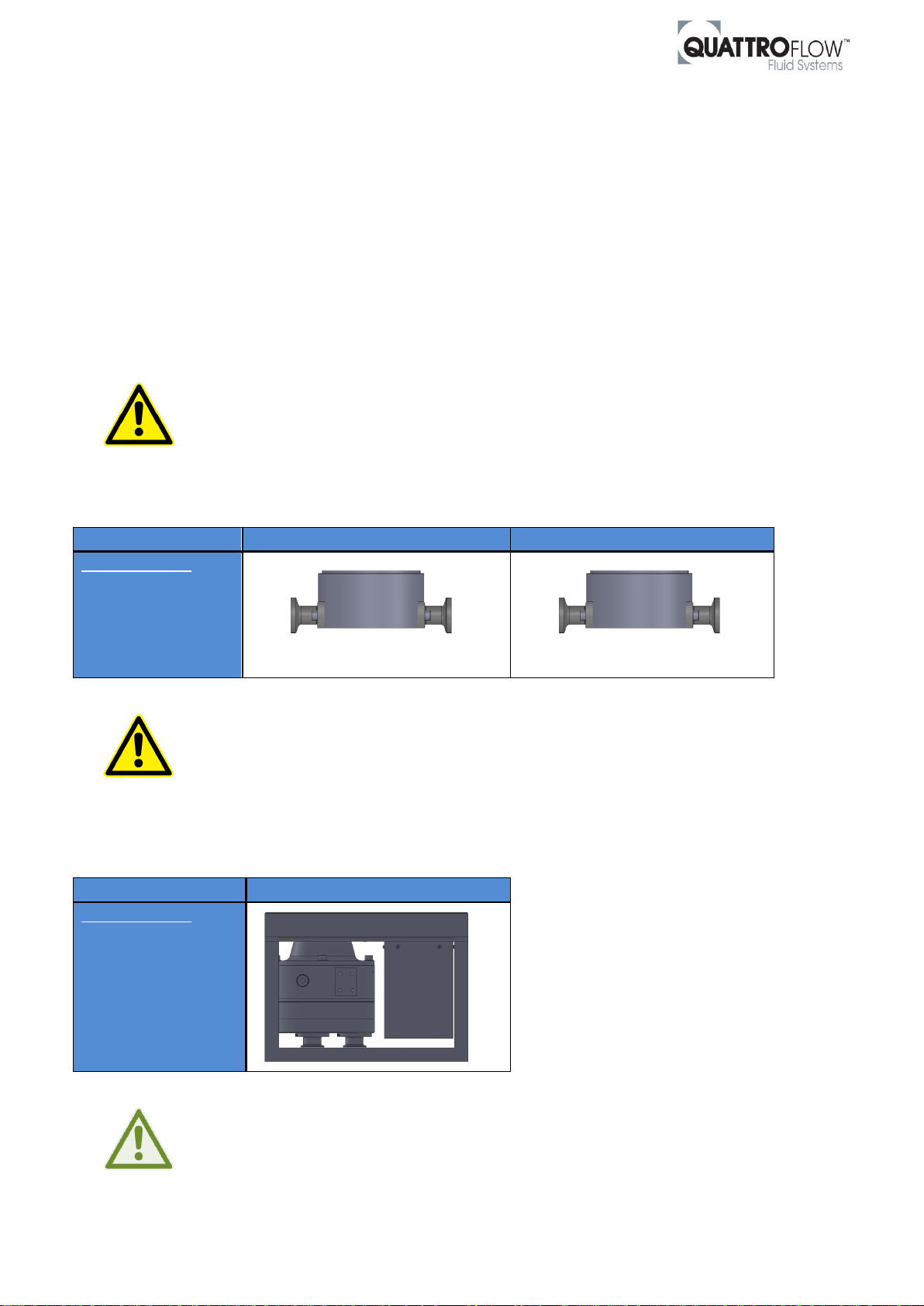
QF150
QF1200
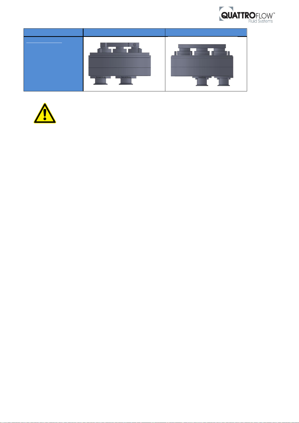
Full drainability
Pump drive
Vertically,
Pump chamber
downwards
QF5050
Full drainability
Complete pump is
rotated,
Pump chamber
downwards
Rev. 0
7.2 Full drainability: Vertical position of the pump (pump chamber downwards)
To reach a full drainability of Quattroflow Pump chambers there is the possibly to mount the complete pump
drive and pump head in vertically position. There are some figures below which show this orientation
exemplary.
For the reason that the pump chamber shows downwards the medium will flow out of the inlet and outlet
port caused by the gravitation.
For all pump sizes we recommend installing valves both at the inlet and the outlet site of the pump
chamber for draining after the process or cleaning procedure is finished.
For new or existing Quattroflow pump with gear motors, there are some points which have
to be considered for horizontal mounting. Please contact the support team to get further
information.
Figure 7 QF150 and QF1200 orientation for full drainability.
Figure 8 QF5050 orientation for full drainability.
Page 21 of 25 www.quattroflow.com
Please contact the support team to get more information on vertical installation of QF150
and QF1200 pumps.
There is nothing else to consider mounding the QF5050 pump as shown above.
QF5050 pump is designed to operate in all orientations.
Page 22
Quattroflow Installation, Operation & Troubleshooting Guide
QF4400
QF20K
Full drainability
Pump drive
Vertically,
Pump chamber
downwards
Rev. 0
Figure 9 QF4400 and QF20K orientation for full drainability.
Please contact the support team to get more information on vertical installation of QF4400
and QF20K pumps.
Page 22 of 25 www.quattroflow.com
Page 23
Quattroflow Installation, Operation & Troubleshooting Guide
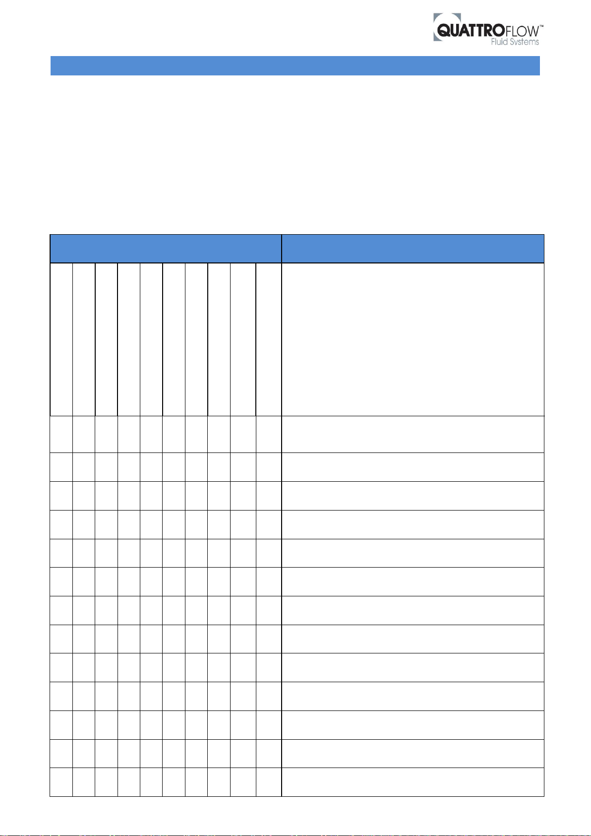
Operating troubles
Cause / remedial action
Pump does not start
Pump does not prime
Output is not obtained
Pressure head is not obtained
Output is not consistent
Pump operates noisy / vibrations
Pump is leaky
Motor gets to warm
Too high pulsation
Diaphragm damage
X X
The front screws of the pump chamber / pressure plate are
not tightened enough. Fix it with the defined tightened
torque.
X
Check the direction of flow showed by the arrow on the pump,
in case of wrong way, turn the pump head.
X X X
Check suction pipeline and TC-seals for tightness.
X X X X
Check suction head -> increase suction line cross section.
X X X
Check viscosity of liquid pumped.
X
Check power supply and cables.
X X X X
Avoid air inclusions in the liquid to be pumped.
X X
Check pressure head-open valve in discharge line completely,
remove obstruction in discharge line.
X X X
The diameters of the pipes in suction or pressure line are too
small -> risk for cavitation.
X
Check the coupling halves. They must be fixed with a lash ->
see Quattroflow manual.
X
Check longitudinal play of coupling rod pins. The spider made
of plastic might be worn.
X X X
Check whether foreign bodies in pump.
X X
Pump stopped by the thermal circuit breaker. Allow the motor
to cool down – maybe reduce the power consumption.
Table 12 Troubleshooting Table 1
Rev. 0
8 TROUBLESHOOTING
Quattroflow pumps operate very reliable and error-free, if they will be operated and serviced in accordance
with the instruction manual. If there is still a problem the following table should help detecting and fixing the
cause by yourself.
Please read also the official and recent operating manuals and safety instructions carefully which are
available for Quattroflow Pumps and accessories.
If you would like to contact the manufacturer for support, please keep the serial number of the pump and
information about the process parameters available.
Page 23 of 25 www.quattroflow.com
Page 24
Quattroflow Installation, Operation & Troubleshooting Guide
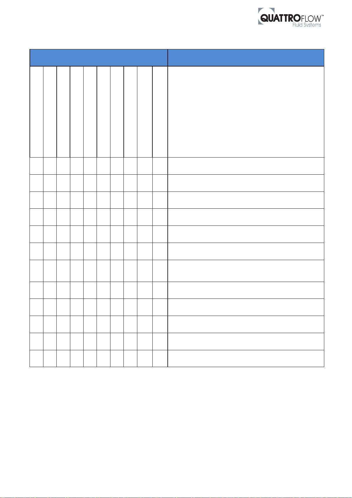
Operating troubles
Cause / remedial action
Pump does not start
Pump does not prime
Output is not obtained
Pressure head is not obtained
Output is not consistent
Pump operates noisy / vibrations
Pump is leaky
Motor gets to warm
Too high pulsation
Diaphragm damage
X X
Bearings are worn or defective and must be replaced.
X
The valves are dry (e.g. not in use for a long time), deformed
or worn. Change valve or wet the pump.
X
The diaphragm is burst
-> replace with respective elastomer service-kit.
X X X X
O–rings between valve plate and pump housing are defective
-> Replace with respective elastomer service-kit.
X X
The clamping ring screw got loose
-> fix it with the defined torque.
X
Parameters of the control panel are wrong
-> check basic settings.
X
Pump may not start in manual mode if configured for remote
operation (e.g. external 4-20mA signal); check parameter
settings.
X
Pump after SIP cooled down too fast - slow cooling with room
temperature.
X
Too high vacuum on suction side of the pump.
X
Diaphragm are not correctly installed on supports
-> see QF manual.
X
Pump chamber is not completely vented
-> see chapter Start-up operations.
X
Check chemical compatibility of elastomers.
Table 13 Troubleshooting Table 2
Rev. 0
Continuation of Troubleshooting Table 1:
Page 24 of 25 www.quattroflow.com
Page 25

Quattroflow Installation, Operation & Troubleshooting Guide
Rev. 0
ALMATEC Maschinenbau GmbH
Carl-Friedrich-Gauss-Str. 5 · 47475 Kamp-Lintfort · Germany
Telephone +49.2842.9610 · Telefax ++49.2842.96140
http://www.almatec.de · e-mail: [email protected]
Subject to change without notice.
Page 25 of 25 www.quattroflow.com
 Loading...