

Page 1
Appendix to the Operating and
Installation Instructions
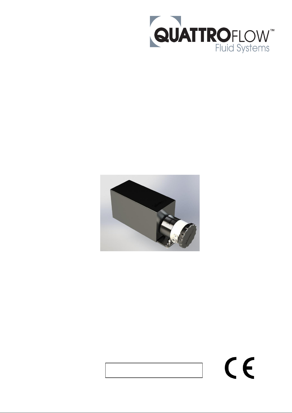
QF1200SU
EZ-Set
Please read this appendix and the pump manual
carefully before start-up of the pump and take care of an
appropriate instruction of the operating staff.
Attention!
Please regard the warning and safety advices!
Original Instruction
Page 2

EZ-Set, Appendix to pump manual of QF1200SU; edition 11/2018; page 2 of 11
Contents
1. General remarks ................................................................................................. 3
1.1. Overview of the components ........................................................................... 3
2. Disassembly ....................................................................................................... 4
2.1. Unscrewing the hand wheel ............................................................................. 4
2.2. Loosen the bayonet-plate ................................................................................ 4
2.3. Dismounting the subassembly ......................................................................... 5
2.4. Dismounting the pump chamber ...................................................................... 5
3. Assembly ............................................................................................................ 6
3.1. Unscrewing the locking screw .......................................................................... 6
3.2. Alignment of the shaft-bearing-cap-unit ........................................................... 6
3.3. Mounting the pump chamber ........................................................................... 7
3.4. Fasten the locking-screw ................................................................................. 7
3.5. Mounting the subassembly ................................................................ .............. 8
3.6. Fasten the bayonet-plate ................................................................................. 8
3.7. Fasten the handwheel ...................................................................................... 9
4. Retrofit a pump to EZ-Set ................................................................................ 10
4.1. Replacing the shaft-bearing-cap-unit ............................................................. 10
4.2. Fasten the studs ................................................................ ........................... 10
Page 3
EZ-Set, Appendix to pump manual of QF1200SU; edition 11/2018; page 3 of 11
1. General remarks
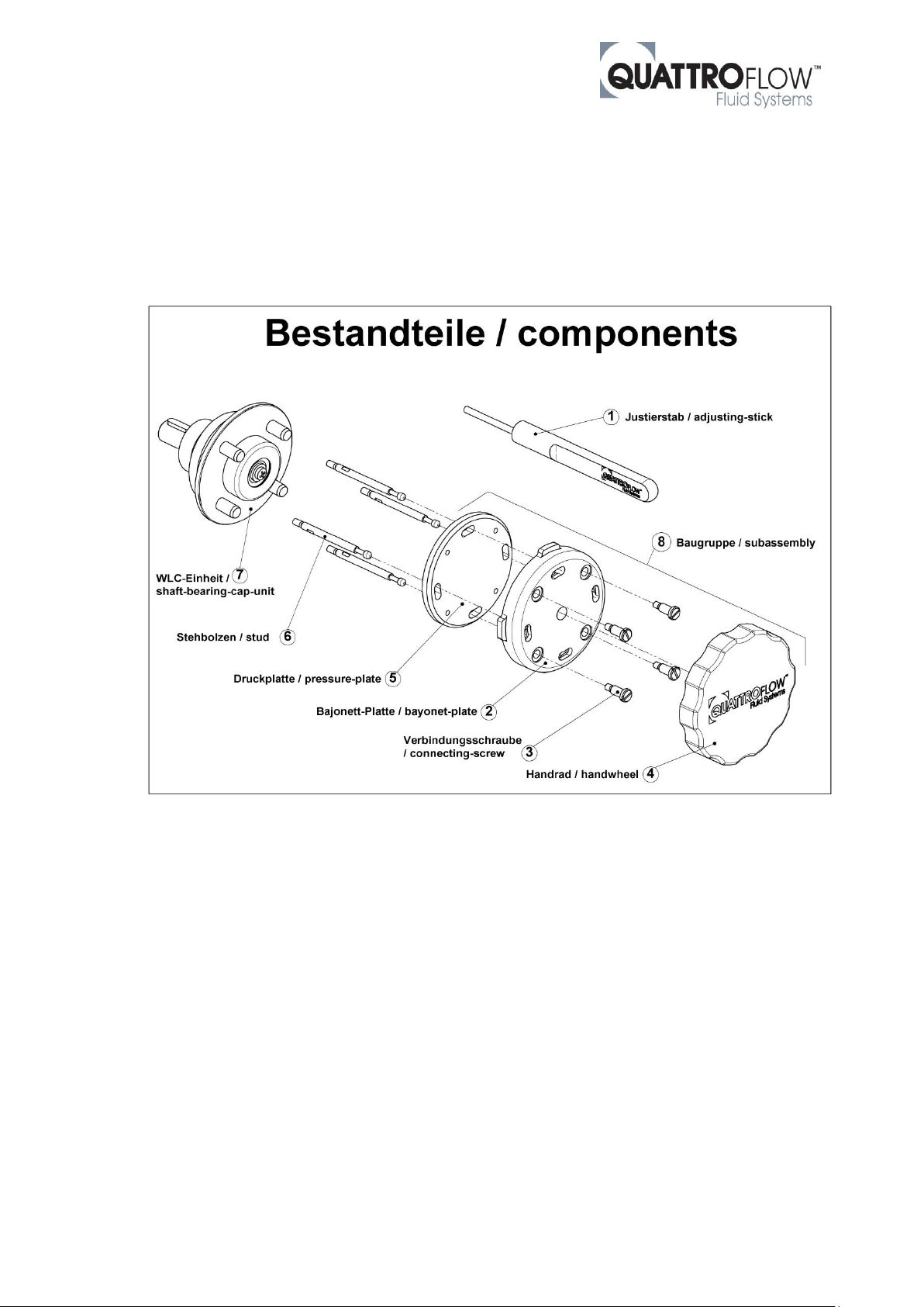
1.1. Overview of the components
Page 4
EZ-Set, Appendix to pump manual of QF1200SU; edition 11/2018; page 4 of 11
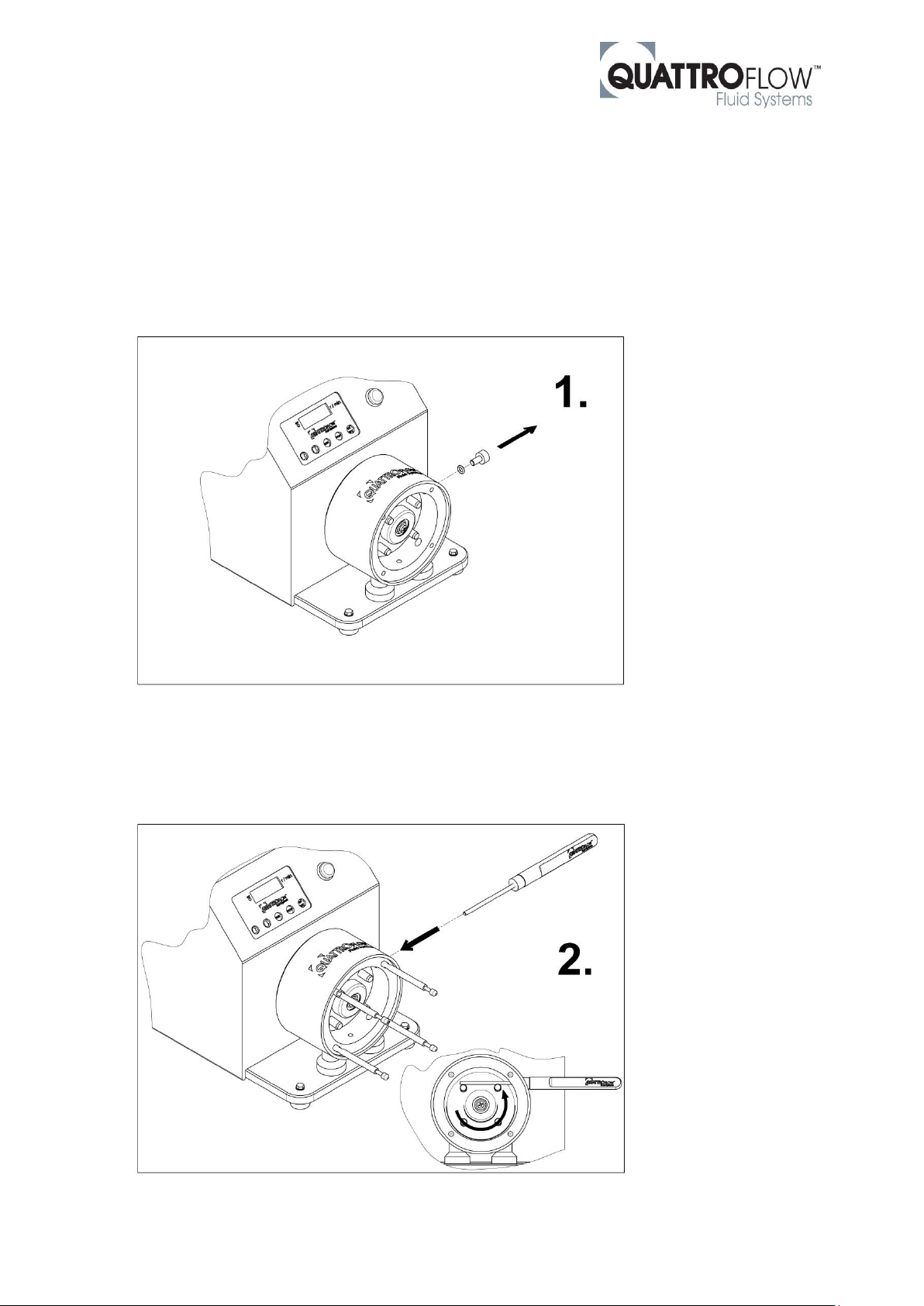
2. Disassembly
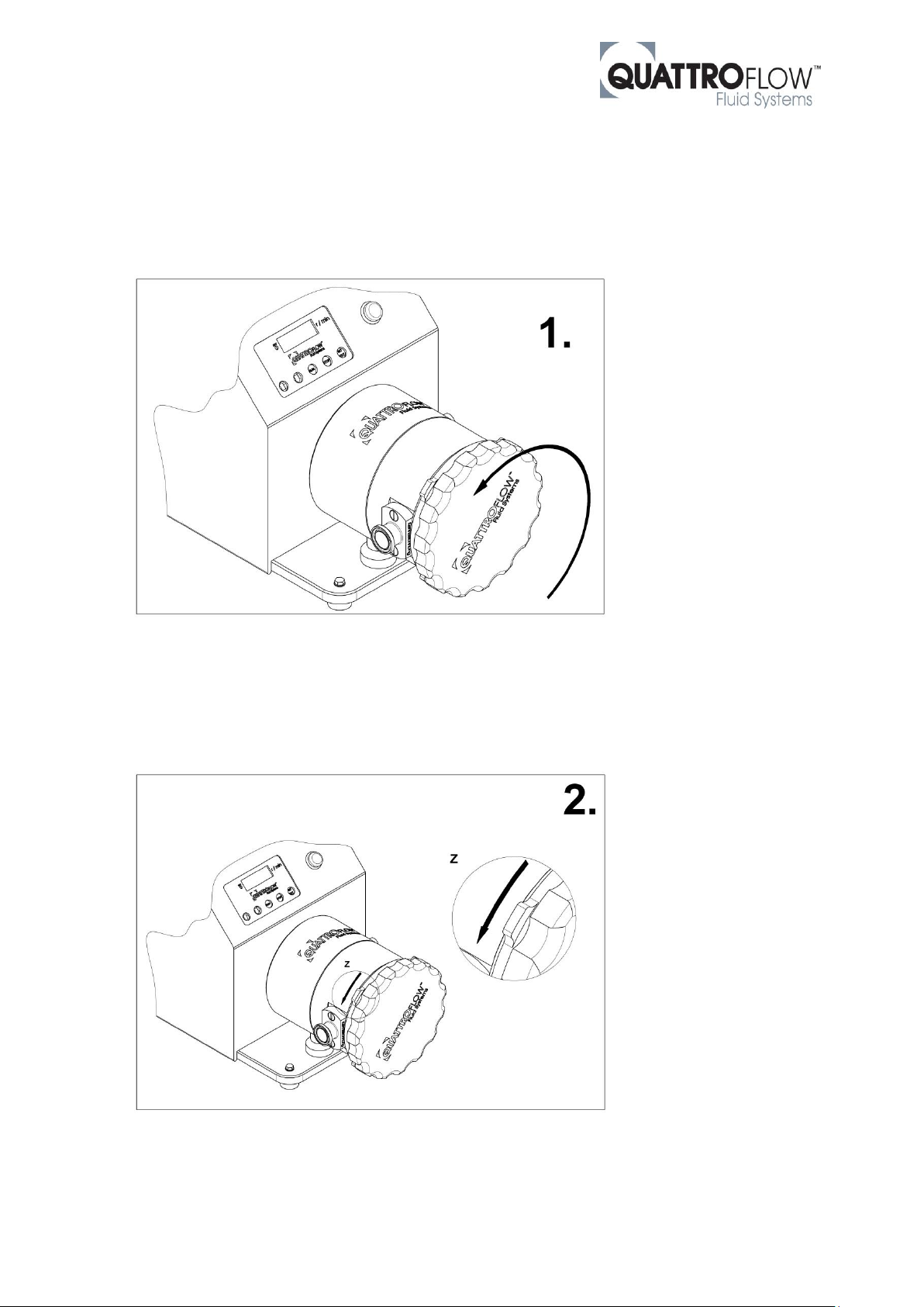
2.1. Unscrewing the hand wheel
Unscrew the hand wheel (item 4) in rotational direction counter-clock wisely. 2-3 cycles are enough. It
is not necessary to screw off the hand wheel completely.
2.2. Loosen the bayonet-plate
Loosen the bayonet-plate (item 2) in rotational direction counter-clock wisely. The bayonet-closure
snaps out after about 20° rotation-angle.
Page 5
EZ-Set, Appendix to pump manual of QF1200SU; edition 11/2018; page 5 of 11
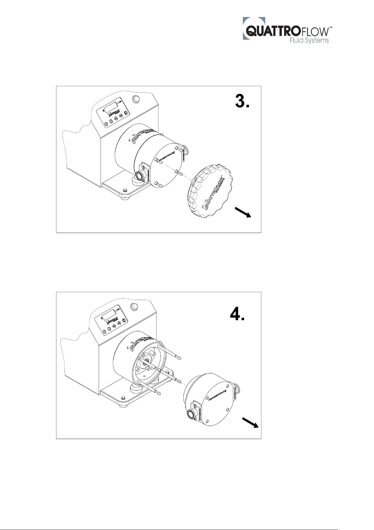
2.3. Dismounting the subassembly
Pull off the whole subassembly (item 8) to the front side.
2.4. Dismounting the pump chamber
Pull the pump chamber off the studs (item 6).
Page 6
EZ-Set, Appendix to pump manual of QF1200SU; edition 11/2018; page 6 of 11
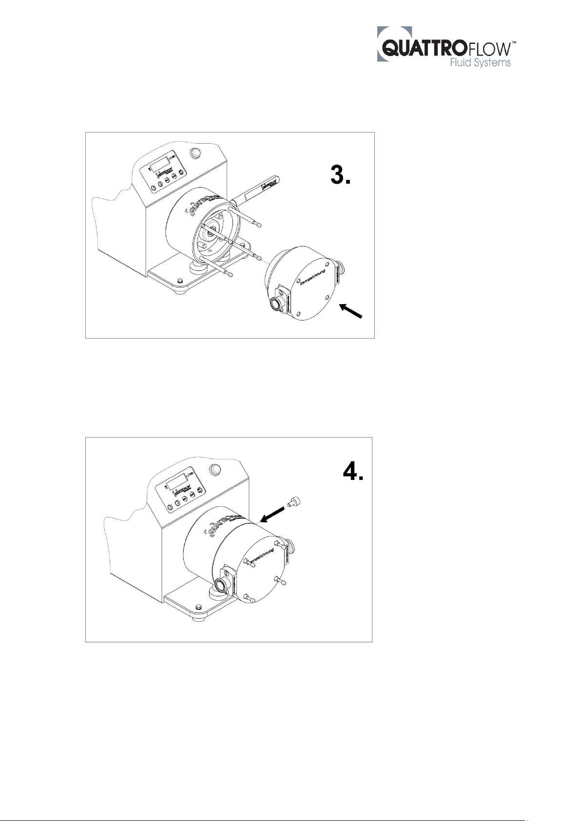
3. Assembly
The use of the adjusting stick (item 1) and thus the steps 3.1./3.2./3.4. are not absolutely necessary, but
facilitate the assembly of the pump chamber to fix the position of the cap of the shaft-bearing-cap-unit.
3.1. Unscrewing the locking screw
Loosen the locking screw with a hex head wrench (Size 5mm).
3.2. Alignment of the shaft-bearing-cap-unit
Page 7

EZ-Set, Appendix to pump manual of QF1200SU; edition 11/2018; page 7 of 11
Align the cap of the shaft-bearing-cap-unit by the help of the adjusting stick (item 1).
Page 8
EZ-Set, Appendix to pump manual of QF1200SU; edition 11/2018; page 8 of 11
3.3. Assembling the pump chamber
Assemble the pump chamber by the help of the studs (item 6). After that pull out the adjusting stick (item
1).
3.4. Mounting the locking screw
Tighten the locking screw with the help of a hex head wrench (Size 5mm).
Page 9
EZ-Set, Appendix to pump manual of QF1200SU; edition 11/2018; page 9 of 11
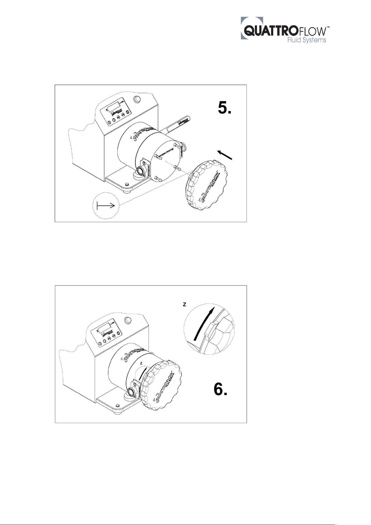
3.5. Mounting the subassembly
Assemble the whole subassembly (item 8) by placing the studs (item 6) into the provided holes and
press it on. In addition to this, the mark on the bajonet-plate (item 2) should be visible.
3.6. Fasten the bayonet-plate
Fasten the bayonet-plate (item 2) by turning it clockwisely. The bayonet-closure snaps in after about
20° rotation-angle.
If the bajonet-plate is not rotatable, it is possible that the handwheel (item 4) is not loosened enough
and need a few more rotations clockwisely, but without unscrewing it completely.
Page 10
EZ-Set, Appendix to pump manual of QF1200SU; edition 11/2018; page 10 of 11
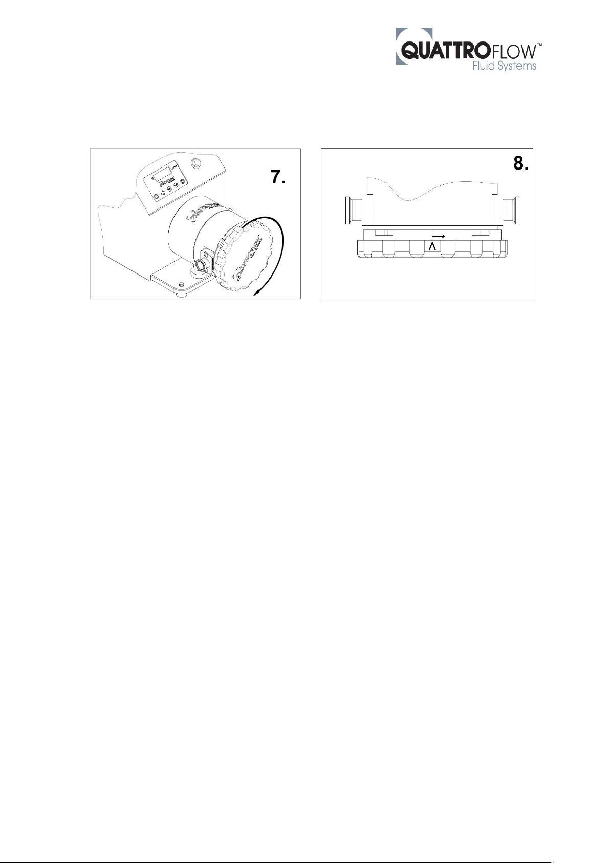
3.7. Fasten the hand wheel
Fasten the hand wheel (item 4) by turning it clockwisely (figure 7). Turn the hand wheel until a noticeable
drag appears. After that, the mark of the hand wheel must be turned at least to the mark of the bayonetplate or beyond (figure 8).
Page 11
EZ-Set, Appendix to pump manual of QF1200SU; edition 11/2018; page 11 of 11
4. Retrofit a pump to EZ-Set
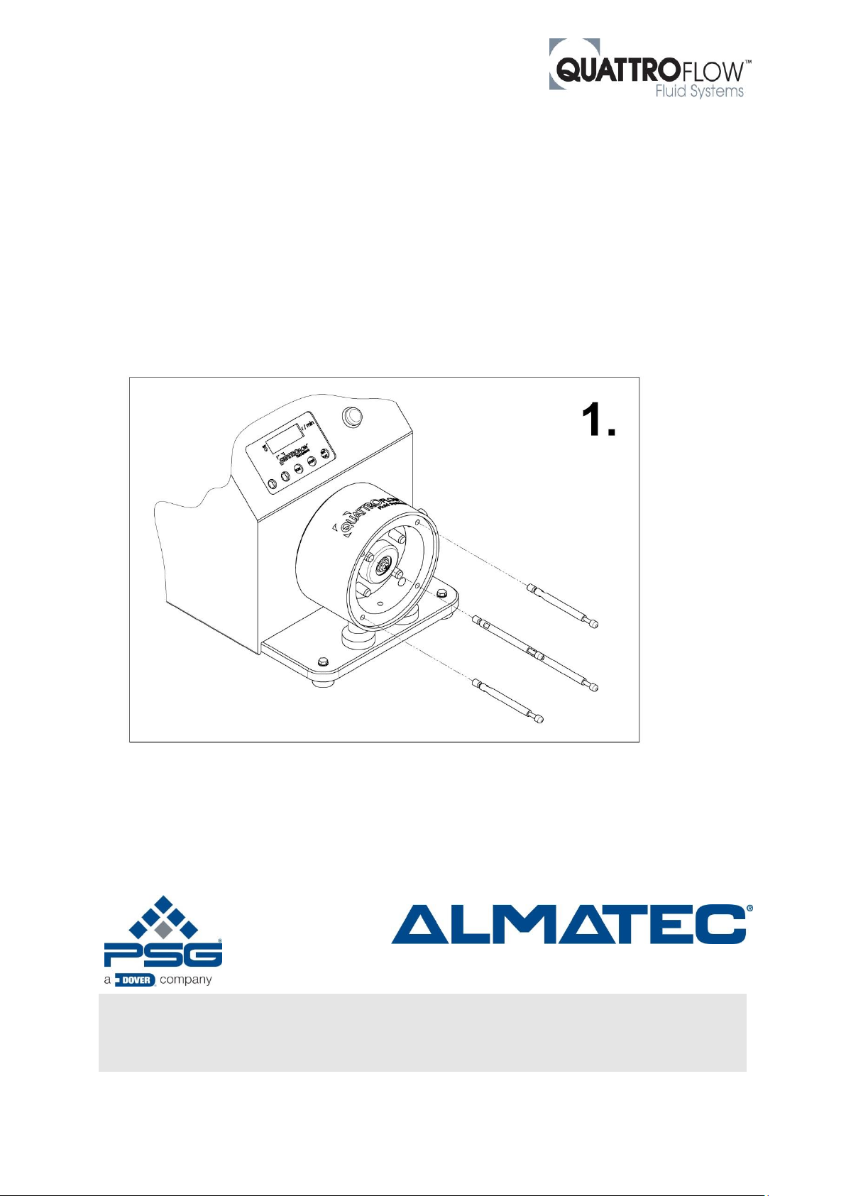
An existing standard QF1200 single-use pump can be retrofitted quickly and easily to the EZ-Set system.
For this purpose, the WLC (shaft-bearing-cap) unit must be replaced and the studs screwed in.
4.1. Replacing the shaft-bearing-cap-unit
The replacement of the shaft-bearing-cap unit (item 7) is described in the chapter 4.2 of the pump
manual.
4.2. Fasten the studs
Fasten the studs (item 6) in the bearing-shell of the ring-drive-unit and tighten them with the help of an
open-end spanner (A/F 5mm).
Quattroflow is a brand of ALMATEC Maschinenbau GmbH.
ALMATEC is constantly working on improvements of the pump. Modifications of the design or
materials might be done without prior notice.
Subject to change without notice, 2018-11 (replaces 2018-05)
ALMATEC Maschinenbau GmbH
Hochstraße 150-152· D-47228 Duisburg, Germany
Telefon +49 (0) 2065 89205-0 · Fax +49 (0) 2065 89205-40
www.quattroflow.com · [email protected]
 Loading...