

Page 1

Service Manual
Room Air Conditioner
HQ-2243TH,LWC081
WARNING
This service information is designed for experienced repair technicians only and is not designed for use by the general public.
It does not contain warnings or cautions to advise non-technical individuals of potential dangers in attempting to service a product.
Products powered by electricity should be serviced or repaired only by experienced professional technicians. Any attempt to
service or repair the product or products deal with in this service information by anyone else could result in serious injury or death.
© 2003 Matsushita Electric Industrial co., Ltd.
All rights reserved. Unauthorized copying and
distribution is violation of law.
ORDER NO. RAC0212002C1
E9
Page 2

—2—
1. PREFACE
1.1 SAFETY PRECAUTIONS ...............................2
1.2 INSULATION RESISTANCE TEST.................2
1.3 FEATURES.....................................................3
1.4 SPECIFICATIONS ..........................................3
1.5 CONTROL LOCATIONS.................................4
2.
DISASSEMBLY INSTRUCTIONS
2.1 MECHANICAL PARTS....................................6
2.1.1 FRONT GRILLE.....................................6
2.1.2 CABINET................................................6
2.1.3 CONTROL BOX.....................................6
2.2 AIR HANDLING PARTS..................................7
2.2.1 COVER (AT THE TOP)..........................7
2.2.2 BLOWER................................................7
2.2.3 FAN........................................................8
2.2.4 SHROUD................................................8
2.3 ELECTRICAL PARTS.....................................8
2.3.1 MOTOR..................................................8
2.3.2 COMPRESSOR.....................................8
2.3.3 CAPACITOR..........................................9
2.3.4 POWER CORD......................................9
2.3.5 THERMOSTAT ......................................9
2.3.6 ROTARY SWITCH...............................10
2.3.7 SYNCHRONOUS MOTOR ..................10
2.4 REFRIGERATION CYCLE............................11
2.4.1 CONDENSER......................................11
2.4.2 EVAPORATOR....................................11
2.4.3 CAPILLARY TUBE...............................11
3.
INSTALLATION
3.1 HOW TO INSTALL THE UNIT ......................14
3.2 WINDOW REQUIREMENTS.........................14
3.3 INSTALLATION KITS CONTENTS...............14
3.4 SUGGESTED TOOL REQUIREMENTS.......16
3.5 CABINET INSTALLATION............................17
4.
TROUBLESHOOTING GUIDE
4.1 OUTSIDE DIMENSIONS...............................19
4.2 PIPING SYSTEM ..........................................19
4.3 TROUBLESHOOTING GUIDE......................20
5. SCHEMATIC DIAGRAM
5.1 CIRCUIT DIAGRAM......................................25
6. EXPLODED VIEW..................................26
7. REPLACEMENT PARTS LIST.......27
1. PREFACE
This
SERVICE MANUAL provides various service information, including the mechanical and electrical
parts etc. This room air conditioner was manufactured and assembled under a strict quality control system.
The refrigerant is charged at the factory. Be sure to read the safety precautions prior to servicing the unit.
1.1 SAFETY PRECAUTIONS
1. When servicing the unit, set the ROTARY SWITCH
or POWER SWITCH to OFF and unplug the power
cord.
2. Observe the original lead dress.
If a short circuit is found, replace all parts which
have been overheated or damaged by the short
circuit.
3. After servicing the unit, make an insulation
resistance test to protect the customer from being
exposed to shock hazards.
1.2
INSULATION RESISTANCE TEST
1. Unplug the power cord and connect a jumper
between 2 pins (black and white).
2. The grounding conductor (green or green & yellow)
is to be open.
3. Measure the resistance value with an ohm meter
between the jumpered lead and each exposed
metallic part on the equipment at all the positions
(except OFF or O) of the ROTARY SWITCH.
4. The value should be over 1MΩ.
CONTENTS
Page 3

—3—
1.3 FEATURES
• DESIGNED FOR COOLING ONLY
• POWERFUL AND INCREDIBLE COOLING
• BUILT-IN ADJUSTABLE THERMOSTAT
• WASHABLE ONE-TOUCH FILTER
• COMPACT SIZE
1.4 SPECIFICATIONS
HQ-2243TH
POWER SUPPLY Ø, V, Hz
COOLING CAPACITY Btu/h.
POWER INPUT W
RUNNING CURRENT A
EER Btu/h.W
OPERATING
INDOOR °F(°C)
CONDITION
OUTDOOR
°F(°C)
REFREIGERANT (R-22) CHARGE
EVAPORATOR
CONDENSER
FAN
INDOOR
OUTDOOR
FAN SPEED
FAN/COOLING
FAN MOTOR
OPERATION CONTROL
ROOM TEMP. CONTROL
AIR DIRECTION VERTICAL
CONTROL
HORIZONTAL
CONSTRUCTION
PROTECTOR
COMPRESSOR
FAN MOTOR
POWER CORD
DRAIN SYSTEM
NET WEIGHT lbs(kg)
DIMENSION(W*H*D) inch(mm)
1, 230/208, 60
2,350/2,300
2,500/2,450
11.2/12.0
9.4
DB : 80(26.7) WB : 67(19.4)
DB : 95(35) WB : 75(23.9)
980g (34.6 oz)
3 ROW 15 STACKS, SLIT-FIN TYPE
2 ROW 19 STACKS, LOUVERED-FIN TYPE
TURBO FAN
PROPELLER TYPE FAN WITH SLINGER-RING
2/3
6 POLES
ROTARY SWITCH
THERMOSTAT
MANUAL
AUTO
SLIDE IN-OUT CHASSIS
OVERLOAD PROTECTOR
INTERNAL TERMINAL PROTECTOR
3WIRE WITH GROUNDING
ATTACHMENT PLUG(CORD-CONNECTED TYPE)
DRAIN PIPE OR SPLASHED BY FAN SLINGER
146(66)
26 * 1627/32 * 3023/32 (660 * 428 * 770)
MODELS
ITEMS
* DB:Dry Bulb
**
WB:Wet Bulb
❈ The specifications will be changed without notice for further improvement.
Page 4

1.5 CONTROL LOCATIONS
—4—
• OPERATION
Off - Turns air conditioner off.
Med Fan - Med speed fan operation without cooling.
Low Fan - Low speed fan operation without cooling.
High Cool - Cooling with high speed fan operation.
Med Cool - Cooling with med speed fan operation.
Low Cool - Cooling with low speed fan operation.
• THERMOSTAT
This automatically controls the temperature of the indoor air.
Turn the knob so that arrow points to the higher number for
greater cooling. Point the arrow to the lower number for more
moderate cooling.
(i.e. the higher the number, the greater the cooling)
• FOR NORMAL COOLING
1. Turn the operation switch to the High Cool or the Low
Cool setting.
2. Set the Thermostat control to the desired temperature
mark 5 (the mid-point is a good starting position).
If the room temperature is not satisfactory after a
reasonable time, adjust the control to a cooler or warmer
setting, as appropriate.
• FOR MAXIMUM COOLING
1. Turn the Operation Knob to the High Cool setting.
2. Set the Thermostat control to the highest (9) temperature
mark.
• FOR QUIETER OPERATION
1. Turn the Operation Knob to the Low Cool setting.
2. Set the Thermostat control as needed.
• AIR SWING
ON - Air swing is operated while OPERATION Knob is
set to the COOL position.
OFF - Stop the operation of air swing.
When the air conditioner has performed its cooling operation and is turned off or set to the fan position, wait at least 3
minutes before resetting to the cooling operation again.
CAUTION
Page 5

VENTCLOSE
OPEN
Part
A
Part
B
Drain pipe
Drain cap
—5—
• VENTILATION
The ventilation lever must be in the CLOSE position in order to maintain the best cooling conditions.
When fresh air is necessary in the room, set the ventilation lever to the OPEN position.
The damper is opened and room air is drawn out.
NOTE: Before using the ventilation feature, and prior to installing the front grille, pull down part until level with part .
• AIR DIRECTION
The direction of air can be controlled wherever you want to cool by adjusting the horizontal louver and the vertical louver.
The vertical air direction is adjusted by rotating the horizontal louver
forward or backward manually.
The horizontal air direction is adjusted by rotating the
vertical louver right or left manually.
• VERTICAL AIR-DIRECTION CONTROL
•
HORIZONTAL AIR-DIRECTION CONTROL
• HOW TO SECURE THE DRAIN PIPE
In humid weather, excess water may cause the BASE PAN to overflow. To drain
the water, remove the DRAIN CAP and secure the DRAIN PIPE to the rear hole
of the BASE PAN. Press the drain pipe into the hole by pushing down and away
from the fins to avoid injury.
Page 6

—6—
2.1 MECHANICAL PARTS
2.1.1 FRONT GRILLE
1. Open the inlet grille upward or downward.
2. Remove the screw which fastens the front grille.
3. Pull the front grille from the right side.
4. Remove the front grille. (See Fig. 1)
5. Re-install the component by referring to the
removal procedure.
2.1.2 CABINET
1. After disassembling the FRONT GRILLE, remove
the screws which fasten the cabinet at both sides.
Keep these for later use.
2. Remove the two screws which fasten the cabinet
at back. (See Fig. 2)
3. Pull the base pan forward.
2.1.3 CONTROL BOX
1. Remove the front grille. (Refer to section 2.1.1)
2. Pull the base pan forward so that you can remove
the 2 screws which fasten the cover control at the
right side. (See Fig. 3)
3. Remove the 3 screws which fasten the control
box. (See Fig. 3)
4. Discharge the capacitor by placing a 20,000 ohm
resistor across the capacitor terminals.
5. Disconnect two wire housings in the control box.
6. Pull the control box forward completely.
7. Re-install the components by referring to the
removal procedure. (See Fig. 3)
(Refer to the circuit diagram found on page 28~31
in this manual and on the control box.)
2. DISASSEMBLY INSTRUCTIONS
— Before the following disassembly, POWER SWITCH is set to OFF and disconnected the power cord.
Figure 1
Figure 2
Figure 3
Page 7

—7—
2.2 AIR HANDLING PARTS
2.2.1 COVER (AT THE TOP)
1. Remove the front grille. (Refer to section 2.1.1)
2. Remove the cabinet. (Refer to section 2.1.2)
3. Remove 11 screws which fasten the brace and
covers.
4. Remove the covers and the brace. (See Fig. 4)
5. Re-install the components by referring to the
removal procedure, above.
2.2.2 BLOWER
1. Remove the cover. (Refer to section 2.2.1)
2. Remove the 3 screws which fasten the
evaporator at the left side and the top side.
(See Fig. 4)
3. Move the evaporator sideward carefully.
4. Remove the orifice from the air guide carefully.
5. Remove the clamp which secures the blower with
plier. (See Fig. 5)
6. Remove the blower with plier or your hand
without touching blades. (See Fig. 6)
7. Re-install the components by referring to the
removal procedure, above.
Figure 4
Figure 5
Figure 6
Page 8

—8—
2.2.3 FAN
1. Remove the cabinet. (Refer to section 2.1.2)
2. Remove the brace and shroud cover.
(Refer to section 2.2.1)
3. Remove the side cover with 2 screws.
(See Fig. 7)
4. Remove the 5 or 6 screws which fasten the
condenser.
5. Move the condenser sideways carefully.
6. Remove the clamp which secures the fan.
7. Remove the fan. (See Fig. 7)
8. Re-install the components by referring to the
removal procedure, above.
2.2.4 SHROUD
1. Remove the fan. (Refer to section 2.2.3)
2. Remove the 2 screws which fasten the shroud.
3. Remove the shroud. (See Fig. 8)
4. Re-install the component by referring to the
removal procedure, above.
2.3 ELECTRICAL PARTS
2.3.1 MOTOR
1. Remove the cabinet. (Refer to section 2.1.2)
2. Remove the cover control and disconnect a wire
housing in control box. (Refer to section 2.1.3)
3. Remove the blower. (Refer to section 2.2.2)
4. Remove the fan. (Refer to section 2.2.3)
5. Remove the 4 screws which fasten the motor.
(See Fig. 9)
6. Remove the motor.
7. Re-install the components by referring to the
removal procedure, above.
2.3.2 COMPRESSOR
1. Remove the cabinet. (Refer to section 2.1.2)
2. Discharge the refrigerant system using Freon
TM
Recovery System.
If there is no valve to attach the recovery system,
install one (such as a WATCO A-1) before venting
the Freon
TM
. Leave the valve in place after
servicing the system.
3. Disconnect the 3 leads from the compressor.
4. After purging the unit completely, unbraze the
suction and discharge tubes at the compressor
connections.
5. Remove the 3 nuts and the 3 washers which
fasten the compressor. (See Fig. 10)
6. Remove the compressor.
7. Re-instill the components by referring to the
removal procedure, above.
Figure 7
Figure 8
Figure 9
Figure 10
Page 9

—9—
2.3.3 CAPACITOR
1. Remove the control box. (Refer to section 2.1.3)
2. Remove the screw and knobs which fasten the
display panel.
3. Disconnect the 2 leads from the rocker switch and
remove the panel.
4. Remove a screw and unfold the control box.
(See Fig. 11)
5. Remove the screw and the clamp which fastens
the capacitor. (See Fig. 11)
6. Disconnect all the leads of capacitor terminals.
7. Re-install the components by referring to the
removal procedure, above.
2.3.4 POWER CORD
1. Remove the control box. (Refer to section 2.1.3)
2. Unfold the control box. (Refer to section 2.3.3)
3. Disconnect the grounding screw from the control
box.
4. Disconnect 2 receptacles.
5. Remove a screw which fastens the clip cord.
6. Pull the power cord. (See Fig. 12)
7. Re-install the component by referring to the
removal procedure, above.
(Use only one ground-marked hole for ground
connection.)
8. If the supply cord of this appliance is damaged, it
must be replaced by the special cord.
(The special cord means the cord which has the
same specification marked on the supply cord
fitted to the unit.)
2.3.5 THERMOSTAT
1. Remove the control box. (Refer to section 2.1.3)
2. Unfold the control box. (Refer to section 2.3.3)
3. Remove the 2 screws which fasten the thermostat.
4. Disconnect all the leads of thermostat terminals.
5. Remove the thermostat. (See Fig. 13)
6. Re-install the components by referring to the
removal procedure, above.
Figure 12
Figure 11
Figure 13
Page 10

2.3.6 ROTARY SWITCH
1. Remove the control box. (Refer to section 2.1.3)
2. Unfold the control box. (Refer to section 2.3.3)
3. Remove 2 screws which fasten the rotary switch.
4. Disconnect all the leads of the rotary switch
terminals.
5. Remove the rotary switch. (See Fig. 14)
6. Re-install the components by referring to the
above removal procedure, above.
2.3.7 SYNCHRONOUS MOTOR
1. Remove the control box. (Refer to section 2.1.3)
2. Unfold the control box. (Refer to section 2.3.3)
3. Remove the crankshaft.
4. Disconnect all the leads of the synchronous
motor.
5. Remove the 2 screws which fasten the
synchronous motor. (See Fig. 15)
6. Re-install the components by referring to the
removal procedure, above.
—10—
Figure 15
Figure 14
Page 11

—11—
2.4 REFRIGERATION CYCLE
2.4.1 CONDENSER
1. Remove the cabinet. (Refer to section 2.1.2)
2. Remove the brace and the shroud cover.
(Refer to section 2.2.1)
3. Remove 2 screws which fasten the side
cover.(See Fig. 16)
4. Remove the 5 or 6 screws which fasten the
condenser.
5. After discharging the refrigerant completely,
unbraze the interconnecting tube at the condenser
connections.
6. Remove the condenser.
7. Re-install the components by referring to notes.
(See Fig. 16)
2.4.2 EVAPORATOR
1. Remove the cabinet. (Refer to section 2.1.2)
2. Remove the top cover and the brace.
(Refer to section 2.2.1)
3. Discharge the refrigerant completely.
4. Remove the 3 screws which fasten the evaporator
at the left side and the top side.
5. Move the evaporator sideward carefully and then
unbraze the interconnecting tube at the evaporator
connectors.
6. Remove the evaporator.
7. Re-install the components by referring to notes.
(See Fig. 17)
2.4.3 CAPILLARY TUBE
1. Remove the cabinet. (Refer to section 2.1.2)
2. Remove the brace. (Refer to section 2.2.1)
3. After discharging the refrigerant completely,
unbraze the interconnecting tube at the capillary
tube.
4. Remove the capillary tube.
5. Re-install the components by referring to notes.
Figure 16
Figure 17
Discharge the refrigerant system using Freon
TM
Recovery System.
If there is no valve to attach the recovery system,
install one (such as a WATCO A-1) before
venting the Freon
TM
. Leave the valve in place
after servicing the system.
CAUTION
Page 12

—12—
— Replacement of the refrigeration cycle.
1. When replacing the refrigeration cycle, be sure to
discharge the refrigerant system using a Freon
TM
recovery System.
If there is no valve to attach the recovery system,
install one (such as a WATCO A-1) before venting
the FreonTM. Leave the valve in place after
servicing the system.
2. After discharging the unit completely, remove the
desired component, and unbrace the pinch-off
tubes.
3. Solder service valves into the pinch-off tube ports,
leaving the valves open.
4. Solder the pinch-off tubes with Service valves.
5. Evacuate as follows.
1) Connect the vacuum pump, as illustrated
Fig. 18.
2) Start the vacuum pump, slowly open manifold
valves A and B with two full turns
counterclockwise and leave the valves closed.
The vacuum pump is now pulling through valves
A and B up to valve C by means of the manifold
and entire system.
3) Operate the vacuum pump for 20 to 30 minutes,
until 600 microns of vacuum is obtained. Close
valves A and B, and observe vacuum gauge for
a few minutes. A rise in pressure would
indicate a possible leak or moisture remaining in
the system. With valves A and B closed, stop
the vacuum pump.
4) Remove the hose from the vacuum pump and
place it on the charging cylinder. See Fig. 19.
Open valve C.
Discharge the line at the manifold connection.
5) The system is now ready for final charging.
6. Recharge as follows :
1) Refrigeration cycle systems are charged from the
High-side. If the total charge cannot be put
in the High-side, the balance will be put in the
suction line through the access valve which you
installed as the system was opened.
2)
Connect the charging cylinder as shown in Fig. 19.
With valve C open, discharge the hose at the
manifold connection.
3) Open valve A and allow the proper charge to
enter the system. Valve B is still closed.
4) If more charge is required, the high-side will not
take it. Close valve A.
5) With the unit running, open valve B and add the
balance of the charge.
a. Do not add the liquid refrigerant to the Low-
side.
b. Watch the Low-side gauge; allow pressure to
rise to 30 lbs.
c. Turn off valve B and allow pressure to drop.
d. Repeat steps B and C until the balance of the
charge is in the system.
6) When satisfied the unit is operating correctly,
use the pinch-off tool with the unit still running
and clamp on to the pinch-off tube. Using a tube
cutter, cut the pinch-off tube about 2 inches from
the pinch-off tool. Use sil-fos solder and solder
pinch-off tube closed. Turn off the unit, allow it to
set for a while, and then test the leakage of the
pinch-off connection.
NOTES
If high vacuum equipment is used, just crack
valves A and B for a few minutes, then open
slowly with the two full turns counterclockwise.
This will keep oil from foaming and being
drawn into the vacuum pump.
CAUTION
Page 13

—13—
Equipment needed: Vacuum pump, Charging cylinder, Manifold gauge, Brazing equipment. Pinch-off tool
capable of making a vapor-proof seal, Leak detector, Tubing cutter, Hand Tools to remove components, Service
valve.
A
COMPOUND GAUGE
EVAPORATOR
(LOW PRESSURE SIDE)
COMPRESSOR
CAPILLARY TUBE
CONDENSER
(HIGH PRESSURE SIDE)
SEE INSETS
BELOW
MANIFOLD
GAUGE
B
Figure 18 - Pulling Vacuum
Figure 19 - Charging
A
B
EXTERNAL
VACUUM PUMP
LOW
B
HI
A
CHARGING
CYLINDER
C
Page 14

—14—
3. INSTALLATION
3.1 HOW TO INSTALL THE UNIT
1. To avoid vibration and noise, make sure the unit is installed
securely and firmly.
2. Install the unit where the sunlight does not shine directly on
the unit.
If the unit receives direct sunlight, build an awning to shade
the cabinet.
3. There should be no obstacle, like a fence, within 20" which
might restrict heat radiation from the condenser.
4. To prevent reducing performance, install the unit so that
louvers of the cabinet are not blocked.
5. Install the unit a little obliquely outward not to leak the
condensed water into the room (about 1/2" or 1/4 bubble
with level).
6. Install the unit with its bottom portion 30~60" above the floor
level.
7. Stuff the foam between the top of the unit and the wall to
prevent air and insects from getting into the room.
8. The power cord must be connected to an independent
circuit. The green wire must be grounded.
9. Connect the drain tube to the base pan hole in the rear side
if you need to drain (consult a dealer).
Plastic hose or equivalent may be connected to the drain
tube.
About 1/2"
Over 20"
HEAT
RADIATION
FENCE
AWNING
FOAM
COOLED
AIR
30-60"
Level
1/4 Bubble
3.2 WINDOW REQUIREMENTS
NOTE: All supporting parts should be secured to firm wood,
masonry, or metal.
3.2.1 WINDOW REQUIREMENTS
1. This unit is designed for installation in standard
double hung windows with actual opening widths from
29" to 41".
The top and bottom window sashes must open
sufficiently to allow a clear vertical opening of 18"
from the bottom of the upper sash to the window
stool.
2. The stool offset (height between the stool and sill)
must be less than 1 1/4".
29" to 41"
18" min
Offset
Less
than 1
1
/4"
Sill
Exterior
Interior wall
26" min.
(Without frame curtain)
Stool
Page 15

—15—
Foam-PE
(Adhesive-Backed)
Foam-PE
(Adhesive-Backed)
Type C (5) Type D (2)
Type A (14)
Carriage Bolt (2) Lock Nut (4)
Type B (7)
Foam strip
(Plain-Back)
Right frame
curtain
Drain pipe
Window locking
bracket
Left frame
curtain
Frame guide(2)
Sill
bracket
(2)
Support bracket(2)
3.3 INSTALLATION KITS CONTENTS
Page 16

—16—
3.4.1 PREPARATION OF CHASSIS
1. Remove the screws which fasten the cabinet at both sides
and at the back. Keep these two screws which fasten the
cabinet at both sides for later use.
2. Slide the unit out from the cabinet by gripping the base pan
handle and pulling forward while bracing the cabinet.
3. Cut the window sash seal to the proper length. Peel off the
backing and attach the FOAM-PE to the underside of the
window sash.
4. Remove the backing from FOAM-PE with 3 holes and
attach it to the bottom of the Top retainer bar.
5. Attach the Top retainer bar onto the top of the cabinet with 3
screws (Type A).
6. Insert the Frame guides into the bottom of the cabinet.
7. Insert the Frame Curtain into the Top retainer bar and
Frame guides.
8. Fasten the curtains to the unit with 10 screws (Type A) at
both sides.
SCREWDRIVER(+, -), RULER, KNIFE, HAMMER, PENCIL, LEVEL
Figure 20
Figure 21
Figure 22
Figure 23
3.4 SUGGESTED TOOL REQUIREMENTS
Shipping screws
FOAM-PE
Top retainer bar
Screw
(Type A)
Top retainer bar
FOAM-PE
Screw(Type A)
Frame guide
Page 17

—17—
3.5 CABINET INSTALLATION
1. Open the window. Mark a line on the center of the window
stool between the side window stop moldings.
Loosely attach the sill bracket to the support bracket using
the carriage bolt and the lock nut.
2. Attach the sill bracket to the window sill using the screws
(Type B).
Carefully place the cabinet on the window stool and align the
center mark on the bottom front with the center line marked
window stool.
3. Using the M-screw and the lock nut, attach the support
bracket to the cabinet track hole. Use the first track hole
after the sill bracket on the outer edge of the window sill.
Tighten the carriage bolt and the lock nut. Be sure the
cabinet slants outward.
CAUTION: Do not drill a hole in the bottom pan. The unit is
designed to operate with approximately 1/2" of
water in bottom pan.
4. Pull the bottom window sash down behind the Top retainer
bar until they meet.
NOTE: 1. Do not pull the window sash down so tightly that the
movement of Frame curtain is restricted. Attach the
cabinet to the window stool by driving the screws
(Type B) through the cabinet into window stool.
2. The cabinet should be installed with a very slight tilt
downward toward the outside.
Support
Bracket
Lock nut
Sill
Bracket
Carriage
Bolt
(M-Screw)
Front angle
Window stool
Window sash
Top retainer bar
Cabinet
Foam-PE
Frame curtain
Screw(Type B)
Front Angle
Sash track
Foam-PE
Cabinet
Track hole
Support
Bracket
Carriage bolt
and lock nut
Machine screw (Type D)
and lock nut
Outer edge
of window
sill
Screw(Type B)
Sill bracket
Top
retainer
bar
Figure 24
Figure 25
Figure 26
Figure 27
Figure 28
Page 18
—18—
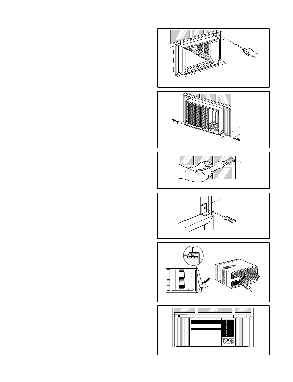
5. Pull each Frame curtain fully to each window sash
track, and pull the bottom window sash down behind
the Top retainer bar until it meets.
6. Attach each Frame curtain the window sash by using
screws (Type C). (See Fig. 29)
7. Slide the unit into the cabinet. (See Fig. 30)
CAUTION: For security purpose, reinstall screws (Type
A) at cabinet's sides.
8. Cut the Foam-strip to the proper length and insert
between the upper window sash and the lower
window sash. (See Fig. 31)
9. Attach the Window locking bracket with a screw
(Type C). (See Fig. 32)
10. Attach the front grille to the cabinet by inserting the
tabs on the grille into the tabs on the front of the
cabinet. Push the grille in until it snaps into place.
(See Fig.33)
NOTE: Please refer p.5 for setting ventilation kit.
11. Lift the inlet grille and secure it with a screw (Type A)
through the front grille. (See Fig. 33)
12. Window installation of room air conditioner is now
completed.
Power Cord
Screw (Type A)
Screw
Window locking
bracket
Foam-Strip
Screw(Type C)
Figure 29
Figure 30
Figure 31
Figure 32
Figure 33
Figure 34
Page 19

—19—
4. TROUBLESHOOTING GUIDE
4.1 OUTSIDE DIMENSIONS
3023/32 (770)
26(660)
16
27
/32 (428)
CAPILLARY TUBE
COMPRESSOR
BLOWER
EVAPORATOR COIL
CONDENSER COIL
FAN
MOTOR
4.2 PIPING SYSTEM
Following is a brief description of the important components and their functions in the refrigeration system.
Refer to Fig. 35 to follow the refrigeration cycle and the flow of the refrigerant in the cooling cycle.
MOTOR
COMPRESSOR
OIL
(LIQUID REFRIGERANT)
CAPILLARY TUBE
OUTSIDE COOLING
AIR FOR REFRIGERANT
PASS THROUGH
SUCTION LIME
COOL LOW PRESSURE VAPOR
COOLED
AIR
COMPLETE LIQUID
BOIL OFF POINT
LIQUID
PRESSURE
DROP
ROOM AIR HEAT LOAD
VAPOR INLET
HOT
DISCHARGED
AIR
LIQUID OUTLET
HIGH PRESSURE VAPOR
LIQUID PEFRIGERANT
LOW PRESSURE VAPOR
ROOM AIR CONDITIONER
EVAPORATOR COILS CONDENSER COILS
CYCLE OF REFRIGERATION
Figure 35
Page 20

—20—
4.3 TROUBLESHOOTING GUIDE
In general, possible trouble is classified in two causes.
The one is called Starting Failure which is caused from an electrical defect, and the other is Ineffective Air
Conditioning caused by a defect in the refrigeration circuit and improper application.
Unit runs but poor cooling
Ineffective Cooling
Check of outdoor coil
(heat exchanger) & the fan
operation.
Check gas leakage.
Repair gas leak.
Replacement of unit if the
unit is beyond repair.
Satisfactory operation with
temperature difference of
inlet & outlet air ; 44.6~50°F
Check heat load increase.
Unexpected residue
Overloaded Circuit
Check of inside gas
pressure.
Adjusting of refrigerant
charge
Malfunction of compressor
Replacement of
compressor
Check of cold air circulation
for smooth flow.
Dirty indoor coil
(Heat exchanger)
Malfunction of fan
Clogged of air filter
Obstruction at air outlet
Correct above trouble
Stop of auto air-swing
Check clogging in
refrigeration circuit.
Repair clogging in
refrigeration circuit.
Page 21

—21—
Fails to Start
Check of circuit breaker
and fuse.
Gas leakage of feeler bulb
of thermostat
Check of control switch.
Only fan fails to start.
Improper wiring.
Defect of fan motor
capacitor.
Irregular motor resistance
( ).
Irregular motor insulation
( ).
Replacement of fan motor
Regular but fails to start
Replacement of compressor
(locking of rotor, metal)
Improper thermostat setting
Loose terminal connection.
Improper wiring
Irregular motor resistance ( )
Irregular motor insulation ( )
Replacement of compressor
(Motor damaged)
Drop of power voltage.
Check capacitor.
Replacement.
Only compressor fails to
start.
Defect of compressor
capacitor.
Check of power source.
Check of control switch
setting.
Page 22

—22——22—
COMPLAINT CAUSE REMEDY
Check voltage at outlet. Correct if none.
Check voltage to rotary switch. If none, check
power supply cord. Replace cord if circuit is open.
Check switch continuity. Refer to wiring diagram
for terminal identification. Replace switch if
defective.
Connect wire. Refer to wiring diagram for terminal
identification. Repair or replace loose terminal.
Test capacitor.
Replace if not within ±10% of manufacturer's
rating. Replace if shorted, open, or damaged.
Fan blade hitting shroud or blower wheel hitting
scroll. Realign assembly.
Units using slinger ring condenser fans must
have 1/4to 5/16inch clearance to the base. If it is
hitting the base, shim up the bottom of the fan
motor with mounting screw(s).
Check fan motor bearings; if motor shaft will not
rotate, replace the motor.
Check voltage. See limits on this page. If not within
limits, call an electrician.
Test capacitor.
Check bearings. Does the fan blade rotate freely?
If not, replace fan motor.
Pay attention to any change from high speed to
low speed. If the speed does not change, replace
the motor.
Check grommets; if worn or missing, replace them.
If cracked, out of balance, or partially missing,
replace it.
If cracked, out of balance, or partially missing,
replace it.
Tighten it.
If knocking sounds continue when running or
loose, replace the motor. If the motor hums or
noise appears to be internal while running,
replace motor.
No power
Power supply cord
Rotary switch
Wire disconnected or
connection loose
Capacitor (Discharge
capacitor before testing.)
Will not rotate
Revolves on overload.
Grommets
Fan
Blower
Loose set screw
Worn bearings
Fan motor will not run.
Fan motor runs
intermittently
Fan motor noise.
Page 23

—23—
COMPLAINT CAUSE REMEDY
Check voltage. See the limits on the preceding.
page. If not within limits, call an electrician.
Check the wire connections, if loose, repair or
replace the terminal. If wires are off, refer to wiring
diagram for identification, and replace. Check wire
locations. If not per wiring diagram, correct.
Check for continuity, refer to the wiring diagram
for terminal identification. Replace the switch if
circuit is open.
Check the position of knob If not at the coldest
setting, advance the knob to this setting and
restart unit.
Check continuity of the thermostat. Replace
thermostat if circuit is open.
Check the capacitor.
Replace if not within ±10% of manufacturers
rating. Replace if shorted, open, or damaged.
Check the compressor for open circuit or
ground. If open or grounded, replace the
compressor.
Check the compressor overload, if externally
mounted. Replace if open. (If the compressor
temperature is high, remove the overload, cool it,
and retest.)
Check the voltage. See the limits on the preceding page. If not within limits, call an electrician.
Check overload, if externally mounted.
Replace if open. (If the compressor temperature
is high, remove the overload, cool, and retest.)
If not running, determine the cause. Replace if
required.
Remove the cabinet. inspect the interior surface
of the condenser; if restricted, clean carefully
with a vacuum cleaner (do not damage fins) or
brush. Clean the interior base before
reassembling.
If condenser fins are closed over a large area
on the coil surface, head pressures will increase,
causing the compressor to cycle. Straighten the
fins or replace the coil.
Voltage
Wiring
Rotary
Thermostat
Capacitor (Discharge
capacitor before
servicing.)
Compressor
Overload
Voltage
Overload
Fan motor
Condenser air flow
restriction
Condenser fins
(damaged)
Compressor will not run,
but fan motor runs.
Compressor cycles
on overload.
Page 24

—24—
COMPLAINT CAUSE
REMEDY
Test capacitor.
Check the terminals. If loose, repair or replace.
Check the system for a restriction.
If restricted, clean of replace.
Close if open.
Determine if the unit is properly sized for the area to
be cooled.
Check the set screw or clamp. If loose or missing,
correct. If the blower or fan is hitting air guide,
rearrange the air handling parts.
Remove the cabinet and carefully rearrange tubing
not to contact cabinet, compressor, shroud, and
barrier.
Set the knob to HIGH COOL or LOW COOL while
rocker switch is ON.
Check terminals. If loose, repair or replace.
Check the synchronous motor for open circuit.
Capacitor
Wiring
Refrigerating system
Air filter
Exhaust damper door
Unit undersized
Blower or fan
Copper tubing
Rotary switch.
Wiring
Synchronous motor.
Compressor cycles
on overload.
Insufficient cooling or
heating
Excessive noise.
Auto air-swing fails.
Page 25

—25—
5. SCHEMATIC DIAGRAM
5.1 CIRCUIT DIAGRAM
• MODEL : HQ-2243TH
1
3
4
7
2
6
5
WIRING DIACRAM
ROCKER SWITCH
WH
WH
SYNC. M.
POWER INPUT
WH(BL)BK(BR)
(Ribbed)
(Plain)
NO.
1 POWER CORD 1
2 ROTARY SWITCH 1
3 FAN MOTOR 1
4 CAPACITOR 1
5 THERMOSTAT 1
6 COMPRESSOR 1
7 SYNCHRONOUS MOTOR 1
Q'TY PER SET
DESCRIPTION
Page 26
—26—
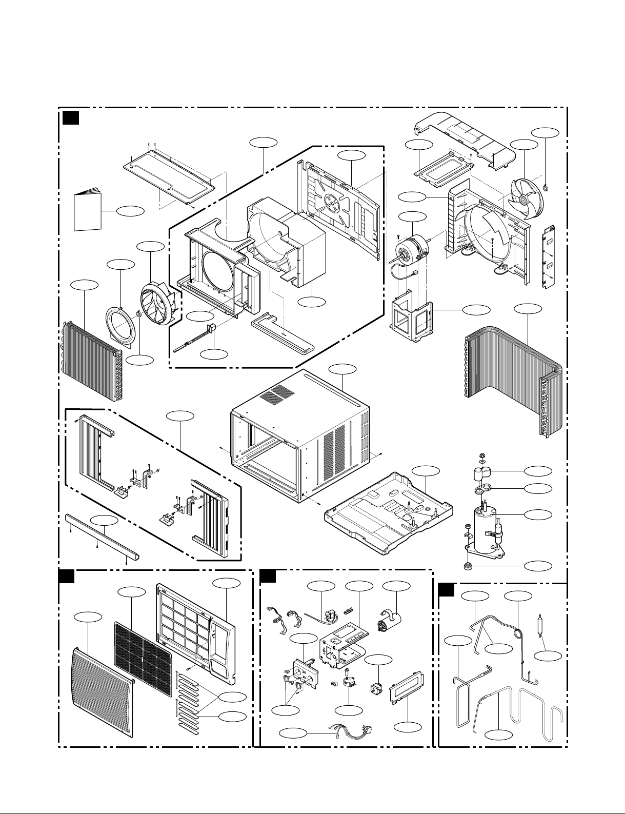
6. EXPLODED VIEW
• MODEL: HQ-2243TH,LWC081
11
4
4
5
3
2
6
1
13
5
9
6
14
17
19
23
24
1
6 1 4
7
8
2
1
9
3
4
3
2
5
3
2
5
18
12
15
16
20
7
10
16
8
22
O
wner's M
anual
A
C
B
D
21
Page 27

—27—
7. REPLACEMENT PARTS LIST
• MODEL: HQ-2243TH
PART NO.
DESCRIPTION
REMARK
A FRONT GRILLE ASS'Y CW353110189B R
1 GRILLE, FRONT CW353010138A
2 INLET, GRILLE CW353010139A
3 AIR FILTER ASS'Y CW5231R6159F
4 HORIZONTAL LOUVER CW4758R7264J
5 HORIZONTAL LOUVER CW4758R7278J
B COMP&ACCESSORY ASS'Y
1 ANTI-VIBRATION BUSH CW4022-L005A
2 COMPRESSOR CW2520HFK2CA R
3 GASKET CW4986-L004A
4 TERMINAL COVER CW355030048C
5 BASE PAN WELD ASS'Y CW304110010F
6 BARRIER, SINGLE CW479010036A
7 SCROLL CW307220009A
8 AIR GUIDE ASSEMBLY CW523920001V
9 CABINET ASS'Y CW3091R6056A
10 DAMPER ASS'Y CW4900R7265A
11 MOUNT, MOTOR CW4960R2895B
12 MOTOR ASSEMBLY, SINGLE CW468120011L R
13 SHROUD CW4998R1602A
14 FAN, TURBO CW590120009A R
15 FAN, AXIAL CW5900R1330B R
16 CLAMP, SPRING CW3H02932C
17 ORIFICE CW494820014A
18 BRACE CW4800R7271A
19 EVAPORATOR ASSEMBLY, FIRST CW542120017N
20 CONDENSER ASSEMBLY, FIRST CW540320032F
21 VERTICAL LOUVER CW4758R6157A
22 OPERATING INSTRUCTION CW382820046H
23 INSTALLATION KIT CW3127R3403U R
24 UPPER GUIDE CW2H00858D
C CONTROL BOX ASSEMBLY CW499520088N
1 CONTROL BOX , SINGLE CW4994R1587A
2 CONTROL PANEL CW372120058J
3 KNOB ASS'Y CW494130001M
4 CAPACITOR CW6120R2194P R
5 POWER CORD ASS'Y CW2H00677U R
6 THERMOSTAT CW2H01109L R
7 COVER CW355130001A
8 ROTARY, SWITCH CW2H00598E R
9 MOTOR ASSY, SYNC CW2H01102A R
D PIPE
1 TUBE ASSEMBLY, SUCTION INDOOR CW521110094B
2 TUBE ASSEMBLY, DISCHARGE SINGLE CW521130325D
3 TUBE ASSEMBLY, EVAPORATOR CW521030144U
4 TUBE ASSEMBLY, EVAPORATOR CW521030144V
5 TUBE, CAPILLARY BEND CW521130296E
6 DRIER ASSEMBLY CW585130001K
LOCATION
NO.
R: RECOMMANDABLE PARTS.
Page 28

September, 2003
P/No.: 3828A20163N Printed in Korea
 Loading...