

Page 1
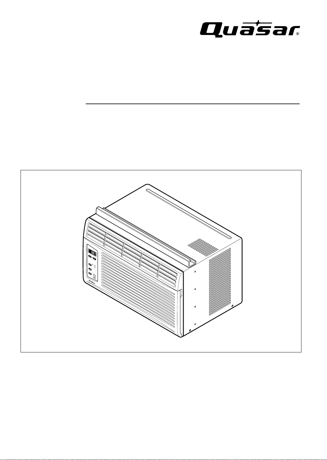
INSTALLATION AND
OPERATING INSTRUCTIONS
Room Air Conditioner
Model: HQ-2052UH
Please read these operating instructions thoroughly
before using your air conditioner and keep for future
reference.
For assistance, please call: 1-800-211-PANA(7262) or
Register your product at : http://www.panasonic.com/register
CW382820391E
Page 2
About the Controls on the Air Conditioner
Features and Installation
Before you call for service...
2
Safety Precautions
FOR YOUR RECORDS
Write the model and serial numbers here:
Model #
Serial #
You can find them on a label on the side of the unit.
Dealer's Name
Date Purchased
Staple your receipt here for proof of purchase.
Inside you will find many helpful hints on how to use and
maintain your air conditioner properly. Just a little preventive
care on your part can save you a great deal of time and
money over the life of your air conditioner.
You'll find many answers to common problems in the chart
of troubleshooting tips. If you review our chart of
Troubleshooting Tips first, you may not need to call for
service at all.
READ THIS MANUAL
CAUTION
• Contact an Authorized Service Center for repair or
maintenance of this unit.
• The air conditioner is not intended for use by young
children or invalids without supervision.
• Young children should be supervised to ensure that
they do not play with the air conditioner.
Safety Precautions
Safety Precautions.............3
About the Controls
on the Air Conditioner
Controls..............................5
Air direction........................7
Care and Maintenance ......7
Features
and Installation
Features.............................8
Window Requirements.......9
Electrical Data..................11
Before You Call
For Service...
Normal Operation.............12
Abnormal Operation.........12
Page 3
WARNING
3
Safety Precautions
Safety Precautions
To prevent injury to the user or other people and property damage, the following instructions must be followed:
■ Incorrect operation will cause harm or damage. The seriousness is classified by the following indications.
■ Because of the weight of the product, it is recommended that you have a helper to assist in the installation.
■ Use Caution! Sharp Edges! See Warning, page 4.
WARNING : This symbol indicates the possibility of death or serious injury.
CAUTION
:
This symbol indicates the possibility of injury or damage to
property
■ Meanings of symbols used in this manual are as shown below.
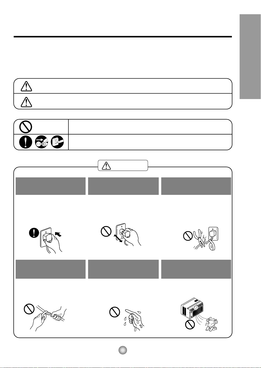
Be sure not do this.
Be sure to follow the instructions.
Plug in the power plug
properly.
• Otherwise, it will cause electric
shock or fire due to heat
generation.
Do not operate or stop the
unit by inserting or pulling
out the power plug.
• It will cause electric shock or fire
due to heat generation.
Do not damage or use an
unspecified power cord.
• It will cause electric shock or fire.
•
If the power cord is damaged, it must
be replaced by the manufacturer or
its service agent or a similarly
qualified person in order to avoid a
hazard.
Do not modify the length of
the power cord or use an
extension cord.
• It will cause electric shock or fire
due to heat generation.
Do not operate with wet
hands or in damp
environment.
• It will cause electric shock.
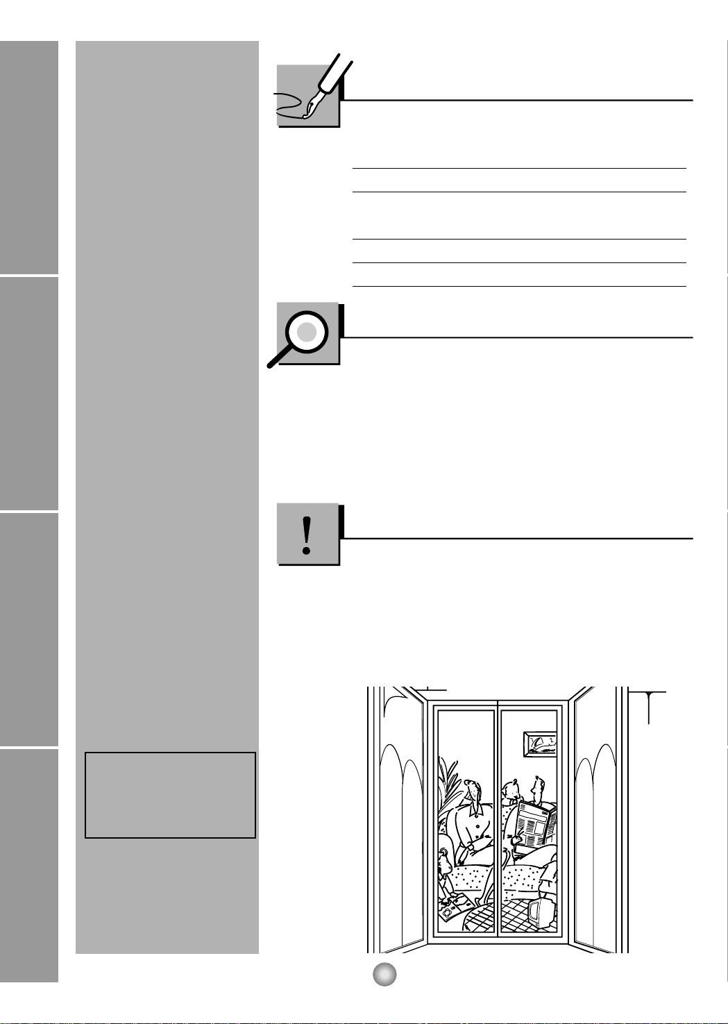
Do not direct air flow at room
occupants.
• This could lead to health
problems.
Page 4
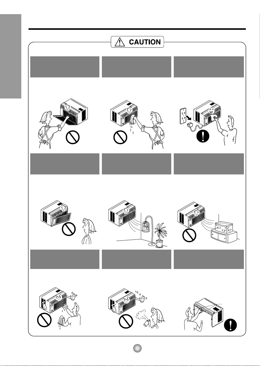
Sharp edges
When the air filter is to be
removed, do not touch the
metal parts of the unit.
• They are sharp and may cause
an injury.
Do not clean the air
conditioner with water.
• Water may enter the unit and
degrade the insulation. It may
causeanelectricshock.
Whentheunitistobe
cleaned, switch the unit off,
and unplug it.
• Since the fan rotates at high
speed during operation, it may
cause an injury.
Do not operate the unit
without the air filter or when
the front intake grille has
been removed.
• It could cause dust to
accumulate on the heat
exchanger.
Do not put a pet or house
plant where it will be
exposed to direct air flow.
• This could injure the pets
or plants.
Do not use the unit for any
other purpose than its
intended use.
• Do not use this air conditioner to
preserve precision devices, food,
pets, plants, or art objects.
It may cause deterioration of
quality, etc.
Do not operate switches
with wet hands
.
• It may cause an electric shock.
Do not apply an insecticide
or flammable spray.
• It may cause a fire or damage of
the cabinet.
SHARP EDGES!
• Use caution when handling the
case. Grip it firmly and do not allow
it to slip while holding it.
• Use heavy gloves to handle the
case if necessary.
4
Safety Precautions
Page 5

5
About the Controls on the Air Conditioner
About the Controls on the air conditioner
The controls will look like the following.
Controls
TEMPERATURE SETTING
MODE
ECONOMY, FAN and DRY.
• Every time you push this button it is set as follows.
{High(F2) → Low(F1) → High(F2)...}.
is
DRY
• When this unit is in dry mode, the fan rotates at low speed.
The fan stops when the compressor stops cooling.
Approximately every 3 minutes the fan will turn on and the
unit checks the room air temperature to set itself.
• This button can automatically control the temperature
of the room. The temperature can be set within a range of
60°F (16°C) to 86°F (30°C) by 1°F (1°C).
Select the lower number for lower temperature of the room.
°F
hr
Page 6

6
About the Controls on the Air Conditioner
Remote controller
Precaution:
The Remote Controller will not function properly if strong light strikes the sensor window of the
air conditioner or if there are obstacles between the Remote Controller and the air conditioner.
1. Remove the cover from the back of the remote
controller
2. Insert two batteries.
• Be sure that the (+) and (-) directions are correct.
• Be sure that both batteries are new.
3. Re-attach the cover.
• Do not use rechargeable
batteries. Such batteries
differ from standard dry
cells in shape, dimensions,
and performance.
• Remove the batteries from
the remote controller if the
air conditioner is not going
to be used for an extended
length of time.
How to Insert Batteries
OPERATION
TEMP
TIMER
MODE
ECONOMY
FAN SPEED
ROOM TEMPERATURE SETTING BUTTON
ECONOMY
ON/OFF TIMER BUTTON
OPERATION BUTTON
FAN SPEED SELECTION BUTTONS
OPERATION MODE SELECTION BUTTON
• To turn the air conditioner ON, push the button. To turn the air conditioner OFF, push the button again.
• This button takes priority over any other buttons.
• When you first turn it on, the air conditioner is on the High cool mode and the temp. at 72°F (22°C).
Every time you push this button, it will toggle between COOL, ECONOMY, FAN
and DRY.
• If you push this button, the fan stops when the compressor stops
cooling. Approximately every 3 minutes the fan will turn on and check
the room air to determine if cooling is needed.
• You can set the time when the unit will turn on or turn off automatically by pressing the timer
button. If the unit is in operation, this button controls the time it will be turned off. If the unit is
in off state, this button controls the time it will start. Every time you push this button, the
remaining time will be set as follows:
- STOPPING OPERATION
• Every time you push this button, when the air conditioner is operating, timer is set as
follows : (1Hour
→
2Hours → 3Hours → 4Hours → 5Hours → 6Hours → 7Hours →
8Hours
→
9Hours → 10Hours → 11Hours → 12Hours → 0Hour → 1Hour → 2Hours → ...)
• The Setting Temperature will be raised by 2°F (1°C) 30 min. later and by 2°F (1°C) after
another 30 min.
- STARTING OPERATION
• Every time you push this button, when the air conditioner is not operating, timer is set as
follows : (1Hour
→
2Hours → 3Hours → 4Hours → 5Hours → 6Hours → 7Hours →
8Hours
→
9Hours →10Hours → 11Hours → 12Hours → 0Hour → 1Hour → 2Hours → ...)
Every time you push this button, it is set as follows.
{High(F2)
→
Low(F1) → High(F2)...}.
This button can automatically control the temperature of the room. The temperature
can be set within a range of 60°F to 86°F by 1°F. (16°C to 30°C by 1°C)
Select the lower number for lower temperature of the room.
Page 7

7
About the Controls on the Air Conditioner
TURN THE AIR CONDITIONER OFF AND REMOVE THE PLUG FROM THE POWER OUTLET.
• TO CLEAN FILTER
The air filter will become dirty as it removes
dust from the inside air.
It should be washed at least every 2 weeks.
If the air filter remains full of dust, the air
flow will decrease and the cooling capacity
will be reduced, possibly damaging the unit.
1. Pull the inlet grille forward and pull out the
air filter. (Fig. 1)
2. Wash the air filter in warm 104°F(40°C) water.
Be sure to shake off all the water before
replacing the filter.
• CLEANING THE AIR CONDITIONER
The front grille and inlet grille may be wiped with a
cloth dampened in a mild detergent solution. (Fig. 2)
The cabinet may be washed with mild soap or
detergent and lukewarm water, then polished with
a liquid wax used for appliances.
To ensure continued peak efficiency, the condenser
coils (outside of unit) should be checked
periodically and cleaned if clogged with soot or
dirt from the atmosphere.
• HOW TO REMOVE THE FRONT GRILLE
1. Pull the inlet grille forward.
2. Remove the screw securing the front grille. (Fig. 3)
3. Push the grille up from the bottom and pull
the top of the grille away from the case as
the top tabs lift out of their slots. (Fig. 4)
Do not force open
or open too
far (about 56°)
Fig. 1
Fig. 2
Fig. 3
Fig. 4
Additional controls and important information.
Care and Maintenance
Air Direction
• ADJUSTING THE AIR DIRECTION USING THE HORIZONTAL AIR-DEFLECTOR CONTROL
Using the control tabs, the air flow can be directed
to the left, right, straight ahead, or any combination
of these directions.
Page 8

8
Features and Installation
1
8
5
3
2
6
7
9
4
10
Wire net
Groove
Learning parts name prior to installation will help you understand the installation procedure.
Features
1. CABINET
2. HORIZONTAL AIR DEFLECTOR
3. COOL AIR DISCHARGE
4. FRONT GRILLE
5. INLET GRILLE
6. AIR FILTER
7. CONTROL BOARD
8. AIR INTAKE
9. UPPER GUIDE
10. REMOTE CONTROLLER
■ How to install wire net on the back side of the cabinet
(Optional : CW353020031B)
Insert the rear grill wire ends into the 4 respective slots provided along the groove at the back of unit
Features and Installation
Page 9

9
Features and Installation
OUTDOORSINDOORS
INNER
SILL
OUTER
SILL
INNER
SILL
WOOD STRIP MOUNTED
ON TOP OF INNER SILL
1"
WOOD STRIP
FOR
L
BRACKET
3
/4"
CLEARANCE
STORM
WINDOW
FRAME
OUTDOORSINDOORS
OUTER
SILL
TYPE B: Qty:5
(WOOD SCREW)
HARDWARE
TYPE A: Qty:11
(SHORT SCREW)
TYPE C: Qty:3
(L BRACKET)
TYPE E: Qty:1
(SASH SEAL)
(Not adhesive backed)
TYPE D: Qty:1
(SEAL STRIP)
(Adhesive backed)
TYPE F: Qty:2
(GUIDE PANEL)
TYPE G: Qty:1
(SUPPORT BRACKET)
25/64"
(10mm)
5/8"
(16mm)
DRAIN PIPE
Qty:1
NOTE: All supporting parts should be secured to firm wood, masonry, or metal.
1. This unit is designed for installation in standard double hung windows with actual opening widths of
22" to 36". The upper and lower sash must open sufficiently to allow a clear vertical opening of 13"
from the bottom of the sash to the window stool.
2.If a storm window presents interference, fasten a 2" wide wood strip to the inner window sill across
the full width of the sill. The wood strip should be thick enough to raise the height of the window sill
so that the unit can be installed without interference by the storm window frame.
See Fig. 5-2. The top of the wood strip should be approximately
3
/4" higher than the storm window
frame (STORM WINDOW FRAME) or wood strip (OUTDOORS) to help condensation to drain
properly to the outside.
3. Install a second wood strip (approximately 18" long by 1
1
/2" wide and same thickness as first strip)
in the center of the outer sill flush against the back off the inner sill. This will raise the L bracket as
shown in Fig. 5-2.
4. The thickness of the second wood strip may not be the same as the first wood strip.
The thickness of the second wood strip must be defined to keep the
3
/4 inch distance between the
inner sill or the top of the first wood strip and the outer sill.
Window Requirements
Installation
Fig. 5-1
Fig. 5-2
Page 10

10
Features and Installation
ROOM SIDE
CENTER LINE
INNER SILL
SEAL STRIP
(TYPE D)
CENTER LINE
OUTSIDE
INSIDE
L
BRACKET
OUTER SILL
INNER SILL
TYPE A
8"
8"
CENTER LINE
SEAL
WINDOW FRAME
BOTTOM
GUIDE
ABOUT
1/4"
L
BRACKET
UPPER GUIDE
TYPE A
TYPE A
A. BEFORE INSTALLATION
1. Insert the guide panels into the guides of the air
conditioner. Fasten the curtains to the unit with
screws (TYPE A), as shown Fig. 6.
2. Cut the adhesive-backed seal strip (TYPE D) to the
window width.
Remove the backing from the seal strip and attach
the seal strip to the underside of the bottom
window. (Fig. 7)
B. NOW START INSTALLATION
1. LOCATING UNIT IN A WINDOW
Open the window and mark center line on the
center of the inner sill, as shown in Fig. 8.
2. ATTACH L BRACKET
a. Install the L brackets behind the inner window
sill, with short side of bracket as shown. Use the
2 screws (TYPE A) provided.
b. The bracket helps to hold the unit securely in
place. Be sure to place bracket edge flush
against back of inner sill. See Fig. 9.
3. INSTALL THE AIR CONDITIONER IN THE
WINDOW
a. Carefully lift the air conditioner and slide it into
the open window. Make sure the bottom guide of
the air conditioner drops into the notches of the
L bracket. See Fig. 9.
IMPORTANT :
When the air conditioner drops into the L bracket, the
air conditioner will be centered in window opening as
shown in Fig. 10.
b.While steadying the air conditioner, carefully
bring the window sash down behind the upper
guide of the air conditioner, as shown in Fig. 11.
Fig. 6
Fig. 7
Fig. 8
Fig. 9
Fig. 10
Fig. 11
During the following step, hold unit firmly until
window sash is lowered to top channel behind
side panel frames. Personal injury or property
damage may result if unit falls from window.
CAUTION
Page 11

11
Features and Installation
Do not under any
circumstances cut
or remove the
grounding prong
from the plug.
Line Cord Plug Use Wall Receptacle Power Supply
Power supply cord with
3-prong grounding plug
Standard 125V, 3-wire grounding
receptacle rated 15A, 125V AC
Use 15 AMP, time
delay fuse or circuit
breaker.
SASH SEAL
(TYPE E)
L BRACKET
TYPE A
DRAIN PIPE
DRAIN CAP
TYPE B
Support Bracket (TYPE G)
Fig. 12
Fig. 13
Fig. 14
4. SECURE THE GUIDE PANELS
Extend the guide panels (TYPE F) to fill the window
opening using 4 screws (TYPE B) to secure them, as
shown in Fig. 12.
5. INSTALL THE SASH SEAL AND SASH LOCK
a. Cut the sash seal (TYPE E) to the window width.
Stuff the sash seal between the glass and the
window to prevent air and insects from getting into
the room, as shown in Fig. 12.
b. Fasten the L bracket using a screw (TYPE A), as
showninFig.12.
6. a. Remove the screws that secure the cabinet and
base pan in the right side.
b.
Fasten the support bracket (TYPE G) using a
removed screw. Attach the support bracket (TYPE G)
in the inner window sill with a screw (TYPE B), as
shown Fig. 13.
7. Window installation of room air conditioner is now
completed. See ELECTRICAL DATA for attaching
power cord to electrical outlet.
C. HOW TO SECURE THE DRAIN PIPE
In humid weather, excess water may cause the BASE
PAN to overflow. To drain the water, remove the
DRAIN CAP and secure the DRAIN PIPE to the rear
hole of the BASE PAN. (Fig. 14) Press the drain pipe
into the hole by pushing down and away from the fins
to avoid injury.
REMOVAL FROM WINDOW
Turn the air conditioner off, disconnect the power cord, remove the Support Bracket, L bracket and the screws
installed through the top and bottom of the guide panels, and save for reinstallation later. Close the guide panels.
Keeping a firm grip on the air conditioner, raise the sash, and carefully tilt the air conditioner backward, draining
any condensate. Lift the air conditioner from the window and remove the sash seal from between the windows.
USE OF EXTENSION CORDS
Because of potential safety hazards, we strongly discourage the use of an extension cord. However, if you wish to
use an extension cord, use a CSA certified/UL-listed 3-wire (grounding) extension cord, rated 15A, 125V.
Electrical Data
Hang Push
TYPE B
Page 12

12
Before you call for service...
Before you call for service...
Troubleshooting Tips save time and money!
Review the chart below first and you may not need to call for service.
Normal Operation
• You may hear a pinging noise caused by water being picked up and thrown against the condenser
on rainy days or when the humidity is high. This design feature helps remove moisture and improve
efficiency.
• You may hear the relay click when the compressor cycles on and off.
• Water will collect in the base pan during high humidity or on rainy days. The water may overflow
and drip from the outdoor side of the unit.
• The fan may run even when the compressor does not.
Abnormal Operation
Problem Possible Causes What To Do
■ The air conditioner is
unplugged.
■ Thefuseisblown/circuit
breaker is tripped.
■ Power failure.
■ Airflow is restricted.
■ TEMP Control set to a
higher number.
■ The air filter is dirty.
■ The room may have been
hot.
■ Cold air is escaping.
■ Cooling coils have iced up.
■ Ice blocks the air flow and
stops the air conditioner
from cooling the room.
• Make sure the air conditioner plug is pushed
completely into the outlet.
• Check the house fuse/circuit breaker box and
replace the fuse or reset the breaker.
• When power is restored, wait 3 minutes to restart the
air conditioner to prevent tripping of the compressor
overload.
• Make sure there are no curtains, blinds, or furniture
blocking the front of the air conditioner.
• Set the TEMP Control to a lower number.
• Clean the filter at least every 2 weeks.
See the operating instructions section.
• When the air conditioner is first turned on
youneedtoallowtimefortheroomtocooldown.
• Check for open furnace floor registers
and cold air returns.
• Set the air conditioner's vent to the closed position.
• See Air Conditioner Freezing Up below.
• Set the mode control at High Fan or High Cool with
thehightemperature.
Air conditioner
does not start
Air conditioner
does not cool as it
should
Air conditioner
freezing up
Page 13

Panasonic Room Air Conditioner
Limited W arranty
Panasonic Consumer Electronics Company or Panasonic Sales Company (collectively referred to as "the Warrantor") will repair
this product with new or refurbished parts in case of defects in material or workmanship, free of charge, in the USA or Puerto
Rico in accordance to the following (All time periods start from the date of the original purchase).
SEALED REFRIGERATING SYSTEM (compressor and interconnecting tube): FIVE (5) YEARS - PARTS AND LABOR
ALL OTHER COMPONENTS: ONE (1) YEAR - PARTS AND LABOR
In-home service in the USA can be obtained during the warranty period by contacting a Panasonic Service Company (PASC)
Factory Servicenter listed in the Servicenter Directory. Or call toll free, 1-800-211-PANA(7262), to locate a PASC authorized
Servicenter. In-home service in Puerto Rico can be obtained during the warranty period by calling the Panasonic Sales Company
telephone number listed in the Servicenter Directory.
Note: If the unit is installed at the other than normal window height and/or has been
custom-installed (e.g., through the wall), the customer is responsible for removing
the unit from its installation prior to the performance of in-home service.
This warranty is extended only to the original purchaser. A purchase receipt or other proof of date of the original purchase is
required for service and parts replacement under this warranty.
This warranty only covers failures due to defects in materials and workmanship and does not cover normal wear or cosmetic
damage. The warranty does not cover damages which occur in shipment, or failures which are caused by products not supplied by
the warrantor, or failures which result from accident, misuse, abuse, neglect, mishandling, misapplication, faulty installation,
maladjustment of customer controls, improper maintenance, alteration, modification, power line surge, lightning damage,
improper voltage supply, commercial use such as hotel, office, restaurant, or other business or rental use of the product, or service
by anyone other than a PASC Factory Servicenter or a PASC authorized Servicenter, or damage that is attributable to acts of God.
LIMITS AND EXCLUSIONS
There are no express warranties except as listed above.
THE WARRANTOR SHALL NOT BE LIABLE FOR INCIDENTAL OR CONSEQUENTIAL DAMAGES RESULTING
FROM THE USE OF THIS PRODUCT, OR ARISING OUT OF ANY BREACH OF THIS WARRANTY ALL EXPRESS AND
IMPLIED WARRANTIES, INCLUDING THE WARRANTIES OF MERCHANTABILITY, ARE LIMITED TO THE
APPLICABLE WARRANTY PERIOD SET FORTH ABOVE.
Some states do not allow the exclusion or limitation of incidental or consequential damages or limitations on how long an
implied warranty lasts, so the above exclusions or limitations may not apply to you.
This warranty gives you specific legal rights and you may also have other rights which vary from state to state If a problem with
this product develops during or after the warranty period, you may contact your dealer or Servicenter If the problem is not
handled to your satisfaction, then write to the Consumer Affairs Department at the company address indicated above
SERVICE CALLS WHICH DO NOT INVOLVE DEFECTIVE MATERIALS OR WORKMANSHIP AS DETERMINED BY
THE WARRANTOR, IN ITS SOLE DISCRETION, ARE NOT COVERED COSTS OF SUCH SERVICE CALLS ARE THE
RESPONSIBILITY OF THE PURCHASER.
[For assistance, please call: 1-800-21 1-PANA (7262) or send e-mail to consumerproducts@panasonic.com]
Printed in Korea
Panasonic Consumer Electronics Company,
Division of Matsushita Electric Corporation
of America
One Panasonic Way
Secaucus, New Jersey 07094
Panasonic Sales Company,
Division of Matsushita Electric of Puerto Rico, Inc.,
Ave. 65 de Infanteria, Km. 9.5
San Gabriel Industrial Park
Carolina, Puerto Rico 00985
 Loading...