

Page 1

QUASAR CODE # 3126 - SOUND ACTIVATED RELAY SWITCH
General Guidelines for Electronic Kits and Assembled Modules
Thank you for choosing one of our products. Please take some time to carefully read the important
information below concerning use of this product. The assembly and operating instructions are on the
following pages. Help with component identification can be found on our website at
www.quasarelectronics.co.uk/componentid.htm. If you are unsure about any aspect of the assembly or use of
this product please contact our Support Team before proceeding.
WEEE Directive (Waste Electrical and Electronic Equipment)
Notice To All European Union Citizens. Important environmental information
about this product.
The crossed out wheeled bin symbol on this product, package or documentation
indicates that disposal of this product after its lifecycle could harm the environment.
Do not dispose of this product (or batteries if used) as unsorted municipal waste. It
should be disposed by a specialized company for recycling.
The unit should be returned to your distributor or to a local recycling service. Please
respect the local environmental rules. If in doubt contact your local authorities about
waste disposal rules.
Safety: General rules concerning safe use of our Kits or Modules.
To ensure your safety, please observe these safety measures. In no way are these complete. As safety
requirements vary, please check with your local authorities, in order to comply with local requirements.
If in doubt, seek the help of a qualified person.
Battery or wall-adaptor operated devices are safe devices. They do not require special attention unless
mains voltage is connected to an output e.g. a relay.
To ensure electrical safety, and also protection from fire or personal injury, make sure your mains
operated equipment complies with these safety hints:
Use a suitable plastic enclosure. If a metal enclosure is used, make sure it is properly earthed.
Use a power switch if the device consumes more than 10W. Use a double pole switch for mains
operated, transformer-less kits.
Mount a fuse in series with the mains switch. Use a slow blow (T) 50mA fuse for transformers up to
10W and a 100mA fuse for transformers up to 20W.
Use a mains input connector, or a robust power cord with a clamp.
Internal wiring carrying mains voltages must have a minimum cross-sectional area of 0.5mm2.
If supplied, attach the power rating label near the power cord of the device and fill-out the mains voltage,
frequency, power consumption and fuse values.
Troubleshooting and Support
90% of non working kits are due to poor soldering.
We operate a Get-You-Going service for non-working kits but there is a charge based on the time and
components needed to complete the repair. Quite often it is not economically viable for us to repair and it is
cheaper to supply a new ready made product at full cost.
Disclaimer
Quasar Electronics reserves the right to change product specifications or to discontinue products without
notice. Quasar Electronics cannot be held responsible for any loss or damage, direct or indirect, which might
occur from the use of a product. Quasar Electronics Kits or Modules are intended for educational and
demonstration purposes only. They are not intended for use in commercial applications. If they are used in
such applications the purchaser assumes all responsibility for ensuring compliance with all local laws. In
addition, they are not suitable for use as or as a part of life support systems, or systems that might create a
hazardous situation of any kind.
Page 2
QUASAR CODE # 3126 - SOUND ACTIVATED RELAY SWITCH
The Sound Activated Relay Switch is based on
a circuit published in Silicon Chip magazine,
9/1994, p31. The idea behind a VOX SWITCH
is that instead of the user pressing a switch to
activate a relay, the sound of the users voice
itself activates the relay. This gives hands-free
control over devices like tape recorders.
We have improved the original design by
adding an on-board potentiometer so you can
adjust the trigger sensitivity. The 3126v41
board also features:
1. Screw terminal blocks for all input and
output connections
2. The output is rated to switch up to 120Vac
or 24Vdc @ 1 Amp maximum current. The
relay itself may be rated to switch higher loads
but the PCB tracks limit the amount of current
and voltage that can be safely switched. The
output should NOT be used to switch mains
electricity directly but can instead be used to
switch a higher capacity off-board relay or
switch. The Common (C), Normally
Connected (NC), and Normally Open (NO)
connections are taken to a 3-pole terminal
block on the right hand edge of the board. For
more information please see our relay FAQ
sheet at
www.quasarelectronics.co.uk/pdf/relay-faq.pdf
3. MIC pin spacing increased to make the
MIC body stand off the board. This helps to
reduce a feedback loop that causes the relay to
not turn off (see Note 4 below)
4. “EXT MIC” terminal block input added.
This allows you to mount the supplied
microphone (MIC) away from the board for
convenience or if you are experiencing
feedback that causes the relay to continuously
reactivate or not turn off. Attach using
screened cable no more than 1 metre long. . If
you purchased the pre-assembled version you
will need to carefully unsolder the MIC from
the board first. NOTE: Only use an electret
type MIC as supplied
ASSEMBLY
Check of the components against the Listing.
Follow the overlay for component positions
and orientation. Mount the MIC about 3mm
above board. Note that if the relay is
triggering continuously then it may be
necessary to located the mic some distance
away from the board (like 0.5-1 metre) using
2-core screened cable (not supplied). This
problem is caused by vibration from the relay
itself retriggering the circuit.
Also note that C4 is located under the IC so the
IC socket has to be used. Make sure to get C3
(104) and C4 (101) in their correct places. If
you mix the 101 with the 104 the kit will not
work. Ensure diodes, electrolytic capacitors,
MIC, Q1 and IC1 are inserted with correct
orientation.
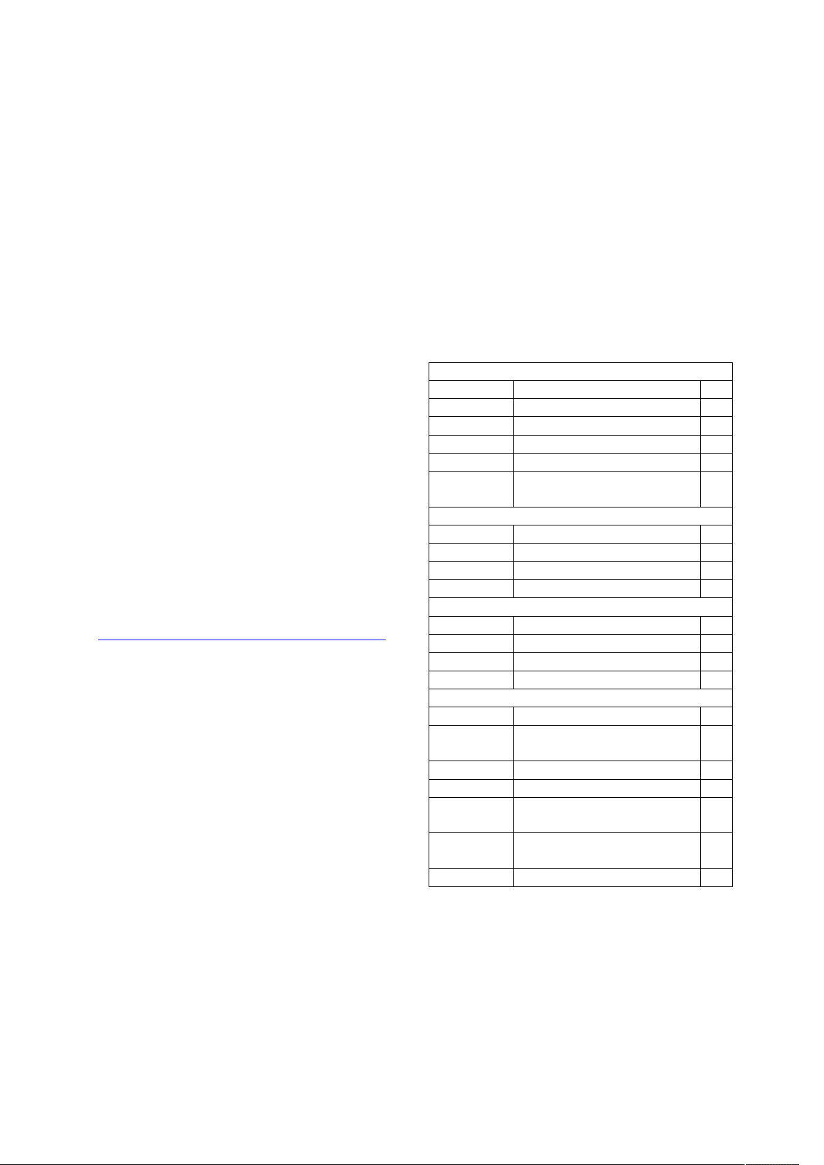
COMPONENTS
Resistors 5%, 1/4W:
R1, R7 1K brown black red 2
R3 2K2 red red red 1
R2, R4, R8 10K brown black orange 3
R9 39K orange white orange 1
R5 1M brown black green 1
R6 200K (204) Koa
potentiometer
Capacitors
C4 100pF (101) monoblock 1
C3 0.1uF (104) monoblock 1
C2, C5 2u2 mini electrolytic cap 2
C1 10u mini electrolytic cap 1
Semiconductors
D1, D4 1N4004 2
D2, D3 1N4148 2
Q1 BC548 1
IC1 LM358 1
Miscellaneous
8 pin IC socket 1
RL1 Relay AZ-SH-112L (or
equivalent)
X1, X2 2 pole terminal block 2
X3 3 pole terminal block 1
L1 3mm LED
MIC Electret microphone
PCB # 3126v41 1
OPERATION
Audio is picked up by the microphone and fed
to the opamp IC1a. This is connected as a noninverting amplifier with a gain of 151 or
+43.6dB. The 100pF capacitor across the 150K
feedback resistor rolls off the high frequency
response above 10kHz to eliminate RF. The
output at pin 1 feeds two diodes, D2 and D3
1
1
1
1
Page 3

QUASAR CODE # 3126 - SOUND ACTIVATED RELAY SWITCH
which function as a half-wave voltage doubler.
These rectify the audio signal to produce a DC
voltage across the 2.2uF ecap, C2 which is
directly proportional to the input audio sound
level.
This DC voltage is fed to pin 5 the second
opamp IC1b. This is connected as a
comparator. A resistive voltage divider applies
about 2V to pin 6. Once the DC voltage across
the 2.2u eCap rises above the voltage at pin 6,
pin 7 pulls high. This turns on transistor Q1
which activates the relay and the LED turns
on. Q1 remains on while the DC voltage at pin
5 is above that at pin 6. Because of the high
opamp gain of IC1a, and with the voltage
doubler gain the circuit has a fast response
time. However, the release time takes about 3
seconds determined by the time constant of
C2, R5 (the 1M resistor) and the pin 6
threshold voltage. D1 across the relay coil
protects Q1 from back-emf when the relay
turns off.
Power the board using a 9-12Vdc battery or for
extended periods a mains adaptor like our
660.446UK. D4 acts as protection for the
circuit in case power is connected the wrong
way. Current drain when off is 5-7mA. It is
SCHEMATIC
about 35mA when activated. Sensitivity may
be varied with the 200K Koa potentiometer. A
good working VOX level is about R6+R9 of
150K. But if you want more sensitivity then
you can reduce R9 to 22K or less and turn the
trimpot R6 to maximum sensitivity (fully
clockwise).
Connect the microphone using 2-core screened
cable up to 1 metre away from the board.
Connect using the EXT MIC terminal block
taking care to observe the MIC polarity (Mpin goes to the case).
The OFF delay time may be adjusted by
varying R3 and R4. Reducing R3 will result in
a longer release time.
You could change the ON duration (governed
by C2 & R5) to say 30 seconds and use the
VOX as a light switch with this delay time
before turning off. Increase C2 to say 10u and
R5 to 3M3.
support@quasarelectronics.co.uk if you have
any questions.
See our full kit and module range at
www.quasarelectronics.co.uk.
Page 4

QUASAR CODE # 3126 - SOUND ACTIVATED RELAY SWITCH
Warning! Risk of Electric Shock!
This information concerns kits and modules with relay outputs. TO USE THE RELAY OUTPUTS
SAFELY YOU MUST OBSERVE THE MAXIMUM VOLTAGE AND CURRENT LIMITS QUOTED
IN THE PRODUCT DOCUMENTATION (this is because the board design may not be rated to
switch the maximum voltage and current limits printed on the relay itself or specified in the relay
manufacturer’s data sheet).
Controlling mains equipment with relay outputs must be treated with extreme caution. Electric
shocks can cause severe and permanent injury or even death. Construction, installation, testing and commissioning
should only be attempted by suitably qualified persons, or under the supervision of a suitably qualified person. These
products are not suitable for children. Before connecting mains powered equipment to the relay outputs please check
with the relevant authorities in order to ensure compliance with all current safety regulations.
Many areas of the assembly may operate at mains voltage. A suitable isolating enclosure must be used. Exposed screw
terminal blocks on some products must be insulated to prevent contact with exposed metallic parts at mains potential.
Connected equipment should be suitably fused.
You will find relay outputs on many of the kits and modules that we sell. A relay is an electrically
operated on/off switch. The voltage and current limits specified in the product documentation generally
relate to resistive or light inductive loads.
Relay Terminals
Most boards have SPDT (Single Pole Double Throw) style relays. These have three outputs:
C = Common
NO = Normally-Open contacts connect the circuit when the relay is activated; the circuit
is disconnected when the relay is inactive. It is also called a Form A contact or "make"
contact.
NC = Normally-Closed contacts disconnect the circuit when the relay is activated; the
circuit is connected when the relay is inactive. It is also called a Form B contact or
"break" contact.
Connecting the Device you want to Control
You must provide an external power source to the device you want to control. No voltage
is present at the relay terminals (remember it is just a switch). The relay is normally connected in
series with the positive (+) power wire of the device you want to control.
In this case, the positive wire from the power source should be connected to Common. Then either the
NO or NC terminal (as appropriate for your purpose) is connected to the positive (+) wire going to the
device you want to control. The negative (-) wire does not connect to the relay at all. It goes directly
from the power source negative output to the device negative (-) terminal.
Typical SPDT Relay Connection Diagrams
Anti-Spark SPDT Relay Connection Diagram
Sometimes the connected equipment can cause arcing across the relay contacts. This must be
corrected by installing a resistor and capacitor (not supplied) between the two contacts of the relay as
shown below. Component values are for 230Vac mains.
 Loading...