

Page 1

DLT™7000 Tape System
Product Manual
November 10, 2003
81-60000-06
Page 2

Quantum reserves the right to make changes and improvements to its products, without incurring
any obligation to incorporate such changes or improvements in units previously sold or shipped.
Quantum reserves the right to make changes to this product manual without incurring any
obligation to notify recipients of earlier versions of the product manual.
You can request Quantum publications from your Quantum Sales Representative or order
them directly from Quantum.
Publication Number: 81-60000-06 A02, November 10, 2003
SERVICE CENTERS
Quantum Service Center Quantum Asia-Pacific Pte. Ltd. Quantum Customer Service
715 Sycamore Avenue 50 Tagore Lane #b1-04 Quantum Ireland, Ltd.
Milpitas, California 95035 Singapore, 2678 Finnabair Industrial Park
Phone (888) 827-3378 Phone: (65) 450-9333 Dundalk
FAX: (800) 4DISKFAX FAX: (65) 452-2544 County Louth, Ireland
BBS: (800) 472-9799 Phone: (353) 42-55350
Fax: (353) 45-55355
Copyright 1996-2001 by Quantum Corporation. All rights reserved. Printed in U.S.A.
Quantum and the Quantum logo are trademarks of Quantum Corporation, registered in the U.S.A.
and other countries. DLTtape and the DLTtape logo are trademarks of Quantum Corporation.
Products mentioned herein are for identification purposes only and may be trademarks or
registered trademarks of their respective companies.
Page 3
USER MANUAL STATEMENTS FOR CLASS A EQUIPMENT (INTEGRATIBLE TAPE SYSTEM)
This equipment generates, uses, and may emit radio frequency energy. The equipment has been
type tested and found to comply with the limits for a Class A digital device pursuant to Part 15 of
FCC rules, which are designed to provide reasonable protection against such radio frequency
interference.
Operation of this equipment in a residential area may cause interference in which case the user at
his own expense will be required to take whatever measures may be required to correct the
interference.
Any modifications to this device - unless expressly approved by the manufacturer - can void the
user’s authority to operate this equipment under part 15 of the FCC rules.
Note: Additional information on the need to interconnect the device with shielded (data) cables or
the need for special devices, such as ferrite beads on cables, is required if such means of interference
suppression was used in the qualification test for the device. This information will vary from device
to device and needs to be obtained from the EMC group or product manager.
Warning!
This is a Class A product. In a domestic environment this product may cause radio interference in
which case the user may be required to take adequate measures.
Achtung!
Dieses ist ein Gerät der Funkstörgrenzwertklasse A. In Wohnbereichen können bei Betrieb dieses
Gerätes Rundfunkstörungen auftreten, in welchen Fällen der Benutzer für entsprechende
Gegenmaßnahmen verantwortlich ist.
Warning!
This Class A digital apparatus complies with Canadian ICES-003.
Cet appareil numérique de la classe A est conforme à la norme NMB-003 du Canada.
Attention!
Ceci est un produit de Classe A. Dans un environnement domestique, ce produit risque de créer des
interférences radioélectriques, il appartiendra alors à l'utilisateur de prendre les mesures spécifiques
appropriées.
Page 4

USER MANUAL STATEMENTS FOR CLASS A EQUIPMENT (continued)
USER MANUAL STATEMENTS FOR CLASS B EQUIPMENT (TABLETOP VERSION)
This equipment has been tested and found to comply with the limits for a Class B digital device,
pursuant to Part 15 of the FCC rules. These limits are designed to provide reasonable protection
against harmful interference in a residential installation. Any modifications to this device unless expressly approved by the manufacturer - can void the user’s authority to operate this
equipment under part 15 of the FCC rules. Operation is subject to the following two conditions:
(1) This device may not cause harmful interference and (2) This device must accept any
interference that may cause undesirable operation.
This equipment generates, uses, and can radiate radio frequency energy and, if not installed
and used in accordance with the instructions, may cause harmful interference to radio
communications. However, there is no guarantee that interference will not occur in a particular
installation. If this equipment does cause harmful interference to radio or television reception,
which can be determined by turning the equipment off and on, the user is encouraged to try to
correct the interference by one or more of the following measures:
• Reorient or relocate the receiving antenna.
• Increase the separation between the equipment and receiver.
• Connect the equipment into an outlet on a circuit different from that to which the receiver is
connected
• Consult the dealer or an experienced radio/TV technician for help.
Note: Additional information on the need to interconnect the device with shielded (data) cables
or the need for special devices, such as ferrite beads on cables, is required if such means of
interference suppression was used in the qualification test for the device. This information will
vary from device to device and needs to be obtained from the EMC group or product manager.
This Class B digital apparatus complies with Canadian ICES-003.
Cet appareil numérique de la classe B est conforme à la norme NMB-003 du Canada.
Page 5
USER MANUAL STATEMENTS FOR CLASS B EQUIPMENT (continued)
Page 6

Page 7

TABLE OF CONTENTS
Revision History........................................................................................................ xix
About This Manual .................................................................................................. xxi
Chapter 1: General Description and Specifications
1.1 Product Description............................................................................... 1-1
1.2 Product Features................................................................................... 1-2
1.3 Product Specifications........................................................................... 1-2
1.3.1 Physical Specifications................................................................... 1-2
1.3.2 Interface Type .............................................................................. 1-3
1.3.3 Storage Capacity .......................................................................... 1-3
1.3.4 Reliability (Projected)..................................................................... 1-3
1.3.5 Performance Data ........................................................................ 1-4
1.3.6 Environmental Specifications......................................................... 1-5
1.3.7 Power Requirements..................................................................... 1-8
1.3.8 Current Requirements................................................................... 1-9
1.3.9 Acoustic Noise Emissions............................................................... 1-10
1.3.10 Tape System Recording Type ........................................................ 1-10
1.3.11 DLTtape Recording Media Specifications....................................... 1-11
1.3.12 Electromagnetic Emissions............................................................ 1-12
1.3.13 Electromagnetic Interference (EMI) Susceptibility........................... 1-12
1.3.14 Conducted Emissions ................................................................... 1-12
1.3.15 Radiated Emissions....................................................................... 1-13
1.3.16 Susceptibility .............................................................................. 1-13
Chapter 2: Configuring, Installing, and Operating the Tape Drive
2.1 Safety, Handling, and Electrostatic Discharge (ESD) Protection................ 2-1
2.1.1 Safety Precautions........................................................................ 2-1
2.1.2 Handling...................................................................................... 2-2
2.1.3 Electrostatic Discharge (ESD) Protection......................................... 2-3
2.2 Configuring and Installing a Rackmount Tape Drive ................................ 2-3
2.2.1 Setting the Rackmount Drive SCSI ID .............................................. 2-4
2.2.2 Configure the Rackmount Drive for TERM PWR (Single-Ended Only). 2-6
2.2.3 Configure the Rackmount Drive for Parity Checking........................ 2-6
2.2.4 Installing the Rackmount Tape Drive.............................................. 2-7
2.3 Configuring and Installing a Tabletop Tape Drive ................................... 2-13
2.3.1 Configuring the Tabletop Drive..................................................... 2-13
2.3.2 Installing the Tabletop Drive ......................................................... 2-14
2.4 Drive Controls and Light Emitting Diodes (LEDs)...................................... 2-16
2.4.1 Front Panel Controls and LEDs ...................................................... 2-16
2.4.2 Selecting Density .......................................................................... 2-21
Quantum DLT 7000 Tape System vii
Page 8

Table of Contents
2.5 Power On Self Test (POST)..................................................................... 2-23
2.6 Troubleshooting ................................................................................... 2-25
Chapter 3: SCSI DESCRIPTION
3.1 SCSI Overview ....................................................................................... 3-1
3.2 SCSI Commands .................................................................................... 3-2
3.3 Signal States......................................................................................... 3-4
3.3.1 Signal Values................................................................................ 3-4
3.3.2 SCSI ID Bits................................................................................... 3-5
3.4 SCSI Signals........................................................................................... 3-6
3.4.1 SCSI Signal Definitions.................................................................. 3-6
3.4.2 Signal Bus Timing ......................................................................... 3-7
3.5 SCSI Bus Phases..................................................................................... 3-10
3.5.1 BUS FREE Phase ............................................................................ 3-10
3.5.2 ARBITRATION Phase ...................................................................... 3-12
3.5.3 SELECTION Phase .......................................................................... 3-13
3.5.4 RESELECTION Phase ...................................................................... 3-15
3.5.5 Information Transfer Phases.......................................................... 3-17
3.6 SCSI Bus Conditions............................................................................... 3-24
3.6.1 Attention Condition ..................................................................... 3-24
3.6.2 Reset Condition............................................................................ 3-25
3.6.3 Queued Unit Attentions ............................................................... 3-26
Chapter 4: MESSAGES
4.1 Message Format.................................................................................... 4-1
4.2 Supported SCSI Messages...................................................................... 4-5
4.2.1 ABORT Message (06h).................................................................. 4-5
4.2.2 BUS DEVICE RESET Message (0Ch)................................................. 4-5
4.2.3 COMMAND COMPLETE Message (00h).......................................... 4-5
4.2.4 DISCONNECT Message (04h)......................................................... 4-6
4.2.5 IDENTIFY Message (80h - FFh) ....................................................... 4-7
4.2.6 IGNORE WIDE RESIDUE Message (23h)........................................... 4-8
4.2.7 INITIATOR DETECTED ERROR Message (05h)................................... 4-9
4.2.8 LINKED COMMAND COMPLETE Message (0Ah).............................. 4-10
4.2.9 LINKED COMMAND COMPLETE, with Flag Message (0Ah).............. 4-10
4.2.10 MESSAGE PARITY ERROR Message (09h) ...................................... 4-10
4.2.11 MESSAGE REJECT Message (07h)................................................. 4-10
4.2.12 NO OPERATION (08h).................................................................. 4-11
4.2.13 RESTORE POINTERS Message (03h).............................................. 4-11
4.2.14 SAVE DATA POINTER Message (02h)............................................ 4-11
4.2.15 SYNCHRONOUS DATA TRANSFER REQUEST Message (01h)............. 4-11
4.2.16 WIDE DATA TRANSFER REQUEST Message (01h)............................ 4-13
viii
Quantum DLT 7000 Tape System
Page 9

Chapter 5: SCSI COMMANDS
5.1 Overview of Command and Status Processing ........................................ 5-1
5.1.1 SCSI Pointers................................................................................. 5-3
5.1.2 Command Descriptor Block ............................................................ 5-4
5.1.3 Status/Error Reporting................................................................... 5-6
5.1.4 DATA-Phase Command Components.............................................. 5-8
5.1.5 Unit Attention Condition............................................................... 5-10
5.1.6 Behavior At Power-On and SCSI Bus Reset ...................................... 5-11
5.1.7 Data Cache and Tape Write Interaction .......................................... 5-11
5.2 SCSI Command Descriptions in this Manual ............................................ 5-12
5.3 ERASE Command (19h)......................................................................... 5-15
5.4 INQUIRY Command (12h) ...................................................................... 5-17
5.4.1 Standard Inquiry Data Page .......................................................... 5-18
5.4.2 Vendor Unique Inquiry Data ......................................................... 5-21
5.4.3 Supported Vital Product Data Page............................................... 5-24
5.5 LOAD UNLOAD Command (1Bh)............................................................ 5-29
5.6 LOCATE Command (2Bh)....................................................................... 5-33
5.7 LOG SELECT Command (4Ch) ................................................................ 5-35
5.7.1 Log Detection Summary in LOG SELECT Command
Descriptor Block........................................................................ 5-37
5.7.2 Operation of LOG SELECT ............................................................. 5-37
5.7.3 Log Select Page Format ................................................................ 5-38
5.7.4 Error Detection Summary in Log Select Pages................................ 5-41
5.8 LOG SENSE Command (4Dh) ................................................................. 5-43
5.8.1 .Error Detection Summary in LOG SENSE Command Descriptor Block 5-46
5.8.2 Supported Pages Log Page (Page 00h) .......................................... 5-47
5.8.3 READ (03h) / WRITE (02h) Error LOG SENSE Page ............................ 5-48
5.8.4 Last n Error Events Page (07h)...................................................... 5-52
5.8.5 TapeAlert Page (2Eh).................................................................... 5-54
5.8.6 Read / Write Compression Page (32h) ........................................... 5-58
5.8.7 Device Wellness Page (33h)........................................................... 5-63
5.8.8 Device Status Page (3Eh).............................................................. 5-66
5.9 MODE SELECT Command (15h) ............................................................. 5-69
5.9.1 Mode Parameter List..................................................................... 5-71
5.9.2 READ / WRITE Error Recovery Page (01h)........................................ 5-77
5.9.3 Disconnect / Reconnect Page (02h)............................................... 5-79
5.9.4 Control Mode Page (0Ah)............................................................ 5-82
5.9.5 Data Compression Page (0Fh)....................................................... 5-84
5.9.6 Device Configuration Page (10h)................................................... 5-86
5.9.7 Medium Partition Page (11h)........................................................ 5-89
5.9.8 TapeAlert Page (1Ch).................................................................... 5-91
5.9.9 EEPROM Vendor Unique Page (3Eh) .............................................. 5-94
Table of Contents
Quantum DLT 7000 Tape System
ix
Page 10

Table of Contents
5.9.10 Changeable Parameters within MODE SELECT.............................5-104
5.10 MODE SENSE (6) / (10) Command (1Ah / 5Ah)......................................5-105
5.10.1 MODE SENSE Data Headers.........................................................5-108
5.10.2 MODE SENSE Block Descriptor.....................................................5-110
5.10.3 MODE SENSE Mode Pages...........................................................5-112
5.11 PREVENT / ALLOW MEDIUM REMOVAL Command (1Eh).........................5-131
5.12 READ Command (08h)..........................................................................5-133
5.13 READ BLOCK LIMITS Command (05h) ....................................................5-137
5.14 READ BUFFER Command (3Ch)..............................................................5-139
5.14.1 Combined Header and Data Mode ..............................................5-141
5.14.2 Data Mode.................................................................................5-141
5.14.3 Descriptor Mode.........................................................................5-142
5.15 READ POSITION Command (34h)...........................................................5-143
5.16 RECEIVE DIAGNOSTIC RESULTS Command (1Ch).....................................5-147
5.17 RELEASE UNIT Command (17h).............................................................5-149
5.18 REQUEST SENSE Command (03h)..........................................................5-151
5.19 RESERVE UNIT Command (16h).............................................................5-163
5.20 REWIND Command (01h)......................................................................5-165
5.21 SEND DIAGNOSTIC Command (1Dh)......................................................5-167
5.22 SPACE Command (11h)........................................................................5-173
5.23 TEST UNIT READY Command (00h)........................................................5-175
5.24 VERIFY Command (13h)........................................................................5-177
5.25 WRITE Command (0Ah)........................................................................5-179
5.26 WRITE BUFFER Command (3Bh).............................................................5-181
5.26.1 Write Combined Header and Data Mode (000b)...........................5-182
5.26.2 Write Data Mode (010b)..............................................................5-182
5.26.3 Download Microcode Mode (100b) .............................................5-183
5.26.4 Download Microcode and Save Mode (101b)...............................5-183
5.27 WRITE FILEMARKS Command (10h) .......................................................5-185
Appendix A: Definition of Vendor Unique Sense Data Information ........................... A-1
Appendix B: EEPROM-Resident Bugcheck and Event Logs.......................................... B-1
B.1 EEPROM Packets (LAST n EVENTS) .......................................................... B-1
B.2 Bugcheck Packets.................................................................................. B-2
B.2.1 POST Failure Packets........................................................................... B-2
B.2.2 Event Log Packets............................................................................... B-3
B.2.3 Directory Failure Event Log Packets ..................................................... B-4
Appendix C: Updating the Firmware........................................................................ C-1
C.1 Overview .............................................................................................. C-1
C.2 Creating a Firmware Update Tape ......................................................... C-1
C.3 Firmware Update Procedure.................................................................. C-2
x
Quantum DLT 7000 Tape System
Page 11

Table of Contents
C.4 Interpreting the Results of a Firmware Update ....................................... C-4
Appendix D: The Tape Cartridge ............................................................................. D-1
D.1 Tape Cartridge Handling Guidelines....................................................... D-1
D.2 Tape Cartridge Inspection Procedure..................................................... D-4
D.3 Tape Cartridge Write-Protect Switch...................................................... D-8
D.4 Loading a Tape Cartridge...................................................................... D-10
D.5 Unloading a Tape Cartridge .................................................................. D-11
D.6 Using a Cleaning Tape Cartridge ........................................................... D-12
Index ............................................................................................................. Index-1
Quantum DLT 7000 Tape System
xi
Page 12

Table of Contents
Figures
Figure 2–1 DLT 7000 SCSI ID Jumper Location (Rackmount Version Shown) ............... 2-5
Figure 2–2 DLT 7000 TERMPWR and Parity Check Jumper Locations
(Rackmount Version Shown) .................................................................. 2-6
Figure 2–3 Rackmount Drive Mounting Locations – Side and Bottom Views............... 2-8
Figure 2–4 SCSI and Power Cable Connectors (Rackmount Version Shown)............... 2-9
Figure 2–5 Loader Connector Block Location (Rackmount Version Shown) ................ 2-12
Figure 2–6 Tabletop Back Panel............................................................................... 2-13
Figure 2–7 AC Power Cord Connector Types............................................................ 2-15
Figure 2–8 DLT 7000 Front Panel.............................................................................. 2-16
Figure 4–1 Extended Message — Data Format.......................................................... 4-4
Figure 4–2 IDENTIFY Message — Data Format........................................................... 4-7
Figure 4–3 IGNORE WIDE RESIDUE Message — Data Format ..................................... 4-8
Figure 4–4 Synchronous Data Transfer Request Message — Data Format ................. 4-12
Figure 4–5 Wide Data Transfer Request Message — Data Format ............................. 4-13
Figure 5–1 Typical Command Descriptor Block — Data Format .................................. 5-4
Figure 5–2 Command Descriptor Block Control Field — Data Format ......................... 5-6
Figure 5–3 ERASE Command Descriptor Block — Data Format................................... 5-15
Figure 5–4 INQUIRY Command Descriptor Block — Data Format ................................ 5-17
Figure 5–5 Standard Inquiry Data Page — Data Format ............................................ 5-19
Figure 5–6 INQUIRY Vendor Unique Bytes Definitions................................................ 5-22
Figure 5–7 Supported Vital Product Data Pages Page — Data Format ....................... 5-24
Figure 5–8 Unit Serial Number Page (80h)— Data Format ......................................... 5-25
Figure 5–9 Firmware Build Information Page (VU) (C0h)— Data Format ..................... 5-26
Figure 5–10 Subsystem Components Revision Page (C1h) — Data Format .................. 5-27
Figure 5–11 LOAD UNLOAD Command Descriptor Block — Data Format.................... 5-30
Figure 5–12 LOCATE Command Descriptor Block — Data Format............................... 5-33
Figure 5–13 LOG SELECT Command Descriptor Block — Data Format......................... 5-35
Figure 5–14 LOG SELECT Log Page Header Format.................................................... 5-38
Figure 5–15 LOG SELECT Log Parameters Format ...................................................... 5-39
Figure 5–16 LOG SENSE Command Descriptor Block — Data Format.......................... 5-43
Figure 5–17 Supported Pages Page — Data Format.................................................. 5-47
Figure 5–18 Read/Write Error LOG SENSE Header Format.......................................... 5-48
Figure 5–19 Log Parameters Format for Read/Write Error LOG SENSE Page................ 5-49
Figure 5–20 Last n Error Events LOG SENSE Header Format....................................... 5-52
Figure 5–21 Log Parameters Format for Last n Error Events LOG SENSE Page............. 5-53
Figure 5–22 TapeAlert LOG SENSE Header Format .................................................... 5-54
Figure 5–23 TapeAlert Page Log Parameters Format ................................................. 5-55
Figure 5–24 Read/Write Compression Ratio LOG SENSE Header Format...................... 5-58
xii
Quantum DLT 7000 Tape System
Page 13

Table of Contents
Figure 5–25 Log Parameters Format for Read/Write Compression Ratio
LOG SENSE Page (Parameter Codes 00h and 01h).................................. 5-60
Figure 5–26 Log Parameters Format for Read/ Write Compression Ratio
LOG SENSE Page (Parameter Codes 02h through 09h)........................... 5-61
Figure 5–27 Device Wellness LOG SENSE Header Format............................................ 5-63
Figure 5–28 Log Parameters Format for Device Wellness LOG SENSE Page
(Parameters 0000h – 000Fh) ................................................................. 5-64
Figure 5–29 Device Status LOG SENSE Header Format............................................... 5-66
Figure 5–30 Log Parameters Format for Device Status LOG SENSE Page
(Parameters 0000h, 0001h, or 0002h).................................................... 5-67
Figure 5–31 Log Parameters Format for Device Status LOG SENSE Page Parameter
0001h (Cleaning Related)...................................................................... 5-68
Figure 5–32 MODE SELECT (6) and (10) Command Descriptor Blocks —
Data Format ........................................................................................ 5-70
Figure 5–33 MODE SELECT Mode Parameter List — Data Format............................... 5-71
Figure 5–34 MODE SELECT Mode Parameter Header — Data Format......................... 5-72
Figure 5–35 MODE SELECT Mode Parameter Block Descriptor — Data Format............ 5-74
Figure 5–36 MODE SELECT Page Descriptor — Data Format ...................................... 5-76
Figure 5–37 Error Recovery Page — Data Format...................................................... 5-77
Figure 5–38 Disconnect / Reconnect Page — Data Format........................................ 5-79
Figure 5–39 Control Mode Page Format Descriptor — Data Format........................... 5-82
Figure 5–40 Data Compression Page Format Descriptor — Data Format..................... 5-84
Figure 5–41 Device Configuration Page — Data Format............................................ 5-86
Figure 5–42 Medium Partition Page Format Descriptor — Data Format...................... 5-89
Figure 5–43 TapeAlert Page Format Descriptor — Data Format ................................. 5-91
Figure 5–44 EEPROM Vendor Unique Page — Data Format ....................................... 5-94
Figure 5–45 EEPROM Vendor Unique Page “Vendor ID” Sample — Data Format ........5-102
Figure 5–46 EEPROM Vendor Unique Page “Forced Density” Example —
Data Format ........................................................................................5-103
Figure 5–47 MODE SENSE (6) Command Descriptor Block — Data Format..................5-105
Figure 5–48 MODE SENSE (10) Command Descriptor Block — Data Format ................5-106
Figure 5–49 MODE SENSE (6) Data Header — Data Format ......................................5-108
Figure 5–50 MODE SENSE (10) Data Header — Data Format.....................................5-108
Figure 5–51 MODE SENSE Block Descriptor — Data Format......................................5-110
Figure 5–52 MODE SENSE Page Descriptor — Data Format ......................................5-112
Figure 5–53 Read/Write Error Recovery Page — Data Format....................................5-114
Figure 5–54 Disconnect / Reconnect Page — Data Format........................................5-116
Figure 5–55 Control Mode Page — Data Format .....................................................5-118
Figure 5–56 Data Compression Page — Data Format ...............................................5-120
Figure 5–57 Device Configuration Page — Data Format...........................................5-122
Figure 5–58 Medium Partition Page — Data Format ................................................5-125
Figure 5–59 TapeAlert Page Format Descriptor — Data Format .................................5-127
Quantum DLT 7000 Tape System
xiii
Page 14

Table of Contents
Figure 5–60 PREVENT / ALLOW MEDIUM REMOVAL Command
Descriptor Block — Data Format...........................................................5-131
Figure 5–61 READ Command Descriptor Block — Data Format ..................................5-133
Figure 5–62 READ BLOCK LIMITS Command Descriptor Block — Data Format .............5-137
Figure 5–63 READ BLOCK LIMITS Data — Data Format ..............................................5-137
Figure 5–64 READ BUFFER Command Descriptor Block — Data Format.......................5-139
Figure 5–65 READ BUFFER Header — Data Format ....................................................5-141
Figure 5–66 READ BUFFER Descriptor — Data Format................................................5-142
Figure 5–67 READ POSITION Command Descriptor Block — Data Format ...................5-143
Figure 5–68 READ POSITION — Data Format.............................................................5-144
Figure 5–69 RECEIVE DIAGNOSTIC RESULTS Command Descriptor Block —
Data Format ........................................................................................5-147
Figure 5–70 RECEIVE DIAGNOSTIC RESULTS — Data Format.......................................5-148
Figure 5–71 RELEASE UNIT Command Descriptor Block — Data Format......................5-149
Figure 5–72 REQUEST SENSE Command Descriptor Block — Data Format...................5-151
Figure 5–73 REQUEST SENSE — Data Format............................................................5-153
Figure 5–74 RESERVE UNIT Command Descriptor Block — Data Format......................5-163
Figure 5–75 REWIND Command Descriptor Block — Data Format...............................5-165
Figure 5–76 SEND DIAGNOSTIC Command Descriptor Block — Data Format...............5-167
Figure 5–77 SEND DIAGNOSTIC Parameter List — Data Format ..................................5-169
Figure 5–78 SPACE Command Descriptor Block — Data Format.................................5-173
Figure 5–79 TEST UNIT READY Command Descriptor Block — Data Format.................5-175
Figure 5–80 VERIFY Command Descriptor Block — Data Format.................................5-177
Figure 5–81 WRITE Command Descriptor Block — Data Format .................................5-179
Figure 5–82 WRITE BUFFER Command Descriptor Block — Data Format......................5-181
Figure 5–83 WRITE FILEMARKS Command Descriptor Block — Data Format ................5-185
Figure A-1 Internal Status Bits................................................................................. A-4
Figure D-1 Location of One of the Two Reel Lock Tabs on the DLTtape Cartridge..... D-4
Figure D-2 Location of Reel Lock Opening and Spring-Loaded Hub on Bottom of
DLTtape Cartridge ................................................................................. D-5
Figure D-3 Opening the Door on a DLTtape Cartridge Showing Tape Leader Loop in its
Correct Position..................................................................................... D-6
Figure D-4 Three Examples of Tape Cartridges with Damage Visible During Visual
Inspection ............................................................................................. D-7
Figure D-5 Write-Protect Switch on Tape Cartridge.................................................. D-8
xiv
Quantum DLT 7000 Tape System
Page 15

Table of Contents
TABLES
Table 1–1 DLT 7000 Physical Dimensions................................................................. 1-2
Table 1–2 DLT 7000 Storage Capacity..................................................................... 1-3
Table 1–3 DLT 7000 Performance Data ................................................................... 1-4
Table 1–4 DLT 7000 Environmental Specifications ................................................... 1-5
Table 1–5 DLT 7000 Storage and Shipping Specifications........................................ 1-5
Table 1–6 DLT 7000 Operating Shock and Vibration Specifications.......................... 1-6
Table 1–7 DLT 7000 Non-Operating Shock and Vibration Specifications................... 1-7
Table 1–8 DLT 7000 Power Requirements ............................................................... 1-8
Table 1–9 DLT 7000 Current Requirements ............................................................. 1-9
Table 1–10 Acoustic Noise Emissions, Nominal .......................................................... 1-10
Table 1–11 Acoustic Noise Emissions for German Noise Declaration Law .................... 1-10
Table 1–12 DLTtape Media Specifications................................................................. 1-11
Table 1–13 DLTtape Cartridge Operating and Storage Limits .................................... 1-11
Table 1-14 EMI Regulations and Certifications.......................................................... 1-12
Table 1-15 Conducted Emissions ............................................................................. 1-12
Table 1-16 Radiated Emissions................................................................................. 1-13
Table 1-17 Radiated, Magnetic Radiated, and Conducted Susceptibility .................... 1-13
Table 2–1 SCSI ID Address Selections...................................................................... 2-5
Table 2–2 68-Pin Single-Ended Version SCSI Connector Signal Names ...................... 2-10
Table 2–3 68-Pin Differential Version SCSI Connector Signal Names......................... 2-11
Table 2–4 4-Pin Power Connector Pin Assignments................................................. 2-12
Table 2–5 10-Pin Loader Connector Pin Assignments............................................... 2-12
Table 2–6 LED Functionality ................................................................................... 2-17
Table 2–7 Density LED Functionality ....................................................................... 2-19
Table 2–8 Control Functionality ............................................................................ 2-20
Table 2–9 LED Activity During Density Selection...................................................... 2-23
Table 2–10 POST/Media Ready Activity ..................................................................... 2-24
Table 2–11 Tape Drive States Following Initialization ................................................ 2-24
Table 2–12 Troubleshooting Chart........................................................................... 2-25
Table 3–1 Implemented ANSI SCSI-2 Commands...................................................... 3-2
Table 3–2 Signal Sources....................................................................................... 3-5
Table 3–3 SCSI-2 Bus Signal Definitions................................................................... 3-6
Table 3–4 SCSI Bus Timing Values........................................................................... 3-7
Table 3–5 Information Transfer Phases................................................................... 3-19
Table 3–6 Status Bytes........................................................................................... 3-23
Table 3-7 Drive MESSAGE OUT Phase Response ...................................................... 3-25
Table 4–1 Message Format .................................................................................... 4-2
Table 4–2 Supported Messages.............................................................................. 4-3
Table 4–3 Extended Message — Field Description ................................................... 4-4
Table 4–4 Drive Response to DISCONNECT Message ................................................ 4-6
Quantum DLT 7000 Tape System
xv
Page 16

Table of Contents
Table 4–5 IDENTIFY Message — Field Description .................................................... 4-7
Table 4–6 IGNORE WIDE RESIDUE Message — Field Definition.................................. 4-8
Table 4–7 Drive Response to INITIATOR DETECTED ERROR Message .......................... 4-9
Table 5–1 Supported SCSI Commands.................................................................... 5-1
Table 5–2 Command Descriptor Block — Field Descriptions ..................................... 5-5
Table 5–3 Command Descriptor Block Control Field — Field Descriptions ................. 5-6
Table 5–4 Status Codes ......................................................................................... 5-7
Table 5–5 DATA-Phase Command Contents............................................................ 5-9
Table 5–6 ERASE Command Descriptor Block — Field Descriptions........................... 5-15
Table 5–7 INQUIRY Command Descriptor Block — Field Descriptions ........................ 5-18
Table 5–8 Vital Product Data − Page Codes ............................................................ 5-18
Table 5–9 Standard Inquiry Data Page — Field Description...................................... 5-20
Table 5–10 Vendor Unique Inquiry Data Page — Field Descriptions ........................... 5-23
Table 5–11 Unit Serial Number Page — Field Descriptions ......................................... 5-25
Table 5–12 Firmware Build Information Page (VU) — Field Descriptions ..................... 5-26
Table 5–13 Subsystem Components Revision Page — Field Descriptions ..................... 5-28
Table 5–14 LOAD UNLOAD Command Descriptor Block — Field Descriptions.............. 5-31
Table 5–15 LOCATE Command Descriptor Block — Field Descriptions......................... 5-34
Table 5–16 LOG SELECT Command Descriptor Block — Field Descriptions................... 5-36
Table 5–17 LOG SELECT Log Page Header Field Descriptions...................................... 5-38
Table 5–18 LOG SELECT Log Parameters Field Descriptions ........................................ 5-39
Table 5–19 LOG SENSE Command Descrip tor Block — Field Descriptions.................... 5-44
Table 5–20 Read/Write Error LOG SENSE Header Field Descriptions............................ 5-48
Table 5–21 Log Parameters for Read/Write Error LOG SENSE Page Field
Descriptions........................................................................................... 5-49
Table 5–22 Last n Error Events LOG SENSE Header Field Descriptions......................... 5-52
Table 5–23 Log Parameters for Last n Error Events LOG SENSE Page
Field Descriptions................................................................................... 5-53
Table 5–24 TapeAlert LOG SENSE Header Field Descriptions ...................................... 5-54
Table 5–25 TapeAlert Page Log Parameter Field Descriptions .................................... 5-55
Table 5–26 Tape Alert Flags, Severity Levels, and Meanings....................................... 5-56
Table 5–27 Read/Write Compression Ratio LOG SENSE Header Field
Descriptions........................................................................................... 5-58
Table 5–28 Log Parameters for Read/Write Compression Ratio LOG SENSE
Page Field Descriptions (Parameter Codes 00h and 01h)........................... 5-59
Table 5–29 Log Parameters for Read/Write Compression Ratio LOG SENSE
Page Field Descriptions (Parameter Codes 02h through 09h).................... 5-60
Table 5–30 Device Wellness LOG SENSE Header Field Descriptions.............................. 5-63
Table 5–31 Log Parameters for Device Wellness LOG SENSE Page Field
Descriptions........................................................................................... 5-65
Table 5–32 Device Status LOG SENSE Header Field Descriptions................................. 5-66
Table 5–33 Log Parameters for Device Status LOG SENSE Page Field
xvi
Quantum DLT 7000 Tape System
Page 17

Table of Contents
Descriptions.......................................................................................... 5-67
Table 5–34 Log Parameters for Device Status LOG SENSE Parameter
0001h (Cleaning Related) Field Descriptions............................................ 5-68
Table 5–35 MODE SELECT (6)/(10) Command Descriptor Block — Field Descriptions.... 5-71
Table 5–36 MODE SELECT Mode Parameter List — Field Descriptions......................... 5-72
Table 5–37 MODE SELECT Mode Parameter Header — Field Descriptions................... 5-73
Table 5–38 MODE SELECT Mode Parameter Block Descriptor — Field Descriptions...... 5-75
Table 5–39 MODE SELECT Page Descriptor — Field Descriptions................................ 5-77
Table 5–40 Error Recovery Page — Field Descriptions................................................ 5-78
Table 5–41 Disconnect / Reconnect Page — Field Descriptions................................... 5-80
Table 5–42 Control Mode Page Descriptor — Field Descriptions............................... 5-83
Table 5–43 Data Compression Page Descriptor — Field Descriptions.......................... 5-85
Table 5–44 Device Configuration Page — Field Descriptions...................................... 5-87
Table 5–45 Medium Partition Page Descriptor — Field Descriptions........................... 5-90
Table 5–46 TapeAlert Page Format Descriptor — Field Descriptions........................... 5-92
Table 5–47 EEPROM Vendor Unique Page Parameters............................................... 5-95
Table 5–48 Changeable Mode Parameters within MODE SELECT ...............................5-104
Table 5–49 MODE SENSE Control Descriptor Block — Field Descriptions.....................5-107
Table 5–50 MODE SENSE Data Header — Field Descriptions......................................5-109
Table 5–51 MODE SENSE Block Descriptor — Field Descriptions.................................5-111
Table 5–52 MODE SENSE Page Descriptor — Field Descriptions .................................5-113
Table 5–53 Read/Write Error Recovery Page — Field Descriptions...............................5-115
Table 5–54 Disconnect/Reconnect Error Recovery Page —
Field Descriptions..................................................................................5-117
Table 5–55 Control Mode Page — Field Descriptions ................................................5-119
Table 5–56 Data Compression Page — Field Descriptions ..........................................5-121
Table 5–57 Device Configuration Page — Field Descriptions......................................5-123
Table 5–58 Medium Partition Page — Field Descriptions ...........................................5-126
Table 5–59 TapeAlert Page Format Descriptor — Field Descriptions...........................5-128
Table 5–60 PREVENT / ALLOW MEDIUM REMOVAL Command Descriptor
Block — Field Descriptions.....................................................................5-131
Table 5–61 READ Command Descriptor Block — Field Descriptions ............................5-133
Table 5–62 READ BLOCK LIMITS Data — Field Descriptions ........................................5-138
Table 5–63 READ BUFFER Command Descriptor Block — Field Descriptions.................5-140
Table 5–64 READ BUFFER Header — Field Descriptions ..............................................5-141
Table 5–65 READ POSITION Command Descriptor Block — Field Descriptions .............5-143
Table 5–66 READ POSITION Data — Field Descriptions...............................................5-145
Table 5–67 RECEIVE DIAGNOSTIC RESULTS Command Data — Field Descriptions.........5-147
Table 5–68 RELEASE UNIT Command Data — Field Descriptions.................................5-149
Table 5–69 REQUEST SENSE Command Data — Field Descriptions..............................5-151
Table 5–70 REQUEST SENSE Data — Field Descriptions..............................................5-154
Table 5–71 Supported Sense Keys............................................................................5-156
Table 5–72 Supported ASC/ ASCQ in Hex.................................................................5-157
Quantum DLT 7000 Tape System
xvii
Page 18

Table of Contents
Table 5–73 RESERVE UNIT Command Data — Field Descriptions.................................5-163
Table 5–74 REWIND Command Data — Field Descriptions..........................................5-165
Table 5–75 SEND DIAGNOSTIC Command Data — Field Descriptions..........................5-167
Table 5–76 SEND DIAGNOSTIC CDB Bits Selftst, DevOfl, and UnitOfl ..........................5-169
Table 5–77 SEND DIAGNOSTIC Parameter List — Field Descriptions............................5-170
Table 5–78 Sense Keys Used for SEND DIAGNOSTIC ..................................................5-171
Table 5–79 ASC/ASCQ for SEND DIAGNOSTIC ...........................................................5-171
Table 5–80 SPACE Command Data — Field Descriptions............................................5-173
Table 5–81 VERIFY Command Data — Field Descriptions............................................5-178
Table 5–82 WRITE Command Data — Field Descriptions ............................................5-179
Table 5–83 WRITE BUFFER Command Data — Field Descriptions.................................5-182
Table 5–84 WRITE FILEMARKS Command Data — Field Descriptions...........................5-185
Table A–1 Internal Status Codes............................................................................. A-1
Table A–2 Internal Status Bit Flags ......................................................................... A-4
Table B–1 Bugcheck Packet Error Codes (Bytes 9 - 10) ............................................. B-2
Table B–2 Event Log Error Codes (Bytes 9 - 10)........................................................ B-3
Table B–3 Directory Failure Event Package — Field Descriptions............................... B-4
Table C–1 Block Size Used for Firmware Update Tape ............................................. C-1
Table C–2 Results of Firmware Update.................................................................... C-6
Table D-1 Write-Protect Switch Positions................................................................ D-9
Table D-2 When to Use a Cleaning Tape Cartridge ................................................. D-12
xviii
Quantum DLT 7000 Tape System
Page 19

REVISION HISTORY
This Revision History provides a publications record of this manual. It lists the manual’s revision
levels, release dates, and a summary of changes for each release.
Manual Number
- Revision Level
81-111331-01 March 1, 1996 Original issue
81-60000-01 July 2, 1996 Redrew Figures 3-7 and 3-8. Part Number 81-111331-01
81-60000-02 September 20, 1996 Chapter 3, updated pages 3-12, 3-13
Date of Release Summary of Changes
March 18, 1996 PO/ST failure packets description updated in Appendix D.
May 10, 1996 Added tape block size table to Chapter 4.
Added WIDE DATA REQUEST message description and table to
Chapter 5.
Added IGNORE WIDE RESIDUE message description and table to
Chapter 5.
Updated Inquiry Data Field bytes in Chapter 5.
June 21, 1996 Chapter 5: Updated the Vendor Unique section with additional
tables, messages, and commands.
deactivated
Chapter 5, updated Vendor Unique data and added Product Family
Table
Chapter 5, modified and added data to Table 5-5
Appendix A, updated tables A-1, A-3, A-4, A-5, A-6, A-7, A-8, A12, A-14, A-15
Chapter 8, Density Code information updated
Drive Inquiry Response byte 7 corrections added.
81-60000-03 February 10, 1997 Part Number 81-60000-02 deactivated.
Chapter 5, LOG SENSE pages (33h) and (3Eh) added and Table 5-8
and Figure 5-21 modified.
Appendix A, Figure A-2 modified and addition to Table A-1.
Quantum DLT 7000 Tape System
xix
Page 20

Revision History
Manual Number
- Revision Level
81-60000-04 June 9, 1999 Entire manual rewritten to conform to corporate standard for
81-60000-05 September 18, 2000 Manual updated.
81-60000-06 April 4, 2001 Manual updated to add new corporate address and reader comment
Date of Release Summary of Changes
product manuals. Manual updated to include SCSI command
updates (Chapter 5); consolidation of Request Sense ASC/ASCQ
codes into one complete table (Chapter 5) and tape cartridge
additions (Appendix D).
Chapter 5: Added information about granularity in READ BLOCK
LIMITS command (applicable in SCSI-3 only); corrected information
about Log Parameter Format and TSD, ClnQ, and ClnR bits (DEVICE
STATUS Page of LOG SENSE command). Default of
REDUNDANCYMODE parameter of MODE SELECT command
changed from 1 to 0; only allowable settings are now 0 or 1.
Appendix A: Changed field descriptions in Table A-2.
address.
81-60000-06 A02 November 10, 2003 Changed Service Center contact number from (800) 826-8022 to
(888) 827-3378 per ECO C008218.
xx
Quantum DLT 7000 Tape System
Page 21

ABOUT THIS MANUAL
“About this Manual” outlines the scope and contents of this manual. It contains information about
the intended audience, purpose of the manual, document organization, and document conventions.
AUDIENCE
This manual is written for original equipment manufacturers (OEMs) that are
integrating this Quantum DLT family tape drive into a system or subsystem.
Its primary audience is the OEM technical staff that makes tape drive purchase
and configuration decisions, and system integrators that are responsible for the
SCSI interface. Additionally, the manual can be used by technically astute endusers for installation and operation of the tape drive, although that is a
secondary audience.
PURPOSE
This manual describes the rackmount and tabletop versions of the DLT 7000
tape system. It is intended to provide the information necessary to integrate the
tape drive into a computer system or subsystem.
DOCUMENT ORGANIZATION
This product manual contains five chapters, a number of appendices of related
useful information, and an index. It includes an overview of the Small Computer
System Interface (SCSI) and detailed descriptions of the messages and SCSI
commands as used by the tape drive. The manual is organized as follows:
Chapter 1 General Description and Specifications
This chapter contains a brief description of and specifications for the
drive.
Quantum DLT 7000 Tape System xxi
Page 22

About This Manual
Chapter 2 Hardware Implementation
This chapter contains configuration and installation information for the
tape drive, descriptions of the drive controls and LEDs, and information
on running the self-test.
Chapter 3 SCSI Description
This chapter provides a detailed description of the logical interfaces of
the tape drive. It describes the product’s compliance with the ANSI
SCSI-2 specification. The drive’s many optional features are described
here and throughout the manual.
Chapter 4 SCSI Messages
This chapter provides a list and description of most messages supported
by the tape drive. The SCSI message system allows communication
between SCSI initiators and SCSI targets (the tape drive, in this case)
for interface management and for command elaboration and
qualification.
Chapter 5 SCSI Commands
This chapter describes in detail each command supported by the tape
drive. The SCSI command system enables an initiator to direct a tape
drive to perform a wide range of operational and diagnostic functions.
This chapter also provides sense key information for the REQUEST
SENSE SCSI command.
Appendix A Definition of Vendor Unique Sense Data Information
Appendix A provides a list of internal status codes related to the
REQUEST SENSE SCSI command.
Appendix B EEPROM-Resident Bugcheck and Event Logs
Appendix B provides an explanation of the error and event logs stored in
semi-permanent, non-volatile memory.
xxii
Quantum DLT 7000 Tape System
Page 23

About This Manual
Appendix C Updating the Firmware
Appendix C provides a step-by-step procedure for updating a tape
system’s PCBA controller-resident firmware.
Appendix D The Tape Cartridge
Appendix D provides tape cartridge handling and inspection procedures,
information on the write-protect switch, how to load and unload a tape
cartridge, and how to use a cleaning tape cartridge.
CONVENTIONS
This manual uses the following conventions to designate specific elements:
Element Convention Example
Commands Uppercase (unless case-sensitive) FORMAT UNIT
Messages Uppercase INVALID PRODUCT NUMBER
Hexadecimal Notation Number followed by lowercase h 25h
Binary Notation Number followed by lowercase b 101b
Decimal Notation Number without suffix 512
Acronyms Uppercase POST
Abbreviations Lowercase, except where standard
usage requires uppercase
Mb (megabits) MB
(megabytes
FOR MORE INFORMATION…
For more information about Quantum’s highly reliable products, call
1-800-624-5545 in the U.S.A. and Canada, or visit our World Wide Web site at
http://www.quantum.com. Also, visit the site dedicated to information about
DLTtape systems, http://www.dlttape.com.
Quantum DLT 7000 Tape System
xxiii
Page 24

About This Manual
READER COMMENTS
Quantum is committed to providing the best products and service. We encourage
your comments, suggestions, and corrections for this manual. Please send all
comments to:
Quantum Technical Publications
4001 Discovery Drive, Suite 1100
Boulder, CO 80303
xxiv
Quantum DLT 7000 Tape System
Page 25

Chapter 1
GENERAL DESCRIPTION AND SPECIFICATIONS
This chapter provides a description and gives specifications for the Quantum DLT™7000 Tape
System.
1.1 PRODUCT DESCRIPTION
The Quantum DLT 7000 tape system is a high-performance, high-capacity,
streaming cartridge tape system designed for efficient data back-up for midrange
and high-end computing systems. With Quantum’s DLT advanced linear
recording technology, a highly accurate tape guide system, and an adaptive
control mechanism, the drive is ideally suited for mid-range systems, network
servers, and high-end workstations and systems.
Using data compression, the DLT 7000 tape system features a formatted
capacity of 70.0 GB* and a sustained user data transfer rate of 10 MB/second*
(native capacity is 35.0 GB; native data transfer rate is 5.0 MB/second).
The device is an extended-length, 5.25-inch form factor, half-inch cartridge tape
drive. The design includes a four-channel read/write head, Lempel-Ziv (LZ)
high-efficiency data compression, and tape mark directory to maximize data
throughput and minimize data access time.
The system is available either as an integratible or “embedded” drive or as a
tabletop version. The tabletop version is packaged in housing that includes its
own cooling fan and power supply, requiring ac power.
Quantum DLT 7000 Tape System 1-1
Page 26

General Description and Specifications
1.2 PRODUCT FEATURES
The DLT 7000 tape drive offers the following product features:
• 35.0 GB Native, 70.0 GB Compressed Capacity (Formatted capacity
assuming a 2:1 data compression ratio. Note that actual compression ratio
depends on the type of data, SCSI bus limitations, and system
configuration.)
• Superior Error Detection and Correction
• Extensive Embedded Diagnostic/Self-Test Software
• Fast access to Data via Tape Mark Directory
• Tape-Loadable Firmware
1.3 PRODUCT SPECIFICATIONS
The following subsections contain full specifications for the Quantum DLT 7000
tape drive. Specifications for the DLTtape tape media cartridges are also
included.
1.3.1 Physical Specifications
Table 1−1 provides physical dimensions for the DLT 7000 tape system.
Table 1−1 DLT 7000 Physical Dimensions
Description Integratible Version Tabletop Version
Height 8.26 cm (3.25 in) without front bezel;
8.64 cm (3.40 in) with front bezel.
Width 14.48 cm (5.70 in) behind front bezel;
14.91 cm (5.87 in) with front bezel.
Depth 22.86 cm (9.00 in) measured from back
of front bezel; 24.38 cm (9.60 in)
including front bezel
Weight* 2.9 kg (6 lb., 7 oz) 6.6 kg (14 lb., 9 oz)
Shipping
Weight*
* depending on configuration.
Note: Mounting hole pattern for the bottom and sides of the drive is industry
3.9 kg (8 lb., 8 oz) 10.0 kg (22 lb.)
standard.
1-2 Quantum DLT 7000 Tape System
12.40 cm (4.88 in)
22.86 cm (9.00 in)
32.39 cm (12.75 in)
Page 27

1.3.2 Interface Type
DLT 7000 tape drives are available with narrow SCSI-2 Fast/Wide (16-bit)
single-ended or differential interfaces.
1.3.3 Storage Capacity
The following table provides the ranges of capacity (native and compressed) for
the tape system, depending on which DLTtape cartridge is used.
General Description and Specifications
Table 1−2 DLT 7000 Storage Capacity
DLTtape Cartridge
(Length of Medium)
DLTtape IV (extended
1780 foot tape)
DLTtape IIIx (extended
1780 foot tape)
DLTtape III (standard
1167 foot tape)
* The DLTtape III cartridge is the only cartridge that can be used by the DLT
7000 for 600 MB or 26 GB native capacity.
Note that a compression factor of as high as 2:1 can be attained, depending on
the data type and subject to the limitations of the SCSI bus design and the
configuration of the system in which the tape drive is installed.
1.3.4 Reliability (Projected)
Mean time between failures (MTBF) for the tape drive is projected to be 200,000
hours at 100% duty cycle. Head life is 30,000 tape motion hours.
Media durability is projected to be 1,000,000 passes of the tape medium across
the read/write heads (15,000 uses).
Quantum Corporation does not warrant that predicted MTBF is representative
of any particular unit installed for customer use. Actual figures vary from unit
to unit.
Native Storage
Capacity
35.0 GB User Data 70.0 GB User Data
15.0 GB User Data 30.0 GB User Data
600 MB User Data*
2.6 GB User Data*
10.0 GB User Data
Compressed Storage
Capacity
(compressed 2:1)
(compressed 2:1)
20.0 GB User Data
(compressed 2:1)
Quantum DLT 7000 Tape System 1-3
Page 28

General Description and Specifications
1.3.5 Performance Data
The following table provides performance data for the DLT 7000 tape system.
Table 1−3 DLT 7000 Performance Data
Feature Description
Transfer Rate, User Native
Transfer Rate, Raw Native Transfer
Rate, Compressed
Error Rates Recoverable READ Error Rate = 1 in 1x10
Tracks 208; 52 quads
Linear Bit Density 85,937 bpi per track
READ / WRITE Tape Speed 160 inches/second
Rewind Tape Speed 175 inches/second
Linear Search Tape Speed 175 inches/second
Average Rewind Time 60 seconds
Maximum Rewind Time 120 seconds
Average Access Time (from BOT) 60 seconds
Maximum Access Time (from BOT) 120 seconds if the tape directory on the tape is
Load to BOT (typical) 37 seconds – previously written (slightly longer if
Load to BOT (max time using V80
firmware or greater)
Unload from BOT 17 seconds
Nominal Tape Tension 3.0 +/- 1 oz. when stationery 4.7
* = Depending on data type and SCSI bus limitations/system configuration.
Note that data is typical; times may be longer if error recovery time is needed.
5.2 MB/second 6.8
MB/second Up to 10.0
MB/second *
Detected, Uncorrected Error Rate = 1 in 1x1017 bits
read
Undetected Error Rate =1 in 1x1027 bits read
Recoverable WRITE Error Rate = 1 in 1x10
valid. If the tape must be read from BOT to EOT,
maximum access time is 132 seconds.
using a blank tape)
5.5 minutes with blank tape that fails calibration
(time includes calibration retries)
+/- 1 oz. at operating speed
7
6
1-4 Quantum DLT 7000 Tape System
Page 29

General Description and Specifications
1.3.6 Environmental Specifications
The following tables provide the operating, non-operating, storage and shipping
environmental specifications for the DLT 7000 tape system.
Table 1−4 DLT 7000 Environmental Specifications
Specification Operating Limits Non-Operating Limits
(Power On; No Tape Loaded)
Wet Bulb Temperature 25°C (77°F) 25°C (77°F)
Dry Bulb Temperature
Range
Temperature Gradient 11°C (52°F) /hour (across range) 15°C (59°F) /hour (across range)
Temperature Shock 10°C (50°F) (over two minutes) 15°C (59°F) (over two minutes)
Relative Humidity 20% to 80% (non-condensing) 10% to 90% (non-condensing)
Humidity Gradient 10% / hour 10% / hour
Altitude Normal Pressure from -500 feet
Airflow Velocity 125 Linear Feet per Minute
10°C to 40°C (50°F to 104°F) 10°C to 40°C (50°F to 104°F)
to 30,000 feet
(LFM) measured directly in front
of the front bezel
Table 1−5 DLT 7000 Storage and Shipping Specifications
Description Storage (Unpacked or Packed) Shipping
Dry Bulb Temperature -40 to 66°C (-40 to 150°F) -40 to 150°F(-40 to 66°C)
Wet Bulb Temperature 46°C (114°F) 114°F (46°C)
Temperature Gradient 20°C (68°F) /hr with 5° margin
across the range
Temperature Shock 15°C (59°F) /hr with 5° margin
over 2 minutes
Relative Humidity 10 to 95%, non-condensing 10 to 95%, non-condensing
Humidity Gradient 10%/hr 10%/hr
25°C (77°F) /hr with 5° margin
across the range
15°C (59°F) /hr with 5° margin
over 2 minutes
Quantum DLT 7000 Tape System 1-5
Page 30

General Description and Specifications
Table 1−6 DLT 7000 Operating Shock and Vibration Specifications
Specification Description
Shock
Pulse Shape: ½ sine pulse
Peak Acceleration: 10 G
Duration: 10 ms
Application: X,Y,Z axes, once in each axis
Vibration
Type: Sine Sweep
Frequency Range: 5 to 500 Hz Upward and downward sweep
Acceleration level: 0.25 G
0.010” DA
Application: X,Y,Z axes Sweep rate = 1 octave per minute
Vibration (Overstress)
Type: Sine Sweep
Frequency Range: 10 to 500 Hz Upward and downward sweep
Acceleration level: 0.50 G
0.010” DA
Application: Vertical axis
(top/bottom)
Between 22 and 500 Hz
Between 5 and 22 Hz (crossover)
Between 26.1 and 500 Hz
Between 5 and 26.1 Hz (crossover)
Sweep rate = 1 octave per minute
1-6 Quantum DLT 7000 Tape System
Page 31

General Description and Specifications
Table 1−7 DLT 7000 Non-Operating Shock and Vibration Specifications
Shock (Unpackaged)
Pulse Shape: Square wave ½ sine pulse
Peak Acceleration: 40 G (180 in/sec
velocity changing)
Duration: 10 ms 2 ms
Application: X,Y,Z axes, twice in each axis (once in each direction)
Shock (Unpackaged, Overstress)
Test Type: Bench handling; pivot drop
Description: Pivot edge to a height of 4 inches above table and release
Application: Four shocks total; once each edge
Shock (Packaged, Repetitive)
Excitation Type: Synchronous vertical motion; 1 inch excursion
Shock (bounce) cycles: 14,200 total
Application: Half cycles each in X and Y orientations; 7100 cycles in the X
orientation, 7100 cycles in the Y orientation.
Shock (Packaged, Drop) Drop: 42 inches (items < 20.0 lbs.) 16 drops total
Vibration (Unpackaged)
Type: Sine Sweep
Frequency Range: 10-500-10 Hz Upward and downward sweep
Acceleration Level: 1 G 10-500-10 Hz
Application: X,Y,Z axes Sweep rate = ½ octave / minute
140 G
Type: Random Sweep
Frequency Range: 5-500 Hz Upward and downward sweep
Acceleration Level: 2 G
PSD Envelope 0.008 G2 / Hz
Application: X,Y,Z axes Sweep rate = 60 minutes /axis
Vibration (Packaged)
Type: Random
Frequency Range /Power Spectral Density (PSD):
Vertical:
Horizontal:
Levels: 1.0 G in X, Y, Z axes
5 to 300 Hz (Z axis)
5 to 200 Hz (X and Y axes)
Quantum DLT 7000 Tape System 1-7
Page 32

General Description and Specifications
1.3.7 Power Requirements
The following table provides the applicable power requirements for both versions
of the tape drive. Note that the tabletop version requires ac power.
Table 1−8 DLT 7000 Power Requirements
Requirement Integratible Version Tabletop Version
Electrical Rating (Auto Ranging) Not applicable 100 to 240 VAC
Power Requirements 37 W, steady state;
Power Consumption: +5
V (±5%) bus *
+12 V (±5%) bus * 1.8 A, steady state;
* = SCSI bus attached
NOTES:
1. 12 volts peak and 5 volts peak do not occur simultaneously.
2. All values are based on standard commercial switching power supply.
60 W, maximum
4.0 A,
steady state; 4.8 A,
maximum
4.0 A, maximum
60 W, maximum
Not
Applicable
Not Applicable
1-8 Quantum DLT 7000 Tape System
Page 33

1.3.8 Current Requirements
The following table lists current requirements for the tape drive in a variety of
operating conditions.
Table 1−9 DLT 7000 Current Requirements
Volts Typical Maximum (Includes Ripple)
Drive Operating in WRITE Mode Start/Stop
5 Volt Rail 3.6 Amps 3.8 Amps
12 Volt Rail 1.6 Amps 2.0 Amps
Drive Operating in Calibration, Unloading, Track Changing, and Code Update
5 Volt Rail 3.1 Amps 3.2 Amps
12 Volt Rail 1.3 Amps 2.6 Amps
Drive Tensioned, but Tape Not in Motion (Standby Mode)
5 Volt Rail 3.1 Amps 3.1 Amps
12 Volt Rail 0.8 Amps 0.8 Amps
Drive Unloaded with Cartridge Door Opened
5 Volt Rail 3.1 Amps 3.1 Amps
12 Volt Rail 0.8 Amps 1.1 Amps
Drive Unloaded with Cartridge Door Closed
5 Volt Rail 3.1 Amps 3.1 Amps
12 Volt Rail 1.2 Amps 1.4 Amps
Drive Rewinding to BOT
5 Volt Rail 3.1 Amps 3.1 Amps
12 Volt Rail 1.2 Amps 2.0 Amps
Supply Transient Voltage: Drive Operating in Current Requirements Paragraph
Mode
5 Volt Rail 60 mv pp
12 Volt Rail 1.6 v pp
General Description and Specifications
Quantum DLT 7000 Tape System 1-9
Page 34
General Description and Specifications
1.3.9 Acoustic Noise Emissions
The following tables provide the tape drive’s acoustic noise emission levels, both
as noise power and sound pressure. Information about acoustic emissions is also
provided in German to fulfill an international requirement.
Table 1−10 Acoustic Noise Emissions, Nominal
Acoustics – Preliminary declared values per ISO9296 and ISO 7779/EN27779
Noise Power Emission Level Sound Pressure Level
(LNPEc) (LPAc)
Product Idle Streaming Idle Streaming
Integratible Not applicable Not applicable Not applicable Not applicable
Tabletop 4.6 B 5.1 B 30.0 dB 41.0 dB
Table 1−11 Acoustic Noise Emissions for German Noise Declaration Law
Schallemissionswerte - Werteangaben nach ISO 9296 und ISO 7779/DIN EN27779:
Schalleistungspegel Schalldruckpegel
LwAd, B LpAm, dBA (Zuschauerpositionen)
Gerät Leerlauf Betrieb Leerlauf Betrieb
Integratible 5,5 B 45 dB
Tabletop 5,2 B 5,3 B 39 dB 40 dB
1.3.10 Tape System Recording Type
The tape system uses the 2 - 7 RLL encoding method with DLT 2000, DLT
2000xt, DLT 4000, or DLT 7000 format; MFM with 2.6 GB / 6.0 GB format.
1-10 Quantum DLT 7000 Tape System
Page 35

1.3.11 DLTtape Recording Media Specifications
Table 1-13 provides specifications for tape media. Table 1-14 provides operating
and storage environment limits for the tape cartridges.
Table 1−12 DLTtape Media Specifications
General Description and Specifications
DLTtape
Media Type
DLTtape III Width: 0.5 in., metal particle
DLTtape IIIxt Width: 0.5 in., metal particle
DLTtape IV Width: 0.5 in., metal particle
Specifications
Length: 1200 feet (standard 1167 ft. tape)
Cartridge Dimensions: 4.1 in x 4.1 in x 1.0 in
Shelf Life: 30 years min. @ 20°C & 40% RH (non-condensing)
Usage: 1,000,000 passes (typical office/computer environment)
Length: 1800 feet (extended 1780 ft tape)
Cartridge Dimensions: 4.1 in x 4.1 in x 1.0 in
Shelf Life: 30 years min. @ 20°C & 40% RH (non-condensing)
Usage: 1,000,000 passes (typical office/computer environment)
Length: 1800 feet (extended 1780 ft. tape)
Cartridge Dimensions: 4.1 in x 4.1 in x 1.0 in
Shelf Life: 30 years min. @ 20°C & 40% RH (non-condensing)
Usage: 1,000,000 passes (typical office/computer environment)
Table 1−13 DLTtape Cartridge Operating and Storage Limits
Operating Conditions
Temperature 10° to 40°C (50° to 104°F)
Relative Humidity 20% to 80% non-condensing
Storage Conditions With Data: Without Data:
Temperature 18° to 28°C (64° to 82°F) 16° to 32°C (66° to 89°F)
Relative Humidity 40% to 60% non-condensing 20% to 80% non-condensing
Quantum DLT 7000 Tape System 1-11
Page 36

General Description and Specifications
1.3.12 Electromagnetic Emissions
The integratible version of the drive complies with FCC Class A in a standard
enclosure; the tabletop version complies with the FCC Class B limits.
1.3.13 Electromagnetic Interference (EMI) Susceptibility
The following table provides regulations and certifications held by the tape
drives.
Table 1–14 EMI Regulations and Certifications
Type Regulation/Certification
For EMI Emissions CSA 108.8
EEC Directive 89/336
EN550022 and National
Standards
Cispr22 Class B FCC Rules Part 15B
BS6527 (UK)
NEN55022 (Netherlands)
VDE 0971 Class B (Germany)
CE Mark
Class B Certification
1.3.14 Conducted Emissions
Limits for Class B equipment are in the frequency range from 0.15 to 30 MHz.
The limit decreases linearly with the logarithm of the frequency in the range
from 0.15 to 0.50 MHz.
Table 1-15 Conducted Emissions
Frequency Range Limits dB
Quasi-peak Average
0.15 to 0.050 MHz 66 to 56* 56 to 46
0.50 to 5 MHz 56 46
5 to 30 MHz 60 50
* The limit decreases with the logarithm of the frequency.
1-12 Quantum DLT 7000 Tape System
Page 37

1.3.15 Radiated Emissions
Limits of radiated interference field strength, in the frequency range from 30
MHz to 30 GHz at a test distance of 3 and 10 meters, for Class B equipment are
listed in the following table.
Frequency Range Quasi-peak limits dB (µV/m)
30 to 230 MHz 30 40
230 to 1000 MHz 37 46
Above 1000 MHz N/A 54
* The limit decreases with the logarithm of the frequency.
1.3.16 Susceptibility
The following table lists radiated, magnetic radiated, and conducted
susceptibility for the tape drive.
Table 1-17 Radiated, Magnetic Radiated, and Conducted Susceptibility
General Description and Specifications
Table 1-16 Radiated Emissions
Quasi-peak Average
Radiated - High Frequency, Electric Fields, 1 to 1000 MHz
3 V/m (rms) 80% modulated 1 kHz No errors, no screen distortion
S/W recoverable errors No
hardware failure
Magnetic Radiated - Low Frequency, Magnetic Fields, 10 to 3000 kHz
100 dB (pt) @ 10 kHz declining to 80 dB (pt) @
1 Mhz
Conducted (The transient voltage is the actual peak voltage above the normal ac voltage
from the power source. The maximum energy in a single pulse from the transient
generator must be limited to 2.5 W)
Fast Transient (Bursts) for
Power and Data Cables
High Energy Transient
Voltage for Power Cables
Low-Level Conducted
Interference
2 kV S/W recoverable errors No
1.2 kV
2.5 kV
3 V (rms) 80%
modulated 1 kHz
No errors, no screen distortion
hardware failures
No errors
S/W recoverable errors No
hardware failure
No errors S/W
recoverable errors No
hardware failure
Quantum DLT 7000 Tape System 1-13
Page 38

General Description and Specifications
1-14 Quantum DLT 7000 Tape System
Page 39

Chapter 2
HARDWARE IMPLEMENTATION
This chapter describes how to install the integratible tape drive or “brick” into a rackmount system.
This includes configuration jumper settings, connector pin assignments, installation instructions,
power and signal cabling descriptions, and operating instructions. This chapter also includes
information on configuring and connecting the tabletop version of the drive into a system.
This chapter covers the following topics:
• Safety, Handling and Electrostatic Discharge (ESD) Protection (Section 2.1)
describes appropriate guidelines when working with the tape drive.
• Configuring and Installing a Rackmount Tape Drive (Section 2.2) describes
how to configure and install an integratible tape drive into a host system,
expansion cabinet, or other chassis.
• Configuring and Installing a Tabletop Drive (Section 2.3) describes how to
configure and install the tabletop version of the tape drive.
• Drive Controls and Light Emitting Diodes (LEDs) (Section 2.4) identifies
the front panel controls and LEDs and describes their functionality. It also
explains density selection.
• Power On Self Test (POST) (Section 2.5) describes the activities that occur
when power is first applied to the drive.
• Troubleshooting (Section 2.6) lists troubleshooting tips in the event that the
tape drive fails.
2.1 SAFETY, HANDLING AND ELECTROSTATIC DISCHARGE (ESD) PROTECTION
Inappropriate or careless handling of tape drives may result in damage to the
product. Follow the precautions and directions to prevent damaging the tape
drive.
Quantum DLT 7000 Tape Drive 2-1
Page 40

Hardware Implementation
2.1.1 Safety Precautions
For your safety, follow all safety procedures described here and in other sections of
the manual.
• Remove power from the computer system (or expansion unit) before
installing or removing the tape drive to prevent the possibility of electrical
shock or damage to the tape drive. Unplug the unit that contains or is to
contain the drive from ac power to provide an added measure of safety.
• Read, understand, and observe any and all label warnings.
2.1.2 Handling
Damage to the drive can occur as the result of careless handling, vibration, shock,
or electrostatic discharge (ESD). Always handle the tape drive with care to avoid
damage to the precision internal components.
Follow these guidelines to avoid damage to the drive:
• Always observe prescribed ESD precautions.
• Keep the drive in its anti-static bag until ready to install.
• Always use a properly fitted wrist strap or other suitable ESD protection
when handling the drive.
• Hold drive only by its sides. Do not touch any components on the PCBA.
• Always handle the drive carefully and gently. A drop of ¼ inch onto a bench
or desktop may damage a drive.
• Do not bump, jar, or drop the drive. Use care when transporting the drive.
• Always gently place the drive flat, PCB side down, on an appropriate ESD-
protected work surface to avoid the drive being accidentally knocked over.
• Do not pack other materials with the drive in its anti-static bag.
• Place the drive in the anti-static bag before placing it in a shipping
container.
• Do not stack objects on the drive.
• Do not expose the drive to moisture.
• Do not place hands or foreign objects inside the tape drive’s door/receiver
area.
2-2 Quantum DLT 7000 Tape Drive
Page 41

Hardware Implementation
2.1.3 Electrostatic Discharge (ESD) Protection
Various electrical components on/within the tape drives are sensitive to static
electricity and Electrostatic Discharge (ESD). Even a static buildup or discharge
that is too slight to feel can be sufficient to destroy or degrade a component's
operation.
To minimize the possibility of ESD-related damage to the drive, we strongly
recommend using both a properly installed workstation anti-static mat and a
properly installed ESD wrist strap. When correctly installed, these devices reduce
the buildup of static electricity that might harm the drive.
Observe the following precautions to avoid ESD-related problems:
• Use a properly installed anti-static pad on your work surface.
• Always use a properly fitted and grounded wrist strap or other suitable ESD
protection when handling the drive and observe proper ESD grounding
techniques.
• Hold the drive only by its sides. Do not touch any components on the
PCBA.
• Leave the drive in its anti-static bag until you are ready to install it in the
system.
• Place the drive on a properly grounded anti-static work surface pad when it
is out of its protective anti-static bag.
• Do not use the bag as a substitute for the work surface anti-static pad. The
outside of the bag may not have the same anti-static properties as the
inside. It could actually increase the possibility of ESD problems.
• Do not use any test equipment to check components on the PCBA. There are
no user-serviceable components on the drive.
2.2 CONFIGURING AND INSTALLING A RACKMOUNT TAPE DRIVE
This section provides information for configuring and installing a tape drive that
is integrated into a host system, expansion cabinet, or other chassis. For
information for configuring and installing a tabletop tape drive, see Section 2.3.
WARNING
Before you begin, review the Safety, ESD, and Handling precautions
described at the beginning of this chapter to avoid personal injury
or damage to equipment.
Quantum DLT 7000 Tape Drive 2-3
Page 42

Hardware Implementation
Drive configuration for DLT 7000 tape drive includes the following:
• Set the SCSI ID for the drive (default = SCSI ID 5)
• Configure the drive to provide TERMPWR
• Set parity checking for the drive (default = parity checking enabled)
If you want to change any of the settings, go to the applicable subsection;
otherwise, proceed directly to the tape drive’s installation procedures in section
2.2.4.
2.2.1 Setting the Rackmount Drive SCSI ID
Each device on the SCSI bus must have a unique SCSI ID address assigned to it.
For specific recommendations for assigning SCSI IDs, refer to the system or SCSI
controller documentation.
Rackmount drives can be configured for SCSI ID addresses that range from 0 to
15 (default=5) in one of two ways:
a) jumper the 10-pin SCSI ID jumper block shown in Figure 2-1, or
b) set the IDs through firmware. If the firmware is set to SCSI ID = 5, then no
jumpers are installed on the SCSI ID jumper block.
This subsection discusses setting the SCSI ID on the rackmount drive via the
jumper block. Table 2-1 lists the SCSI ID address and jumper settings.
NOTES
The default setting for the tape drive is SCSI ID 5; the host adapter is
typically SCSI ID 7.
A jumper must be installed across Pins 9-10 (Remote ID Present pins)
for the host to recognize any SCSI ID selections from this jumper
block.
2-4 Quantum DLT 7000 Tape Drive
Page 43

Hardware Implementation
Front Panel
SCSI ID Jumper Block
9
10
(default SCSI ID 5 shown)
1
2
Loader Connector
Figure 2-1 DLT 7000 SCSI ID Jumper Location (Rackmount Version Shown)
Table 2-1 SCSI ID Address Selections
SCSI ID Jumper Across Pins:
9-10 7-8 5-6 3-4 1-2
0 1 0 0 0 0
1 1 0 0 0 1
2 1 0 0 1 0
3 1 0 0 1 1
4 1 0 1 0 0
5 (default) 1 0 1 0 1
6 1 0 1 1 0
7 1 0 1 1 1
8 1 1 0 0 0
9 1 1 0 0 1
10 1 1 0 1 0
11 1 1 0 1 1
12 1 1 1 0 0
13 1 1 1 0 1
14 1 1 1 1 0
15 1 1 1 1 1
0 = No Jumper installed 1 = Jumper installed
Quantum DLT 7000 Tape Drive 2-5
Page 44

Hardware Implementation
1
25
26
1
17
18
2.2.2 Configure the Rackmount Drive for TERMPWR (Single-Ended Only)
A SCSI bus must be terminated at each end of the bus. At least one device must
supply terminator power (TERMPWR). Quantum recommends that every device
on the SCSI bus be configured to supply TERMPWR to ensure that there is a
sufficient level of voltage along the SCSI bus.
Install a jumper across Pins 3 and 4 (Figure 2-2) to enable TERMPWR.
Front Panel
TERMPWR
Parity Check
2
Install Jumper on Pins 3-4
to enable TERMPWR.
Install Jumper on Pins 1-2
to disable Parity Checking.
Figure 2-2 DLT 7000 TERMPWR and Parity Check Jumper Locations (Rackmount
Version Shown)
2.2.3 Configure The Rackmount Drive for Parity Checking
The default setting for DLT 7000 tape drives is to have parity checking enabled.
If the system to which you are configuring the rackmount tape drive does not
generate SCSI parity, disable parity checking by installing a jumper across Pins 1
and 2 on the parity check connector as shown in Figure 2-2.
2-6 Quantum DLT 7000 Tape Drive
2
Page 45

Hardware Implementation
2.2.4 Installing the Rackmount Tape Drive
Installing the tape drive requires securing the drive in its bay or chassis and
connecting SCSI bus and power cables.
2.2.4.1 Securing the Rackmount Tape Drive
This section describes how to mount and secure the drive in the system.
In some systems, it may be more convenient to connect the SCSI bus and power
cables to the drive before securing it in the system.
Because of the variety of mounting possibilities for tape drives, the instructions
presented here are general in nature. They should be used only as a guide for
mounting the drive in your system.
Mount the drive in the system by performing the following steps:
1. Position the drive in the system and align the drive mounting holes (side or
bottom) with those in the system. Figure 2–3 shows the mounting locations
and dimensions for the drive.
2. Using four (4) screws, secure the tape drive in its bay or chassis. Note that
screws used to mount the tape drive must be 8 x 6-32 UNC-2B screws. There
is no danger of these screws touching electronic components or otherwise
damaging the tape drive.
Quantum DLT 7000 Tape Drive 2-7
Page 46

Hardware Implementation
9.60 (24.38)
9.00 (22.86)
3.25
(8.26)
0.82
(2.08)
5.70
(14.48)
5.50
(13.97)
3.13
(7.94)
Side View - Inches (Centimeters)
9.60 (24.38)
1.88
(4.76)
3.40
(8.64)
Front Panel
5.84
(14.83)
0.10
(0.25)
3.13
(7.94)
Bottom View - Inches (Centimeters)
1.88
(4.78)
Figure 2–3 Rackmount Drive Mounting Locations – Side and Bottom Views
2-8 Quantum DLT 7000 Tape Drive
Front Panel
Page 47

Hardware Implementation
Pin 1
Drive Back
Pin 1
2.2.4.2 Connecting the Rackmount Drive Cables
The three external connectors on the DLT 7000 tape drive that are discussed in
this manual are the SCSI, power and optional loader connectors. Tabletop
connectors are described in subsection 2.3.
SCSI and Power Connectors (Rackmount)
Figure 2-4 shows the pin orientation for the 68-pin SCSI connector and 4-pin
power connector located on the back of the tape drive. Pin assignments for the
single-ended and differential SCSI connectors are listed in Tables 2–2 and 2-3; pin
assignments for the power connector are listed in Table 2-4.
Align the appropriate SCSI and power cables to their matching connectors.
Carefully connect the cables, to avoid bending or damaging the connector pins.
SCSI-2 Connector
4-Pin Power Connector
Figure 2-4 SCSI and Power Cable Connectors (Rackmount Version Shown)
Quantum DLT 7000 Tape Drive 2-9
Page 48

Hardware Implementation
Table 2–2 68-Pin Single-Ended Version SCSI Connector Signal Names
Signal Name Pin Number Pin Number Signal Name
Ground 1 35 -DB(12)
Ground 2 36 -DB(13)
Ground 3 37 -DB(14)
Ground 4 38 -DB(15)
Ground 5 39 -DB(P1)
Ground 6 40 -DB(0)
Ground 7 41 -DB(1)
Ground 8 42 -DB(2)
Ground 9 43 -DB(3)
Ground 10 44 -DB(4)
Ground 11 45 -DB(5)
Ground 12 46 -DB(6)
Ground 13 47 -DB(7)
Ground 14 48 -DB(P0)
Ground 15 49 Ground
Ground 16 50 Ground
TERMPWR 17 51 TERMPWR
TERMPWR 18 52 TERMPWR
Reserved 19 53 Reserved
Ground 20 54 Ground
Ground 21 55 -ATN
Ground 22 56 Ground
Ground 23 57 -BSY
Ground 24 58 -ACK
Ground 25 59 -RST
Ground 26 60 -MSG
Ground 27 61 -SEL
Ground 28 62 -C/D
Ground 29 63 -REQ
Ground 30 64 -I/O
Ground 31 65 -DB(8)
Ground 32 66 -DB(9)
Ground 33 67 -DB(10)
Ground 34 68 -DB(11)
Note: The minus sign (-) next to a signal indicates active low.
2-10 Quantum DLT 7000 Tape Drive
Page 49

Hardware Implementation
Table 2–3 68-Pin Differential Version SCSI Connector Signal Names
Signal Name Pin Number Pin Number Signal Name
+DB(12) 1 35 -DB(12)
+DB(13) 2 36 -DB(13)
+DB(14) 3 37 -DB(14)
+DB(15) 4 38 -DB(15)
+DB(P1) 5 39 -DB(P1)
Ground 6 40 Ground
+DB(0) 7 41 -DB(0)
+DB(1) 8 42 -DB(1)
+DB(2) 9 43 -DB(2)
+DB(3) 10 44 -DB(3)
+DB(4) 11 45 -DB(4)
+DB(5) 12 46 -DB(5)
+DB(6) 13 47 -DB(6)
+DB(7) 14 48 -DB(7)
+DB(P) 15 49 -DB(P)
DIFFSENS 16 50 Ground
TERMPWR 17 51 TERMPWR
TERMPWR 18 52 TERMPWR
Reserved 19 53 Reserved
+ATN 20 54 -ATN
Ground 21 55 Ground
+BSY 22 56 -BSY
+ACK 23 57 -ACK
+RST 24 58 -RST
+MSG 25 59 -MSG
+SEL 26 60 -SEL
+C/D 27 61 -C/D
+REQ 28 62 -REQ
+I/O 29 63 -I/O
Ground 30 64 Ground
+DB(8) 31 65 -DB(8)
+DB(9) 32 66 -DB(9)
+DB(10) 33 67 -DB(10)
+DB(11) 34 68 -DB(11)
Note: The minus sign (-) next to a signal indicates active low.
Quantum DLT 7000 Tape Drive 2-11
Page 50
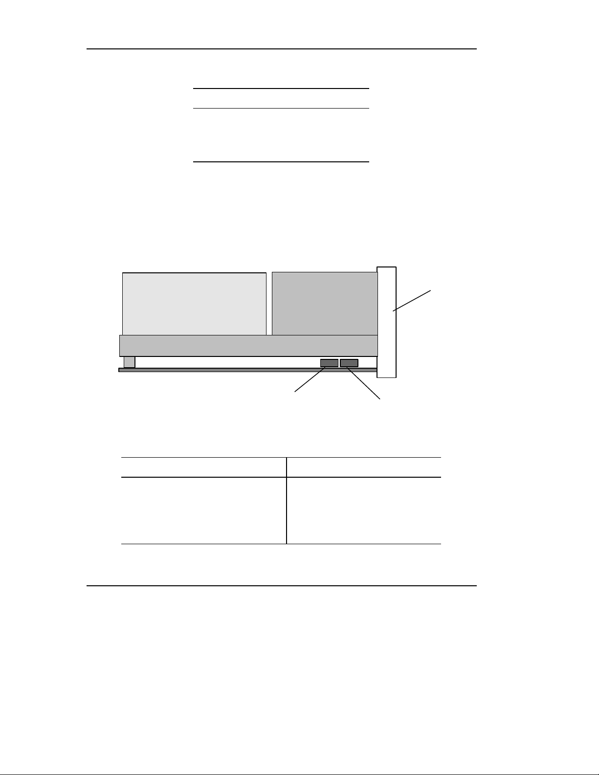
Hardware Implementation
Table 2–4 4-Pin Power Connector Pin Assignments
Pin Number Signal Name
1 +12 VDC
2 Ground (+12 V return)
3 Ground (+5 V return)
4 +5 VDC
Optional Loader Connector (Rackmount)
The loader connector provides signals to be used when the tape drive is part of a
loader/library configuration. Figure 2-5 shows the location of the connector; pin
assignments for the loader connector are listed in Table 2-5.
Front Panel
SCSI ID Jumper Block
Figure 2–5 Loader Connector Block Location (Rackmount Version Shown)
Table 2–5 10-Pin Loader Connector Pin Assignments
Signal Name Pin Number Pin Number Signal Name
Loader_Present L 1 6 Send_to_Loader (-) L
Rec_From_Loader (+) H 2 7 DEL23 L
Rec_From_Loader (-) L 3 8 DEL24 L
DEL27 L 4 9 DEL25 L
Send_to_Loader (+) H 5 10 DEL26 L
2-12 Quantum DLT 7000 Tape Drive
10-Pin Loader Connector
Page 51
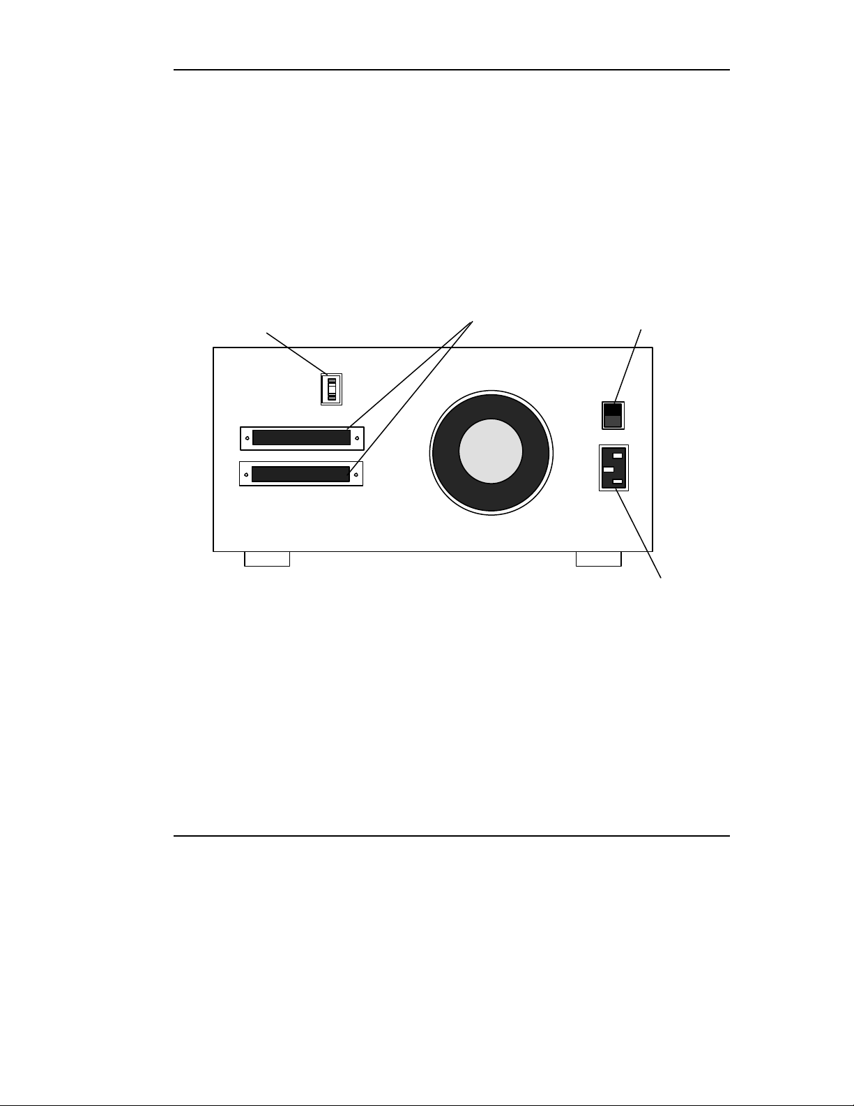
Hardware Implementation
2.3 CONFIGURING AND INSTALLING A TABLETOP DRIVE
This section provides instructions for configuring and installing the tabletop
version of the tape drive.
2.3.1 Configuring the Tabletop Drive
Figure 2-6 shows the location of the controls and connectors for the tabletop
version of the drive. Note that this drive is normally configured to meet customer
specifications before leaving the factory so should not require any internal
configuration changes on-site.
SCSI Connector (2)
SCSI ID Pushbutton
Figure 2–6 Tabletop Back Panel
SCSI ID - The SCSI ID default for the tabletop drive is set to 5; the drive can be
configured for SCSI ID addresses that range from 0 to 15 using the SCSI ID
pushbutton. Press the button above or below the ID number display to set the
desired SCSI ID. The top button increases the ID number; the bottom button
decreases the ID number.
Power Switch
Power Connector
TERMPWR and/or Parity Check - The tabletop version of the drive can be
internally configured to supply TERMPWR or parity checking. Contact your
service representative if you want to change either of these settings on the
tabletop version of the drive.
Quantum DLT 7000 Tape Drive 2-13
Page 52

Hardware Implementation
2.3.2 Installing the Tabletop Drive
Installing the tape drive consists of connecting SCSI bus and power cables.
Figure 2-6 shows the location of the two SCSI bus connectors and power
connector on the back of the tabletop drive.
SCSI Cables
The SCSI bus cable leading from the host adapter can be connected to either of
the connectors. If the tape unit is the last device on the bus, then a terminator
should be installed on the open connector. If the bus continues from the tape
drive to another SCSI device, then install a SCSI bus cable between the open
connector and the next device on the bus.
Carefully align connectors to avoid bending or damaging the connector pins.
1. Make sure the power switch is in the off (0) position.
2. Carefully align and connect one end of the SCSI cable to a SCSI connector
on the back of the drive. Connect the other end of the SCSI cable to the
SCSI connector on your system, or for daisy-chained configurations, to
another SCSI device.
3. Snap the wire cable clamps into place to secure the cables.
4. Be sure to terminate the SCSI bus. If the tabletop drive is the last or only
device on the bus, terminate the bus by connecting the SCSI terminator to
the remaining SCSI connector on the back of the drive. Depending on the
terminator supplied (single-ended terminator = 50 LD Amphenol # 16706,
differential terminator = 50 LD Amphenol #11541), snap the wire cable
clamps into place or tighten the screws to secure the terminator.
If the tabletop drive is not the last or only device on the bus, install a
terminator on the last device on the SCSI bus.
AC Power Cable
An ac power cord is supplied with each tabletop tape unit. Carefully inspect the
power cord and ensure that the cord is the appropriate cord for your country or
region based on the criteria below.
WARNING
Do not attempt to modify or use an external 100 - 115 VAC power
cord for 220 - 240 VAC input power. Modifying the power cord in
any way can cause personal injury and severe equipment damage.
2-14 Quantum DLT 7000 Tape Drive
Page 53

Hardware Implementation
220 / 240 V
The ac power cord used with the tabletop tape unit must meet the following
criteria:
• The power cord should be a minimum of 18/3 AWG, 60°C, Type SJT or SVT.
• UL and CSA Certified cordage rated for use at 250 VAC with a current rating
that is at least 125% of the current rating of the product.
• The ac plug must be terminated in a grounding-type male plug designed for
use in your country or region. It must also have marks showing certification
by an agency acceptable in your country or region.
• The connector at the tabletop unit end of the cord must be an IEC type CEE-
22 female connector.
• The cord must be no longer than 14.5 feet (4.5 meters).
Figure 2-7 shows different ac power cord plug-end configurations for 115 V and
220 / 240 V usage.
115 V
Figure 2–7 AC Power Cord Connector Types
Quantum DLT 7000 Tape Drive 2-15
Page 54
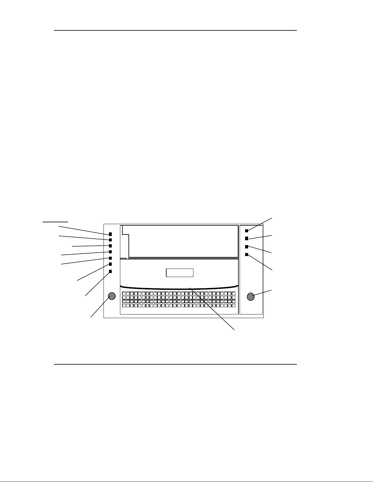
Hardware Implementation
DLT
Density Override LED
Tape In Use LED
20.0
35.0
Note that the power supply of the tabletop unit has an auto-sensing feature; no
adjustment or switch setting changes are required for different ac sources.
Refer to Figure 2-6. Connect one end of the power cord to the power connector on
the back of the drive. Connect the other end of the cord to the ac outlet.
2.4 DRIVE CONTROLS AND LIGHT EMITTING DIODES (LEDS)
This section identifies the front panel controls and LEDs and describes their
functionality. It also explains density selection.
2.4.1 Front Panel Controls and LEDs
This section describes the front panel controls and Light Emitting Diodes (LEDs)
used to operate the tape drive; all controls and LEDs are located on the tape
drive’s front panel. Figure 2-8 shows the locations of the controls and LEDs on
the front panel; Tables 2-6 through 2-8 describe control and LED functionality.
In addition to the controls and LEDs, the tape drive also has an audible beeper
that signals when the drive’s cartridge insert/release handle can be safely used.
Use these controls and LEDs to operate the tape drive and monitor the tape
drive’s activities.
Density LEDs
2.6
6.0
10.0/15.0
Compress LED
Density Select Button
Figure 2-8 DLT 7000 Front Panel
2-16 Quantum DLT 7000 Tape Drive
Write-Protected LED
Use Cleaning Tape LED
Operate Handle LED
Unload Button
Cartridge Insert/Release Handle
Page 55

Hardware Implementation
Table 2–6 LED Functionality
LED LED Color Description
Operate Handle Green On = Insert/Release handle can be operated.
Off = Do not operate Insert/Release handle.
Blinking = Close the Insert/Release handle and wait for Operate
Handle LED to light steadily.
Density -
2.6, 6.0,
10.0/15.0, 20.0
Compress Amber On = Compression mode enabled (compression only valid for
Density Override Amber On = Operator selected a density from the density Select
Write-Protected Orange On = Tape is Write-Protected
Tape In Use Amber Irregular Blinking = Tape is moving; the drive is calibrating,
Amber Refer to Table 2-7 and subsection 2.4.2.
10, 15, or 20 or 35 GB densities only).
Off = Compression mode disabled.
Blinking = Compress mode manually overridden by operator.
Button on the front panel.
Off = Density to be selected by the host (automatic).
Refer to subsection 2.4.2 for Density Select information.
Off = Tape is Write-Enabled
reading, writing, or rewinding the tape.
Regular Blinking = The tape is loading, unloading, or
rewinding.
On = A cartridge is loaded in the tape drive, but the tape is not
moving; the drive is ready for use. This may also mean no
application is communicating with the tape drive’s controller,
or that the application is communicating but is not delivering
any command that impact tape motion.
Off = No tape is loaded.
Quantum DLT 7000 Tape Drive 2-17
Page 56

Hardware Implementation
Table 2–6 LED Functionality (continued)
LED LED Color Description
Use Cleaning Tape Amber On = Tape drive needs cleaning or tape is bad.
Remains on after cleaning tape unloads = Cleaning tape
attempted to clean the drive head, but the tape expired so
cleaning was not done.
After cleaning, LED lights again when (data) tape cartridge is
reloaded = Problem tape cartridge. Try another cartridge. If
problem persists, contact service representative.
Off = Cleaning is complete or cleaning is unnecessary.
Appendix D has more information on cleaning tape usage.
2-18 Quantum DLT 7000 Tape Drive
Page 57

Table 2–7 Density LED Functionality
Hardware Implementation
Density LED
(Amber)
2.6 On = Tape is recorded in 2.6 GB format.
6.0 On = Tape is recorded in 6.0 GB format.
10.0 / 15.0 On = Tape is recorded in 10.0 GB (DLTtape III cartridge) / 15.0 GB (DLTtape
20.0 On = Tape is recorded in 20.0 GB (DLTtape IV cartridge) format (85,633 BPI
35.0 On = Tape is recorded in 35.0 GB format (81,937 BPI density).
Description
Blinking = Tape is being forced by operator to record in this density; 2.6 GB
has been selected for a WRITE from BOT.
Blinking = Tape is being forced by operator to record in this density; 6.0 GB
has been selected for a WRITE from BOT.
IIIxt cartridge) format (62,500 BPI density).
Blinking = Tape is being forced by operator to record in this density, 10.0
GB / 15.0 GB has been selected for a WRITE from BOT.
density).
Blinking = Tape is being forced by operator to record in this density, 35.0 GB
has been selected for a WRITE from BOT.
Blinking = Tape is being forced by operator to record in this density, 35.0 GB
has been selected for a WRITE from BOT.
Note that these LEDs operate only if the correct media is loaded in the drive. For example,
the default density of a DLTtape IV cartridge is 20.0 GB; if you are using a DLTtape IV
cartridge, the density must be set to 20.0 GB. If you set the density to a different setting, the
LEDs do not light and the density function does not work properly.
Quantum DLT 7000 Tape Drive 2-19
Page 58

Hardware Implementation
Table 2-8 Control Functionality
Control Description
Density Select Button Refer to subsection 2.4.2.
Unload Button Use the Unload button to unload the tape cartridge. When you
push the Unload button, the tape drive waits until any active
writing of data to tape is completed, then begins its unload
sequence.
The drive rewinds the tape medium back into the cartridge and
writes the current or updated tape directory to the tape. The tape
must be completely rewound and unloaded into the cartridge
before the cartridge can be removed from the tape drive. A
complete unload operation may take 17 seconds from Beginning
of Tape (BOT).
Note that if the tape drive is in an error state (all LEDs on the rightor left-hand side of the front panel are flashing), pushing the
Unload button causes the tape drive to reset and unload the tape, if
possible. The Operate Handle LED will be lit steady if this is
possible.
Cartridge Insert/Release
Handle
Operate Handle Beeper A beeper sound indicates that the cartridge insert/release handle
Use the Cartridge Insert/Release Handle to load or eject a tape
cartridge only when the tape drive’s Operate Handle LED is lit and
after the beeper sounds its tone. Lift the handle to its fully open
position, or lower it to its fully closed position.
can be safely operated. When the drive emits its single beep tone,
verify that the green Operate Handle LED is lit steadily before
opening the handle.
CAUTION: To prevent damage to the tape drive, never operate the
insert/release handle unless the green Operate Handle LED is lit and
you have heard the beep tone that signals that the tape drive’s
handle can be opened.
2-20 Quantum DLT 7000 Tape Drive
Page 59

2.4.2 Selecting Density
This subsection describes the drive’s density select features.
CAUTION
If a prerecorded tape is reused and a WRITE from the beginning of
tape (BOT) executes (No Append Write), any data already recorded
on the tape will be lost. This includes density changes, since they
occur only when writing from BOT.
NOTES
On all READ and all WRITE APPEND operations, the data density that
already exists on the tape cartridge remains the density.
Default density of a DLTtapeTM III cartridge is 10.0 GB, native. The
only optional selections for DLTtape III cartridges are 2.6 GB, 6.0 GB,
10.0 GB (compression OFF), or 20.0 GB (compression ON).
Hardware Implementation
Default density of a DLTtape IIIxt cartridge is 15.0 GB, native
(compression OFF), or 30.0 GB (compression ON). No other density is
supported.
Default density of a DLTtape IV cartridge is 35.0 GB, native
(compression OFF), or 70.0 GB (compression ON). A density of 20.0
GB native (compression OFF), or 40.0 GB (compression ON) is userselectable. No other density is supported.
When writing from BOT, tape density may be changed by:
• Using the Density Select Button on the front panel of the tape drive. Using
the Density Select Button always overrides density selection via the host.
• Using the operating system to issue a density designation. In this case, the
amber Density Override LED on the tape drive’s front panel turns off,
indicating an automatic or host density selection.
• Native default density for the DLTtape IV is 35.0 GB (70.0 GB,
compressed), assuming the Density Select Button was not used or that host
selection of density via the operating system was not invoked.
Quantum DLT 7000 Tape Drive 2-21
Page 60

Hardware Implementation
Selecting Density on the Tape Drive
To select density on the tape drive:
1. Load the tape cartridge into the tape drive. The amber Tape in Use LED
blinks while the tape loads and calibrates.
2. After calibration is complete, the Tape In Use LED remains steadily lit. The
appropriate tape density LED along the left edge of the drive’s front panel
lights to indicate the tape’s prerecorded density (if any), such as 2.6 GB or
6.0 GB.
3. Use the tape drive’s density Select Button to select the desired density, if
different than that indicated by the lighted tape density LED. Density
selection is inactive until a WRITE from BOT is issued. The controller
retains the selected density until 1) the density selection is changed, or 2)
the tape is unloaded.
For Example:
A user loads a tape cartridge previously recorded at 2.6 GB density. The user then
presses the Density Select button to select 10.0 GB density. The following events
take place:
• The amber 2.6 LED remains lit – the density has not yet changed and the
steadily lit LED reflects the tape’s recorded density.
• The amber 10.0 LED blinks – this signals that a density change is pending.
• The amber Density Override LED lights.
When a WRITE from BOT occurs:
• The amber 2.6 LED turns off
• The amber 10.0/15.0 LED lights steadily
• The amber Density Override LED remains lit
Table 2-9 explains the activity of LEDs during density selection.
2-22 Quantum DLT 7000 Tape Drive
Page 61

Table 2–9 LED Activity During Density Selection
If… Then…
Hardware Implementation
The density Select Button
is not used
The density Select Button
is used and the actual
tape density is the same
as the density selected
via the button
The density Select Button
is used and the actual
tape density differs from
the density selected via
the button
The lighted LEDs show the actual density when the tape is
being read from and written to. The LEDs light steadily;
Density Override LED remains off.
The LED that reflects the actual density and the Density
Override both are lit. For example, if the actual density is
10.0 GB and 10.0 GB is selected via the Select Button, the
LED next to “10.0” lights.
The LED that reflects the actual density lights steadily. The
LED that reflects the SELECTED density blinks. The Density
Override lights steadily.
For example, if the actual tape density is 10.0 GB and the
selected density is 6.0 GB, the 10.0 LED lights steadily, the
6.0 LED blinks, and the Density Override LED lights steadily.
Selecting Density via the Host over the SCSI Bus
1. Use the SCSI MODE SELECT command to indicate the desired density
(Chapter 5).
2. Write data to the tape from BOT.
2.5 POWER ON SELF TEST (POST)
When power is applied to the tape drive, the drive performs a POST. POST
completes in about 15 seconds and the tape drive should respond normally to all
commands; POST is complete after Stage 2 in Table 2-10. However, it might take
longer for the media to become ready.
After a bus reset, the tape drive responds within a bus selection time-out period
(per the ANSI SCSI specification). A reset may have the Tape In Use indicator
blinking because a reset forces the tape to be rewound to BOT.
The following table lists the sequence of events:
Quantum DLT 7000 Tape Drive 2-23
Page 62

Hardware Implementation
Table 2–10 POST/Media Ready Activity
Stage Activity
1 The LEDs along the right-hand side of the front panel light in sequence from
top to bottom. All LEDs remain lit for a few seconds.
2 The LEDs along the left-hand side of the front panel light together for about
three seconds then turns off. POST is complete after this stage.
3 The green Operate Handle, orange Write Protected, and amber Use Cleaning
Tape LEDs turn off. The amber Tape in Use LED blinks while the tape drive
initializes.
4 Following initialization, the tape drive is in one of the states described in Table
2-11. Upon completion, the POST is successful. If the POST is not successful,
refer to Section 2.6 Troubleshooting.
Table 2–11 Tape Drive States Following Initialization
State LED Display and Activity
A tape cartridge is present and
the handle is down.
No tape cartridge present. The Tape in Use LED = Off. The Operate Handle LED = On.
A tape cartridge is present, but
the handle is up (not
recommended).
The tape drive detects an error
condition.
The drive is powered on with
the handle in open position.
The tape drive loads the medium from the cartridge. The
Tape In Use LED stops blinking and remains on. The LED next
to the tape’s actual density is on. When the Density Override
LED blinks, a density may be selected. The tape drive is ready
for use and the media is positioned at BOT.
Insert/Release Handle is unlatched. Tape drive beeper sounds
tone to signal that the handle may be raised and a tape
cartridge inserted.
The Tape In Use LED = Off. The Operate Handle LED flashes.
When the Insert/Release Handle is lowered, the cartridge
loads. If handle will not lower, ensure the tape cartridge is
pushed all the way into the tape drive.
Right- or left-hand LEDs blink repeatedly. Try to unload the
tape and reinitialize the tape drive by pressing the Unload
button or turn the drive power off then back on. The LEDs
stop blinking and the drive attempts to reinitialize. Note that
after pressing the Unload button you may have to wait five
minutes before the Operate Handle LED lights due to the
retry. The LEDs light steadily, then turn off if the test
succeeds.
Operate Handle LED is blinking. Close the Insert/Release
Handle and wait for LED to light steadily.
2-24 Quantum DLT 7000 Tape Drive
Page 63

Hardware Implementation
2.6 TROUBLESHOOTING
Table 2-12 lists troubleshooting tips in the event that your tape drive fails its
power-on self test or if it signals a problem via its front panel LEDs.
If, after attempting the recommended actions listed in Table 2-12, the problem still
exists or recurs, a hardware failure may be the cause. Contact your service
representative.
Table 2–12 Troubleshooting Chart
If… Then… You Should…
System does not
recognize the tape
drive.
System may not be configured
to recognize the SCSI ID.
SCSI ID may not be unique Change the SCSI ID and reconfigure the
SCSI adapter parameters may
not be correct
SCSI signal cable may be loose Ensure SCSI cable is fully seated at each
SCSI terminator may be loose
or not present on the bus
SCSI bus may not be
terminated correctly
SCSI terminator may not be at
end of bus or more than two
terminators may be present.
Configure system to recognize the tape
drive’s ID.
system. The new ID becomes effective at
the next power on or SCSI bus reset.
Check SCSI adapter documentation.
connector end.
Ensure correct, secure termination of bus.
If tape drive is last or only device on bus
(except for adapter), make sure terminator
is installed on tape drive.
If tape drive is not the last or only device
on the bus, check the cable connections
and ensure that the bus is properly
terminated at each end.
Ensure that a terminator is installed at each
end of the bus. One terminator is usually
installed at the host end of the bus.
SCSI bus may be too long.
Too many devices on the bus.
Quantum DLT 7000 Tape Drive 2-25
Limit bus length to ANSI SCSI standard for
the SCSI interface being used.
Limit the number of devices on the bus
(including the SCSI adapter) to match the
limits of the interface being used.
Page 64

Hardware Implementation
Table 2–12 Troubleshooting Chart (Continued)
If… Then… You Should…
System does not
recognize the tape
drive (cont.)
The tape drive does
not power up.
All LEDs on the right
or on the left side of
the tape drive front
panel are blinking.
When loading a tape
cartridge, the LEDs
on the right side of
the tape drive front
panel are blinking.
A device may not have been
turned on and a valid SCSI ID
may not have been
configured prior to the
system powering on and
loading BIOS.
No power is reaching the
tape drive.
A drive fault has occurred. If a tape was loaded, try to unload the tape
The tape drive has detected a
possible drive leader
problem.
Turn drive power on first, and then turn on
power to the system. Do this so that the
drive is properly recognized by the system.
Check the tape drive’s power cable
connection at the rear of the drive.
and reinitialize the drive by pressing the
Unload button, or by turning power to the
drive off then back on. The LEDs stop
blinking as the drive attempts to reinitialize.
The LEDs light steadily again, then
extinguish if the test succeeds. Be sure to
isolate the tape that was loaded in the drive
and perform the Tape Cartridge Inspection
Procedure described in appendix D.2.
CAUTION: If this happens multiple times,
contact your service representative.
Isolate the tape cartridge from all other tape
devices; not doing so may damage another
tape device. Perform the Tape Cartridge
Inspection Procedure described in appendix
D.2 on the tape cartridge. Contact your
service representative.
Nonfatal or fatal
errors occur for
which the cause
cannot be
determined.
SCSI bus termination or the
SCSI bus cable connections
may be incorrect.
The ac power source
grounding may be incorrect
(tabletop version).
Ensure the SCSI bus is terminated and that
all connections are secure.
Use an
ac outlet for the tabletop tape unit on the
same ac line used by the host system.
If, after attempting the recommended actions listed in Table 2-12, the problem still
exists or returns, a hardware failure may be the cause. Contact a service
representative. Also, the web site http://www.dlttape.com includes valuable
information about DLTtape systems.
2-26 Quantum DLT 7000 Tape Drive
Page 65

Chapter 3
SCSI DESCRIPTION
This chapter provides a detailed description of the logical interfaces of the tape drive. The drive is
fully compliant with the ANSI SCSI-2 standard for tape drive devices and implements many optional
features.
3.1 SCSI OVERVIEW
The Small Computer System Interface (SCSI) is a specification for a peripheral
bus and command set that is an ANSI standard. The standard defines an I/O
bus that supports up to 16 devices (wide SCSI).
ANSI defines three primary objectives of SCSI-2:
1. To provide host computers with device-independence within a class of
devices
2. To be backward-compatible with SCSI-1 devices that support bus parity and
that meet conformance level 2 of SCSI-1
3. To move device-dependent intelligence to the SCSI-2 devices
Important features of SCSI-2 implementation include the following:
• Efficient peer-to-peer I/O bus with up to 16 devices
• Asynchronous transfer rates that depend only on device implementation and
cable length
• Logical addressing for all data blocks (rather than physical addressing)
• Multiple initiators and multiple targets
• Distributed arbitration (bus contention logic)
• Command set enhancement
Quantum DLT 7000 Tape System 3-1
Page 66

SCSI Description
3.2 SCSI COMMANDS
ANSI classifies SCSI commands as mandatory, optional, or vendor-specific. The
mandatory and optional commands implemented for the drives are summarized
in Table 3–1 and described fully in Chapter 5, SCSI Commands.
Table 3–1 Implemented ANSI SCSI-2 Commands
Command Code Class Description
ERASE 19h Mandatory Causes all of the tape medium to be
erased, beginning at the current position
on the logical unit.
INQUIRY 12h Mandatory Requests that information be sent to the
initiator. The initiator may also request
additional information about the drive.
LOAD UNLOAD 1Bh Optional Causes tape to move from not ready to
ready. Prior to performing the load
unload, the target ensures that all data,
filemarks, and/or setmarks shall have
transferred to the tape medium.
LOCATE 2Bh Optional Causes the target to position the logical
unit to the specified block address in a
specified partition. When complete, the
logical position is before the specified
position.
LOG SELECT 4Ch Optional Provides a means for the initiator to
manage statistical information
maintained by the drive about the drive.
This standard defines the format of the
log pages but does not define the exact
conditions and events that are logged.
LOG SENSE 4Dh Optional Provides a means for the initiator to
retrieve statistical information
maintained by the drive about the drive.
3-2 Quantum DLT 7000 Tape System
Page 67

SCSI Description
Table 3–1 Implemented ANSI SCSI-2 Command (continued)
Command Code Class Description
MODE SELECT (6) 15h Optional Provides a means for the initiator to
specify device parameters.
MODE SENSE (6)/(10) 1Ah/
5Ah
PREVENT ALLOW
MEDIUM REMOVAL
READ 08h Mandatory Requests the drive to transfer data to the
READ BLOCK LIMITS 05h Mandatory Requests that the logical unit’s block
READ BUFFER 3Ch Optional Used in conjunction with the WRITE
READ POSITION 34 h Optional Reports the current position of the
RECEIVE DIAG
RESULTS
1Eh Optional Requests that the target enable or
1Ch Optional Requests analysis data to be sent to the
Optional Provides a means for a drive to report
parameters to the initiator.
disable the removal of the medium in
the logical unit. Medium cannot be
removed if any initiator has medium
removal prevented.
initiator.
length limits capability be returned.
BUFFER command as a diagnostic
function for testing target memory and
the integrity of the SCSI bus. This
command does not alter the medium.
logical unit and any data blocks in the
buffer.
initiator after completion of a SEND
DIAGNOSTIC Command.
RELEASE UNIT 17h Mandatory Used to release a previously reserved
logical unit.
REQUEST SENSE 03h Mandatory Requests the drive to transfer sense data
to the initiator.
RESERVE UNIT 16h Mandatory Used to reserve a logical unit.
SEND DIAGNOSTIC 1Dh Mandatory Requests the drive to perform diagnostic
operations on itself.
Quantum DLT 7000 Tape System 3-3
Page 68

SCSI Description
Table 3–1 Implemented ANSI SCSI-2 Command (continued)
Command Code Class Description
SPACE 11h Mandatory Provides a selection of positioning
functions (both forward and backward)
that are determined by the code and
count.
TEST UNIT READY 00h Mandatory Provides a means to check if the logical
unit is ready.
VERIFY 2Fh Optional Requests the drive to verify the data
written to the medium.
WRITE 0Ah Mandatory Requests the drive to write the data
transferred from the initiator to the
medium.
WRITE BUFFER 3Bh Optional Used in conjunction with the READ
BUFFER command as a diagnostic for
testing target memory and the integrity
of the SCSI bus.
Used to update drive firmware from the
host via the SCSI bus.
WRITE FILEMARKS 10h Mandatory Requests that the target write the
specified number of filemarks or
setmarks to the current position on the
logical unit.
3.3 SIGNAL STATES
The following paragraphs describe signal values and SCSI ID bits.
3.3.1 Signal Values
All signal values are actively driven true (low voltage). Because the signal
drivers are OR-tied, the bus terminator’s bias circuitry pulls false when it is
released by the drivers at every SCSI device. If any device asserts a signal, (e.g.,
OR-tied signals), the signal is true. Table 3–2 lists the ANSI-specified and
defined signal sources. Any device can assert RST at any time.
3-4 Quantum DLT 7000 Tape System
Page 69

Table 3–2 Signal Sources
Signals
SCSI Description
Bus Phase BSY SEL C/D I/O
MSG REQ
BUS FREE None None None None None None
ARBITRATION All Winner None None S ID S ID
SELECTION I&T Init None Init Init Init
RESELECTION I&T Targ Targ Init Targ Targ
COMMAND Targ None Targ Init Init None
DATA IN Targ None Targ Init Targ Targ
DATA OUT Targ None Targ Init Init Init
STATUS Targ None Targ Init Targ None
MESSAGE IN Targ None Targ Init Targ None
MESSAGE OUT Targ None Targ Init Init None
All: The signal is driven by all SCSI devices that are actively arbitrating.
SCSI ID: Each SCSI device that is actively arbitrating asserts its unique SCSI ID bit. The other
seven (or fifteen) data bits are released. The parity bit DB(P or P1) can be released or
driven true, but is never driven false during this phase.
I&T: The signal is driven by the initiator, drive, or both, as specified in the SELECTION and
RESELECTION phase.
Init: If driven, this signal is driven only by the active initiator.
None: The signal is released; that is, not driven by any SCSI device. The bias circuitry of the
bus terminators pulls the signal to the false state.
Winner: The signal is driven by the winning SCSI device.
Targ: If the signal is driven, it is driven only by the active drive.
ACK ATN DB(7–0)
DB(P)
DB(15-8)
DB(P1)
3.3.2 SCSI ID Bits
SCSI permits a maximum of eight SCSI devices on a SCSI bus (16 devices are
permitted when using wide SCSI). Each SCSI device has a unique SCSI ID
assigned to it. This SCSI ID provides an address for identifying the device on the
bus. On the drive, the SCSI ID is assigned by configuring jumpers or connecting
remote switches to the option connector. Chapter 2, Hardware Implementation
has full instructions for setting the SCSI ID.
Quantum DLT 7000 Tape System 3-5
Page 70

SCSI Description
3.4 SCSI SIGNALS
The following paragraphs define SCSI signals and bus timing values.
3.4.1 SCSI Signal Definitions
Table 3–3 defines the SCSI bus signals.
Table 3–3 SCSI-2 Bus Signal Definitions
Signal Definition
ACK (acknowledge) A signal driven by the initiator as an acknowledgment of
receipt of data from a target or as a signal to a target
indicating when the target should read the data (out) lines.
ATN (attention) A signal driven by an initiator to indicate that it has a message
to send.
BSY (busy) An OR-tied signal that indicates that the bus is in use.
C/D (control/data) A signal driven by a target that indicates whether CONTROL or
DATA information is on the DATA BUS. True (low voltage)
indicates CONTROL.
DB(7–0,P) (data bus) Eight data-bit signals, plus a parity-bit signal that form a DATA
BUS. DB(7) is the most significant bit and has the highest
priority (8 or 16-bit) during ARBITRATION. Bit number,
significance, and priority decrease downward to DB(0). A data
bit is defined as 1 when the signal value is true (low voltage)
and 0 when the signal value is false (high voltage). Data parity
DB(P) is odd. Parity is undefined during ARBITRATION.
DB(15–8,P1) (data bus) Eight data-bit signals, plus one parity-bit signal, that forms an
extension to the DATA BUS. They are used for 16-bit (wide)
interfaces. DB(15) is the most significant bit and has the higher
priority (but below bit DB(0) during ARBITRATION. Bit number,
significance, and priority decrease downward to DB(8). Data
Parity DB (P1) is odd.
3-6 Quantum DLT 7000 Tape System
Page 71

Table 3–3 SCSI-2 Bus Signal Definitions (continued)
Signal Definition
I/O (input/output) A signal driven by a target that controls the direction of data
movement on the DATA BUS with respect to an initiator. True
indicates input to the initiator.
Also used to distinguish between SELECTION and RESELECTION
modes.
MSG (message) A signal driven by a target during the MESSAGE phase.
REQ (request) A signal driven by a target to indicate a request for an
information transfer to or from the initiator. Each byte of data
transferred is accompanied with a REQ/ACK “handshake”. See
also, ACK.
RST (reset) An OR-tied signal that initiates a RESET condition.
SEL (select) An OR-tied signal used by an initiator to select a target or by a
target to reselect an initiator.
3.4.2 Signal Bus Timing
SCSI Description
The ANSI SCSI-2 standard defines the SCSI bus timing values shown in Table
3–4.
Table 3–4 SCSI Bus Timing Values
Timing Description Value Description
Arbitration Delay 2.4 µs Minimum time a SCSI device waits from asserting BSY
for arbitration until the DATA BUS can be examined to
see if arbitration has been won; there is no maximum
time.
Assertion Period 90 ns Minimum time a drive asserts REQ while using
synchronous data transfers; also, the minimum time
that an initiator asserts ACK while using synchronous
data transfers.
Quantum DLT 7000 Tape System 3-7
Page 72

SCSI Description
Table 3–4 SCSI Bus Timing Values (continued)
Timing Description Value Description
Bus Clear Delay 800 ns Maximum time for a SCSI device to stop driving all
bus signals after:
1. BUS FREE is detected. 2.
SEL is received from another SCSI device during
ARBITRATION. 3.
Transition of RST to true.
For condition 1, the maximum time for a SCSI device
to clear the bus is 1200 ns (1.2 µs) from BSY and SEL
first becoming both false.
If a SCSI device requires more than a bus settle delay
to detect BUS FREE, it clears the bus within a bus clear
delay minus the excess time.
Bus Free Delay 800 ns Maximum time a SCSI device waits from its detection
of BUS FREE until its assertion of BSY when going to
ARBITRATION.
Bus Set Delay 1.8 µs Maximum time for a device to assert BSY and its SCSI
ID bit on the DATA BUS after it detects BUS FREE to
enter ARBITRATION.
Bus Settle Delay 400 ns Minimum time to wait for the bus to settle after
changing certain control signals as called out in the
protocol definitions.
Cable Skew Delay 10 ns Maximum difference in propagation time allowed
between any two SCSI bus signals measured between
any two SCSI devices.
Data Release Delay 400 ns Maximum time for an initiator to release the DATA
BUS signals following the transition of the I/O signal
from false to true.
Deskew Delay 45 ns Minimum time required to wait for all signals
(especially data signals) to stabilize at their correct,
final value after changing.
Disconnection Delay 200 µs Minimum time that a drive waits after releasing BSY
before participating in an ARBITRATION when
honoring a DISCONNECT message from the initiator.
3-8 Quantum DLT 7000 Tape System
Page 73

SCSI Description
Table 3–4 SCSI Bus Timing Values (continued)
Timing Description Value Description
Hold Time 45 ns Minimum time added between the assertion of REQ
or ACK and changing the data lines to provide hold
time in the initiator or drive while using standard
(slow) synchronous data transfers.
Negation Period 90 ns Minimum time that a drive negates REQ while using
synchronous data transfers; also, the minimum time
Power-On to
Selection
10 s
than an initiator negates ACK while using
synchronous data transfers.
1
Recommended maximum time from power
application until a drive is able to respond with
appropriate status and sense data to the TEST UNIT
READY, INQUIRY, and REQUEST SENSE commands.
1
Reset to Selection
Time
250
ms
Recommended maximum time after a hard RESET
1
condition until a drive is able to respond with
appropriate status and sense data to the TEST UNIT
READY, INQUIRY, and REQUEST SENSE commands.
Reset Hold Time 25 µs Minimum time for which RST is asserted; there is no
maximum time.
Selection Abort Time 200 µs Maximum time that a drive (or initiator) takes from its
most recent detection of being selected (or
reselected) until asserting a BSY response.
Selection Time-Out
Delay
250
ms
Recommended minimum time a SCSI device should
1
wait for a BSY response during SELECTION or
RESELECTION before starting the time-out procedure.
Transfer Period
2
Minimum time allowed between the leading edges of
successive REQ pulses and of successive ACK pulses
while using standard or fast synchronous data
transfers. The period range is 200 to 500ns minimum,
standard, or 100 to 500ns minimum, fastsynchronous.
1
Recommended Time.
2
Set during an SDTR message.
Quantum DLT 7000 Tape System 3-9
Page 74

SCSI Description
3.5 SCSI BUS PHASES
The SCSI architecture includes eight distinct phases:
BUS FREE phase
ARBITRATION phase
SELECTION phase
RESELECTION phase
COMMAND phase
DATA phases (In/Out)
STATUS phase
MESSAGE phases (In/Out)
The last four phases are called the “information transfer phases”.
The SCSI bus can never be in more than one phase at any given time. In the
following descriptions, signals that are not mentioned are not asserted.
3.5.1 BUS FREE Phase
The BUS FREE phase indicates that there is no current I/O process and that the
SCSI bus is available for a connection.
SCSI devices detect the BUS FREE phase after the SEL and BSY signals are
both false for at least one bus settle delay.
During normal operation, the BUS FREE phase is entered when the drive
releases the BSY signal. However, the BUS FREE phase can be entered following
the release of the SEL signal after a SELECTION or RESELECTION phase timeout. BUS FREE might be entered unexpectedly. If, for example, an internal
hardware or firmware fault makes it unsafe for the tape drive to continue
operation without a full reset (similar to a power-up reset), or if ATN is asserted
or a bus parity error is detected during non-tape data transfers.
3-10 Quantum DLT 7000 Tape System
Page 75

SCSI Description
CAUTION
Any occurrence of a bus parity error (i.e., a single-bit error) should
be considered serious: it implies the possibility of undetected
double-bit error may exist on the bus. This may cause undetected
data corruption. On properly configured SCSI buses, parity errors
are extremely rare. If any are detected they should be addressed by
improving the configuration of the SCSI bus. A well-configured SCSI
bus in a normal environment should be virtually free of bus parity
errors.
Bus parity errors cause the tape drive to retry the operation, go to
the STATUS phase, or go to BUS FREE and prepare Sense Data.
Retrying of parity errors during Data Out Phase when writing is
normally not done, but can be enabled by changing the
EnaParErrRetry parameter in the VU EEROM Mode Page. This feature
is not enabled by default because of possible negative impact on
device performance (the data stream on writes cannot be pipelined
as well).
Initiators normally do not expect the BUS FREE phase to begin because of the
drive’s release of the BSY signal unless it has occurred after the detection of a
reset condition or after a drive has successfully transmitted or received one of
the following messages:
Messages Transmitted from Drive:
• DISCONNECT
• COMMAND COMPLETE
Messages Received by Drive:
• ABORT
• BUS DEVICE RESET
• RELEASE RECOVERY
Quantum DLT 7000 Tape System 3-11
Page 76

SCSI Description
If an initiator detects the release of the BSY signal by the drive at any other
time, the drive is indicating an error condition to the initiator. The drive can
perform this transition to the BUS FREE phase independently of the state of the
ATN signal. The initiator manages this condition as an unsuccessful I/O
process termination. The drive terminates the I/O process by clearing all pending
data and status information for the affected nexus. The drive can optionally
prepare sense data that can be retrieved by a REQUEST SENSE command.
Bus Free Sequence
1. BSY and SEL signals are continuously false for one bus settle delay.
2. SCSI devices release all SCSI bus signals within one bus clear delay.
If a SCSI device requires more than one bus settle delay to detect the BUS FREE
phase, then it releases all SCSI bus signals within one bus clear delay minus the
excess time to detect the BUS FREE phase.
The total time to clear the SCSI bus cannot exceed one bus settle delay plus one
bus clear delay.
3.5.2 ARBITRATION Phase
The ARBITRATION phase allows one SCSI device to gain control of the SCSI
bus so that it can initiate or resume an I/O process.
The SCSI device arbitrates for the SCSI bus by asserting both the BSY signal
and its own SCSI ID after a BUS FREE phase occurs.
Arbitration Sequence
1. The SCSI device waits for the BUS FREE phase to occur.
2. The SCSI device waits a minimum of one bus free delay after detection of the
BUS FREE phase before driving any signal.
3. The SCSI device arbitrates for the SCSI bus by asserting the BSY signal and
its SCSI ID.
4. The SCSI device waits at least an arbitration delay to determine arbitration
results.
3-12 Quantum DLT 7000 Tape System
Page 77

SCSI Description
NOTE
Step 4 requires that every device complete the arbitration phase to
the point of SEL being asserted (for a SELECTION or RESELECTION
phase) to avoid hanging the bus.
• If a higher priority SCSI ID bit is true on the DATA BUS, the SCSI
device loses the arbitration.
• The losing SCSI device releases the BSY signal and its SCSI ID bit
within one bus clear delay after the SEL signal asserted by the
arbitration winner becomes true.
• The losing SCSI device waits for the SEL signal to become true
before releasing the BSY signal and SCSI ID bit when arbitration is
lost.
• The losing SCSI device returns to Step 1.
• If no higher priority SCSI ID bit is true on the DATA BUS, the SCSI
device wins the arbitration and asserts the SEL signal.
• The winning SCSI device waits at least one bus clear delay plus one
bus settle delay after asserting the SEL signal before changing any
signals.
3.5.3 SELECTION Phase
The SELECTION phase allows an initiator to select a drive to initiate a drive
function.
The SCSI device that won the arbitration has both the BSY and SEL signals
asserted and has delayed at least one bus clear delay plus one bus settle delay
before ending the ARBITRATION phase. The SCSI device that won the
arbitration becomes an initiator by not asserting the I/O signal.
During SELECTION, the I/O signal is negated so that this phase can be
distinguished from the RESELECTION phase.
Quantum DLT 7000 Tape System 3-13
Page 78

SCSI Description
3.5.3.1 Selection Sequence
The initiator:
1. Sets the DATA BUS to the OR of its SCSI ID bit and the drive’s SCSI ID
bit.
2. Asserts the ATN signal (signaling that a MESSAGE OUT phase is to follow
the SELECTION phase).
3. Waits at least two deskew delays.
4. Releases the BSY signal.
5. Waits at least one bus settle delay.
6. Looks for a response from the drive.
The drive:
7. Determines that it is selected when the SEL signal and its SCSI ID bit are
true and the BSY and I/O signals are false for at least one bus settle delay.
8. Can examine the DATA BUS to determine the SCSI ID of the selecting
initiator.
9. Asserts the BSY signal within a selection abort time of its most recent
detection of being selected (this is required for correct operation of the
selection time-out procedure).
The drive does not respond to a selection if bad parity is detected. Also, if more
than two SCSI ID bits are on the DATA BUS, the drive does not respond to
selection.
Note that the initiator will release the SEL signal and may change the DATA
BUS no less than two deskew delays after it detects that the BSY signal is true.
The drive waits until the SEL signal is false before asserting the REQ signal to
enter an information transfer phase. Other signals (e.g., MSG, C/D) may also
be asserted.
3.5.3.2 Selection Time-Out
Two optional time-out procedures are specified for clearing the SCSI bus if the
initiator waits a minimum of a selection time-out delay and there has been no
BSY signal response from the drive.
3-14 Quantum DLT 7000 Tape System
Page 79

The initiator asserts the RST signal and follows these steps:
a) Continues asserting the SEL and ATN signals and releases the DATA
BUS.
b) If it has not detected the BSY signal to be true after at least a selection
abort time plus two deskew delays, the drive releases the SEL and ATN
signals, allowing the SCSI bus to go to the BUS FREE phase.
When responding to selection, SCSI devices ensure that the selection was still
valid within a selection abort time of their assertion of the BSY signal. Failure
to comply with the requirement could result in an improper selection.
3.5.4 RESELECTION Phase
RESELECTION is an optional phase that allows a drive to reconnect to an
initiator to continue an operation that was previously started by the initiator
but was suspended by the drive.
The initiator determines that it is reselected when the SEL and I/O signals and
its SCSI ID bit are true, and the BSY signal is false for at least one bus settle
delay.
SCSI Description
3.5.4.1 Reselection Sequence
The drive:
1. Upon completing the ARBITRATION phase, asserts both the BSY and SEL
signals.
2. Delays at least one bus clear delay plus one bus settle delay.
3. Asserts the I/O signal.
4. Sets the DATA BUS to the logical OR of its SCSI ID bit and the initiator’s
SCSI ID bit.
5. Waits at least two deskew delays.
6. Releases the BSY signal.
7. Waits at least one bus settle delay before looking for a response from the
initiator.
The initiator:
8. Determines that it is selected when the following occur for at least one bus
settle delay: SEL, I/O, and the initiator’s SCSI ID bit are true and BSY is
false.
Quantum DLT 7000 Tape System 3-15
Page 80

SCSI Description
9. Examines the DATA BUS to determine the SCSI ID of the reselecting drive.
10. Asserts the BSY signal within a selection abort time of its most recent
detection of being reselected.
The initiator does not respond to a RESELECTION phase if bad parity is
detected or if more than two SCSI ID bits are on the DATA BUS.
The drive:
11. Detects the BSY signal is true.
12. Asserts the BSY signal.
13. Waits at least two deskew delays.
14. Releases the SEL signal.
15. The drive can then change the I/O signal and the DATA BUS.
The initiator:
16. Detects the SEL signal is false.
17. Releases the BSY signal.
The drive:
18. Continues asserting the BSY signal until it relinquishes the SCSI bus.
3.5.4.2 Reselection Time-Out
Two optional time-out procedures are specified for clearing the SCSI bus if the
initiator waits a minimum of a selection time-out delay and there has been no
BSY signal response from the drive.
1. The initiator asserts the RST signal.
2. The initiator follows these steps:
a) Continues asserting the SEL and ATN signals and releases the DATA
BUS.
b) If it has not detected the BSY signal to be true after at least a selection
abort time plus two deskew delays, releases the SEL and ATN signals,
allowing the SCSI bus to go to the BUS FREE phase.
SCSI devices that respond to the RESELECTION phase must ensure that the
reselection is still valid within a selection abort time of asserting the BSY
signal.
3-16 Quantum DLT 7000 Tape System
Page 81

3.5.5 Information Transfer Phases
1. The tape drive supports wide asynchronous and synchronous data transfers.
2. Both differential and single-ended versions of the tape drive are available.
3. Odd parity is generated during all information transfer phases during which the
device writes data to the SCSI bus, and parity is checked during all transfer phases
in which data is read from the bus by the tape drive. Parity checking can be
disabled (Chapter 2).
4. The ANSI SCSI specification refers to mini-libraries as “medium changers.” In this
chapter the term “mini-libraries” is used to describe these devices.
5. The DLT 7000 supports block size of 1 byte to 16 Mbytes.
6. Disconnects from the SCSI bus are done at regular intervals during information
transfer phases to allow other devices to access the bus. These disconnects are
user-configurable via the Disconnect-Reconnect Page of the SCSI MODE SELECT
command.
7. The tape drive does not act as an initiator on the SCSI bus. Therefore, the drive
does not 1) generate unsolicited interrupts to the bus, 2) initiate its own SCSI
commands, and 3) assert bus reset.
SCSI Description
NOTES
8. A mini-library subsystem is assigned two logical unit numbers (LUNs): the tape
drive is always LUN 0, and the mini-library component has a default LUN of 1, but
may be reconfigured to any LUN from 0 to 15 via the SCSI MODE SELECT command.
The COMMAND, DATA, STATUS, and MESSAGE phases are known as the
Information Transfer Phases because they are used to transfer data or control
information.
The C/D, I/O, and MSG signals are used to distinguish between the different
information transfer phases (Table 3−5). The drive asserts these three signals
and so controls all information transfer phase changes. The drive can also cause
a BUS FREE phase by releasing the MSG, C/D, I/O, and BSY signals. The
initiator can request a MESSAGE OUT phase by asserting the ATN signal.
Quantum DLT 7000 Tape System 3-17
Page 82

SCSI Description
The information transfer phases use one or more REQ/ACK handshakes to
control the information transfer. Each REQ/ACK handshake allows the transfer
of one byte of information. During the information transfer phases, the BSY
signal remains true and the SEL signal remains false. Additionally, the drive
continuously envelopes the REQ/ACK handshake(s) with the C/D, I/O, and
MSG signals in such a manner that these control signals are valid for one bus
settle delay before the assertion of the REQ signal of the first handshake and
remain valid after the negation of the ACK signal at the end of the handshake of
the last transfer of the phase.
After the negation of the ACK signal of the last transfer of the phase, the drive
can prepare for a new phase by asserting or negating the C/D, I/O, and MSG
signals. These signals can be changed together or individually. They can be
changed in any order and can be changed more than once (although each line
should change only once). A new phase does not begin until the REQ signal is
asserted for the first byte of the new phase.
A phase ends when the C/D, I/O, or MSG signal changes after the negation of
the ACK signal. The time between the end of a phase and the assertion of the
REQ signal beginning a new phase is undefined. An initiator is allowed to
anticipate a new phase based on the previous phase, the expected new phase,
and early information provided by changes in the C/D, I/O, and MSG signals.
However, the anticipated phase is not valid until the REQ signal is asserted at
the beginning of the next phase.
Information Transfer Direction
True I/O Signal: from drive to initiator
False I/O Signal: from initiator to drive
3-18 Quantum DLT 7000 Tape System
Page 83

Signal
SCSI Description
Table 3–5 Information Transfer Phases
MSG
0 0 0 DATA OUT Initiator to drive.
0 0 1 DATA IN Drive to initiator.
0 1 0 COMMAND Initiator to drive.
0 1 1 STATUS Drive to initiator.
1 1 0 MESSAGE OUT Initiator to drive.
C/D I/O Phase Name Direction of Transfer/ Definition
Allows the drive to request that data be sent from
the initiator to the drive.
Allows the drive to send data to the initiator.
Allows the drive to request a command from the
initiator.
Allows the drive to send status information be sent
from the drive to the initiator.
Allows the drive to request that message(s) be sent
from the initiator to the drive; the drive invokes
this phase in response to the attention condition
created by the initiator.
The drive handshakes byte(s) until the ATN signal
is negated, except when rejecting a message.
See 3.5.5.4 Message Out-Additional Conditions.
1 1 1 MESSAGE IN Drive to initiator.
Allows the drive to send message(s) to the
initiator.
Quantum DLT 7000 Tape System 3-19
Page 84

SCSI Description
3.5.5.1 Asynchronous Data Transfer
Drive to Initiator Transfer Procedure
1. The drive drives the DB (0-15, P, & P1) signals to their desired values.
2. Drive delays at least one deskew delay plus a cable skew delay.
3. Drive asserts the REQ signal.
4. Initiator reads the DB (0-15, P, & P1) signals.
5. Initiator indicates its acceptance of the data by asserting the ACK signal.
6. When ACK is true at the drive, drive can change or release the DB (0-15,
P, & P1) signals.
7. Drive negates the REQ signal.
8. Initiator negates the ACK signal.
9. Drive can continue the transfer by driving the DB (0-15, P, & P1) signals
and asserting the REQ signal (Steps 1 – 3).
Initiator-to-Drive Transfer Procedure
1. Drive asserts the REQ signal.
2. Initiator drives the DB (0-15, P, & P1) signals to their desired values.
3. Initiator delays at least one deskew delay plus a cable skew delay.
4. Initiator asserts the ACK signal.
5. When ACK is true at the drive, drive reads the DB (0-15, P, & P1)
signals.
6. Drive negates the REQ signal.
7. Initiator can change or release the DB (0-15, P, & P1) signals.
8. Initiator negates the ACK signal.
9. Drive can continue the transfer by asserting the REQ signal (Step 1).
3-20 Quantum DLT 7000 Tape System
Page 85

3.5.5.2 Synchronous Data Transfer
Synchronous Data Transfer is optional and is only used in DATA phases and
only if a synchronous data transfer agreement is established. The REQ/ACK
offset specifies the maximum number of REQ pulses that can be sent by the
drive in advance of the number of ACK pulses received from the initiator,
establishing a pacing mechanism. If the number of REQ pulses exceeds the
number of ACK pulses by the REQ/ACK offset, the drive does not assert the
REQ signal until after the leading edge of the next ACK pulse is received. For
successful completion of the data phase, the number of ACK and REQ pulses
must be equal.
The initiator sends one ACK signal pulse for each REQ pulse received. The ACK
signal can be asserted as soon as the leading edge of the corresponding REQ
pulse has been received.
Drive-to-Initiator Transfer Procedure
1. The drive sets the DB (15–0, P, & P1) signals to the desired values. The DB
(0-15, P, & P1) signals are held valid for a minimum of one deskew delay
plus one cable skew delay after REQ is asserted.
SCSI Description
2. Drive delays at least one deskew delay plus a cable skew delay.
3. Drive asserts the REQ signal for a minimum of one assertion period. Drive
can negate the REQ signal and change or release the DB (0-15, P, & P1)
signals.
4. Initiator reads the DB (0-15, P, & P1) signals within one hold time of the
transition of the REQ signal to true.
5. Initiator indicates its acceptance of the data by asserting an ACK pulse.
6. The drive waits at least the greater or these periods before again asserting
REQ:
a) A transfer period from the last transition of the REQ signal to true, or
b) A negation period from the last transition of the REQ signal to false.
7. The initiator waits at least the greater of these periods before reasserting
ACK:
c) A transfer period from the last transition of the ACK signal to true, or
d) A negation period from the last transition of the ACK signal to false.
Quantum DLT 7000 Tape System 3-21
Page 86

SCSI Description
Initiator-to-Drive Transfer Procedure
Initiator transfers one byte for each REQ pulse received.
1. Drive asserts the REQ signal.
2. After receiving the leading edge of the REQ signal, initiator drives the DB
(0-15, P, & P1) signals to their desired values. The DB (0-15, P, & P1)
signals are held valid for at least one deskew delay plus one cable skew delay
plus one hold time delay after the assertion of the ACK signal.
3. Initiator delays at least one deskew delay plus a cable skew delay.
4. Initiator asserts the ACK signal for a minimum of one assertion period.
5. Initiator can negate the ACK signal and change or release the DB (0-15, P,
& P1) signals.
6. Drive reads the DB (0-15, P, & P1) signals within one hold time of the
transition of the ACK signal to true.
7. The drive waits at least the greater of these periods before again asserting
the REQ signal:
a) A transfer period from the last transition of the REQ signal to true, or
b) A negation period from the last transition of the REQ signal to false.
8. The initiator waits at least the greater of the following periods before again
asserting the ACK signal:
a) A transfer period from the last transition of the ACK signal to true, or
b) A negation period from the last transition of the ACK signal to false.
3.5.5.3 Signal Restrictions Between Phases
When the SCSI bus is between two information transfer phases, the following
restrictions apply to the SCSI bus signals:
• The BSY, SEL, REQ, and ACK signals do not change.
• The C/D, I/O, MSG, and DATA BUS signals can change.
• When changing the DATA BUS direction from out (initiator-driving) to in
(drive-driving), the drive delays driving the DATA BUS by at least a data
release delay plus one bus settle delay after asserting the I/O signal. The
initiator releases the DATA BUS no later than a data release delay after the
transition of the I/O signal to true.
3-22 Quantum DLT 7000 Tape System
Page 87

SCSI Description
• When switching the DATA BUS from in to out, the drive releases the DATA
BUS no later than a deskew delay after negating the I/O signal.
• The ATN and RST signals can change as defined under the descriptions for
the attention condition (Section 3.6.1) and reset condition (Section 3.6.2).
3.5.5.4 STATUS Phase
The tape drive enters the status phase just once per command unless a retry is
requested by the initiator. The only exception is during error cases when the
device goes immediately to bus free, as defined in the ANSI SCSI-2 specification.
Status bytes the tape drive can return are listed in the following table:
Table 3–6 Status Bytes
Status Bytes Returned from Tape Drive Definition
GOOD (00h) This status indicates that the drive successfully completed
the command.
CHECK CONDITION (02h) A contingent allegiance condition occurred. The REQUEST
SENSE command should be sent following this status to
determine the nature of the event.
BUSY (08h) Target is busy. This status is returned whenever the device
is unable to accept a command from an otherwise
acceptable initiator. The initiator should reissue the
command at a later time.
INTERMEDIATE GOOD (10h) This status is returned instead of GOOD for commands
issued with the LINK bit set = 1. Following the return of
this status, the drive proceeds to the COMMAND phase for
the transfer of the next linked command.
RESERVATION CONFLICT (18h) This status is returned by the drive whenever a SCSI device
attempts to access the drive when it has been reserved for
another initiator with a RESERVE UNIT command.
COMMAND TERMINATED (22h) This status is returned for a command that was terminated
via a TERMINATE I/O PROCESS message. This status also
indicates that a contingent allegiance condition has
occurred.
Quantum DLT 7000 Tape System 3-23
Page 88

SCSI Description
In contrast to the BUSY status condition, the DRIVE NOT READY
Sense Key is returned as part of the Sense data following a REQUEST
SENSE command and indicates that a media access command has
been issued but that the media is not ready to be accessed. For
example, the tape cartridge is not installed, the tape medium has
been unloaded, the tape drive is currently initializing the tape
medium to prepare it for access, etc.).
In the DRIVE NOT READY state, the initiator cannot perform any
operation that would cause tape motion (READ, WRITE, VERIFY, for
example). These commands return a CHECK CONDITION status with a
DRIVE NOT READY sense key. The initiator may execute commands
that do not require tape motion or access to the tape medium, and
a GOOD status may be the result.
3.6 SCSI BUS CONDITIONS
The SCSI bus has two asynchronous conditions: Attention and Reset.
NOTES
3.6.1 Attention Condition
The attention condition informs a drive that an initiator has a message ready.
The drive gets the message by performing a MESSAGE OUT phase. The
attention condition requires the following timing:
• The initiator creates the attention condition by asserting ATN at any time
except during the ARBITRATION or BUS FREE phases.
• The initiator negates the ATN signal at least two deskew delays before
asserting the ACK signal while transferring the last byte of the message.
• If the drive detects that the initiator failed to meet this requirement, then
the drive goes to BUS FREE.
• Before transition to a new bus phase, the initiator asserts the ATN signal,
then waits at least two deskew delays before negating the ACK signal for
the last byte transferred in the current bus phase. Asserting the ATN signal
later cannot be honored until a later bus phase and then cannot result in
the expected action.
The drive responds with MESSAGE OUT as described in the following table:
3-24 Quantum DLT 7000 Tape System
Page 89

SCSI Description
Table 3–7 Drive MESSAGE OUT Phase Response
ATN Signal True in Phase... The Drive Enters MESSAGE OUT…
COMMAND After transferring part or all of the command descriptor block
bytes.
DATA At the drive’s earliest convenience (often on a logical block
boundary). The initiator continues REQ/ACK handshakes until it
detects the phase change.
STATUS After the status byte has been acknowledged by the initiator.
MESSAGE IN Before it sends another message. This permits a MESSAGE
PARITY ERROR message from the initiator to be associated with
the appropriate message.
SELECTION
RESELECTION
1
Before the initiator releases BSY, provided the initiator asserted ATN
2
The initiator should only assert the ATN signal during a RESELECTION phase to transmit a BUS
DEVICE RESET or DISCONNECT message.
1
2
Immediately after that SELECTION phase.
After the drive has sent its IDENTIFY message for that
RESELECTION phase.
The initiator keeps the ATN signal asserted if more than one byte is to be
transferred. The initiator can negate the ATN signal at any time, except it does
not negate the ATN signal while the ACK signal is asserted during a MESSAGE
OUT phase. Normally, the initiator negates the ATN signal while the REQ
signal is true and the ACK signal is false during the last REQ/ACK handshake
of the MESSAGE OUT phase.
3.6.2 Reset Condition
The tape drive responds to power-on and/or bus reset conditions as described:
• All tape drive SCSI lines assert high impedance when the tape drive is
powered off.
• The drive does not generate any spurious signals on the SCSI bus when the
drive is powered on.
• Within five (5) seconds of power-on, and within 250 milliseconds (typically
under 4 milliseconds) after a bus reset, the tape drive responds to SCSI bus
selections and returns the appropriate normal responses. Tape motion
commands are returned with Check Condition status, Sense Key of Not
Ready, until the medium has been made ready.
Quantum DLT 7000 Tape System 3-25
Page 90

SCSI Description
• The tape medium is rewound to Beginning of Partition (BOP, i.e.,
Beginning of Tape [BOT]).
Note that the tape drive does not implement the hard reset alternative for bus
RESET processing.
The tape drive recognizes multiple bus resets in succession as well as bus resets
of arbitrarily long duration (powering on conditions). It recovers within the time
limits specified above following the last bus reset.
3.6.3 Queued Unit Attentions
Queued Unit Attentions are implemented on the tape drive and are maintained
separately for each valid LUN for each initiator. Unit Attentions are created as a
result of the following circumstances:
• Power on
• Bus reset
• Bus device reset message
• When the media may have changed asynchronously
• When another initiator has changed the mode parameters
• When a firmware (microcode) update has completed
Two (2) queued Unit Attentions are not unusual. For example, if a drive is
powered up and a cartridge is loaded, “power up” and “not ready to ready
transition” Unit Attention messages are created. Due to a limited number of
Unit Attention buffers, if an initiator does not clear Unit Attentions queued for
it, the tape drive at some point stops generating new Unit Attention messages
for the Initiator-Logical Unit (I-L) combination (existing messages remain
queued).
A LOAD command does not generate a Unit Attention message for the initiator
that issued the command, since the transition to ready is synchronous.
3-26 Quantum DLT 7000 Tape System
Page 91

Chapter 4
MESSAGES
The SCSI message system allows communication between an initiator and the drive for interface
management and command qualification. Messages can be originated by either the initiator or the
drive. This section contains a detailed description of the messages supported by the disk drives.
4.1 MESSAGE FORMAT
A message can be one or more bytes in length. One or more messages can be
sent during a single MESSAGE phase, but a message cannot be split over
MESSAGE phases. The initiator is required to end the MESSAGE OUT phase
(by negating ATN) when it sends certain messages that are identified in
Table 4–2.
When a connection to the drive is established (i.e., the drive is selected with
ATN asserted), the first message byte passed by the initiator must be either an
IDENTIFY, ABORT, or BUS DEVICE RESET message. If not, the drive discards
the message, saves no status information, and goes to the BUS FREE phase.
If an initiator supplies an unsupported message (for example, COMMAND
COMPLETE or a reserved or undefined message code), the drive returns a
MESSAGE REJECT message and continues where it left off (possibly returning
to MESSAGE OUT if ATN is raised).
The first byte of the message, as defined in Table 4–1, determines the format of
the message.
Quantum DLT 7000 Tape System 4-1
Page 92

Messages
Table 4–1 Message Format
Message Code Message
00h One-byte message (COMMAND COMPLETE)
01h Extended message
02h – 1Fh One-byte message
20h – 2Fh Two-byte message
40h – 7Fh Reserved
80h – FFh One-byte message (IDENTIFY)
The DLT 7000 tape drive supports the messages listed in Table 4–2. The
message code and the direction of the message flow is also included in the table
(In = target to initiator, Out = initiator to target).
4-2 Quantum DLT 7000 Tape System
Page 93

Table 4–2 Supported Messages
Message Message Code Direction
ABORT 06h Out
BUS DEVICE RESET 0Ch Out
COMMAND COMPLETE 00h In
DISCONNECT 04h In Out
Messages
EXTENDED MESSAGE (SDTR and wide Data
Transfer Request)
IDENTIFY 80h – FFh In Out
IGNORE WIDE RESIDUE 23h In
INITIATOR DETECTED ERROR 05h Out
LINKED COMMAND COMPLETE 0Ah In
LINKED COMMAND COMPLETE (with flag) 0Bh In
MESSAGE PARITY ERROR 09h Out
MESSAGE REJECT 07h In
NO OPERATION 08h Out
RESTORE POINTERS 03h In
SAVE DATA POINTER 02h In
WIDE DATA TRANSFER REQUEST * 03h In Out
*
Extended messages (Figure 4–1).
*
01h In Out
Two-byte messages consist of two consecutive bytes. The value of the first byte,
as defined in Table 4–1, determines which message is to be transmitted. The
second byte is a parameter byte that is used as defined in the message
description.
A value of 1 in the first byte indicates the beginning of a multiple-byte extended
message. The minimum number of bytes sent for an extended message is three.
The extended message format is shown in Figure 4–1 and the data fields are
described in Table 4–3.
Quantum DLT 7000 Tape System 4-3
Page 94

Messages
Bit
Byte
0 Extended Message (01h)
1 Extended Message Length
2 Extended Message Code
3 to n-1 Extended Message Arguments
7 6 5 4 3 2 1 0
Figure 4–1 Extended Message - Data Format
Table 4–3 Extended Message - Field Description
Field Description
Extended Message Length This field specifies the length, in bytes, of the Extended Message
Code plus the Extended Message Arguments that follow. Therefore,
the total length of the message is equal to the Extended Message
Length plus 2.
A value of 0 for the Extended Message Length indicates that 256
bytes follow.
Extended Message Code The drive supports three Extended Messages. They are: 00h
MODIFY DATA POINTER 01h
SYNCHRONOUS DATA TRANSFER REQUEST 03h
WIDE DATA TRANSFER REQUEST
4-4 Quantum DLT 7000 Tape System
Page 95

4.2 SUPPORTED SCSI MESSAGES
Following are descriptions of each of the messages supported by the drive.
4.2.1 ABORT Message (06h)
This message is sent from the initiator to the target to clear the current I/O
process on the selected unit. Buffered (cached) write operations are completed if
possible. The target goes directly to the BUS FREE phase after successful receipt
of this message. Current settings of MODE SELECT parameters and
reservations are not affected. Commands, data, and status for other initiators
are not affected.
This message can be sent to a logical unit that is not currently performing an
operation for the initiator. If no unit has been selected, the target goes to BUS
FREE phase and no commands, data, or status on the target are affected.
4.2.2 BUS DEVICE RESET Message (0Ch)
The BUS DEVICE RESET message is sent from an initiator to direct the drive to
clear all I/O processes on the drive. The message causes the drive to:
Messages
1. Flush the contents of cache to tape and go to the BUS FREE phase.
2. Execute a hard reset, leaving it as if a Bus Reset had occurred.
The drive creates a Unit Attention condition for all initiators after accepting and
processing a Bus Device Reset message. The additional sense code is set to
POWER ON, RESET, or BUS DEVICE RESET OCCURRED.
4.2.3 COMMAND COMPLETE Message (00h)
The COMMAND COMPLETE message is sent by the drive to an initiator to
indicate that an I/O process has completed and that valid status has been sent
to the initiator. After successfully sending this message, the drive goes to the
BUS FREE phase by releasing the BSY signal. The drive considers the message
transmission successful when it detects the negation of ACK for the
COMMAND COMPLETE message with the ATN signal false. If a COMMAND
COMPLETE message is received by the tape drive, it is handled as an illegal
message: the drive returns MESSAGE REJECT and enters its STATUS phase,
reporting CHECK CONDITION with the sense key set to COMMAND
ABORTED.
Quantum DLT 7000 Tape System 4-5
Page 96

Messages
4.2.4 DISCONNECT Message (04h)
The DISCONNECT message is sent from the drive to inform the initiator that
the present connection is going to be broken (the drive plans to disconnect by
releasing the BSY signal) and a later reconnect will be required to complete the
current I/O process. The message does not cause the initiator to save the data
pointer. After sending the message, the drive goes to the BUS FREE phase by
releasing the BSY signal.
The DISCONNECT message can also be sent by the initiator to tell the drive to
suspend the current phase and disconnect from the bus. The drive’s response to
and its handling of a DISCONNECT message are based on when, in the I/O
process, the initiator introduces the DISCONNECT message. Table 4–4
summarizes the drive’s response.
Table 4–4 Drive Response to DISCONNECT Message
BUS Phase Drive Response
SELECTION The drive discards the DISCONNECT message and goes to BUS FREE.
COMMAND The drive discards the DISCONNECT message and goes to BUS FREE. The
ATTENTION request is ignored while the Command Descriptor Block is
fetched. The drive does not switch to MESSAGE OUT until the current
DMA completes.
DATA The ATTENTION request is ignored while the current data transfer
completes; that is, the drive does not switch to MESSAGE OUT until
after the current DMA completes. The drive returns a MESSAGE REJECT
message and responds with CHECK CONDITION status, indicating the
command aborted because of an invalid message.
STATUS The drive sends a MESSAGE REJECT message, then sends COMMAND
COMPLETE.
MESSAGE IN The drive sends a MESSAGE REJECT message and switches to the BUS
FREE phase.
4-6 Quantum DLT 7000 Tape System
Page 97

4.2.5 IDENTIFY Message (80h - FFh)
The IDENTIFY message is sent by either the initiator or the drive to establish or
re-establish the physical connection path between an initiator and target for a
particular logical unit under the conditions listed below. Figure 4–2 shows the
format of the IDENTIFY message and Table 4–5 describes the data field
contents.
Messages
Bit
Byte
7 6 5 4 3 2 1 0
Identify DiscPriv
LUNTAR
Reserved LUNTRAN
Figure 4–2 IDENTIFY Message - Data Format
Table 4–5 IDENTIFY Message - Field Description
Field Description
Identify The Identify bit must be set to 1. This identifies the message as an IDENTIFY
message.
DiscPriv Disconnect Privilege. The DiscPriv can be 0, provided that no other I/O process
is currently active in the drive. If not set to 1 and other I/O processes are
currently active in the drive, the drive returns BUSY status.
LUNTAR The Logical Unit/Target Routine (LUNTAR) field must be set to zero. The drive
supports a single Logical Unit Number (LUN 0). A LUNTAR bit of one causes
the drive to send a MESSAGE REJECT message and switch to the BUS FREE
phase.
Reserved The Reserved bits must be zero. If a Reserved bit is non-zero, the drive returns
a MESSAGE REJECT message and switches to the BUS FREE phase.
LUNTRN Logical Unit Number.
Quantum DLT 7000 Tape System 4-7
Page 98

Messages
4.2.6 IGNORE WIDE RESIDUE Message (23h)
The IGNORE WIDE RESIDUE message is sent by the target to the initiator to
indicate that the number of valid bytes sent during the last REQ/ACK
handshake and REQB/ACKB handshake of a DATA IN phase is less than the
negotiated transfer width. The Ignore field indicates the number of invalid data
bytes transferred. This message is sent immediately following that DATA IN
phase and prior to any other messages. Figure 4-3 illustrates the data format of
an IGNORE WIDE RESIDUE message. Table 4-6 describes the Ignore field bit
definitions.
Bit
Byte
0
1
7 6 5 4 3 2 1 0
Message Code (23h)
Ignore (01h)
Figure 4–3 IGNORE WIDE RESIDUE Message - Data Format
Table 4–6 IGNORE WIDE RESIDUE Message - Field Definition
Ignore Invalid Data Bits (16-bit Transfers)
00h Reserved
01h DB(15-8)
02h - FFh Reserved
4-8 Quantum DLT 7000 Tape System
Page 99

4.2.7 INITIATOR DETECTED ERROR Message (05h)
The INITIATOR DETECTED ERROR message is sent from an initiator to
inform the drive that an error has occurred that does not preclude the drive from
retrying the operation (a bus parity error, for example). The source of the error
may either be related to previous activities on the SCSI bus or may be only driverelated. When received, the tape drive attempts to re-transfer the last command,
data, or status bytes by using the RESTORE POINTER message mechanism.
The drive’s response to and its handling of an INITIATOR DETECTED ERROR
message are based on when, in the I/O process, the initiator introduces the
message. Table 4–7 summarizes the drive’s response.
Table 4–7 Drive Response to INITIATOR DETECTED ERROR Message
BUS Phase Drive Response
SELECTION The drive discards the INITIATOR DETECTED ERROR message and then
goes to the BUS FREE phase.
COMMAND The drive discards any Command Descriptor Block bytes fetched from
the initiator, sets the Sense Key to ABORTED COMMAND, sets the
Additional Sense Code to INITIATOR DETECTED ERROR MESSAGE
RECEIVED. It sends the CHECK CONDITION status and the COMMAND
COMPLETE message and then goes to the BUS FREE phase.
Messages
DATA The drive discards the INITIATOR DETECTED ERROR message and sets the
Sense Key to ABORTED COMMAND, sets the Additional Sense Code to
INITIATOR DETECTED ERROR MESSAGE RECEIVED. It sends the CHECK
CONDITION status and the COMMAND COMPLETE message and then
goes to the BUS FREE phase.
STATUS The drive sends a RESTORE POINTERS message, returns to the STATUS
phase, resends the STATUS command, and continues the I/O process.
MESSAGE IN The drive discards the INITIATOR DETECTED ERROR message and sets the
Sense Key to ABORTED COMMAND, sets the Additional Sense Code to
INITIATOR DETECTED ERROR MESSAGE RECEIVED. It sends the CHECK
CONDITION status and the COMMAND COMPLETE message and then
goes to the BUS FREE phase.
Quantum DLT 7000 Tape System 4-9
Page 100

Messages
4.2.8 LINKED COMMAND COMPLETE Message (0Ah)
This message is sent from a target to an initiator to indicate that the execution
of a linked command (with the FLAG bit set to zero) is complete and that
status has been sent. The initiator then sets the pointers to the initial state for
the next command.
If received by a target, this message is handled as an illegal message; the drive
enters the MESSAGE IN phase and returns MESSAGE REJECT.
4.2.9 LINKED COMMAND COMPLETE, with Flag Message (0Ah)
This message is sent from a target to an initiator to indicate that the execution
of a linked command (with the FLAG bit set to one) is complete and that status
has been sent.
4.2.10 MESSAGE PARITY ERROR Message (09h)
This message is sent from the initiator to tell the drive that the last message
byte the drive passed on to the initiator contained a parity error.
To indicate that it intends to send the message, the initiator sets the ATN
signal before it releases ACK for the REQ/ACK handshake of the message that
has the parity error. This provides an interlock so that the target can determine
which message has the parity error. If the target receives this message under any
other condition, it proceeds directly to the BUS FREE state by releasing the BSY
signal, signifying a catastrophic error.
The target’s response to this message is to switch to the MESSAGE IN phase
and re-send from the beginning all the bytes of the message that precipitated the
MESSAGE PARITY ERROR message.
4.2.11 MESSAGE REJECT Message (07h)
This message is sent from the initiator or target to indicate that the last
message received was inappropriate or has not been implemented.
To indicate its intention to send this message, the initiator asserts the ATN
signal before it releases ACK for the REQ/ACK handshake of the message that
is to be rejected. MESSAGE REJECT is issued in response to any message the
drive considers to be illegal or not supported. When sending to the initiator, the
tape drive does so before requesting any additional message bytes.
4-10 Quantum DLT 7000 Tape System
 Loading...