

Page 1
Quantum Cascade Laser
Starter Kit
Instructions Manual (Web version)
CAUTION
Before using the Quantum Cascade
Laser Starter Kit, read this
documentation and take special
note of all safety instructions
Page 2

Contents
1 Identification 4
1.1 Document . . . . . . . . . . . . . . . . . . . . . . . . . . . . . . . . . . . . . . . . . . . . . 4
1.2 Limited waranty . . . . . . . . . . . . . . . . . . . . . . . . . . . . . . . . . . . . . . . . . 4
2 General 5
2.1 Chapter overview . . . . . . . . . . . . . . . . . . . . . . . . . . . . . . . . . . . . . . . . . 5
2.2 Generalities . . . . . . . . . . . . . . . . . . . . . . . . . . . . . . . . . . . . . . . . . . . . 5
2.3 Compliance . . . . . . . . . . . . . . . . . . . . . . . . . . . . . . . . . . . . . . . . . . . . 5
2.3.1 Laser compliance . . . . . . . . . . . . . . . . . . . . . . . . . . . . . . . . . . . . . 5
2.4 Glossary . . . . . . . . . . . . . . . . . . . . . . . . . . . . . . . . . . . . . . . . . . . . . . 6
2.4.1 Persons . . . . . . . . . . . . . . . . . . . . . . . . . . . . . . . . . . . . . . . . . . 6
2.4.2 Product . . . . . . . . . . . . . . . . . . . . . . . . . . . . . . . . . . . . . . . . . . 6
2.5 Typographic conventions . . . . . . . . . . . . . . . . . . . . . . . . . . . . . . . . . . . . . 7
3 Safety Instructions 10
3.1 Chapter overview . . . . . . . . . . . . . . . . . . . . . . . . . . . . . . . . . . . . . . . . . 10
3.2 Introduction . . . . . . . . . . . . . . . . . . . . . . . . . . . . . . . . . . . . . . . . . . . . 10
3.2.1 Principle . . . . . . . . . . . . . . . . . . . . . . . . . . . . . . . . . . . . . . . . . 10
3.2.2 Importance of safety instructions . . . . . . . . . . . . . . . . . . . . . . . . . . . . 10
3.2.3 Non-compliance with the safety regulations . . . . . . . . . . . . . . . . . . . . . . 10
3.3 General safety instructions . . . . . . . . . . . . . . . . . . . . . . . . . . . . . . . . . . . . 11
3.4 Environmental conditions . . . . . . . . . . . . . . . . . . . . . . . . . . . . . . . . . . . . 11
3.5 Compliance and information . . . . . . . . . . . . . . . . . . . . . . . . . . . . . . . . . . . 11
4 Description 12
4.1 Chapter overview . . . . . . . . . . . . . . . . . . . . . . . . . . . . . . . . . . . . . . . . . 12
4.2 System Composition . . . . . . . . . . . . . . . . . . . . . . . . . . . . . . . . . . . . . . . 12
4.3 DFB and FP Quantum Cascade Lasers . . . . . . . . . . . . . . . . . . . . . . . . . . . . . 13
4.3.1 Description . . . . . . . . . . . . . . . . . . . . . . . . . . . . . . . . . . . . . . . . 13
4.3.2 Geometry of QC lasers . . . . . . . . . . . . . . . . . . . . . . . . . . . . . . . . . . 13
4.3.3 Specifications . . . . . . . . . . . . . . . . . . . . . . . . . . . . . . . . . . . . . . . 14
4.3.4 Electrical model . . . . . . . . . . . . . . . . . . . . . . . . . . . . . . . . . . . . . 15
4.4 Laboratory Laser Housing(LLH100) . . . . . . . . . . . . . . . . . . . . . . . . . . . . . . 16
4.4.1 Description . . . . . . . . . . . . . . . . . . . . . . . . . . . . . . . . . . . . . . . . 16
4.4.2 Specifications . . . . . . . . . . . . . . . . . . . . . . . . . . . . . . . . . . . . . . . 17
4.4.3 Thermo-Electric Cooler (TEC) and PT100 connections . . . . . . . . . . . . . . . 18
4.4.4 Measurement connection . . . . . . . . . . . . . . . . . . . . . . . . . . . . . . . . . 19
4.5 QCL pulser switching unit(LDD100) . . . . . . . . . . . . . . . . . . . . . . . . . . . . . . 20
4.5.1 Description . . . . . . . . . . . . . . . . . . . . . . . . . . . . . . . . . . . . . . . . 20
4.5.2 Specifications . . . . . . . . . . . . . . . . . . . . . . . . . . . . . . . . . . . . . . . 20
4.6 QCL pulse switching measuring unit . . . . . . . . . . . . . . . . . . . . . . . . . . . . . . 21
4.6.1 Generalities . . . . . . . . . . . . . . . . . . . . . . . . . . . . . . . . . . . . . . . . 21
4.6.2 Measured voltages . . . . . . . . . . . . . . . . . . . . . . . . . . . . . . . . . . . . 21
4.6.3 Timing data . . . . . . . . . . . . . . . . . . . . . . . . . . . . . . . . . . . . . . . 21
4.6.4 Laser peak current . . . . . . . . . . . . . . . . . . . . . . . . . . . . . . . . . . . . 22
1
Page 3

4.6.5 Laser peak voltage . . . . . . . . . . . . . . . . . . . . . . . . . . . . . . . . . . . . 23
4.6.6 Average dissipation . . . . . . . . . . . . . . . . . . . . . . . . . . . . . . . . . . . . 23
4.6.7 Accuracy considerations . . . . . . . . . . . . . . . . . . . . . . . . . . . . . . . . . 23
4.7 QCL pulser timing unit (TPG128) . . . . . . . . . . . . . . . . . . . . . . . . . . . . . . . 24
4.7.1 Description . . . . . . . . . . . . . . . . . . . . . . . . . . . . . . . . . . . . . . . . 24
4.7.2 Specifications . . . . . . . . . . . . . . . . . . . . . . . . . . . . . . . . . . . . . . . 24
4.8 QCL temperature controller(TCU151) . . . . . . . . . . . . . . . . . . . . . . . . . . . . . 25
4.8.1 Description . . . . . . . . . . . . . . . . . . . . . . . . . . . . . . . . . . . . . . . . 25
4.8.2 Specifications . . . . . . . . . . . . . . . . . . . . . . . . . . . . . . . . . . . . . . . 25
4.8.3 Peltier and PT100 connections . . . . . . . . . . . . . . . . . . . . . . . . . . . . . 25
5 Installation 26
5.1 Chapter overview . . . . . . . . . . . . . . . . . . . . . . . . . . . . . . . . . . . . . . . . . 26
5.2 General . . . . . . . . . . . . . . . . . . . . . . . . . . . . . . . . . . . . . . . . . . . . . . 26
5.3 Packing list . . . . . . . . . . . . . . . . . . . . . . . . . . . . . . . . . . . . . . . . . . . . 26
5.3.1 Standard items . . . . . . . . . . . . . . . . . . . . . . . . . . . . . . . . . . . . . . 26
5.4 Setting the appropriate AC voltage on TCU151 . . . . . . . . . . . . . . . . . . . . . . . . 27
5.4.1 Procedure . . . . . . . . . . . . . . . . . . . . . . . . . . . . . . . . . . . . . . . . . 27
5.5 Installing the starter Kit . . . . . . . . . . . . . . . . . . . . . . . . . . . . . . . . . . . . . 28
5.5.1 Before beginning . . . . . . . . . . . . . . . . . . . . . . . . . . . . . . . . . . . . . 28
5.5.2 Procedure . . . . . . . . . . . . . . . . . . . . . . . . . . . . . . . . . . . . . . . . . 28
2
6 Use 30
6.1 Chapter overview . . . . . . . . . . . . . . . . . . . . . . . . . . . . . . . . . . . . . . . . . 30
6.2 QCL pulse timing unit command description . . . . . . . . . . . . . . . . . . . . . . . . . 30
6.3 TCU151 command description . . . . . . . . . . . . . . . . . . . . . . . . . . . . . . . . . 31
6.4 Laser utilisation . . . . . . . . . . . . . . . . . . . . . . . . . . . . . . . . . . . . . . . . . . 32
6.4.1 Overview . . . . . . . . . . . . . . . . . . . . . . . . . . . . . . . . . . . . . . . . . 32
6.4.2 Proceedings . . . . . . . . . . . . . . . . . . . . . . . . . . . . . . . . . . . . . . . . 32
6.5 Interlock utilisation . . . . . . . . . . . . . . . . . . . . . . . . . . . . . . . . . . . . . . . . 34
6.5.1 Before beginning . . . . . . . . . . . . . . . . . . . . . . . . . . . . . . . . . . . . . 34
6.5.2 Procedure Interlock utilisation . . . . . . . . . . . . . . . . . . . . . . . . . . . . . 34
7 Troubleshooting 35
7.1 Chapter overview . . . . . . . . . . . . . . . . . . . . . . . . . . . . . . . . . . . . . . . . . 35
7.2 Principle . . . . . . . . . . . . . . . . . . . . . . . . . . . . . . . . . . . . . . . . . . . . . . 35
8 Maintenance 37
8.1 Overview . . . . . . . . . . . . . . . . . . . . . . . . . . . . . . . . . . . . . . . . . . . . . 37
8.1.1 How to remove the covers of TCU151 and TPG128 . . . . . . . . . . . . . . . . . . 37
8.2 Replacement procedures . . . . . . . . . . . . . . . . . . . . . . . . . . . . . . . . . . . . . 38
8.2.1 Quantum Cascade Laser replacement . . . . . . . . . . . . . . . . . . . . . . . . . . 38
8.2.2 QCL ”UP” and ”DN” position exchange . . . . . . . . . . . . . . . . . . . . . . . . 40
8.3 TCU151 temperature controller interlock setting . . . . . . . . . . . . . . . . . . . . . . . 42
8.3.1 Generalities . . . . . . . . . . . . . . . . . . . . . . . . . . . . . . . . . . . . . . . . 42
8.3.2 Before beggining interlock setting . . . . . . . . . . . . . . . . . . . . . . . . . . . . 42
8.3.3 Needed material . . . . . . . . . . . . . . . . . . . . . . . . . . . . . . . . . . . . . 42
8.3.4 Procedure interlock setting . . . . . . . . . . . . . . . . . . . . . . . . . . . . . . . 42
8.4 Calibaration procedures . . . . . . . . . . . . . . . . . . . . . . . . . . . . . . . . . . . . . 43
8.4.1 TPG128 calibration . . . . . . . . . . . . . . . . . . . . . . . . . . . . . . . . . . . 43
8.4.2 TCU151 temperature controller calibration . . . . . . . . . . . . . . . . . . . . . . 46
9 Application notes 53
9.1 Detection techniques . . . . . . . . . . . . . . . . . . . . . . . . . . . . . . . . . . . . . . . 53
9.1.1 Direct absorption . . . . . . . . . . . . . . . . . . . . . . . . . . . . . . . . . . . . . 53
9.1.2 Frequency modulation technique (TILDAS) . . . . . . . . . . . . . . . . . . . . . . 53
9.1.3 Photoacoustic detection . . . . . . . . . . . . . . . . . . . . . . . . . . . . . . . . . 54
Page 4

10 Appendix 55
10.1 Bias Circut (”Bias-T”) . . . . . . . . . . . . . . . . . . . . . . . . . . . . . . . . . . . . . . 55
10.1.1 General . . . . . . . . . . . . . . . . . . . . . . . . . . . . . . . . . . . . . . . . . . 55
10.1.2 Description . . . . . . . . . . . . . . . . . . . . . . . . . . . . . . . . . . . . . . . . 55
10.1.3 Specifications . . . . . . . . . . . . . . . . . . . . . . . . . . . . . . . . . . . . . . . 56
10.1.4 Utilisation . . . . . . . . . . . . . . . . . . . . . . . . . . . . . . . . . . . . . . . . . 56
10.2 Unpacking NS laser from its transportation box . . . . . . . . . . . . . . . . . . . . . . . . 59
3
Page 5

Chapter 1
Identification
1.1 Document
Quantum Cascade Laser Starter Kit Instructions Manual.
Web Version 3.1 02.07
Manufacturer
Alpes Lasers SA
1-3 Passage Max-Meuron
CP 1766
CH-2001 Neuchˆatel
Tel. ++41 32 729951 0
Fax. ++41 32 721 3619
http://www.alpeslasers.ch
info@alpeslasers.ch
1.2 Limited waranty
Alpes Lasers SA will accept no responsibility for pro blems arising out of incorrect use of the instrument.
Under no circumstances w ill Alpes Lasers SA b e held liable for any damage, or financial loss imputable
to the instrument.
Copyright
The reproduction, even partially, of this do cument is forbidden. No part can be copied
in any form, and cannot be used, edited nor transmitted by any electronic means
(photocopy, photography, magnetic supports or other recording processes), without the
written authorization of Alpes Lasers SA. All rights and particularly reproduction,
translation, edition, distribution and also industrial property and recording are reserved.
Printed in Switzerland
c
4
Page 6
Chapter 2
LASER BEAM
DO NOT STARE INTO BEAM
CLASS I LASER PRODUCT
General
2.1 Chapter overview
This chapter gives basic information on system functions, specifications and documentation.
2.2 Generalities
The indications in the present Instructions Manual,
in particular the safety instructions must be complied with.
2.3 Compliance
The Quantum Cascade Laser Starter Kit has been
designed to meet all current safety at work and operating requirements.
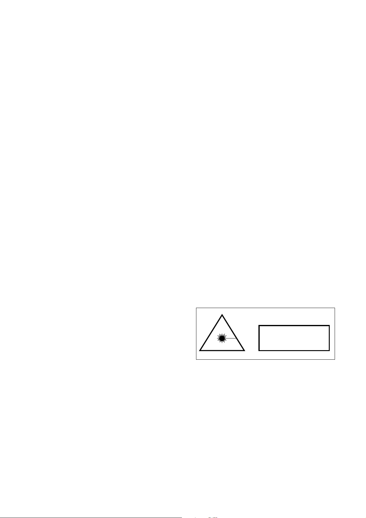
2.3.1 Laser compliance
The system describe d in this manual contains a
laser device. Dep e nding of the emission power of
the laser used in the Starter Kit, the classification
may change.
According to the emission p ower, the laser pr od-
uct meets the following requirements:
CLASS I : . . . . . . . . Emission power < 10 mW
CLASS IIIb : . . . . Emission power > 10 mW
Fig.1: Class I lase r compliance
5
Page 7

Starter Kit Instruction Manual General 6
2.4 Glossary
The following terms, among others, are used in this
Instructions Manual.
2.4.1 Persons
Personnel
Personnel refers to all perso ns who carry out
any activity with the instrumentation and meet the
manufacturer’s requirements a bout personnel to run
those activities and have been therefore author iz e d.
2.4.2 Product
QCL
This is the Quantum Cascade Laser manufactured by Alpes Lasers SA, CH-2001 Neuchˆatel.
Page 8

Starter Kit Instruction Manual General 7
2.5 Typographic conventions
The following styles are used in this manual.
Description style
This style, used in relatio n with a number in illustrations (figures) is preceded by the corresponding number:
Example:
(1) First item.
(2) Second item.
(3) etc...
Commands style
All software commands, buttons, function keys,
windows, icons, options, tabs, check boxes, select
boxes, items, menus, tool bars, sections and fields
used in this documentation will be shown with a
bold italic font.
Example:
The Exit command permits to leave the program.
Procedure style
The steps of a procedure to be carried out step
by step by the personnel are preceeded with num-
bers placed in brackets.
Example:
[1] Set the selector (4) to mode Real◦C.
[2] Check the power supplies +5V and -5V.
The error should be within +/- 50 mV.
Page 9

Starter Kit Instruction Manual General 8
Procedure effects style
The procedur e effects are described by using the
following symbol ,→.
Example:
[1] Click on the Delete Sample icon.
,→ The message Do you really want to
delete the sample ? appea rs.
Cross references style
This style is used to help the personnel to find
other information about the curre nt subject.
Example:
See page x-y.
Troubleshooting s tyle
The complete description with the problem, the
possible cause and the solution will be shown like
described below:
Problem
- Possible cause
√
Solution
List of items style
This style is used to give a list of items.
Example:
• item 1
• item 2
• item 3
Page 10

Starter Kit Instruction Manual General 9
Note style
Used when the personnel attention must be drawn
to a particular operation or information.
Example:
Note: The laboratory housing LLH100 makes
available two outputs giving access t o these voltage.
Caution style
Used to prevent the personnel from any danger
or hazardous situation. Non-compliance with such
instructions may lead to damage parts or environment.
Example:
CAUTION ! Take care about...
Warning style
Used to prevent the personnel from any important danger or hazardous situation. Non-compliance
with such instructions may lead to death or serious
injury.
Example:
! WARNING ! Never open this cover...
Page 11

Chapter 3
Safety Instructions
3.1 Chapter overview
This chapter sets out safety instructions for ensuring safe and trouble-free operation of the system
described in this manual.
3.2 Introduction
3.2.1 Principle
The personnel must have read and understood this
documentation before carrying out any activity whatsoever with the system described in this manual.
In case of unclear information, please contact
the manufacturer or Alpes Lasers SA representative.
3.2.2 Importance of safety instructions
All the safety instructions in this manual must be
carried out in order to avoid injury to persons or
damage to property and the environment.
Similarly, the statutory regulations, measures
for accidents prevention and protection of the environment and the recognized technical rules for
safe and appropriate working practices which are in
force in the country and place of use of the sy stem
must be complied with.
3.2.3 Non-compliance with the safety
regulations
Non-compliance with the safety instructions, statutory and technical regulations may lead to injuries
to persons, or dama ge to property and the environment. Moreover, this will result in loss of warranty.
10
Page 12

Starter Kit Instruction Manual Safety Instr uctio ns 11
3.3 General safety instructions
• Never attempt to use a s ystem for purposes
other than those detailed in this manual.
• Never attempt to use a system in conjunction with other instruments without obtaining prior information and approval from the
manufacturer.
• Never attempt to use spare parts other than
those supplied by the manufacturer.
• If an instrument is to be left unused for any
length of time, protect the instrument against
dust and/or humidity.
3.4 Environmental conditions
• Like any other electrical device, the system
must not be lo c ated near a water tap.
• The instrument must be kept away from potential sources of interference.
• The system must not be exposed to direct
sunlight, heat, dust or excessive humidity (use
only in a clean labor atory environment).
• Take care not to spill liquid on an instrument.
In the event of accidental spillage, proceed as
follows:
[1] Switch off the instrument immediately.
[2] Unplug the instrument from the mains.
[3] Wipe the instrument down with a dry
tissue.
[4] Check all the electrical functions.
• Ensure sufficient ventilation of the instrument
to prevent overheating.
3.5 Compliance and information
In the event of operating faults or other technical
incidents for which a remedy is not described in this
manual, please contact the manufacturer or Alpes
Lasers SA representative immediately.
(http://www.alpeslasers.ch/contacts.htm)
Page 13
Chapter 4
T
P
G
1
2
8
−
T
T
L
P
u
l
s
e
G
e
n
e
r
a
t
o
r
O
F
F
TCU151
O
N
P
o
w
e
T
r
e
m
p
e
r
a
t
u
r
0
e
.
C
2
o
t
n
o
t
2
r
.
o
2
l
µ
l
s
0
e
.
r
5
t
o
1
0
.
5
µ
s
5
t
o
1
0
5
µ
s
0
t
o
2
0
0
n
s
−
−
−
−
−
−
−
−
−
P
e
r
i
o
d
−
−
−
−
−
−
−
−
−
−
D
u
ra
t
i
o
n −
G
a
t
e
I
N
T
r
i
g O
U
T
O
u
t
1
O
u
t
2
5
0
o
h
m
s
5
0
o
h
m
s
5
0
o
h
m
s
m
a
x
6
0
m
A
+
1
2
V
0
V
connected to + hi High Voltage
Pulse on top, Bottom
Output
Current control Max 60V
Power supply 12V
Input
LDD 100
Monitor 20 A/V, Z50 Ohm
3
1
4
2
Description
4.1 Chapter overview
This chapter gives a basic description of the Quantum Cascade Laser Starter Kit system and its composition.
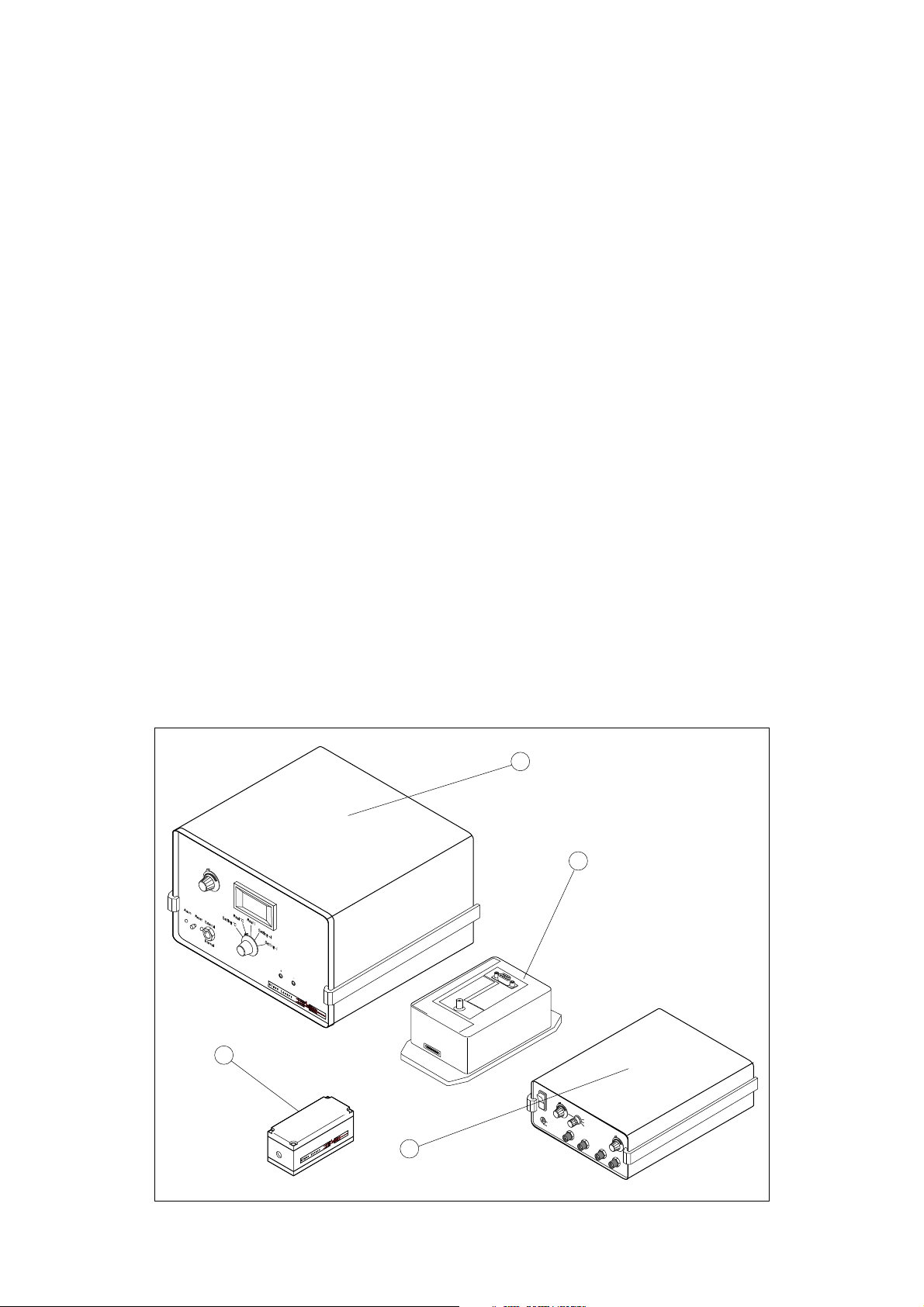
4.2 System Composition
The Quantum Cascade Laser Starter Kit is made
up of the following items:
(1) Laboratory Laser Housing (LLH100)
(2) Temperature Controller (TCU151)
(3) QCL pulse switching unit (LDD100)
(4) QCL pulser timing unit (TPG128)
For operation of the system, the user must provide a stabilized DC power supply capable of delivering DC current that corresponds to the laser
peak current multiplied with the specified duty cycle at the specified LDD100 voltage: refer to the
datasheet of the laser.
CAUTION !
Do not lift TCU151 or TPG128 only on t he top
cover, since this might loosen the connection between the cover and the chassis.
Fig.2: Quantum Cascade Laser Starter Kit
Page 14
Starter Kit Instruction Manual Description 13
1
2
4.3 DFB and FP Quantum Cascade Lasers
4.3.1 Description
Quantum Cascade Lasers (QCL) are unipolar lasers
emitting in the mid-infrared from 4 to 17 microns.
The laser is a ridge of InGaAs and AlInAs grown
on InP providing gain and a Fabry-Perot cavity in
order to build the laser oscillation up. DistributedFeedback(DFB) Quantum Cascade Lasers are then
obtained by adding a grating, forcing the laser to
emit at the target wavelength.
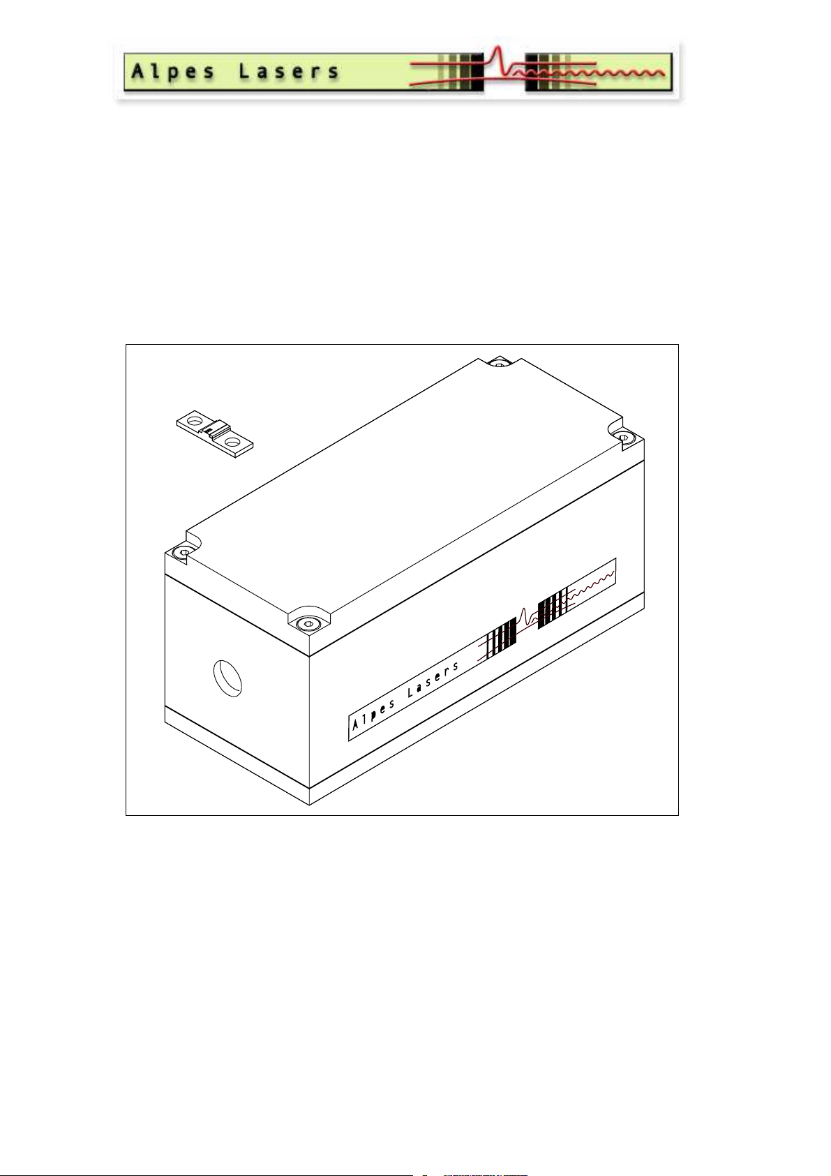
4.3.2 Geometry of QC lasers
Mountings
Lasers exist in two different packages:
• ST mounting (1)
• NS mounting (2)
Axes of QC lasers
The vertical direction is the so called growth dire c tion.
Device are mounted on a copper carrier which
has one or two ceramic pads carrying the bonding
wires. The pads are yellow on top due to a layer of
gold, and white around it and on the sides (colour
of the ceramic). If these pads are placed upwards,
the vertical for the laser is the same as the observer
vertical dire c tion.
If there are two ceramic pads pre sent, they are
named as follows:
Looking onto the front facet with the laser placed
as described above, the pad left of the laser chip is
called ”DN” (for DOWN), the one on the right of
it ”UP”.
Fig.3: ST submount
If no configuration is specified,
the ”DN” pad is used.
Never place the laser upside-down, since this will
damage the bonds connecting the pads to the laser
and possibly the laser itself !
The laser chips mounted on NS submounts provided separately from a LLH100 are supplied in a
round plastic box. For removing the laser from it,
please follow the instructions as described in appendix (appendix 10.2, p.59)
Fig.4: NS submount
Page 15

Starter Kit Instruction Manual Description 14
4.3.3 Specifications
Far field elliptical (FWHM):
Vertical: . . . . . . . . . . . . . . . . . . . . . . . . . . . . . . . . . . . . . . . . . . . . . . . . . . . . . . . . . . . . . . . . . . . . . . . . . . . . . . . .60
Horizontal: . . . . . . . . . . . . . . . . . . . . . . . . . . . . . . . . . . . . . . . . . . . . . . . . . . . . . . . . . . . . . . . . . . . . . . . . . . . . . 40
Operating temperature:
Might vary for each laser, but generally located in the range from -30◦C to +30◦C
Caution !
Before operating the laser at different temperature than specified in the datasheet, please contact
Alpes Lasers SA or a representative. Damages resulting from a non-respect of temperature operating range without approval from Alpes Lasers SA will led to a loss of warranty.
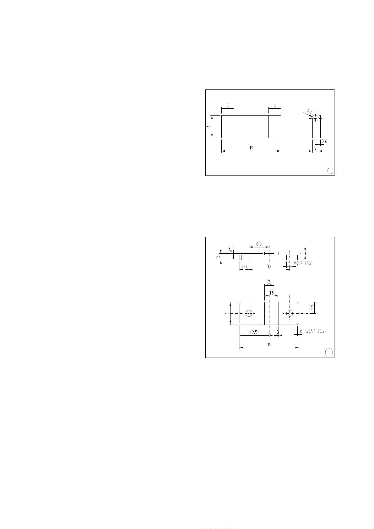
Submount size :
ST mounting: . . . . . . . . . . . . . . . . . . . . . . . . . . . . . . . . . . . . . . . . . . . . . . . . . . . . . . . . . . . . . . 19 x 7 x 2 mm
NS mounting: . . . . . . . . . . . . . . . . . . . . . . . . . . . . . . . . . . . 19 x 7 x 2.5(top of the ceramic pads) mm
Typical lase r position:
Over the submount, centered laterally: . . . . . . . . . . . . . . . . . . . . . . . . . . . . . . . . . . . . . . . . . . . . . 0.2 mm
Inside the sub-mount top surface: . . . . . . . . . . . . . . . . . . . . . . . . . . . . . . . . . . . . . . . . . . . . . . . . . 0.03 mm
Laser emitting facet: . . . . . . . . . . . . . . . . . . . . . . . . . . . . . . . . . . . . . . . . . . . 0.005 - 0.030 x 0.004 mm
◦
◦
3
3
2
Page 16

Starter Kit Instruction Manual Description 15
− −
+
=
+
R1
C1
C2
4.3.4 Electrical model
The QCL can be modelised in a RC circuit.
Electrical model characteristics
The values given below apply for a 10µm
laser wavelength.
Fig.5: Electrical model of QCL
Note: Voltage and resistor values may vary
according to the type of laser.
R1 : . . . . . . . . . . . . . . . . . . . . . . . . . . . . . . . . . . . . . . . . . . 10 to 20Ω when a voltage of 4 to 6 Volts is applied
R1 : . . . . . . . . . . . . . . . . . . . . . . . . . . . . . . . . . . . . . . . . . . . . . . . . . . . . . . . . . . . . . . . . . . 2 to 4Ω up to 10 - 12 Volts
R1 : . . . . . . . . . . . . . . . . . . . . . . . . . . . . . 10 to 20Ω over 12 Volts, after which the laser no longer operates
C1 : . . . . . . . . . . . . . . . . . . . . . . . . . . . . . . . . . . . . . . . . 100pF, capacitor between the anode and the cathode
C2 : . . . . . . . . . . . . . . . . . . . . . . . . . . . . . . . . . . . . . . . . . . . <100pF, depe nding on your mounting of the laser
Page 17
Starter Kit Instruction Manual Description 16
2
1
3
4
6
5
177
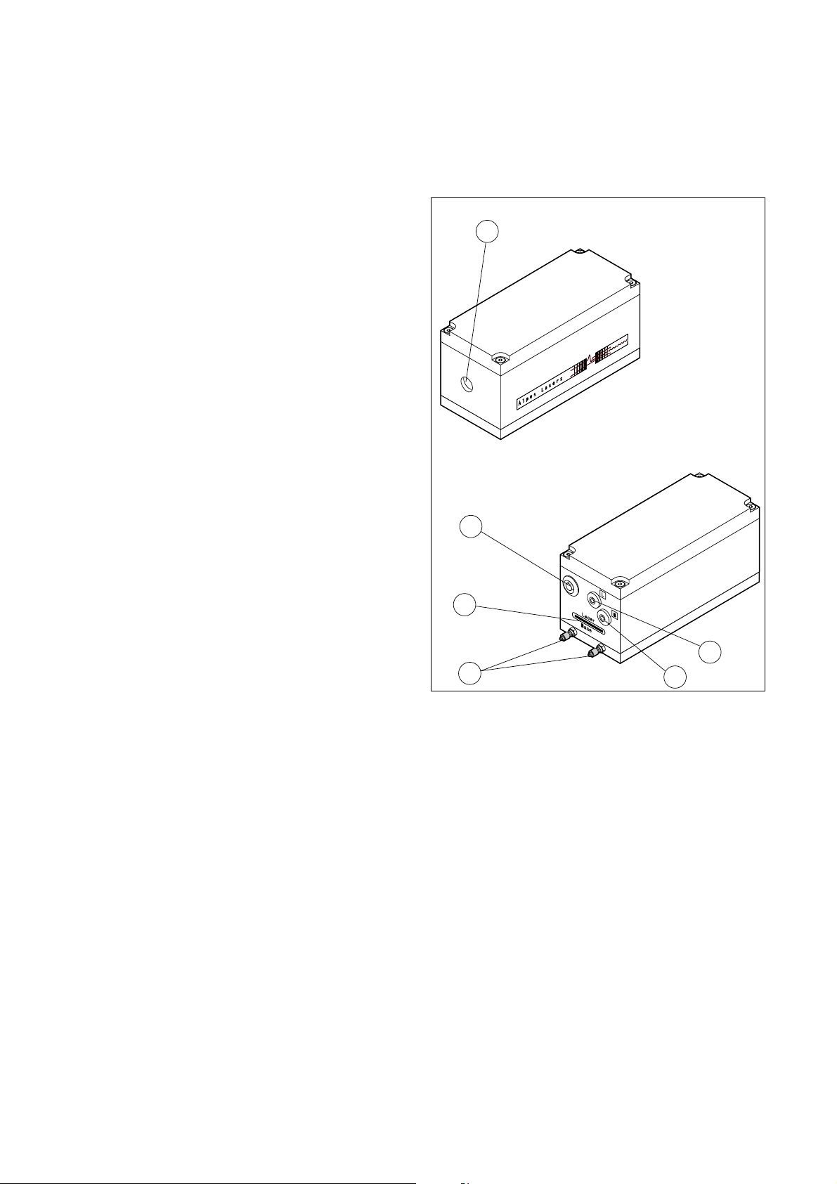
4.4 Laboratory Laser Housing(LLH100)
4.4.1 Description
The Laboratory Laser Housing is a Thermo-Electric
cooled box which encapsulates the Quantum Cascade Laser.
The internal temperature is controlled by a PT100 sensor and heat is dissipated by air or water.
The LLH100 is designed to ease the laser installation or replacement.
LLH100 external view description
The Laboratory Laser Housing is composed of the
following items:
(1) ZnSe coated laser beam window
(2) Peltier connector and PTC sensor
(3) Low impedance connector
(4) Cooling water flow fittings (recommended
flow: 0.25 l/min @ 10-20◦C)
(5) Monitoring base receptacle connector
(6) Monitoring laser connector
Fig.6: Laboratory Laser Housing front and rear view
Page 18
Starter Kit Instruction Manual Description 17
1
2
3
4
5
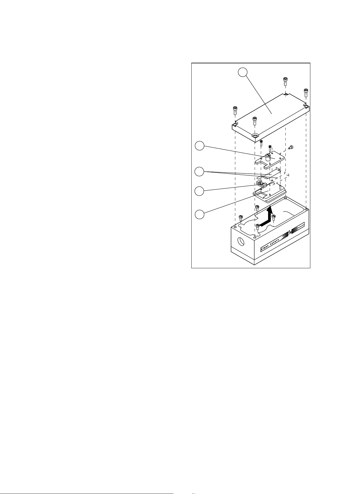
LLH100 internal view
The Laboratory Laser Housing includes the following items:
(1) LLH100 top cover
(2) PET U-shaped holder
(3) Gilded copper contact (UP and DN)
(4) Laser
(5) Laser receptacle
4.4.2 Specifications
Maximum Peltier current
(with water cooling): . . . . . . . . . . . . . . . . . . . . .5A
Lowest reachable temperature
(with water cooling): . . . . . . . . . . . . . . . . . -40◦C
Highest recommended temperature
(due to Peltier limitations): . . . . . . . . . . . 80◦C
Window:
Diameter : . . . . . . . . . . . . . . . . . . . . 12.7 mm
Clear aperture: . . . . . . . . . . . . . . . . . 11 mm
Coating: . . . . . . . . . . . . . . ZnSe, 3 to 12 µm
Temperature measurement: . . . PT100 4 wires
Fig.7: Laboratory Laser Housing internal view
Page 19

Starter Kit Instruction Manual Description 18
4
5
6
1
2
3
4.4.3 Thermo-Electric Cooler ( T EC)
and P T 100 connections
The pin 1 is recognised by a circle around it and
a thin noon ended circle starts from pin one and
turns around the pins until pin 6.
(1) Pin 1: +Peltier element
(2) Pin 2: - Peltier element
(3) Pin 3: I+ PT100
(4) Pin 4: Sens + PT100
(5) Pin 5: Sens - PT100
(6) Pin 6: I- PT100
Specifications of the Peltier connector
Vacuum case plug reference: . . . . . . . LEMO #
HGG.1b.306.CLLPV.
Cable plug reference: . . . . . . . . . . . . . LEMO #
FGG.1b.306.CLAD72Z.
Fig.8: Front view of the Peltier connector
Plastic protection for the cable: . . .LEMO #
GMA.1b.065.DG.
Cable:
Diameter : . . . . . . . . . . . . . . . . . . . . . 5.8 mm
Section : 6 x 0.25 mm (2 x 0.25 for each
Peltier connections)
or
Diameter : . . . . . . . . . . . . . . . . . . . . . 7.2 mm
Section : 10 x 0.25 mm (2 x 3 x 0.25 for
Peltier connections)
Page 20

Starter Kit Instruction Manual Description 19
4.4.4 Measurement connection
These connections give access to the voltage on the
laser.
The ”L” connection is connected AC coupled to
the cathode of the laser through a divider by ten.
The end of cable must be 50Ω terminated for accurate measurement. The ”B” is connected the same
to the anode of the laser (Base Receptacle).
By using the math trace of an oscilloscope showing the ”L” channel minus the ”B”, one can get the
voltage on the laser.
This measurement is more accurate than the information obtained from the LDD100 measurement
unit.
For more details, refer to LDD100 Diagram Block
on page ??.
Specifications of the measurement connector
Vacuum case plug reference: . . . . . . . LEMO #
HGP.00.250.CTLPV
Cable plug reference: . . . . . . . . . . . . . . LEMO #
FFS.00.250.CTCE31
Cable :. . . . . . . . . . . . . . . . . . . . . . . . . . . . . . .RG174
Page 21

Starter Kit Instruction Manual Description 20
1
2
3
connected to + hi High Voltage
Pulse on top, Bottom
Output
Current control Max 60V
Power supply 12V
Input
LDD 100
Monitor 20 A/V, Z50 Ohm
4.5 QCL pulser switching unit(LDD100)
4.5.1 Description
The switching unit is based on dedicated power
MOS-FETS with up to 30A current compatibilities
and 60V. In addition, the circuit is limited in power
dissipation by the cooling o f the unit. During operation, the temperature of the case should not exceed 60C. While powering usual QC diodes, these
limitations are never reached because the laser has
usually much lower power ratings.
! WARNING !
An important feature of this unit is that
both lines going to the laser are ”HOT”, i.e.
have a postive voltage respective to the case.
this feature should be kept in mind when designing the laser holder. This one should be
insulated and have a low capacitance(< 100pF)
towards the ground.
The QCL pulse switching unit is composed of
the following connectors:
(1) Low impedance connector
(2) Drive c able connector
(3) Monitoring BNC connector
4.5.2 Specifications
Voltage : . . . . . . . . . . . . . . . . . . . . . . max 60 VDC
Current : . . . . . . . . . . . . . . . . . . . . . . max 30 ADC
Repetition rate : . . . . . upto 1MHz, limited by
average current
Rising/falling edge: . . typical 8ns (max 12ns)
Minimum pulse width: . . . . 16ns, typical 20ns
Maximum pulse width: 1µs, limited by power
supply
Support power: . . . . . . . . . . . . given by TPG128
Trigger IN: . . . . . . . . . . . . . . . . . . . . . . . . TTL 50Ω
Fig.9: QCL pulser switching unit front and rear view
Propagation delay: . . . . . . typical 35ns <40 ns
Size: . . . . . . . . . . . . . . . . . . . . . 90 x 130 x 50 mm
3
! WARNING !
The connection between the laser and the
QCL pulse switching unit is floating. It must
not be connected wi th the ground.
Page 22

Starter Kit Instruction Manual Description 21
4.6 QCL pulse switching measuring unit
4.6.1 Generalities
The measuring circuit contained in the LDD100
provides information about various laser pulse parameters (peak voltages, supply voltages, duty cycle, frequency). They are only estimated values,
since exact measurement of short and strong pulses
with diodes and averaging circuitry is difficult.
Keep in mind that you should always measure
the voltages on the LLH100 if you need accurate
time and voltage data (see final paragraph). However, these data are useful for monitoring and surveillance purposes, and to give a rough estimation of
the current parameters.
4.6.2 Measured voltages
• UHV: 1/2 of the average voltage, respective
to VHT (user supplied high voltage)
• ULH: 1/2 of the average laser anode voltage,
respective to VHT
• ULL: duty cycle dependent peak laser cathode
voltage, respective to VHT
• UD: duty cycle dependent peak transistor drain
voltage, respective to VHT
• UPI: 1/2 average internally reshaped drive voltage, respective to ground
• UPT: 1/2 average of a 37ns fixed length pulse,
respective to ground
4.6.3 Timing data
Pulse frequency calculation
UPT can be used to calculate the pulse frequency
as follows:
f = f
2UP T −ν
0
ν
Where f0is a frequency constant, v
v
are the TTL pulser voltage limits.
P high
P low
P high−νP low
P low
and
Actual values: f0=
1
37
ns , v
P low
=0.01V, v
P high
=5V
Page 23

Starter Kit Instruction Manual Description 22
Duty cycle calculation
UPI can be used to calculate the duty factor as
follows:
2UP I −ν
df =
ν
P low
P high−νP low
with v
P low
and v
P high
as above.
To get the real duty cycle, df must be corrected
as follows:
dc = f
LDD
df = f
LDD
2UP I −ν
ν
P low
P high−νP low
to compensate for sys tematic errors in the LDD100.
Actual value is f
LDD
= 1.1
4.6.4 Laser peak current
The laser peak curre nt can be calculated by the
measurement of the current through the series resistor Rs. This is provided by the values ULL and
UD, which are rectifier outputs. To correct for the
duty cycle, the rectifier values have to be taken into
account with the following fo rmula for a correction
factor:
p = 1 +
Rds
Rcdc
where Rds and Rc are resistors in the rectifier
circuit, dc is the duty cycle calculated as in the
preceding paragraph. Actual values are Rds=10kΩ
and Rc=10MΩ.
The corrected values for the peak laser cathode
and transistor drain voltage are then given as follows:
ULL
UD
= pU LL + U ds
peak
= pU D + U ds
peak
where Uds is the voltage drop across the rectifier diode, actual value Uds=0.25V.
Finally, the laser peak current is then given by:
I
peak
ULL
=
peak
−UD
Rs
peak
where Rs is the series resis tor, a c tua l value Rs
=0.85Ω.
Page 24

Starter Kit Instruction Manual Description 23
4.6.5 Laser peak voltage
The laser peak voltage is given by:
U
= 2U LH − U LL
peak
peak
where U LL
is the corrected peak value of
peak
ULL as calculated in the previous paragraph.
4.6.6 Average dissipation
The average therma l dissipation of the laser is given
by:
where U
peak
P = U
and I
peakIpeak
peak
dc
are the peak values of
laser voltage and current as calculated in the previous paragraphs, and dc is the (corrected) duty
cycle.
4.6.7 Ac c uracy considerations
The duty cycle (corrected) is accurate to about 5%
for pulse lengths in the range 50ns to 150ns and
pulse periods in the range 1µs to 10µs. Especially
for short pulses, the accuracy can deteriorate to over
10%. These calculations and data are compared to
the pulse lengths measured via the BNC connector of the LDD100. The TTL pulses generated by
the TPG128 are always longer, due to losses in the
LDD100.
Since the other calculations depend on the duty
cycle data, they are in general even less accurate.
The rectifier circuits used to measure the peak voltages show nonlinearities especially around 13V, and
therefore the voltage may seem to saturate at a
certain current for certain lasers. In addition, the
change in laser impedance around thresho ld can
generate remarkable nonlinearities compared to the
above calculations.
If you need accurate values, proceed as follows:
[1] Measure laser peak voltage, frequency and
duty cycle using a two-channel oscilloscope
(connected to the LEMO jacks of the LLH100)
in differential mode.
[2] Measure average current into the laser using the value given by the HV supply (or by
an attached RMS ampermeter).
[3] Calculate peak current by dividing average
current by the duty cycle.
Page 25

Starter Kit Instruction Manual Description 24
T
P
G
1
2
8
−
T
T
L
P
u
l
se
G
e
n
e
r
a
t
o
r
O
F
F
O
N
P
o
w
e
r
0
.
2
t
o
2
.
2
µ
s
0
.
5
t
o
1
0
.
5
µ
s
5
t
o
1
0
5
µ
s
0
t
o
2
0
0
n
s
−
−
−
−
−
−
−
−
−
P
e
r
i
o
d
−
−
−
−
−
−
−
−
−
−
D
u
r
a
t
i
o
n
−
G
a
t
e
I
N
T
r
i
g
O
U
T
O
u
t
1
O
u
t
2
5
0
o
h
m
s
5
0
o
h
m
s
5
0
o
h
m
s
m
a
x
6
0
m
A
+
1
2
V
0
V
4.7 QCL pulser timing unit (TPG128)
4.7.1 Description
The QCL pulser timing unit is designed to control
the QCL pulser switching unit.
It provides TTL pulses on 50Ω on two indep e ndent outputs. The pulse duration is adjustable from
0 to 200ns. The interval between pulses can be adjusted between 200ns and 105µs in 3 ranges.
A TTL level Gate in input and Trigger out
output have also been included. The trigger precedes the output pulse by about 100ns.
The QCL pulser timing unit includes the +12VDC
power supply needed by the QCL pulser switching
unit by means of a Lemo 00 connector with the
+12V on the centre wire.
! Warning !
Although the pulser system is capable of
delivering pulses with lengths up to 200 ns,
and duty cycles up to 50%, the laser may not
withstand this! The laser shall only be operated under conditions as specified in the
datasheet or by Alpe s Lasers directly: all
other operation may result in destruction of
the laser and loss of warranty.
Fig.10: QCL pulser timing unit
Limitations
Caution !
The generator can not operate with a 200 ns long
pulse at a 200ns repetition interval, therefore it is
limited in duty factor.
The following limitations apply:
4.7.2 Specifications
Voltage :. . . . . . . . . . . . . . . . . . . . . . . . .220V-240V
Frequency : . . . . . . . . . . . . . . . . . . . . . 50Hz-60Hz
Output voltage (for switching unit):+12VDC
Output max current (for switching unit):150mA
Delay between pulses:
. . . . . . . . . . . . . . . . . . . . . . . .200 ns to 2.2 µs
. . . . . . . . . . . . . . . . . . . . . . 500 ns to 10.5 µs
. . . . . . . . . . . . . . . . . . . . . . .5.1µs to 105.1 µs
trigger and logic output signals: . . . 50Ω TTL
driver circuit (74128)
gate level : . . . . . . . . . . . . . . . . . . . . . . . . . . . . . TTL
Maximum duty cycle: 50% (if larger cycles are
needed, the LDD100 should be fed by an external 12V power supply, not the one provided in the
TPG128, or else the fuse in the TPG128 may blow).
T=400ns: . . . . . . . . . . . . . . . . . . . . t max = 20 0ns
T=300ns: . . . . . . . . . . . . . . . . . . . . t max = 20 0ns
T=250ns: . . . . . . . . . . . . . . . . . . . . t max = 15 0ns
T=200ns: . . . . . . . . . . . . . . . . . . . . t max = 10 0ns
Page 26

Starter Kit Instruction Manual Description 25
TCU151
T
e
m
p
e
r
a
t
u
r
e
C
o
n
t
r
o
l
l
e
r
A
l
a
r
m
R
e
s
e
t
E
x
t
e
r
n
a
l
I
n
t
e
r
n
a
l
R
e
a
l
I
Re
a
l
C
S
e
t
t
i
n
g
C
S
e
t
t
i
n
g
+
I
S
e
t
t
i
n
g
−I
+
−
1
2
1
7
3
4
5
6
4.8 QCL temperature controller(TCU151)
4.8.1 Description
The TCU151 is used to co ntrol the laser’s temperature inside the Laboratory Laser Housing.
It uses a PT100 se ns or to measure the tempe rature of the cold plate and maintains a pre-set temperature either from a front panel knob or from a
user supplied voltage.
4.8.2 Specifications
Voltage: . . . . . . . . . . . . . . . . . . . . . . . 120 -240V AC
Frequency: . . . . . . . . . . . . . . . . . . . . . . . . . 50-60 Hz
Fuse:
. . . . . . . . . . . . . . . . . . . . 1.6 A T (220-240V)
. . . . . . . . . . . . . . . . . . . 3.2 A T (110 -120V)
Fig.11: TCU151 temperature controller
Peltier current maximum: . . . . . . . . . . . . . . . . 5A
Temperature control range: . -65◦C to 65◦C
Temperature measurement: . . . PT100 4 wires
Temperature monitor: . . . . 10mV/◦C, Zout =
200Ω
In addition, allow for 15 min. warm-up of
TCU151 to get stable readings
External driving temperature: . -6.5V to 6.5V
(-65◦C to 65◦C), Zin =1MΩ
4.8.3 Peltier and PT100 connections
The rear connector pinout is listed according to the
following items:
(1) Pin 1: +Peltier element
(2) Pin 2: - Peltier element
(3) Pin 3: +I PT100
(4) Pin 4: +Sense PT100
(5) Pin 5: -Sense PT100
(6) Pin 6: -I PT100
(7) Pin GND: Ground
Fig.12: TCU151 Peltier Connector
Page 27

Chapter 5
T
P
G
1
2
8
−
T
T
L
P
u
l
s
e
G
e
n
e
r
a
t
o
r
O
TCU151
F
F
O
N
P
o
T
w
e
e
m
r
p
e
r
a
t
u
r
e
0
C
.
o
2
n
t
t
o
r
2
o
.
l
2
l
m
e
s
r
0
.
5
t
o
1
0
.
5
m
s
5
t
o
1
0
5
m
s
0
t
o
2
0
0
n
s
−
−
−
−
−
−
−
−
−
P
e
ri
o
d
−
−
−
−
−
−
−
−
−
−
D
u
r
a
t
i
o
n
−
G
a
t
e
I
N
T
ri
g
O
U
T
O
u
t
1
O
u
t
2
5
0
o
h
m
s
5
0
o
h
m
s 5
0
o
h
m
s
m
a
x
6
0
m
A
+
1
2
V
0
V
connected to + hi High Voltage
Pulse on top, Bottom
Output
Current control Max 60V
Power supply 12V
Input
LDD 100
Monitor 20 A/V, Z50 Ohm
1
2
3
4
5
7
6
Installation
5.1 Chapter overview
This chapter describes the installation and the connection of the QCL Starter Kit. It also explains the
operating checks before the normal use.
5.2 General
The setup procedure s outlined below must be followed meticulously to ensure that QCL Starter Kit
operates correctly and safely.
5.3 Packing list
5.3.1 Standard items
The standard starter Kit is supplied with the following items:
(1) QCL pulse timing unit (TPG128)
(2) CPL100 cable
(3) QCL pulse switching unit (LDD100)
(4) Low impedance line (LBI100)
(5) Laboratory Laser Housing (LLH100)
(6) CTL100 cable
(7) Temperature controller (TCU151)
(8) Power cords
1 Instructions manual
Fig.13: QCL Starter Kit packing list
26
Page 28

Starter Kit Instruction Manual Installation 27
0
1
U
S
E
O
N
L
Y
W
I
T
H
2
5
0
V
F
U
S
E
S
/
E
M
P
L
OY
E
R
U
N
I
Q
U
E
M
E
N
T
A
V
E
C
D
E
S
F
USI
B
L
E
S
DE
2
5
0
v
1
1
0
−
1
2
0
V
2
2
0
−
2
4
0
V
U
T
P
U
T
M
a
x:
1
5
V
/
6
A
M
O
N
I
T
O
R
I
N
G
10
m
V
/
C
Z
o
ut
:
200
ohm
E
x
t
er
n
al
R
e
f
.
1
00
m
V
/
C
Z
i
n:
1
M
o
hm
I
nt
er
l
o
c
k
i
ng
1
O
I
USEONLY WITH250V
FUSES/ EMPLOYER
UNIQUEMENTAVEC
DESFUSIBLESDE250v
110−120V
2
2
0−2
4
0
V
2
3
5.4 Setting the appropriate AC
voltage on TCU151
The TCU151 temp e rature controller works on 110/120V
or 220/240V if the fuse holder is oriented in the appropriate position.
Note: There are two rates:
110-120V, 60Hz (USA)
220-240V, 50Hz (Europe)
5.4.1 Procedure
To set the appropriate voltage on the TCU151 temperature controller, proceed as fo llows:
[1] Pull out the fuse holder (1) from the socket.
[2] Verify the orientation of the fuse holder to
get the appropriate voltage. The arrow on the
fuse holder (3) should correspond to the mark
on the socket (2).
[3] Insert the fuse holder (1) into the socket.
Fig.14:TCU151 rear panel
Fig.15 : Setting the appropriate AC voltage rate
Page 29

Starter Kit Instruction Manual Installation 28
T
P
G
1
2
8
−
T
T
L
P
u
l
s
e
G
e
n
e
r
a
t
o
r
O
TCU151
F
F
O
N
P
o
T
w
e
e
m
r
p
e
r
a
t
u
r
e
0
C
.
o
2
n
t
t
o
r
2
o
.
l
2
l
m
e
s
r
0
.
5
t
o
1
0
.
5
m
s
5
t
o
1
0
5
m
s
0
t
o
2
0
0
n
s
−
−
−
−
−
−
−
−
−
P
e
r
i
o
d
−
−
−
−
−
−
−
−
−
−
D
u
r
a
t
i
o
n
−
G
a
t
e
I
N
T
r
i
g
O
U
T
O
u
t
1
O
u
t
2
5
0
o
h
m
s
5
0
o
h
m
s 5
0
o
h
m
s
m
a
x
6
0
m
A
+
1
2
V
0
V
connected to + hi High Voltage
Pulse on top, Bottom
Output
Current control Max 60V
Power supply 12V
Input
LDD 100
Monitor 20 A/V, Z50 Ohm
2
1
5.5 Installing the starter Kit
5.5.1 Before beginning
Make sure that the following devices are turned
OFF:
• TPG128
• TCU151
• User DC power supply
5.5.2 Procedure
To install the QCL Starter Kit, proce e d as follows:
[1] Plug the low impedance line into the LLH100
connector (2). The line connector is coded.
CAUTION ! Pay attention about the connection’s polarity. The laser must be floating
from ground for both anode and cathode.
[2] Plug the low impedance line into the QCL
pulser switching unit low impedance output
(1) paying attention for the polarity.
Fig.16: Installing the Quantum Cascade Laser Starter Kit
Page 30

Starter Kit Instruction Manual Installation 29
T
P
G
1
2
8
−
T
T
L
P
u
l
s
e
G
e
n
e
r
a
t
o
r
O
TCU151
F
F
O
N
P
o
T
w
e
e
m
r
p
e
r
a
t
u
r
e
0
C
.
o
2
n
t
t
o
r
2
o
.
l
2
l
m
e
s
r
0
.
5
t
o
1
0
.
5
m
s
5
t
o
1
0
5
m
s
0
t
o
2
0
0
n
s
−
−
−
−
−
−
−
−
−
P
e
r
i
o
d
−
−
−
−
−
−
−
−
−
−
D
u
r
a
t
i
o
n
−
G
a
t
e
I
N
T
r
i
g
O
U
T
O
u
t
1
O
u
t
2
5
0
o
h
m
s
5
0
o
h
m
s 5
0
o
h
m
s
m
a
x
6
0
m
A
+
1
2
V
0
V
connected to + hi High Voltage
Pulse on top, Bottom
Output
Current control Max 60V
Power supply 12V
Input
LDD 100
Monitor 20 A/V, Z50 Ohm
6
9
8
7
3
1
2
3
5
[3] Plug the cable (3) onto the LDD100(4).
[4] Plug the +12VDC connector (1) into the
TPG128 (9).
[5] Plug the trigger BNC connector (2) into
the TPG128 (9) Out 1 or Out 2 outptut.
CAUTION ! The unit must be floating.
[6] Plug the banana cables (8) (red a nd black)
into the DC power supply unit.
[7] Plug the LEMO connector (6) onto the
LLH100 module (5) and the connector (7) o nto
the TCU151 unit.
[8] Plug the cooling water tubing if available.
CAUTION ! If no water cooling is available, pay attention to the LLH100 module case
temperature, and be careful of either reducing
heat dissipation or providing air cooling to the
unit.
Fig.17: Connecting Starter Kit
Page 31

Chapter 6
T
P
G
1
2
8
−
T
T
L
P
u
l
se
G
e
n
e
r
a
t
o
r
O
F
F
O
N
P
o
w
e
r
0
.
2
t
o
2
.
2
µ
s
0
.
5
t
o
1
0
.
5
µ
s
5
t
o
1
0
5
µ
s
0
t
o
2
0
0
n
s
−
−
−
−
−
−
−
−
−
P
e
r
i
o
d
−
−
−
−
−
−
−
−
−
−
D
u
r
a
t
i
o
G
a
t
e
I
N
T
r
i
g
O
U
T
O
u
t
1
O
u
t
2
5
0
o
h
m
s
5
0
o
h
m
s
5
0
o
h
m
s
m
a
x
6
0
m
A
+
1
2
V
0
V
6
1
2
3
9
8
7
5
4
Use
6.1 Chapter overview
This chapter describes how to use the QCL Starter
Kit. It also explains the functionalities of the TPG128
and the Temperature Controller (TCU151).
6.2 QCL pulse timing unit command description
The Quantum Cascade Laser is controlled by the
QCL pulse timing unit TPG128. The TPG128 front
panel is composed of the following items:
(1) Power ON/OFF switch.
(2) Period fine 10 turns potentiometer.
(3) Period range 3 positions switch.
(4) Pulse duration 10 turns potentiometer.
(5) BNC 50Ω TTL pulse 2 output.
(6) BNC 50Ω TTL pulse 1 output.
(7) BNC 50Ω TTL Trig OUT.
(8) BNC TTL Gate IN.
(9) LEMO 00 12VDC output (for LDD100).
Fig.18: TPG128 front panel
30
Page 32

Starter Kit Instruction Manual Use 31
0
1
U
S
E
O
N
L
Y
W
I
T
H
2
5
0
V
F
U
S
E
S
/
E
M
P
L
OY
E
R
U
N
I
Q
U
E
M
E
N
T
A
V
E
C
D
E
S
F
USI
B
L
E
S
DE
2
5
0
v
1
1
0
−
1
2
0
V
2
2
0
−
2
4
0
V
U
T
P
U
T
M
a
x
:
1
5
V
/
6
A
M
O
N
I
T
O
R
I
N
G
1
0
m
V
/
C
Z
o
u
t
:
2
0
0
o
h
m
E
x
t
e
r
n
a
l
R
e
f
.
1
0
0
m
V
/
C
Z
i
n
:
1
M
o
h
m
I
n
t
e
r
l
o
c
k
i
n
g
9
12
11
10
8
TCU151
T
e
m
p
e
r
a
t
u
r
e
C
o
n
t
r
o
l
l
e
r
A
l
a
r
m
R
e
s
e
t
E
x
t
e
r
n
a
l
I
n
t
e
r
n
a
l
R
e
a
l
I
R
e
a
l
C
S
e
t
t
i
n
g
C
S
e
t
t
i
n
g
+
I
S
e
t
t
i
n
g
−
I
+
−
1
2
3
4
5
6
7
6.3 TCU151 command description
The internal temperature of the LLH100 is driven
by the TCU151 unit.
The Temperature Controler front and rear pan-
els are composed of the following items:
(1) Set Temperature 5 turns potentiometer:
Allows to set the internal temperature reference.
(2) LCD 3 digits display: Used to display either the actual sensor or reference temperature/current.
(3) Switch to select which temperature or current signals to display.
(4) Alarm display LED.
(5) Alarm reset switch.
(6) Switch which selects between the internal
and the remote temperature reference.
(7) Setting Current adjustment potentiometers.
(8) Power ON/OFF fuse combined main switch.
(9) To LLH100: Amphenol connector for LLH10 0
temperature control.
Fig.19: TCU151 temperature controler front panel
(10) Interlock BNC connector.
(11) External reference BNC connector.
(12) Monitoring: BNC connector providing
the temperature of the sensor as 10mV/◦C
signal.
Fig.20: TCU151 temperature controler rear panel
Page 33

Starter Kit Instruction Manual Use 32
TCU151
T
e
m
p
e
r
a
t
u
r
e
C
o
n
t
r
o
l
l
e
r
A
l
a
r
m
R
e
s
e
t
E
x
t
e
r
n
a
l
I
n
t
e
r
n
a
l
R
e
a
l
I
R
e
a
l
C
S
e
t
t
i
n
g
C
S
e
t
t
i
n
g
+
I
S
e
t
t
i
n
g
−
I
+
−
1
2
3
5
4
0
1
U
S
E
O
N
L
Y
W
I
T
H
2
5
0
V
F
U
S
E
S
/
E
M
P
L
OY
E
R
U
N
I
Q
U
E
M
E
N
T
A
V
E
C
D
E
S
F
USI
B
L
E
S
DE
2
5
0
v
1
1
0
−
1
2
0
V
2
2
0
−
2
4
0
V
U
T
P
U
T
M
a
x
:
1
5
V
/
6
A
M
O
N
I
T
O
R
I
N
G
1
0
m
V
/
C
Z
o
u
t
:
2
0
0
o
h
m
E
x
t
e
r
n
a
l
R
e
f
.
1
0
0
m
V
/
C
Z
i
n
:
1
M
o
h
m
I
n
t
e
r
l
o
c
k
i
n
g
6
7
6.4 Laser utilisation
6.4.1 Overview
In order to insure a correct use and and an appropriate lifetime to the laser, it is recommended to proceed according a specific order as below:
• Start water flow to cool the LLH100.
• Turn on the temperature controller and set
the desired temperature.
• Start the pulse ge nerator.
• Switch on the power supply.
6.4.2 Proceedings
To use the Quantum Cascade Laser, proceed as follows:
[1] Make sure tha t the laser has been installed
properly (see page 38.
[2] If available, turn on the water on the LLH100
module.
CAUTION ! If water is not available, check
the LLH100 module temperature until desired
operating temperature is reached. The unit
has a reduced laser temperature range under
reduced heat sinking conditions. The unit may
Fig.21: Starting the TCU151
become very hot, overheat and be destroyed.
A radiator and possibly a fan might be necessary to increase the laser operating temperature range.
[3] Turn on the TCU151 instrument (6).
Note: Set the desired temperature by first pushing the switch (3) to Setting◦C to display the
objective temperature and turn the 5 turn knob
(1) to change it. Turning the switch (3) to
Real◦C, the display shows the present temperature.
Note: To remote control the LLH100 temperature, set the switch (5) to external and provide
a voltage on the External reference (7) from
-6.5V (-65◦C) to + 6.5V (+65◦C).
[4] Plug the banana cables into the power supply unit and set output voltage to zero and
the compliance current to 100mA if pulsing a
QCL.
Fig.22: TCU151 remote control
Page 34

Starter Kit Instruction Manual Use 33
T
P
G
1
2
8
−
T
T
L
P
u
l
se
G
e
n
e
r
a
t
o
r
O
F
F
O
N
P
o
w
e
r
0
.
2
t
o
2
.
2
m
s
0
.
5
t
o
1
0
.
5
m
s
5
t
o
1
0
5
m
s
0
t
o
2
0
0
n
s
−
−
−
−
−
−
−
−
−
P
e
r
i
o
d
−
−
−
−
−
−
−
−
−
−
D
u
r
a
t
i
o
G
a
t
e
I
N
T
r
i
g
O
U
T
O
u
t
1
O
u
t
2
5
0
o
h
m
s
5
0
o
h
m
s
5
0
o
h
m
s
m
a
x
6
0
m
A
+
1
2
V
0
V
8
9
10
11
[5] Turn the TPG128 ON (8) and set the pulse
period to 2.0 and the range to 0.5 to 10.5 µs
(medium), co rresponding to a period length
of about 2.5us, or to the values specified on
the datasheet or by Alpes Lasers.
[6] Set the pulse duration (11) to 3.0, corresponding to a pulse length of about 50ns, or
to the values specified on the datasheet or by
Alpes Lasers.
[7] Verify laser cabling, power meter range
set corresponding to the power range of the
laser (specified in the datasheet), zeroed and
aligned.
[8] Turn the HV power supply ON, then the
TPG128 ON, and slowly increase the HV output voltage (but not hig her than specified in
the datasheet of the laser!)
Fig.23: Starting the TPG128
[9] If available, monitor the averaged output
to avoid overloading the laser. In any case
place one probe on both the anode and the
cathode of the laser and view it with an oscilloscope.
[10] Subtract the two traces and you get the
voltage across the laser that should not be
more than the specified max voltage.
Note: The laboratory housing LLH100 makes
available two outputs giving access to these
voltages (see documentation).
[11] Set the desired pulse and period length as
specified in the datasheet or by special agreement with Alpes Lasers.
Page 35

Starter Kit Instruction Manual Use 34
0
1
Z
i
n
:
1
M
o
h
m
I
n
t
e
r
l
o
c
k
i
n
g
1
A
l
a
r
m
R
e
s
e
t
E
x
t
e
r
n
a
l
I
n
t
e
r
n
a
l
2
3
6.5 Interlock utilisation
The temperature controller is designed with an builtin interlock (1). This function is activated when a
fault occurs on the TCU151 controller (over-temperature,
over-current, etc.).
The interlock is by default a NC (Normally Close)
relay c ontact.
CAUTION ! It is also possible to set the Interlock as a NO (Normally Open) contact. For more
details about the settings, see the procedure on page
42.
6.5.1 Before beginning
In order to recover the temperature controller from
an interlock event, please pay attention about the
following points:
• Lo cate the fault which caused the interlock
and fix it.
• Wait until the temperature driven by the TCU151
is lower than the max imum.
6.5.2 Procedure Interlock utilisation
To reset the temperatur e controller from an interlock event, proceed as follows:
[1] Press the RESET button (3) on the TCU151
front panel
,→ The interlock is re set and the red LED
ALARM (2) should be off.
Fig.24: Interlock BNC connector
Fig.25: Reseting the interlock
Page 36

Chapter 7
Troubleshooting
7.1 Chapter overview
This chapter sets out troubleshooting instructions
for ensuring safe and trouble-free operation of the
Quantum Cascade Laser Starter Kit system.
7.2 Principle
The personnel must have read and understood this
documentation before carrying out any activity whatsoever with the Quantum Cascade Laser Starter
Kit. In case of unclear information, please contact
the distributor.
The power supply reaches max cur-
rent for a very low voltage
- The low impedance line or the QCL is
shorted to ground.
√
Check the cabling.
√
Replace the laser if necessary.
- The DC power supply is NOT floating.
√
Change the cabling in order to leave
the laser floating.
- The laser tightening device is to o tight-
ened and the QCL laser is shorted to
ground.
√
Loose the laser fixture device.
35
Page 37

Starter Kit Instruction Manual Troubleshooting 36
Laser draws current but gives no
light
- The laser may be reversed polarized (it
is not a desirable situation but does generally not destroy the laser).
√
Check the polarity of the connection.
- The polarity is right. It draws too much
current and the power meter is misaligned.
√
Reduce the current at the maximum
specified for the operating temperature.
√
Check power meter alignement and
scale.
- The QCL laser is not used with the LLH
and is grounded.
√
Check that there is no short-circuit on
the circuit.
The laser does not draw current
- There is no contact with the laser.
√
Check that the gilded copper contact
is present and properly mounted.
√
Tighten the PET U-shaped holder in
order to effective the contact with the
laser by means of the POM fixing screws.
√
Check the connections on the LLH.
Measure the input resistance with an ohmmeter between the Laser connector and
the Base receptacle connector.
Page 38

Chapter 8
Maintenance
8.1 Overview
This chapter describes all procedures of maintenance and calibration for the QC L starter Kit. The
procedures described herein must be performed by
personnel trained on the electronic field, with acceptance by Alpes Lasers, o therwise the warranty
will be lost.
Note: The TTL Pulse Generator (TPG128) and
the Temperature Controller (TCU151) are calibrated
in factory.
8.1.1 How to remove the covers of
TCU151 and TPG128
Pull off the light gray plastic pieces of the side of the
front and back plates. Lift off the light gray plastic
shades form the side of the box, which gives access
to the screws holding the top and bottom covers.
37
Page 39

Starter Kit Instruction Manual Maintenance 38
2
3
4
5
1
8.2 Replacement procedures
8.2.1 Quantum Cascade Laser replace-
ment
Before beginning
[1] Switch the QCL Starter Kit OFF
Material needed
• 1 set of Allen keys.
• 1 ohmmeter.
• 1 QCL laser.
• a pair of tweezers.
Procedure
To replace the Quantum Cascade Laser, proceed as
follows:
[1] Remove the top cover (2) of the Laboratory
Laser Housing (LLH100) by unscrewing the
screws (1)
[2] Remove the PET U-shaped holder (5) by
unscrewing the fixing screws (3)
CAUTION ! Pay attention NOT to drop the
laser!
[3] Remove the laser (4). Hold the laser on
the gilded ceramic pads with the tweezers pins
along the axis of the largest leng th of the copper submount
! WARNING ! Take especially care not
to touch the active region of the laser
or the wire bonds!
Fig.26: Removing the laser
Page 40

Starter Kit Instruction Manual Maintenance 39
4
2
1
3
5
6
[4] Install the new laser (4) into the holder
using small tweezers ( 0.5cm aperture).
[5] Hold the laser (4) on the gilded ceramic
pads with the tweezers pins along the axis of
the largest length of the copper submount.
[6] Plac e it in the receptacle parallel to the
window.
! Warning ! Avoid hitting the laser chip
facet o n the case, it is extremely fragile.
[7] Place the screws (3) in the PET holder (5).
[8] Place the PET holder (5) on the two guides
(6) on the back of the laser receptacle being
careful of maintaining the PET holder higher
on the laser side than on the back side.
[9] Once the P ET holder (5) is engaged in the
guides, push it down until contact with the
gilded ceramic pads is established.
[10] Screw it to the receptacle.
[11] Verify that the contact is e stablished by
measuring with an ohm meter on the LLH100
low impedance plug.
Note: For reproducible measurement be careful of measuring with the positive probe on the
+ LLH100 connection.
Note: If the contact is bad, adjust the plastic
screws at the pressing end of the PET holder
(5).
Note: If the contact is bad, clean the bottom
of the submount with grinding paper, be careful of not damaging the bonding wires and the
laser facet.
[12] Place the dry desiccant bag close to the
low impedance line plug. Only applicable if
desiccation is needed and the lasers has been
shipped with a desiccant bag.
Note: This operation is preferably performed
in a gloves box under dry nitrogen atmosphere
if the ambient atmosphere is humid (this is
not necessary under normal conditions 50-60%
humidity).
Fig.27: Replacing the laser
[13] Close the cover (2) with the screws (1).
Page 41

Starter Kit Instruction Manual Maintenance 40
2
3
1
4
5
6
8.2.2 QCL ”UP” and ”DN” position
exchange
Before beginning
[1] Switch the QCL Starter Kit OFF.
Material needed
• 1 set of Allen keys.
• 1 ohmmeter.
• 1 FP-QCL laser co ntact plate.
• 1 pair of tweezers.
Procedure
To exchange the beam of a Quantum Cascade Laser,
proceed as follows:
[1] Remove the top cover (2) of the Laboratory
Laser Housing (LLH100) by unscrewing the
screws (1).
[2] Remove the PET U-shaped holder (4) by
unscrewing the fixing screws (3).
Caution ! Pay attention NOT to drop the
laser!
[3] Remove the gilded copper contact (6) by
unscrewing the back screw (5).
[4] Install the opposite gilded copper contact
(6) by screwing back the screw (5).
Fig.28: Removing the laser recptacle
Fig.29: Exchanging the laser
Page 42

Starter Kit Instruction Manual Maintenance 41
2
1
3
4
5
6
[5] Place the screws (3) in the PET holder (4).
[6] Place the PET holder (4) on the two guides
(5) on the back of the laser receptacle (6)
being careful o f maintaining the PET holder
higher on the laser side than on the back side.
[7] Once the holder (4) is engaged in the guides,
push it down until contact with the gilded ceramic pads of the laser is established.
[8] Screw the PET holder (4) to the r e c e pta cle
(6).
[9] Verify that the contact is established by
measuring with an ohm meter on the LLH100
low impedance plug.
Note: For reproducible measurement be careful of measuring with the positive probe on the
+ LLH100 connection.
Note: If the contact is bad, adjust the plastic screws (7) at the pressing end of the PET
holder (4).
[10] Place a dry desiccant bag close to the
low impedance line plug. Only applicable if
desiccation is needed and the lasers has been
shipped with a desiccant bag.
Note: This operation is preferably performed
in a gloves box under dry nitrogen atmosphere
if the ambient atmosphere is humid (this is
not necessary under normal conditions 50-60%
humidity).
[11] Close the cover (2) with the screws (1).
Fig.30: Placing the PET U-shaped holder
Page 43

Starter Kit Instruction Manual Maintenance 42
2
1
T
e
m
p
e
r
a
t
u
r
e
C
o
n
t
r
o
l
l
e
r
A
l
a
r
m
R
e
s
e
t
E
x
t
e
r
n
a
l
I
n
t
e
r
n
a
l
R
e
a
l
I
R
e
a
l
C
Se
t
t
i
n
g
C
S
e
t
t
i
n
g
+
I
S
e
t
t
i
n
g
−
I
+
−
TCU151
3
4
5
8.3 TCU151 temperature con-
troller interlock setting
8.3.1 Generalities
The interlock is located on the main board.
Note: By default, the interlock is set to NC (Normally Close) contact.
8.3.2 Before beggining interlock set-
ting
[1] Switch the instrument OFF.
[2] Unplug the power cord.
[3] Remove the cover (1) to acces the main
board (2).
8.3.3 Needed material
• 1 set of screwdriver.
• 1 tweezer.
8.3.4 Procedure interlock setting
To set the type of interlock, proceed as follows:
[1] Locate the J9 Inter lock connector .
[2] Place the associated jumper according to
the type of desired interlock.
Note: The common pin is on the center (4)
and by placing the jumper on a side defines
the interlock type as:
– for a NC contact: jumper on pins (4) and
(5)
– for a NO contact: jumper on pins (3)
and (4)
Fig.31: Opening the TCU151 cover
Fig.32: J9 Interlock connector
Page 44

Starter Kit Instruction Manual Maintenance 43
T
P
G
1
2
8
−
T
T
L
P
u
l
se
G
e
n
e
r
a
t
o
r
O
F
F
O
N
P
o
w
e
r
0
.
2
t
o
2
.
2
m
s
0
.
5
t
o
1
0
.
5
m
s
5
t
o
1
0
5
m
s
0
t
o
2
0
0
n
s
−
−
−
−
−
−
−
−
−
P
e
r
i
o
d
−
−
−
−
−
−
−
−
−
−
D
u
r
a
t
i
o
n
−
G
a
t
e
I
N
T
r
i
g
O
U
T
O
u
t
1
O
u
t
2
5
0
o
h
m
s
5
0
o
h
m
s
1
5
0
o
h
m
s
ma
x
6
0
m
A
+
1
2
V
0
V
2
3
8.4 Calibaration procedures
8.4.1 TPG128 calibration
Generalities
The present section describes procedur e to be carried out for particular calibration of the TPG128.
Before beginning
[1] Switch the instrument OFF.
[2] Remove the cover (1).
[3] Switch the instrument ON.
! WARNING ! Keep in mind that dur-
ing the calibration, the instrument is alive
(powered on)
Needed material
• 1 set of screwdriver.
• 1 oscilloscope.
• 1 voltmeter.
Procedure calibration
Fig.33: Removing the top cover
The generator should be calibrated as followed:
[1] Verify the +5 V supply.
[2] During the first test, set all potentiometers
and adjustable capacitors to their medium values.
[3] Adjust to the potentiometer 50 ns adj
(3) in order to obtain a 500 ns long pulse on
TP2 (2).
[4] Connect an oscilloscope allowing the measurement of the signal’s period on the output
Trig out.
Fig.34: TPG128 main board
Page 45

Starter Kit Instruction Manual Maintenance 44
2
1
3
4
5
[5] Choose the range 5 µs to 105 µs. Pot 10
turns Period on 10. Adjust the adjustable
capacitor max 105 µs adj (4) in order to
obtain a 105 µs long period.
[6] Pot 10 turns Period on 0. Ajust the pot
Period min adj (1) in order to have a period
of 5 µs.
[7] Repeat steps 5) and 6) in order to obtain
105 +/ - 1 µs and 5 +/- 0,1 µs for the two
settings of the pot Period.
[8] Choose the range 0.2 µs to 2.2 µs. Pot
10 turns Period on 10. Adjusts the capacitor max 2,2 µs adj (2) in order to obtain a
period of 2.2 µs.
[9] 10 turn pot Period on 0. Check that the
period is 200 ns. If it is no t the case, re-adjust
the pot 50 ns adj (5) in order to obtain 200
+/-20 ns. (In g e neral, it is not possible to go
below 210 ns).
[10] Choose the range 0.5 µs to 10.5 µs. Pot
10 turn Peri od on 10. Adjust capacitor max
10,5 µs adj (3) in order to have a period of
10,5 µs.
[11] Pot 10 turns Period on 0. Check the
period is 0.6 +0/-0.1 µs.
Fig.35: TPG128 main board
Page 46

Starter Kit Instruction Manual Maintenance 45
2
1
[12] Connect oscilloscope on the output Out1.
Load with a 50Ω . Choose a repetition period
of about 5 µs.
[13] Pot 10 turns Duration on 10. Adjust
capacitor Max duration (2) to have a output
pulse of 200 ns +/-5 ns.
[14] Pot 10 turns Duration on 0. Adjust the
pot Out 0ns adj (1) in order that the output
pulse is 0ns. The pulse is 0 ns long when its
shape is triangular with an 1,1 V amplitude
(half of the maximum value).
[15] Repeat points [13] and [14] until the values are OK.
[16] Check the output Out 2, check the operation of Gate in. The input Gate in open
(high TTL level) = gate open, the output signal is prese nt. Input Gate in short-circuited
(low TTL level) = gate closed, the output
signal is zero.
[17] Check the +12 V is present on Lemo 00
(+12 V on the centre connector).
Fig.36: TPG128 main board
Page 47

Starter Kit Instruction Manual Maintenance 46
2
1
T
e
m
p
e
r
a
t
u
r
e
C
o
n
t
r
o
l
l
e
r
A
l
a
r
m
R
e
s
e
t
E
x
t
e
r
n
a
l
I
n
t
e
r
n
a
l
R
e
a
l
I
R
e
a
l
C
Se
t
t
i
n
g
C
S
e
t
t
i
n
g
+
I
S
e
t
t
i
n
g
−
I
+
−
TCU151
3
6
5
4
8.4.2 TCU151 temperature controller
calibration
! WARNING ! Keep in mind that during
the calibration procedure, the instrument is
powered on.
Before beginning
[1] Power off the instrument.
[2] Open the TCU151 top cover (1) to access
the TCU151 main board (2).
Material needed
• Voltmeter HP3458 A or equivalent.
• Voltage source Keithley SMU237 or equiva-
lent.
• Precision resistor 100 Ohm 1% or better.
• Cable: LEMO 6 poles female 6 bananas fe-
male (LEMO connector: LFGG.1B.306.CLAD72Z,
LEMO handler GMA.1B.065.DG).
Procedure
Fig.37: Removing the top cover
+5V/-5V power supply check.
CAUTION ! D o not connect the signal IN-34
V DC (connector J1 (3)).
[1] Check the input impedance between +5V/5V and GND
note: The values should be:
– TP1 (4) - GND (5): > 5 kΩ.
– TP2 (6) - GND (5): < 4 kΩ.
[2] Power on the instrument.
[3] Check the +5V/ -5V power supply volt-
age.
Note: The values should be:
– TP1 (4) - GND (5): 4.95 to 5.2 V.
– TP2 (6) - GND (5): 4.95 to 5.2 V.
Fig.38: TCU151 main board
Page 48

Starter Kit Instruction Manual Maintenance 47
1
2
3
4
5
6
TCU151
T
e
m
p
e
r
a
t
u
r
e
C
o
n
t
r
o
l
l
e
r
A
l
a
r
m
R
e
s
e
t
E
x
t
e
r
n
a
l
I
n
t
e
r
n
a
l
R
e
a
l
I
R
e
a
l
C
S
e
t
t
i
n
g
C
S
e
t
t
i
n
g
+
I
S
e
t
t
i
n
g
−
I
+
−
7
8
9
Sensing level and range adjustement
[4] Replace the cable connected to J8 (4) with
the 100Ω 1% reference resistor in the following way:
Connect one side of the resistors to pins 1 and
2, the other side to pins 3 and 4.
[5] Measure the voltage on Zn3/R10 (3).
Note: The value should be:
- V = 1.22 to 1.25V.
[6] Measure the voltage at the intersection of
R19/R35 (5).
Note: The value should be: V=100mV (adjustable with the potentiometer P1 (2)).
Note: If the range is too small, replace the
resistor R1 (1) = 1.3kΩ with 1.4kΩ.
[7] Set the selector (9) to display Real◦C.
[8] Adjust the trimmer P6 (6) in order to obtain the value of 000◦C on the screen (8).
[9] Vary the Temperature Reference by using
the Set Temperature 5 turns potentiometer
(7) located on the front panel.
Note: The range displayed should be -074 to
+ 074.
Fig.39: TCU151 main board
Fig.40: TCU151 front panel
Page 49

Starter Kit Instruction Manual Maintenance 48
1
2
3
4
Temperature R eference offset adjustment
[10] Adjust B13 (3) to 0.000 with P3 (4)
[11] Set the temperature with the Set Tem-
perature potentiometer (Fig.40 (7)) to +5◦C
,→ The temperature reference signal B13 should
be ≥4.3V
[12] Set the temperature with the Set Tem-
perature potentiometer (Fig.40 (7)) to -5◦C
,→ The temperature reference signal B3 should
be ≤4.3V
[13] Check the switch range by setting the
Temperature Reference at + 2◦C and -2◦C
B7 = -5V and +5V
B6 = +5V and -5V
[14] Check the output voltage of the transistors
,→ The signals on R78 and R81 should tog-
gle simultaneously with the inversal signals on
R79 and R80
CAUTION ! The signals B6 and B7 (2)
must never be at 0V simultaneously. Otherwise there is a risk of short-circuit!
Fig.41: TCU151 main board
Page 50

Starter Kit Instruction Manual Maintenance 49
1
2
3
4
TCU151
T
e
m
p
e
r
a
t
u
r
e
C
o
n
t
r
o
l
l
e
r
A
l
a
r
m
R
e
s
e
t
E
x
t
e
r
n
a
l
I
n
t
e
r
n
a
l
R
e
a
l
I
R
e
a
l
C
S
e
t
t
i
n
g
C
S
e
t
t
i
n
g
+
I
S
e
t
t
i
n
g
−
I
+
−
5
7
6
Oscillator check
[15] Measure the frequency on the pin 7 of
U13 (1).
Note: The value is 28KHz + /- 3KHz
Fig.42: TCU151 main board
Current/Voltage ratio adjustment
[16] Adjust the trimmer P4 (6) in order to
read B4 = 0.6V (4).
[17] Set the selector (5) to mode Setting +I.
The LCD screen should display 1.00 A.
Note: If it is not the case, adjust it with P2
(2).
[18] Adjust the trimmer P4 in order to read
B4 = 3.0 V.
The LCD screen should display 5.00 A.
Note: If it is not the case, adjust it with P2
(2). Example : 0,6 V ⇒ 0,99 A and 3V ⇒
4,99 A.
[19] Set the switch on the front panel to mode
Setting -I.
[20] Repeat steps [2] and [4] for P5 (7) and
B5 (3).
Fig.43: TCU151 main board
Fig.44: TC51 front panel
Page 51

Starter Kit Instruction Manual Maintenance 50
1
2
3
4
CAUTION ! For the further steps of this
check, limit the positive current to 1 A and
the negative one with 1.2 A by means of the
5 turns potentiometer)
Temperature limit threshold
[21] Measure the voltage on pin 2 of U10
(1).
Note: The value should be: 0.7V (= 70◦C)
(If needed, adjust it with the trimmer P9(2)).
[22] Power off the instrument.
Starting the power section of the instrument.
[23] Remove the 100 E reference resistor from
J8 (4 ) and plug the output cable J8.
[24] Plug the external cable into the LLH100,
and verify that the Pt100 is proprely mounted
in the latter.
[25] Use an external power supply (0-30VDC/3A)
to simulate the internal power supply.
[26] Limit the current to 200 mA and connect
it to main board J1 connector (3).
[27] Power on the instrument and the external
power supply.
Fig.45: TCU151 main board
Fig.46: TCU151 main board
Page 52

Starter Kit Instruction Manual Maintenance 51
1
TCU151
T
e
m
p
e
r
a
t
u
r
e
C
o
n
t
r
o
l
l
e
r
A
l
a
r
m
R
e
s
e
t
E
x
t
e
r
n
a
l
I
n
t
e
r
n
a
l
R
e
a
l
I
R
e
a
l
C
S
e
t
t
i
n
g
C
S
e
t
t
i
n
g
+
I
S
e
t
t
i
n
g
−
I
+
−
5
4
3
2
Current adjustment
[28] Set the selector (3) to mode Setting◦C
and adjust the temperature value to 25◦C
by means of the Set Temperature 5 tuns
portentiometer P8 (2).
[29] On the external power supply, rise slowly
the voltage to 30 V and the current to 1.5 A.
,→ The tension should stabilize at 30 V
Note: If the current is too high, stop the test
and verify the transistors Q1 to Q4 (1) and
their associated resistors.
There might be a soldering problem. In this
case, fix it and repeat the procedure from step
[10].
[30] Set the selector (3) to mode Real I.
,→ Value displayed: ≤ 1A.
[31] Set the selector (3) to mode Real◦C.
Fig.47: TCU151 main board
,→ Value displayed should tend to the defined
value.
[32] Wait for a certain time and check the
Peltier temperature with a thermometer
[33] Set the selector (3) to mode Setting +I.
[34] Increase the limit of positive current to
3.5A by mea ns of the +I trimmer (4) located
on the front panel.
[35] Increase the limit of negative current to
5A by means of the -I trimmer (5) located on
the front panel.
[36] Change the temperature reference to -25
◦
C and check the displayed current.
Fig.48: TCU151 front panel
Page 53

Starter Kit Instruction Manual Maintenance 52
TCU151
T
e
m
p
e
r
a
t
u
r
e
C
o
n
t
r
o
l
l
e
r
A
l
a
r
m
R
e
s
e
t
E
x
t
e
r
n
a
l
I
n
t
e
r
n
a
l
R
e
a
l
I
R
e
a
l
C
S
e
t
t
i
n
g
C
S
e
t
t
i
n
g
+
I
S
e
t
t
i
n
g
−
I
+
−
1
2
3
4
0
1
U
S
E
O
N
L
Y
W
I
T
H
2
5
0
V
F
U
S
E
S
/
E
M
P
L
OY
E
R
U
N
I
Q
U
E
M
E
N
T
A
V
E
C
D
E
S
F
USI
B
L
E
S
DE
2
5
0
v
1
1
0
−
1
2
0
V
2
2
0
−
2
4
0
V
U
T
P
U
T
M
a
x
:
1
5
V
/
6
A
M
O
N
I
T
O
R
I
N
G
1
0
m
V
/
C
Z
o
u
t
:
2
0
0
o
h
m
E
x
t
e
r
n
a
l
R
e
f
.
1
0
0
m
V
/
C
Z
i
n
:
1
M
o
h
m
I
n
t
e
r
l
o
c
k
i
n
g
6
5
Miscellaneous functions testing Temperature
limit testing
[37] Decrease the temperature limit threshold
from 0.7 V to 0.3 V.
Note: For more details, see Temperature limit
threshold on page 50.
[38] Increase the temperature reference to 35
◦
C.
,→ When the threshold is overpassed, the red
LED (1) in front panel should lit.
[39] Wait the real temperature drops 10◦C
below the threshold.
[40] Reset the instrument with the RESET
button (2).
,→ The red LED (1) should turn off.
[41] Reset the temperature limit threshold to
0.7 V.
Note: For more details, see Temperature limit
threshold on page 50.
Monitoring
Fig.49: TCU151 front panel
[42] Check the output voltage on the rear instrument BNC connector (5).
Note: For 35◦C, the voltage should be 350
mV.
External reference
[43] Plug an external power supply to the External Reference BNC connector (6).
[44] Set the voltage to 3.5 V.
[45] Set the switch Ex ternal/Internal (3)
to External.
[46] Set the selector (4) to mode Setting◦C.
,→ The temperature displayed (2) should be
035◦C.
[47] Set the selector (4) to mode Real◦C.
,→ The temperature displayed (2) should fol-
low the reference temperature.
Fig.50:TCU151 rear panel
Page 54

Chapter 9
QCLaser ChemicalCell Detector
QCLaser ChemicalCell Detector
a.c.modulationof
thelaserfrequency
A.M.modulationof
thebeamdetected
w1 w2
w
w1 w2
w
1
Application notes
9.1 Detection techniques
9.1.1 Direct absorption
In a direct absorption measurement, the change in
intensity of a beam is recorded as the latter crosses
a sampling cell where the chemical to be detected
is contained.
This measurement technique has the a dvantage
of simplicity. In a version of this technique, the light
interacts with the chemical through the evanescent
field of a waveguide or an optical fiber.
9.1.2 Frequency modulation technique
(TILDAS)
Fig.51: Direct absorption technique
In this technique, the frequency of the laser is modulated sinusoidally so as to be periodically in and
out of the absorption peak of the chemical to be detected. The absorption in the cell will convert this
FM modulation into an AM modulation which is
then detected usually by a lock-in technique.
The advantage of the TILDAS technique is mainly
its sensitivity. First of all, under good modulation condition, an AC signal on the detector is only
present when there is absorption in the chemical
cell. Secondly, this signal discriminates efficiently
against slowly varying absorption backgrounds. For
this reason, this technique will usually work well for
narrow absorption lines, requiring also a monomode
emission from the laser itself.
Fig.52: Frequency modulation technique (TILDAS)
53
Page 55

Starter Kit Instruction Manual Maintenance 54
QCLaser ChemicalCell
Microphone
w
Detectionofthe
acousticwaveatw
a.c.modulationof
thelaseramplitude
9.1.3 Photoacoustic detection
In the photoacoustic detection, the optical beam is
periodically modulated in amplitude before illuminating the cell containing the absorbing chemical.
The expansion generated by the periodic heating
of the chemical creates an acoustic wave which is
detected by a microphone.
The two very important advantages of photoacoustic detection are:
• a signal is detected only in the presence of
absorption from the molecule;
• no mid-IR detectors a re needed.
For these reasons, photoacoustic detection has
the potential of being cheap and very sensitive. However, ultimate sensitivity is usually limited by the
optical power of the source.
Fig.53: Photoacoustic technique
Page 56

Chapter 10
Supply
Power
User
DC
+VDC
R
Q
LDD100
L
Bias−T
R
i_b
U_mon
T1
U_in
LLH
Control "IN"
Monitor "MONI"
Low Impedance Line
GND
Appendix
10.1 Bias Circut (”Bias-T”)
10.1.1 General
The Bias-T allows to apply a constant (DC) current to the laser in addition to the pulsed current
(therefore a Bias-T is useless in CW mode). The
current is drawn from the external (user supplied)
power supply through the laser. This current can
be controlled electrically.
Since tuning of a QC laser is done by changing
the temperature of the active zone, the DC Bias current can be used to control the emission wavelength
of the laser via its heating effect. The Bias-T therefore allows for electrically controlled rapid scanning
of the emission wavelength. The achievable shift is
of the order of 0.1%, with a Bias frequency of up to
100Hz.
10.1.2 Description
The circuit included in the LDD100 pulser unit is
controlled by the twisted black and yellow wires of
the control cable (with the DSUB-9 plug). They
correspond to the shield and center of the IN connector in the former case (positive voltage on yellow
wire). This version has no monitor connection.
Fig.53: Bias circuit diagram block
55
Page 57

Starter Kit Instruction Manual Appendix 56
10.1.3 Specifications
Bias frequency . . . . . . . . . . . . . . . . Up to 100 Hz
Achievable shift . . . . . . . . . . . . . . . . . . . . . . . . 0.1%
Input voltage Uin. . . . . . . . . . . . . . . . . . .0 to 3 V
Input voltage threshold. . . . . . . . . . . . . . . . 0.6 V
Input frequency Fin. . . . . . . . . . . . . . 0 to 1 kHz
Input impedance Zin. . . . . . . . . . . . . . . . . . 100Ω
Output U
Output impedance Z
Ratio U
max . . . . . . . . . . . . . . . . . . . . . 2.5 V
mon
. . . . . . . . . . . . . . . 10 Ω
mon
mon/Ib
. . . . . . . . . . . . . . . . . . . 10mV/mA
10.1.4 Utilisation
The current into the sink must not exceed too much
a value given by the laser specifications as follows:
• The largest allowed peak current of the laser
from the LI-curves, multiplied by the respective duty cycle gives the upper limit of the
mean laser current.
I
= I
max
• The sum of the Bias current (Ib) and the actu-
ally applied mean laser current (I
be limited by the upper limit of the mean laser
current.
pmax∗d
) should
p∗d
Ib+ I
p∗d
≤ I
pmax∗d
• The Bias-T itself has a limit at:
U
= 2.5V or
mon
Uin= 3V
Note: If higher voltages are applied, excessive
heating of the Bias-T may occur and destroy the
laser.
Page 58

Starter Kit Instruction Manual Appendix 57
Dangers and disadvantages of using a Bias-T
circuit
• Since a Bias-T only allows to heat the laser,
the emission wavelength can only be increased
(or emiss ion wavenumber decreased), and output power will decrease with increased Bias
current, due to the additional heating.
This means that the laser should be opera ted
initially at lowest possible temperature
• Heating of the a ctive zone will increase thermal stress of the laser, therefore the expected
lifetime will decrease more rapidly compared
to increasing the temperature of the laser submount and base in total.
If operation at only a fixed wavelength is needed,
this should be adjusted with the overall temperature control.
• Too high a DC Bias current can immediately
destroy the laser due to catastrophic thermal
roll-over. Therefore set-up of the Bias current
has to be done only by instructed personnel,
and after checking with Alpes Lasers SA for
allowed parameter ranges; otherwise warranty
will be lost.
What has to be kept in mind before use?
• All use of a Bias-T on a specific QC laser has
to b e accepted by Alpes Lasers SA before;
otherwise all warranty will be lost.
• The Bias-T should never be used at the highest specified current or output power, otherwise the risk of thermal roll-over failure is imminent.
• If optical output power can be monitored, this
should be used during set-up of the Bias-T to
make sure that thermal r oll-over is not reached:
Temporary incr e asing of the pulse current must
always result in increased optical power output, otherwise the DC Bias current is already
too high.
Page 59

Starter Kit Instruction Manual Appendix 58
• As a rule of thumb, the overall dissipated power
(sum of DC Bias current dissipation and pulse
current dissipation) must never be higher than
the average dissipated power given by the highest current / voltage / temperature combination specified in the datasheet.
Take into account that the average dissipated
power for a given pulse curre nt I, pulse voltage
U, and duty c ycle d is given by d x I x U,
whereas the dissipated power due to a Bias
current IB is given by IB x U. (U is the voltage
on the laser, but it is safe for this calculation
of Bias current dissipation to use the voltage
on the LDD pulser input.)
Current and voltage ranges of the Bias-T circuit
Since the input stage of the Bias-T is a bipolar transistor, applied voltage must be higher
than about 0.6V to start Bias current. The input stage has maximum voltage limit of 2.6V,
but the laser itself may be destroyed at lower
Bias-T control voltage already, therefore the
maximum rating has to be checked with the
abovementioned rules and together with Alpes
Lasers SA.
The monitor output (if available) allows measurement of a pplied DC Bias current: Its voltage divided by 10OΩ gives Bias current. In
general, Bias current can be in the range of
0.1A, but this must b e checked with Alpes
Lasers SA before.
CAUTION !
Avoid reverse polarity on the input!
Page 60

Starter Kit Instruction Manual Appendix 59
10.2 Unpacking NS laser from
its transportation box
Fig.54: Unpacking instructions for NS submounts
 Loading...