

Page 1

881/882 Video Test Instrument
User Guide - 882E for HDMI
Page 2

881/882 Video Test Instrument, User Guide, Revision A.35 (10/24/11)
Copyright 2011 Quantum Data. All rights reserved.
The information in this document is provided for use by our customers and may not be incorporated into other products or pu blications without
the expressed written consent of Quantum Data. Quantum Data reserves the right to make changes to its products to improve performance,
reliability, producibility, and (or) marketability. Information furnished by Quantum Data is believed to be ac curate and reliable. However, no
responsibility is assumed by Quantum Data for its use.
Updates to this manual are available at http://www.quantumdata.com/support/downloads/.
Page 3

Contents
Chapter 1 Getting Started
Introduction . . . . . . . . . . . . . . . . . . . . . . . . . . . . . . . . . . . . . . . . . . . . . . . . . . . . . . . . . . . . 2
Video interfaces . . . . . . . . . . . . . . . . . . . . . . . . . . . . . . . . . . . . . . . . . . . . . . . . . . . . . . . . 5
Computer interfaces . . . . . . . . . . . . . . . . . . . . . . . . . . . . . . . . . . . . . . . . . . . . . . . . . . . . . 7
Front panel interface . . . . . . . . . . . . . . . . . . . . . . . . . . . . . . . . . . . . . . . . . . . . . . . . . . . . . 9
Status indicators. . . . . . . . . . . . . . . . . . . . . . . . . . . . . . . . . . . . . . . . . . . . . . . . . . . . . 9
Menu selection keys. . . . . . . . . . . . . . . . . . . . . . . . . . . . . . . . . . . . . . . . . . . . . . . . . 10
882 file system and media . . . . . . . . . . . . . . . . . . . . . . . . . . . . . . . . . . . . . . . . . . . . . . . 13
882 file system . . . . . . . . . . . . . . . . . . . . . . . . . . . . . . . . . . . . . . . . . . . . . . . . . . . . . 13
882 media. . . . . . . . . . . . . . . . . . . . . . . . . . . . . . . . . . . . . . . . . . . . . . . . . . . . . . . . . 13
882 operational modes . . . . . . . . . . . . . . . . . . . . . . . . . . . . . . . . . . . . . . . . . . . . . . . . . . 14
Booting up the 882 . . . . . . . . . . . . . . . . . . . . . . . . . . . . . . . . . . . . . . . . . . . . . . . . . . 14
Basic mode. . . . . . . . . . . . . . . . . . . . . . . . . . . . . . . . . . . . . . . . . . . . . . . . . . . . . . . . 15
Browse mode . . . . . . . . . . . . . . . . . . . . . . . . . . . . . . . . . . . . . . . . . . . . . . . . . . . . . . 15
Web interface . . . . . . . . . . . . . . . . . . . . . . . . . . . . . . . . . . . . . . . . . . . . . . . . . . . . . . . . . 20
Working with the Virtual Front Panel . . . . . . . . . . . . . . . . . . . . . . . . . . . . . . . . . . . . 20
Working with the CMD (Command) Terminal. . . . . . . . . . . . . . . . . . . . . . . . . . . . . . 22
Working with the 882 FTP Browser . . . . . . . . . . . . . . . . . . . . . . . . . . . . . . . . . . . . . 23
Copying files between 882s . . . . . . . . . . . . . . . . . . . . . . . . . . . . . . . . . . . . . . . . . . . 27
Command line interface . . . . . . . . . . . . . . . . . . . . . . . . . . . . . . . . . . . . . . . . . . . . . . . . . 30
Working with the serial interface. . . . . . . . . . . . . . . . . . . . . . . . . . . . . . . . . . . . . . . . 30
Working with the network interface. . . . . . . . . . . . . . . . . . . . . . . . . . . . . . . . . . . . . . 33
Sending commands interactively . . . . . . . . . . . . . . . . . . . . . . . . . . . . . . . . . . . . . . . 34
Sending command files (serial interface only) . . . . . . . . . . . . . . . . . . . . . . . . . . . . . 34
Working with user profiles . . . . . . . . . . . . . . . . . . . . . . . . . . . . . . . . . . . . . . . . . . . . . . . 36
Chapter 2 Testing Video Displays
General video display testing procedures. . . . . . . . . . . . . . . . . . . . . . . . . . . . . . . . . . . . 40
Making physical connection . . . . . . . . . . . . . . . . . . . . . . . . . . . . . . . . . . . . . . . . . . . 40
Selecting interface type . . . . . . . . . . . . . . . . . . . . . . . . . . . . . . . . . . . . . . . . . . . . . . 41
882 Video Test Instrument User Guide (Rev A.35) 1
Page 4

Selecting video format . . . . . . . . . . . . . . . . . . . . . . . . . . . . . . . . . . . . . . . . . . . . . . . 43
Selecting image . . . . . . . . . . . . . . . . . . . . . . . . . . . . . . . . . . . . . . . . . . . . . . . . . . . . 47
Testing digital computer (IT) FPDs . . . . . . . . . . . . . . . . . . . . . . . . . . . . . . . . . . . . . . . . . 51
Testing digital component video HDTV (CE) FPDs . . . . . . . . . . . . . . . . . . . . . . . . . . . . 54
Using the Image Caching feature . . . . . . . . . . . . . . . . . . . . . . . . . . . . . . . . . . . . . . . . . . 59
Using the AuxTest image . . . . . . . . . . . . . . . . . . . . . . . . . . . . . . . . . . . . . . . . . . . . . . . . 61
Using the ImageShift utility . . . . . . . . . . . . . . . . . . . . . . . . . . . . . . . . . . . . . . . . . . . . . . . 63
Using the ImageShift utility through the front panel . . . . . . . . . . . . . . . . . . . . . . . . . 63
Using the ImageShift utility through the command line interface . . . . . . . . . . . . . . . 66
Adjust Frequency Function . . . . . . . . . . . . . . . . . . . . . . . . . . . . . . . . . . . . . . . . . . . . . . . 68
Keypad Utility . . . . . . . . . . . . . . . . . . . . . . . . . . . . . . . . . . . . . . . . . . . . . . . . . . . . . . . . . 69
Chapter 3 Administrative Tasks
Overview. . . . . . . . . . . . . . . . . . . . . . . . . . . . . . . . . . . . . . . . . . . . . . . . . . . . . . . . . . . . . 74
Calibrating the generator. . . . . . . . . . . . . . . . . . . . . . . . . . . . . . . . . . . . . . . . . . . . . . . . . 75
Calibrating signal level . . . . . . . . . . . . . . . . . . . . . . . . . . . . . . . . . . . . . . . . . . . . . . . 75
Calibrating frequency . . . . . . . . . . . . . . . . . . . . . . . . . . . . . . . . . . . . . . . . . . . . . . . . 76
Auto Upgrade . . . . . . . . . . . . . . . . . . . . . . . . . . . . . . . . . . . . . . . . . . . . . . . . . . . . . . . . . 78
Auto upgrade - Network Method. . . . . . . . . . . . . . . . . . . . . . . . . . . . . . . . . . . . . . . . 78
Auto upgrade - PCMCIA/Compact Flash Method. . . . . . . . . . . . . . . . . . . . . . . . . . . 85
Upgrading the generator locally . . . . . . . . . . . . . . . . . . . . . . . . . . . . . . . . . . . . . . . . . . . 97
Manually upgrading using PCMCIA Compact Flash card. . . . . . . . . . . . . . . . . . . . . 97
Manually upgrading the generator without using PC Card. . . . . . . . . . . . . . . . . . . 100
Connecting generator directly to a PC . . . . . . . . . . . . . . . . . . . . . . . . . . . . . . . . . . 102
Reconfiguring and booting a stalled generator . . . . . . . . . . . . . . . . . . . . . . . . . . . . . . . 107
Cloning generators . . . . . . . . . . . . . . . . . . . . . . . . . . . . . . . . . . . . . . . . . . . . . . . . . . . . 112
Cloning a generator using the PC card. . . . . . . . . . . . . . . . . . . . . . . . . . . . . . . . . . 112
Cloning a generator using the Generator FTP Browser. . . . . . . . . . . . . . . . . . . . . 113
Resetting a generator . . . . . . . . . . . . . . . . . . . . . . . . . . . . . . . . . . . . . . . . . . . . . . . . . . 116
Viewing generator configuration information. . . . . . . . . . . . . . . . . . . . . . . . . . . . . . . . . 117
Chapter 4 Networking 882s
Overview. . . . . . . . . . . . . . . . . . . . . . . . . . . . . . . . . . . . . . . . . . . . . . . . . . . . . . . . . . . . 124
2 Contents
882 file system . . . . . . . . . . . . . . . . . . . . . . . . . . . . . . . . . . . . . . . . . . . . . . . . . . . . 124
Configuring a file server . . . . . . . . . . . . . . . . . . . . . . . . . . . . . . . . . . . . . . . . . . . . . . . . 125
Page 5

File server specifications . . . . . . . . . . . . . . . . . . . . . . . . . . . . . . . . . . . . . . . . . . . . 125
Installing an FTP server . . . . . . . . . . . . . . . . . . . . . . . . . . . . . . . . . . . . . . . . . . . . . 125
Copying resource files to the FTP site on the file server . . . . . . . . . . . . . . . . . . . . 128
Establishing a network environment . . . . . . . . . . . . . . . . . . . . . . . . . . . . . . . . . . . . . . . 130
Connecting 882s to the network. . . . . . . . . . . . . . . . . . . . . . . . . . . . . . . . . . . . . . . 130
Setting the 882’s IP address. . . . . . . . . . . . . . . . . . . . . . . . . . . . . . . . . . . . . . . . . . 131
Setting the file server IP address in the 882. . . . . . . . . . . . . . . . . . . . . . . . . . . . . . 134
Network operations. . . . . . . . . . . . . . . . . . . . . . . . . . . . . . . . . . . . . . . . . . . . . . . . . . . . 136
Booting a 882 from the file server. . . . . . . . . . . . . . . . . . . . . . . . . . . . . . . . . . . . . . 136
Sharing objects on a file server . . . . . . . . . . . . . . . . . . . . . . . . . . . . . . . . . . . . . . . 137
Controlling a 882 remotely . . . . . . . . . . . . . . . . . . . . . . . . . . . . . . . . . . . . . . . . . . . . . . 139
Using the Virtual Front Panel to operate a 882 remotely . . . . . . . . . . . . . . . . . . . . 139
Operating the 882 remotely through the co mm a n d line interface. . . . . . . . . . . . . . 139
Upgrading 882s over a network . . . . . . . . . . . . . . . . . . . . . . . . . . . . . . . . . . . . . . . . . . 140
Upgrade options and procedures . . . . . . . . . . . . . . . . . . . . . . . . . . . . . . . . . . . . . . 140
Backing up the current files on the file server. . . . . . . . . . . . . . . . . . . . . . . . . . . . . 140
Copying files to the PC file server. . . . . . . . . . . . . . . . . . . . . . . . . . . . . . . . . . . . . . 141
Removing current files from the 882s. . . . . . . . . . . . . . . . . . . . . . . . . . . . . . . . . . . 142
Copying the new files to each 882 . . . . . . . . . . . . . . . . . . . . . . . . . . . . . . . . . . . . . 142
Reboot the 882s . . . . . . . . . . . . . . . . . . . . . . . . . . . . . . . . . . . . . . . . . . . . . . . . . . . 142
Cloning 882s using the 882 FTP Browser. . . . . . . . . . . . . . . . . . . . . . . . . . . . . . . . . . . 143
Chapter 5 Working with Formats
Overview. . . . . . . . . . . . . . . . . . . . . . . . . . . . . . . . . . . . . . . . . . . . . . . . . . . . . . . . . . . . 146
Format library . . . . . . . . . . . . . . . . . . . . . . . . . . . . . . . . . . . . . . . . . . . . . . . . . . . . . . . . 147
Composite television format names . . . . . . . . . . . . . . . . . . . . . . . . . . . . . . . . . . . . 147
Component television format names . . . . . . . . . . . . . . . . . . . . . . . . . . . . . . . . . . . 148
Computer display format names. . . . . . . . . . . . . . . . . . . . . . . . . . . . . . . . . . . . . . . 149
Aperture designators . . . . . . . . . . . . . . . . . . . . . . . . . . . . . . . . . . . . . . . . . . . . . . . 150
Viewing the source list of formats . . . . . . . . . . . . . . . . . . . . . . . . . . . . . . . . . . . . . . . . . 152
Configuring format parameters . . . . . . . . . . . . . . . . . . . . . . . . . . . . . . . . . . . . . . . . . . . 153
Viewing and modifying format parameters through the front panel . . . . . . . . . . . . 153
Viewing and modifying format parameters via the command line . . . . . . . . . . . . . 157
Viewing and modifying format parameters by editing XML files. . . . . . . . . . . . . . . 158
882 Video Test Instrument User Guide (Rev A.35) 3
Page 6

Format Editor Overview . . . . . . . . . . . . . . . . . . . . . . . . . . . . . . . . . . . . . . . . . . . . . . . . 160
Format Editor - Basic Window Configuration and Operation . . . . . . . . . . . . . . . . . 160
Format Editor - Top Level Menus. . . . . . . . . . . . . . . . . . . . . . . . . . . . . . . . . . . . . . 161
Format Editor - Menu Buttons. . . . . . . . . . . . . . . . . . . . . . . . . . . . . . . . . . . . . . . . . 163
Format Editor - New Format. . . . . . . . . . . . . . . . . . . . . . . . . . . . . . . . . . . . . . . . . . 164
Format Editor - New Report . . . . . . . . . . . . . . . . . . . . . . . . . . . . . . . . . . . . . . . . . . 185
Format Editor - New Source Menu. . . . . . . . . . . . . . . . . . . . . . . . . . . . . . . . . . . . . 189
Format Editor - Open . . . . . . . . . . . . . . . . . . . . . . . . . . . . . . . . . . . . . . . . . . . . . . . 191
Format Editor - Save. . . . . . . . . . . . . . . . . . . . . . . . . . . . . . . . . . . . . . . . . . . . . . . . 192
Creating a new format using the Format Editor . . . . . . . . . . . . . . . . . . . . . . . . . . . . . . 193
Creating custom formats using the command line interface. . . . . . . . . . . . . . . . . . . . . 198
Format catalogs . . . . . . . . . . . . . . . . . . . . . . . . . . . . . . . . . . . . . . . . . . . . . . . . . . . . . . 199
Using format catalogs. . . . . . . . . . . . . . . . . . . . . . . . . . . . . . . . . . . . . . . . . . . . . . . 199
Creating format catalogs. . . . . . . . . . . . . . . . . . . . . . . . . . . . . . . . . . . . . . . . . . . . . 200
Deleting format catalogs. . . . . . . . . . . . . . . . . . . . . . . . . . . . . . . . . . . . . . . . . . . . . 201
Chapter 6 Using GPIB Interface
Overview. . . . . . . . . . . . . . . . . . . . . . . . . . . . . . . . . . . . . . . . . . . . . . . . . . . . . . . . . . . . 206
Setting the GPIB port address . . . . . . . . . . . . . . . . . . . . . . . . . . . . . . . . . . . . . . . . . . . 207
Queries and commands . . . . . . . . . . . . . . . . . . . . . . . . . . . . . . . . . . . . . . . . . . . . . . . . 209
Commands . . . . . . . . . . . . . . . . . . . . . . . . . . . . . . . . . . . . . . . . . . . . . . . . . . . . . . . 209
Queries. . . . . . . . . . . . . . . . . . . . . . . . . . . . . . . . . . . . . . . . . . . . . . . . . . . . . . . . . . 210
Sending commands and queries . . . . . . . . . . . . . . . . . . . . . . . . . . . . . . . . . . . . . . 211
Status queries and control . . . . . . . . . . . . . . . . . . . . . . . . . . . . . . . . . . . . . . . . . . . . . . 213
Status byte . . . . . . . . . . . . . . . . . . . . . . . . . . . . . . . . . . . . . . . . . . . . . . . . . . . . . . . 213
Bus commands. . . . . . . . . . . . . . . . . . . . . . . . . . . . . . . . . . . . . . . . . . . . . . . . . . . . 215
Chapter 7 Working with Images
Overview. . . . . . . . . . . . . . . . . . . . . . . . . . . . . . . . . . . . . . . . . . . . . . . . . . . . . . . . . . . . 218
Viewing the Content list of images . . . . . . . . . . . . . . . . . . . . . . . . . . . . . . . . . . . . . . . . 219
Viewing and modifying image options . . . . . . . . . . . . . . . . . . . . . . . . . . . . . . . . . . 219
Viewing image versions . . . . . . . . . . . . . . . . . . . . . . . . . . . . . . . . . . . . . . . . . . . . . 219
Creating custom images . . . . . . . . . . . . . . . . . . . . . . . . . . . . . . . . . . . . . . . . . . . . . . . . 222
4 Contents
Rendering bitmap images . . . . . . . . . . . . . . . . . . . . . . . . . . . . . . . . . . . . . . . . . . . . . . . 225
Setting image component values . . . . . . . . . . . . . . . . . . . . . . . . . . . . . . . . . . . . . . . . . 227
Page 7

Creating image catalogs . . . . . . . . . . . . . . . . . . . . . . . . . . . . . . . . . . . . . . . . . . . . . . . . 229
Creating an image catalog . . . . . . . . . . . . . . . . . . . . . . . . . . . . . . . . . . . . . . . . . . . 229
Deleting an image catalog . . . . . . . . . . . . . . . . . . . . . . . . . . . . . . . . . . . . . . . . . . . 233
Chapter 8 Working with Test Sequences
Overview. . . . . . . . . . . . . . . . . . . . . . . . . . . . . . . . . . . . . . . . . . . . . . . . . . . . . . . . . . . . 238
Viewing the test sequence list. . . . . . . . . . . . . . . . . . . . . . . . . . . . . . . . . . . . . . . . . . . . 239
Viewing the test sequence list using the front panel. . . . . . . . . . . . . . . . . . . . . . . . 239
Viewing the test sequence list using the command line interface. . . . . . . . . . . . . . 239
Running a test sequence . . . . . . . . . . . . . . . . . . . . . . . . . . . . . . . . . . . . . . . . . . . . . . . 241
Running a test sequence using the front panel . . . . . . . . . . . . . . . . . . . . . . . . . . . 241
Running a test sequence using the command line interface . . . . . . . . . . . . . . . . . 242
Creating a test sequence . . . . . . . . . . . . . . . . . . . . . . . . . . . . . . . . . . . . . . . . . . . . . . . 244
Creating a test sequence using the command line interface . . . . . . . . . . . . . . . . . 244
Editing a test sequence XML file . . . . . . . . . . . . . . . . . . . . . . . . . . . . . . . . . . . . . . 248
Deleting a test sequence. . . . . . . . . . . . . . . . . . . . . . . . . . . . . . . . . . . . . . . . . . . . . . . . 251
Chapter 9 Testing HDMI Sink Devices
Overview of HDMI display testing . . . . . . . . . . . . . . . . . . . . . . . . . . . . . . . . . . . . . . . . . 254
Physical connections . . . . . . . . . . . . . . . . . . . . . . . . . . . . . . . . . . . . . . . . . . . . . . . 254
Format selection. . . . . . . . . . . . . . . . . . . . . . . . . . . . . . . . . . . . . . . . . . . . . . . . . . . 255
Image selection. . . . . . . . . . . . . . . . . . . . . . . . . . . . . . . . . . . . . . . . . . . . . . . . . . . . 258
Setting up the 882 for HDMI testing . . . . . . . . . . . . . . . . . . . . . . . . . . . . . . . . . . . . . . . 259
Selecting video format . . . . . . . . . . . . . . . . . . . . . . . . . . . . . . . . . . . . . . . . . . . . . . 260
Testing HDMI displays . . . . . . . . . . . . . . . . . . . . . . . . . . . . . . . . . . . . . . . . . . . . . . . . . 264
Testing HDMI 1.3 displays . . . . . . . . . . . . . . . . . . . . . . . . . . . . . . . . . . . . . . . . . . . . . . 266
Testing Deep Color. . . . . . . . . . . . . . . . . . . . . . . . . . . . . . . . . . . . . . . . . . . . . . . . . 266
Testing xvYCC . . . . . . . . . . . . . . . . . . . . . . . . . . . . . . . . . . . . . . . . . . . . . . . . . . . . 277
Testing HDMI 1.4 displays with 3D . . . . . . . . . . . . . . . . . . . . . . . . . . . . . . . . . . . . . . . . 284
Rendering 3D images. . . . . . . . . . . . . . . . . . . . . . . . . . . . . . . . . . . . . . . . . . . . . . . 284
Testing HDMI video pixel repetition (882 only) . . . . . . . . . . . . . . . . . . . . . . . . . . . . . . . 291
Testing HDMI audio . . . . . . . . . . . . . . . . . . . . . . . . . . . . . . . . . . . . . . . . . . . . . . . . . . . 295
Testing 2-channel HDMI audio output from internal SPDIF source . . . . . . . . . . . . 295
Testing 8-channel HDMI audio output from internal source. . . . . . . . . . . . . . . . . . 298
Testing multi-channel compressed HDMI audio formats . . . . . . . . . . . . . . . . . . . . 302
882 Video Test Instrument User Guide (Rev A.35) 5
Page 8

Testing HDMI audio using an external audio source . . . . . . . . . . . . . . . . . . . . . . . 305
Testing HDMI InfoFrames (882 only) . . . . . . . . . . . . . . . . . . . . . . . . . . . . . . . . . . . . . . 308
Viewing InfoFrame contents (882 only) . . . . . . . . . . . . . . . . . . . . . . . . . . . . . . . . . 308
Testing with Active Format Description (AFD) (882 only). . . . . . . . . . . . . . . . . . . . 313
Chapter 10 Testing Lipsync
Overview. . . . . . . . . . . . . . . . . . . . . . . . . . . . . . . . . . . . . . . . . . . . . . . . . . . . . . . . . . . . 318
Testing display (sink) devices . . . . . . . . . . . . . . . . . . . . . . . . . . . . . . . . . . . . . . . . . . . . 319
Testing source devices . . . . . . . . . . . . . . . . . . . . . . . . . . . . . . . . . . . . . . . . . . . . . . . . . 325
Testing HDMI source device for Lipsync handling . . . . . . . . . . . . . . . . . . . . . . . . . 325
Generating an HDMI source Lipsync data report. . . . . . . . . . . . . . . . . . . . . . . . . . 327
Chapter 11 Testing EDID for HDMI
Overview. . . . . . . . . . . . . . . . . . . . . . . . . . . . . . . . . . . . . . . . . . . . . . . . . . . . . . . . . . . . . . 2
Testing with display (sink) devices . . . . . . . . . . . . . . . . . . . . . . . . . . . . . . . . . . . . . . . . . . 3
Viewing EDID from a display (882 only). . . . . . . . . . . . . . . . . . . . . . . . . . . . . . . . . . . 3
Generating an EDID Information Report. . . . . . . . . . . . . . . . . . . . . . . . . . . . . . . . . . . 6
Modifying EDID in a display . . . . . . . . . . . . . . . . . . . . . . . . . . . . . . . . . . . . . . . . . . . . 8
Capturing and storing EDID from display device . . . . . . . . . . . . . . . . . . . . . . . . . . . . 9
Creating or editing EDID contents . . . . . . . . . . . . . . . . . . . . . . . . . . . . . . . . . . . . . . 10
Testing EDID for HDMI compliance in display (sink) devices . . . . . . . . . . . . . . . . . . . . . 12
Testing HDMI sink device for EDID compliance. . . . . . . . . . . . . . . . . . . . . . . . . . . . 12
Verifying pixel encoding and rate support. . . . . . . . . . . . . . . . . . . . . . . . . . . . . . . . . 31
Using the EDID Editor tool . . . . . . . . . . . . . . . . . . . . . . . . . . . . . . . . . . . . . . . . . . . . . . . 34
Loading EDIDs with the EDID Editor . . . . . . . . . . . . . . . . . . . . . . . . . . . . . . . . . . . . 34
Editing an existing EDID. . . . . . . . . . . . . . . . . . . . . . . . . . . . . . . . . . . . . . . . . . . . . . 38
Creating a new EDID . . . . . . . . . . . . . . . . . . . . . . . . . . . . . . . . . . . . . . . . . . . . . . . . 41
Saving an EDID to a file . . . . . . . . . . . . . . . . . . . . . . . . . . . . . . . . . . . . . . . . . . . . . . 50
Putting (Writing) EDID to a display . . . . . . . . . . . . . . . . . . . . . . . . . . . . . . . . . . . . . . 51
Emulating an EDID. . . . . . . . . . . . . . . . . . . . . . . . . . . . . . . . . . . . . . . . . . . . . . . . . . 52
Running an EDID HDMI compliance test . . . . . . . . . . . . . . . . . . . . . . . . . . . . . . . . . 53
Running an EDID data report . . . . . . . . . . . . . . . . . . . . . . . . . . . . . . . . . . . . . . . . . . 54
Using the EDID Compare tool. . . . . . . . . . . . . . . . . . . . . . . . . . . . . . . . . . . . . . . . . . . . . 56
6 Contents
Comparing EDIDs. . . . . . . . . . . . . . . . . . . . . . . . . . . . . . . . . . . . . . . . . . . . . . . . . . . 56
Page 9

Chapter 12 CEC Interactive Troubleshooting Environment (ITE)
Overview. . . . . . . . . . . . . . . . . . . . . . . . . . . . . . . . . . . . . . . . . . . . . . . . . . . . . . . . . . . . . 60
CEC Introduction. . . . . . . . . . . . . . . . . . . . . . . . . . . . . . . . . . . . . . . . . . . . . . . . . . . . . . . 61
CEC devices. . . . . . . . . . . . . . . . . . . . . . . . . . . . . . . . . . . . . . . . . . . . . . . . . . . . . . . 61
CEC features . . . . . . . . . . . . . . . . . . . . . . . . . . . . . . . . . . . . . . . . . . . . . . . . . . . . . . 62
Testing CEC Devices . . . . . . . . . . . . . . . . . . . . . . . . . . . . . . . . . . . . . . . . . . . . . . . . . . . 63
Testing CEC devices for messaging. . . . . . . . . . . . . . . . . . . . . . . . . . . . . . . . . . . . . 63
Stress testing a CEC device. . . . . . . . . . . . . . . . . . . . . . . . . . . . . . . . . . . . . . . . . . . 77
Controlling the Audio Return Channel (ARC). . . . . . . . . . . . . . . . . . . . . . . . . . . . . . 94
CEC Bus Monitor . . . . . . . . . . . . . . . . . . . . . . . . . . . . . . . . . . . . . . . . . . . . . . . . . . . . . 100
Activating the CEC bus monitor . . . . . . . . . . . . . . . . . . . . . . . . . . . . . . . . . . . . . . . 100
Querying the CEC bus monitor. . . . . . . . . . . . . . . . . . . . . . . . . . . . . . . . . . . . . . . . 100
Chapter 13 Testing HDCP on HDMI
Overview. . . . . . . . . . . . . . . . . . . . . . . . . . . . . . . . . . . . . . . . . . . . . . . . . . . . . . . . . . . . 106
Testing DVI displays with HDCP. . . . . . . . . . . . . . . . . . . . . . . . . . . . . . . . . . . . . . . . . . 107
Testing HDMI displays with HDCP . . . . . . . . . . . . . . . . . . . . . . . . . . . . . . . . . . . . . . . . 109
Running HDCP test in step mode . . . . . . . . . . . . . . . . . . . . . . . . . . . . . . . . . . . . . . . . . 112
Running an HDMI HDCP self-test. . . . . . . . . . . . . . . . . . . . . . . . . . . . . . . . . . . . . . . . . 114
Understanding the HDCP test. . . . . . . . . . . . . . . . . . . . . . . . . . . . . . . . . . . . . . . . . . . . 115
HDMI HDCP test sequence:. . . . . . . . . . . . . . . . . . . . . . . . . . . . . . . . . . . . . . . . . . 115
Running the HDCP compliance test for HDMI devices with the 882EA . . . . . . . . . . . . 116
Overview. . . . . . . . . . . . . . . . . . . . . . . . . . . . . . . . . . . . . . . . . . . . . . . . . . . . . . . . . 116
Encryption Status Tester . . . . . . . . . . . . . . . . . . . . . . . . . . . . . . . . . . . . . . . . . . . . 117
List of Tests . . . . . . . . . . . . . . . . . . . . . . . . . . . . . . . . . . . . . . . . . . . . . . . . . . . . . . 118
Running HDCP compliance test on HDMI transmitters . . . . . . . . . . . . . . . . . . . . . 122
Running HDCP compliance tests on HDMI receivers. . . . . . . . . . . . . . . . . . . . . . . 129
Running HDCP compliance tests on HDMI repeaters . . . . . . . . . . . . . . . . . . . . . . 135
Chapter 14 Using Special Sync Output
Overview. . . . . . . . . . . . . . . . . . . . . . . . . . . . . . . . . . . . . . . . . . . . . . . . . . . . . . . . . . . . 118
Operating special sync for probe pulse. . . . . . . . . . . . . . . . . . . . . . . . . . . . . . . . . . . . . 119
Probe coordinate numbering . . . . . . . . . . . . . . . . . . . . . . . . . . . . . . . . . . . . . . . . . 119
Configuring the probe feature. . . . . . . . . . . . . . . . . . . . . . . . . . . . . . . . . . . . . . . . . 119
Controlling the probe using the command line interface. . . . . . . . . . . . . . . . . . . . . 122
882 Video Test Instrument User Guide (Rev A.35) 7
Page 10

Configuring special sync for FS, LS, or CS. . . . . . . . . . . . . . . . . . . . . . . . . . . . . . . . . . 123
Chapter 15 Script SDK
Overview. . . . . . . . . . . . . . . . . . . . . . . . . . . . . . . . . . . . . . . . . . . . . . . . . . . . . . . . . . . . 126
Installation. . . . . . . . . . . . . . . . . . . . . . . . . . . . . . . . . . . . . . . . . . . . . . . . . . . . . . . . 126
Image programs versus script programs . . . . . . . . . . . . . . . . . . . . . . . . . . . . . . . . 127
Creating executable program scrip ts . . . . . . . . . . . . . . . . . . . . . . . . . . . . . . . . . . . . . . 128
Getting Started . . . . . . . . . . . . . . . . . . . . . . . . . . . . . . . . . . . . . . . . . . . . . . . . . . . . 128
About the ScriptSDK main window. . . . . . . . . . . . . . . . . . . . . . . . . . . . . . . . . . . . . 129
ScriptSDK menu summary . . . . . . . . . . . . . . . . . . . . . . . . . . . . . . . . . . . . . . . . . . . 130
Starting ScriptSDK . . . . . . . . . . . . . . . . . . . . . . . . . . . . . . . . . . . . . . . . . . . . . . . . . 132
Creating, compiling, and executing a script . . . . . . . . . . . . . . . . . . . . . . . . . . . . . . 133
ScriptSDK API functions by category . . . . . . . . . . . . . . . . . . . . . . . . . . . . . . . . . . . . . . 137
Control functions. . . . . . . . . . . . . . . . . . . . . . . . . . . . . . . . . . . . . . . . . . . . . . . . . . . 137
Command functions . . . . . . . . . . . . . . . . . . . . . . . . . . . . . . . . . . . . . . . . . . . . . . . . 137
Response functions . . . . . . . . . . . . . . . . . . . . . . . . . . . . . . . . . . . . . . . . . . . . . . . . 138
Front panel functions . . . . . . . . . . . . . . . . . . . . . . . . . . . . . . . . . . . . . . . . . . . . . . . 138
Operator functions . . . . . . . . . . . . . . . . . . . . . . . . . . . . . . . . . . . . . . . . . . . . . . . . . 138
ScriptSDK API functions by name. . . . . . . . . . . . . . . . . . . . . . . . . . . . . . . . . . . . . . . . . 139
ScriptSDK commands. . . . . . . . . . . . . . . . . . . . . . . . . . . . . . . . . . . . . . . . . . . . . . . . . . 167
Sample ScriptSDK programs . . . . . . . . . . . . . . . . . . . . . . . . . . . . . . . . . . . . . . . . . . . . 174
Appendix A Command Reference
Commands by category . . . . . . . . . . . . . . . . . . . . . . . . . . . . . . . . . . . . . . . . . . . . . . . . 194
System . . . . . . . . . . . . . . . . . . . . . . . . . . . . . . . . . . . . . . . . . . . . . . . . . . . . . . . . . . 194
GPIB (IEEE-488.2 standard) . . . . . . . . . . . . . . . . . . . . . . . . . . . . . . . . . . . . . . . . . 196
Gating Controls. . . . . . . . . . . . . . . . . . . . . . . . . . . . . . . . . . . . . . . . . . . . . . . . . . . . 196
Images . . . . . . . . . . . . . . . . . . . . . . . . . . . . . . . . . . . . . . . . . . . . . . . . . . . . . . . . . . 197
Formats. . . . . . . . . . . . . . . . . . . . . . . . . . . . . . . . . . . . . . . . . . . . . . . . . . . . . . . . . . 199
Test Sequences . . . . . . . . . . . . . . . . . . . . . . . . . . . . . . . . . . . . . . . . . . . . . . . . . . . 205
Directories. . . . . . . . . . . . . . . . . . . . . . . . . . . . . . . . . . . . . . . . . . . . . . . . . . . . . . . . 206
EDID and DDC . . . . . . . . . . . . . . . . . . . . . . . . . . . . . . . . . . . . . . . . . . . . . . . . . . . . 206
8 Contents
Special Sync Probe Pulse . . . . . . . . . . . . . . . . . . . . . . . . . . . . . . . . . . . . . . . . . . . 208
Color Look-Up Table (LUT) . . . . . . . . . . . . . . . . . . . . . . . . . . . . . . . . . . . . . . . . . . 208
HDMI. . . . . . . . . . . . . . . . . . . . . . . . . . . . . . . . . . . . . . . . . . . . . . . . . . . . . . . . . . . . 208
Page 11

HDCP . . . . . . . . . . . . . . . . . . . . . . . . . . . . . . . . . . . . . . . . . . . . . . . . . . . . . . . . . . . 210
DVI/HDMI Signal Analyzer . . . . . . . . . . . . . . . . . . . . . . . . . . . . . . . . . . . . . . . . . . . 211
HDMI LipSync Generator/Analyzer. . . . . . . . . . . . . . . . . . . . . . . . . . . . . . . . . . . . . 212
Commands by name. . . . . . . . . . . . . . . . . . . . . . . . . . . . . . . . . . . . . . . . . . . . . . . . . . . 213
Appendix B Image Reference
Standard image descriptions. . . . . . . . . . . . . . . . . . . . . . . . . . . . . . . . . . . . . . . . . . . . . 552
Appendix C Error Messages
Error code descriptions . . . . . . . . . . . . . . . . . . . . . . . . . . . . . . . . . . . . . . . . . . . . . . . . . 658
0000-0099 General errors . . . . . . . . . . . . . . . . . . . . . . . . . . . . . . . . . . . . . . . . . . . 658
2000-2999 Format errors . . . . . . . . . . . . . . . . . . . . . . . . . . . . . . . . . . . . . . . . . . . . 658
3000-3999 Image errors. . . . . . . . . . . . . . . . . . . . . . . . . . . . . . . . . . . . . . . . . . . . . 673
4000-4999 Test sequence errors . . . . . . . . . . . . . . . . . . . . . . . . . . . . . . . . . . . . . . 674
5000-5999 Directory errors. . . . . . . . . . . . . . . . . . . . . . . . . . . . . . . . . . . . . . . . . . . 676
6000-6999 Bitmap errors . . . . . . . . . . . . . . . . . . . . . . . . . . . . . . . . . . . . . . . . . . . . 676
7000-7999 LUT errors . . . . . . . . . . . . . . . . . . . . . . . . . . . . . . . . . . . . . . . . . . . . . . 677
8000-8999 Font errors . . . . . . . . . . . . . . . . . . . . . . . . . . . . . . . . . . . . . . . . . . . . . . 677
9000-9999 System errors. . . . . . . . . . . . . . . . . . . . . . . . . . . . . . . . . . . . . . . . . . . . 678
10000-10999 System errors. . . . . . . . . . . . . . . . . . . . . . . . . . . . . . . . . . . . . . . . . . 683
Appendix D Format Reference
SDTV Formats . . . . . . . . . . . . . . . . . . . . . . . . . . . . . . . . . . . . . . . . . . . . . . . . . . . . 687
HDTV Formats . . . . . . . . . . . . . . . . . . . . . . . . . . . . . . . . . . . . . . . . . . . . . . . . . . . . 690
VESA DMT Formats. . . . . . . . . . . . . . . . . . . . . . . . . . . . . . . . . . . . . . . . . . . . . . . . 691
VESA CVT Formats . . . . . . . . . . . . . . . . . . . . . . . . . . . . . . . . . . . . . . . . . . . . . . . . 692
Game Formats . . . . . . . . . . . . . . . . . . . . . . . . . . . . . . . . . . . . . . . . . . . . . . . . . . . . 696
Medical Formats. . . . . . . . . . . . . . . . . . . . . . . . . . . . . . . . . . . . . . . . . . . . . . . . . . . 697
Military Formats . . . . . . . . . . . . . . . . . . . . . . . . . . . . . . . . . . . . . . . . . . . . . . . . . . . 698
TTL Formats. . . . . . . . . . . . . . . . . . . . . . . . . . . . . . . . . . . . . . . . . . . . . . . . . . . . . . 698
Misc. Formats. . . . . . . . . . . . . . . . . . . . . . . . . . . . . . . . . . . . . . . . . . . . . . . . . . . . . 699
Test Formats. . . . . . . . . . . . . . . . . . . . . . . . . . . . . . . . . . . . . . . . . . . . . . . . . . . . . . 699
Manufacturer Associated Formats . . . . . . . . . . . . . . . . . . . . . . . . . . . . . . . . . . . . . 700
882 Video Test Instrument User Guide (Rev A.35) 9
Page 12

10 Contents
Page 13

1 Getting Started
Topics in this chapter:
• Introduction
• Video interfaces
• Computer interfaces
• Front panel interface
• 882 file system and media
• 882 operational modes
• Web interface
• Command line interface
• Working with user profiles
882 Video Test Instrument User Guide (Rev A.35) 1
Page 14

Introduction
This User’s Guide describes the features, functions and operating procedures for the 881
and 882 Quantum Data video test instruments for testing analog and digital video display
devices. The 881 provides features fo r tes t in g video displays in production environments.
The 882 is its complement. It provides extended features to test video displays for
development environments and quality assurance applications.
There are three versions of the 882: 1) the 882C (and CA which includes the analyzer)
and 2) the 882D and 3) 882E. The 882C provides two HDMI output ports (and two HDMI
input ports if the analyzer option is present), a composite vi deo and S-video conne ctor and
a VGA connector. The 882D provides a single HDMI output connector, a dual link DVI-I
connector and a composite video and S-video co nnector. The SDI/HD-SDI outputs are an
option for either the 882C or the 882D. The 882D does not support the analyzer option.
The 882E provides either HDMI outputs and inputs or a DisplayPort output and input.
Please note that you must us a PCMCIA card that is formatted in FAT16 filesystem. If you
use an card that is formatted in FAT32, the 882 will not boot.
882E features
The following are the standard and optional features of the 882E
• Image Control Tool to fine tune deep color images (882E only).
• DTV ready–Pre-programmed standard DTV formats are ready for immediate use.
Digital outputs support YCbCr color encoding. Analog outputs support tri-level
composite sync and YPbPr.
• Built-in formats–Over 350 popular video formats are built-in including VESA, ATSC,
EIA-770.x, SMPTE 170, 240, 259, 267, 274, 292, 293, 295, 296, Australian,
EIA/CEA-861D, NTSC and PAL.
• Central administration–Update and configure all networked instruments from a single
computer.
• Network control–Fully control instrument from any network location with web browser
or Telnet client.
• Graphics SDK–Create complex patterns based on your specifications using C++
software development kit.
• HDMI–Full single-link HDMI 1.3. DVI HDCP production keys for HDMI output.
• Easy to use–Access powerful features easily using intuitive user interface.
• Multiple configurations–S av e an d re sto r e different instrument configurations for
different applications.
• Local pattern storage–Store multiple custom images (.bmp, .jpg, and .png) images in
instrument.
2 Chapter 1 Getting Started
Page 15

• Self-calibrating–Analog video outputs are automatically adjusted against an internal
precision reference. This assures video levels that are precise and reliable. Signal
levels are auto-adjusted individually.
• Probe–Trigger a scope or inspection camera using the probe signal. Position a pulse
anywhere in the frame.
• PC Card–Clone one 882 to another using a standard CompactFlash card.
• Auxiliary Channel Analyzer (ACA) –The ACA enables you to monitor DDC, HDCP , CEC
and EDID transactions for HDMI and HDCP, Link Layer and EDID transactions over the
DisplayPort auxiliary channels.
• IEEE-488-GPIB (IEEE-488) interface. interface.
• RS-232-Industry standard serial interface.
882E Optional Features
The following are the optional features available with the 882E. For the 882E one of the
two following options must be selected:
• HDMI 1.3 Transmitter:
• Advanced E-EDID parsing
• Deep Color at 24/30/36-bit/pixel 4:4:4 RGB / YCbCr
• 16/20/24-bit/pixel 4:2:2 YCbCr
• High-level Active Format Description (AFD) controls
•AFD test suite
• Pixel repetition test suite
• Automatic and manual InfoFrame setup
• Compressed Dolby Digital formats (Plus & TrueHD)
• Internal sine wave 882 (LPCM), and external SPDIF audio input
• 32, 44.1, 48, 88.2, 176.4 and 192kHz audio sampling rates
• Generates all EIA/CEA-861D formats below 165 MHz, with all possible variations
• Complete letterbox and scope coverage
• 4:2:2 color sub-sampling at 8, 10, and 12-bits per component
• Hot-plug format list
• Includes DVI-D (M) to HDMI (M) cable and HDMI-HDMI cable.
• HDMI Analyzer available with HDMI Tx on 882E only
• Supports full single-link HDMI 1.3 (with deep color) and DVI analyzer up to
(150MHz) in same instrument.
882 Video Test Instrument User Guide (Rev A.35) 3
Page 16

• Measure source timing and source pixel errors. Also useful for testing cables. Test
results can be issued as formatted reports.
• Emulate EDIDs.
• Dual HDMI Tx and dual HDMI Rx ports
4 Chapter 1 Getting Started
Page 17
Video interfaces
This section describes the 882’s video interfaces.
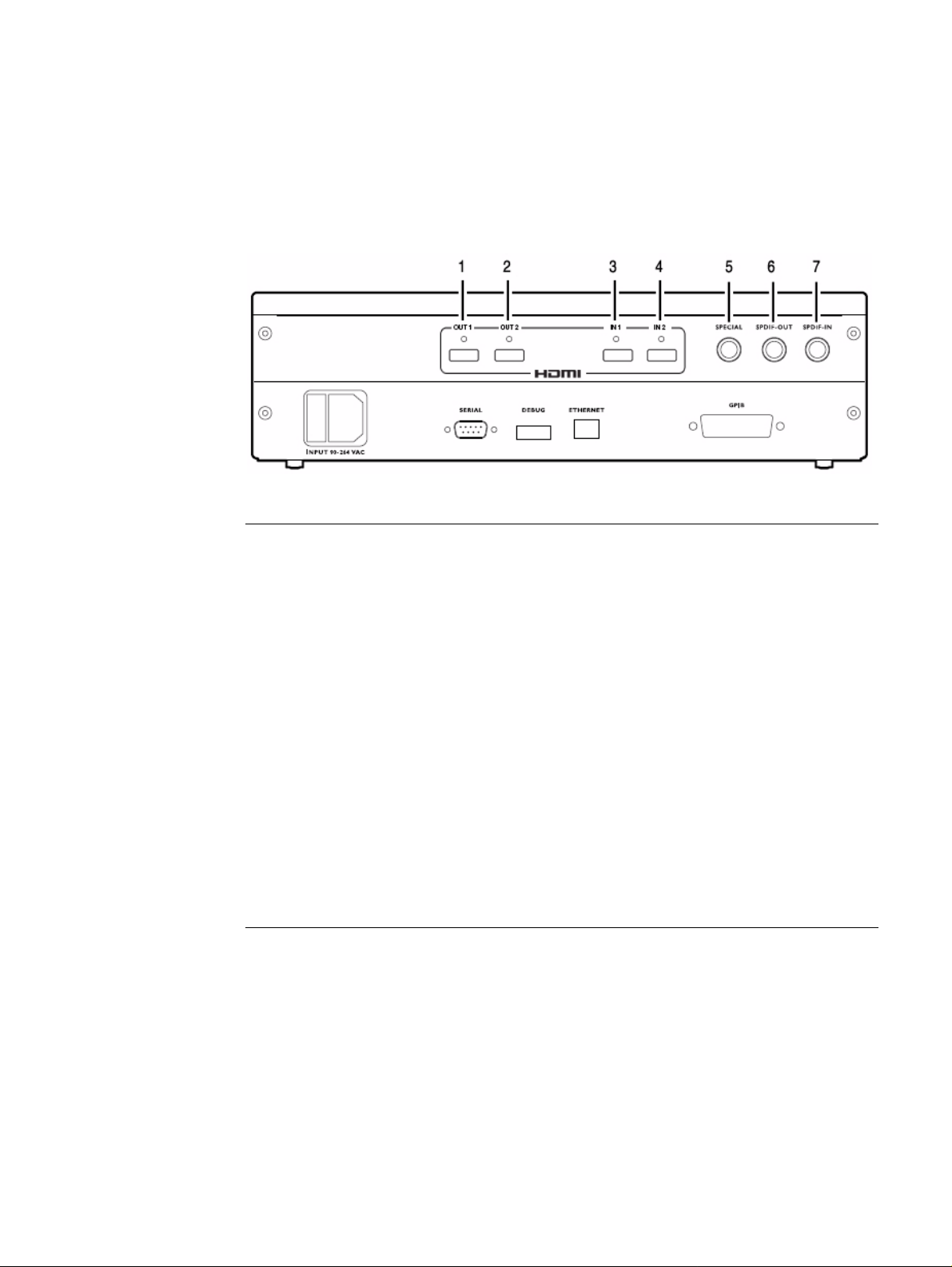
The video interfaces on the 882EA HDMI are shown below .
Interface Description
1 HDMI OUT 1 connector outputs full single link HDMI 1.3 video, as well as DVI and
modern HDMI-compatible digital video signals.
2 HDMI OUT 2 connector outputs full single link HDMI 1.3 video, as well as DVI and
modern HDMI-compatible digital video signals.
3 HDMI IN 1 connector accepts full single link HDMI 1.3 video, as well as DVI and
modern HDMI-compatible digital video signals.
4 HDMI IN 2 connector accepts full single link HDMI 1.3 video, as well as DVI and
modern HDMI-compatible digital video signals.
5 SPECIAL connector provides multiple outputs, including:
• digital composite sync
• line sync
• frame sync
• movable scope trigger (probe) pulse
• pixel clock signal
6 SPDIF OUT connector outputs audio to an external receiver.
7 SPDIF IN connector inputs audio from an external source.
HDMI interface
The HDMI interface emulates an HDMI-compliant video display. The HDMI connector
pinouts are shown in the following table.
882 Video Test Instrument User Guide (Rev A.35) 5
Page 18

HDMI Type A Connector Pinouts
Pin Signal Pin Signal Pin Signal
1 TMDS Data 2+ 7 TMDS Data0+ 13 CEC
2 TMDS Data2 Shield 8 TMDS Data0 Shield 14 Reserved (N.C.)
3 TMDS Data2- 9 TMDS Data0- 15 SCL
4 TMDS Data1+ 10 TMDS Clock+ 16 SDA
5 TMDS Data1 Shield 11 TMDS Clock Shield 17 DDC/SEC Ground
6 TMDS Data1- 12 TMDS Clock- 18 +5 V Power
19 Hot Plug Detect
Special Sync interface
Use the Special connector to output frame sync, line sync, composite sync, or a special
probe pulse. For more information, see Chapter 14, “Using Special Sync Output.”
6 Chapter 1 Getting Started
Page 19
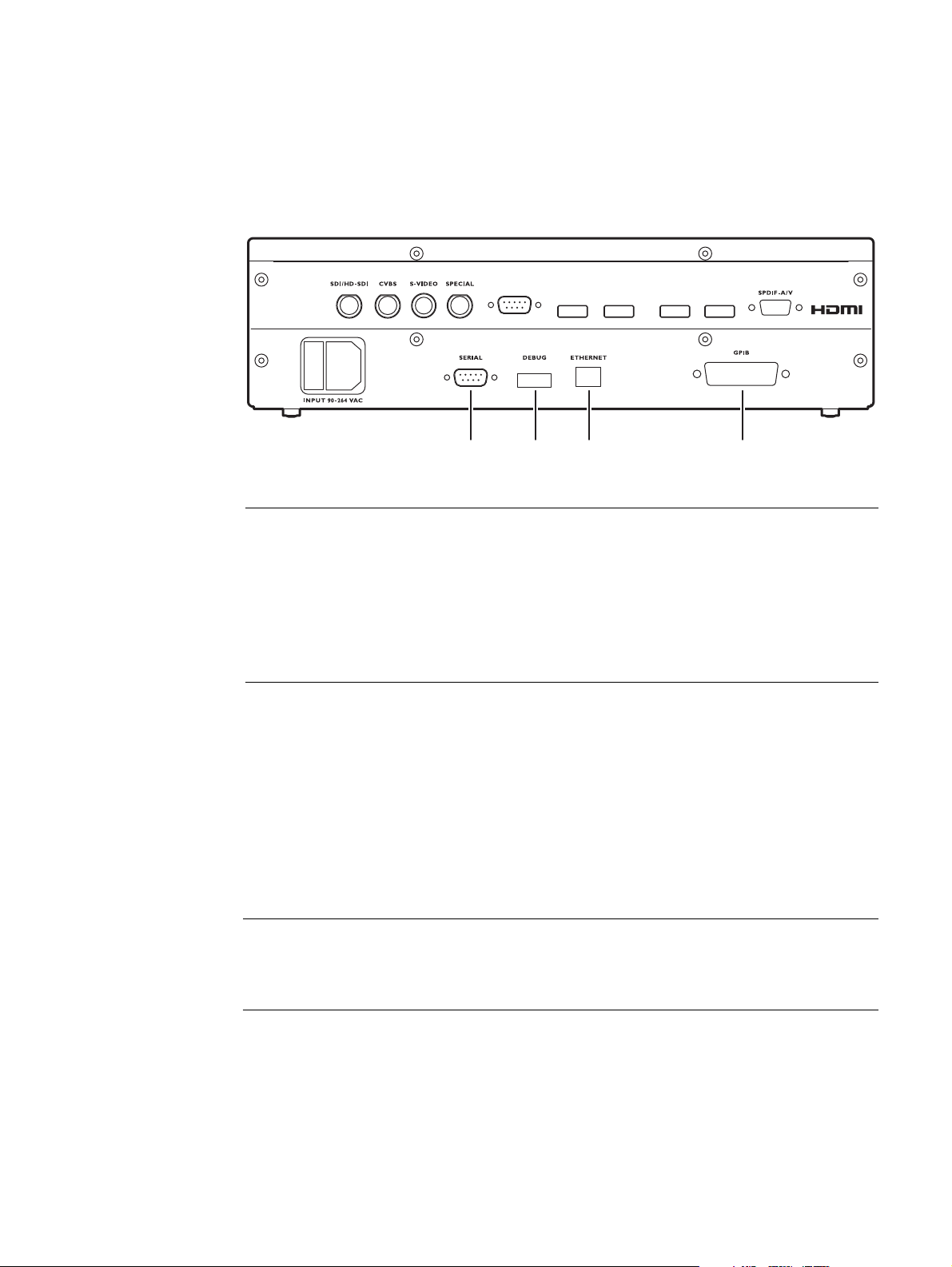
Computer interfaces
This section describes the 882’s computer interfaces. The computer interfaces are shown
below (882C shown).
Connector Description
1 SERIAL connector provides RS-232C serial data communication interface for the
882.
HDMI OUT 1
VGA
123 4
HDMI OUT 2 HDMI IN 1 HDMI IN 2
2 DEBUG connector is for Quantum Data use only.
3 ETHERNET connector is used to connect the 882 with a TCP/IP network, for
remote administration and control, and for sharing resources from a file server.
4 GPIB connector provides IEEE-488 GPIB interface to the generator (882 only; not
provided on 881 generators).
RS-232 interface
Each 882 has a standard RS-232 serial connector, labeled “SERIAL.” This is a 9-pin
D-Sub male connector which enables you to connect the 882 with a computer. A null
modem cable is provided to support this interface. You can communicate with the 882
through the command line interface using a termi nal emulator such as HyperTerminal. For
more information, see “Working with the serial interface” on page 30. The pinouts for the
RS-232 connector are shown in the following table.
Pin Signal Pin Signal Pin Signal
1 Data Carrier Detect 4 Data Terminal Ready 7 Request to Send
2 Received Data 5 Signal Ground 8 Clear to Send
3 Transmitted Data 6 Data Set Ready 9 Ring Indicator
882 Video Test Instrument User Guide (Rev A.35) 7
Page 20

GPIB interface
The GPIB interface allows you to use the 882 as a programmable vide o signal source in a
larger automated test system. The GPIB connector pinouts are listed in the following t able.
Pin Signal Pin Signal Pin Signal Pin Signal
1 DIO1 7 NRFD 13 DIO5 19 Shield
2 DIO2 8 NDAC 14 DIO6 20 Shield
3 DIO3 9 IFC 15 DIO7 21 Shield
4 DIO4 10 SRQ 16 DIO8 22 Shield
5 EOI 11 ATN 17 REN 23 Shield
6 DAV 12 Shield 18 Shield 24 Signal Ground
8 Chapter 1 Getting Started
Page 21
Front panel interface
Recent Folder
Folder
Tool !
Setting
Rejected
Selected
*
- Disabled
+
Enabled
Item Display
Menu Selection Keys
Soft Keys Status Indicators
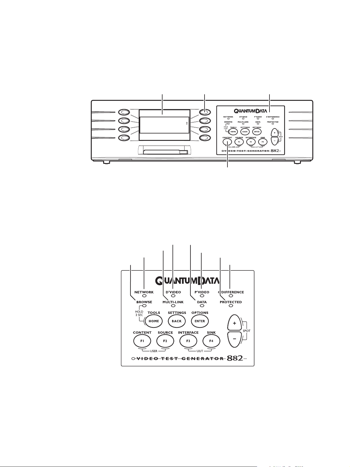
This section describes the front panel interface for operating the 882. The front pa nel keys
are shown below.
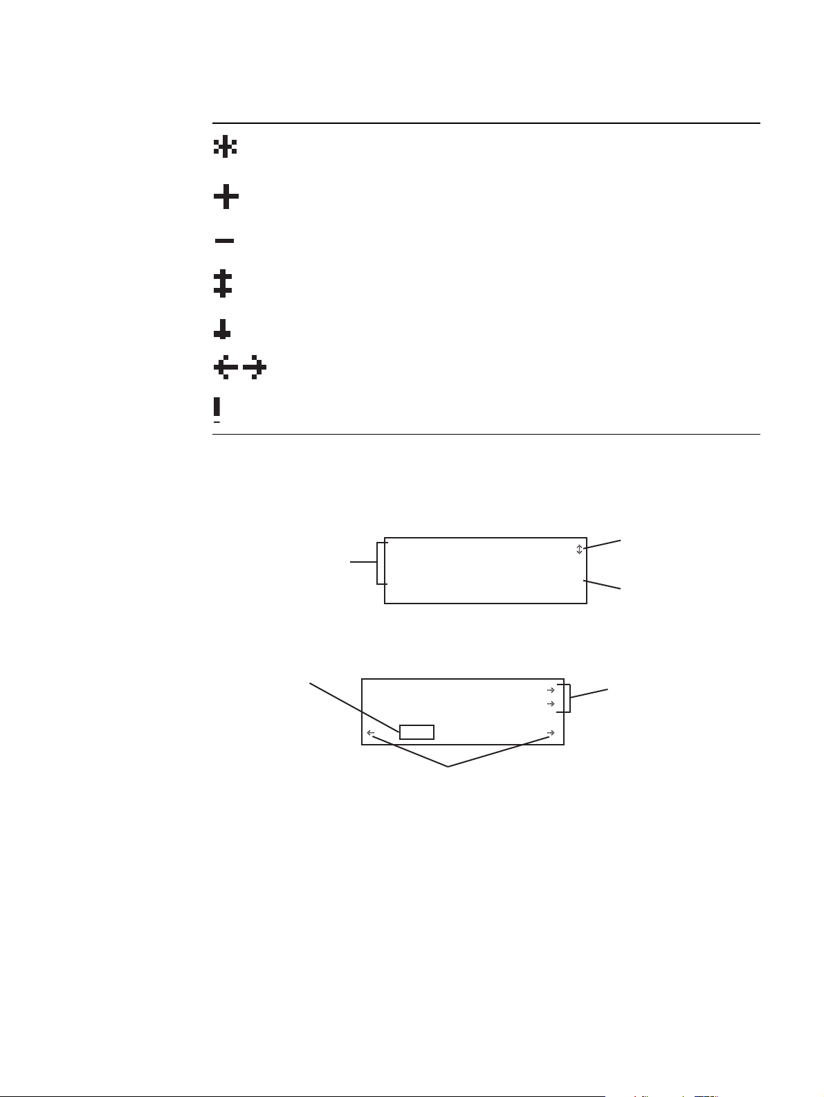
Status indicators
Status indicators provide feedback about the operational status of the 882. The graphic
below shows the location of the status indicators.
Digital video active
Multi-link video active
Ethernet connection active
Browse mode active
Output contains data (InfoFrames)
Packet video active
Output encrypted (HDCP)
Color difference video active
882 Video Test Instrument User Guide (Rev A.35) 9
Page 22
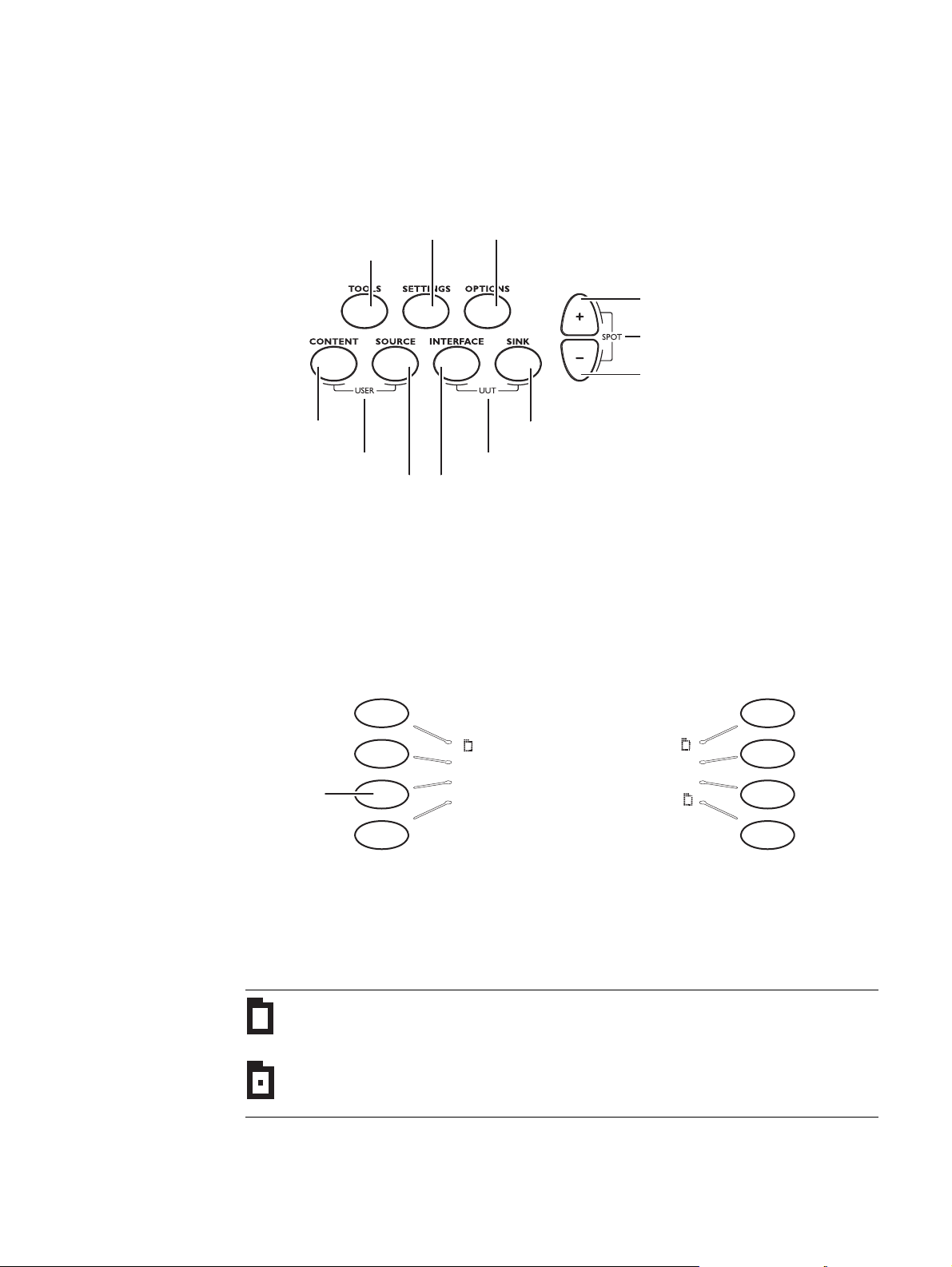
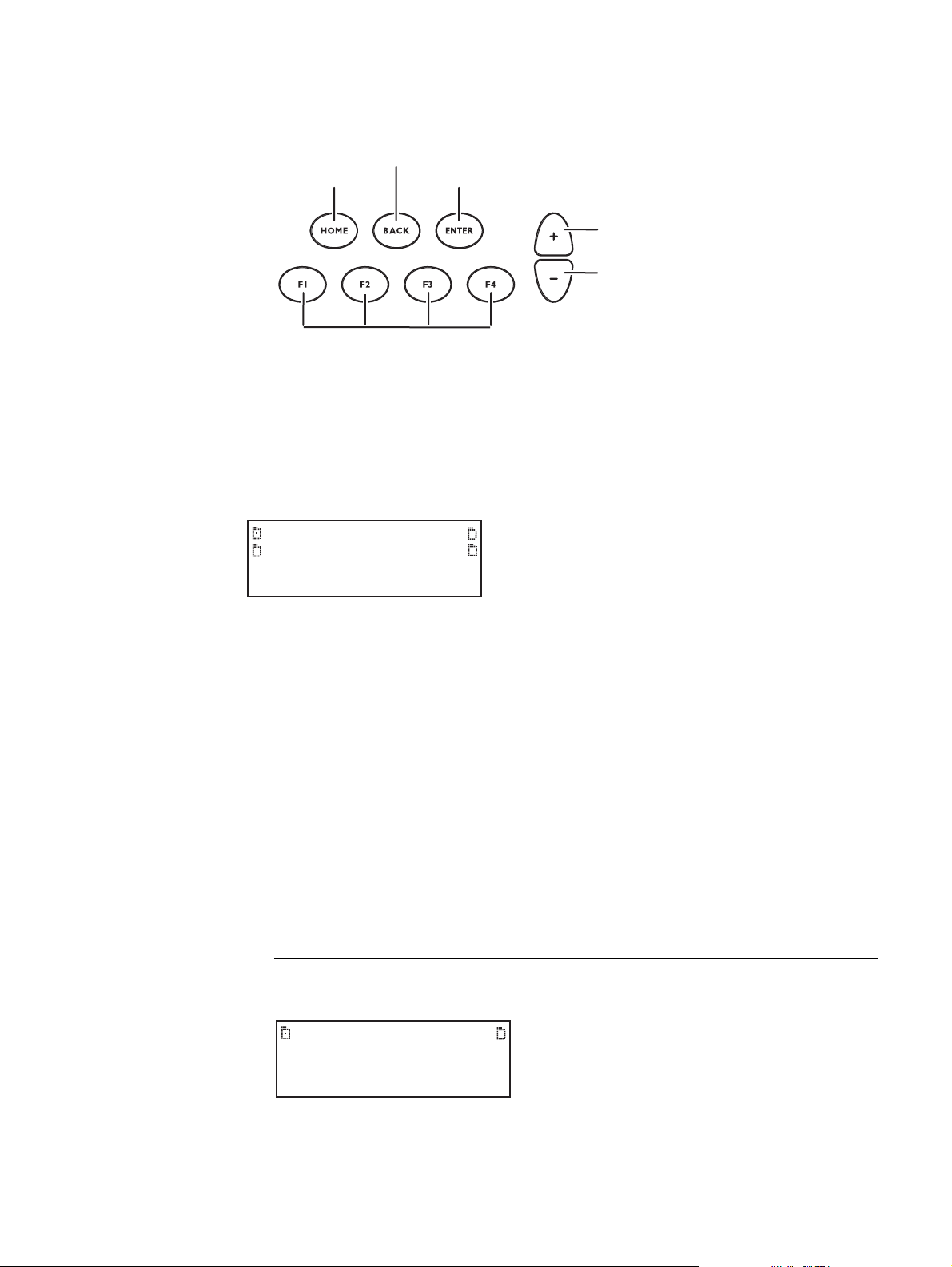
Menu selection keys
k
You can access the 882’s menus using the menu selection keys depicted below.
Set advanced parameters
Select tool
Select image
Select user profile
for current items
Select format
Select output
Set basic options
for current item
Page up,
increase value
Go to selected item
Page down,
decrease value
Displays information about UUT
Select device type
Selecting menu items
When you press a menu selection key, a menu appears on the 882’s display. Each menu
item corresponds to a key located adjacent to the item. These keys are called “soft keys”
because their functions change depending on the items that appear on the 882’s display.
For example, for the menu shown below, the soft key at the upper left corresponds to the
System item on the 882’s display.
System Reports
Sequence ImgShift
Press this
ey to select
Probe
Probe Analyzer
AFC CEC
Pressing a soft key either selects an item, enables or disables the item, or causes
additional information about the item to appear on the 882’s display. An icon located next
to an item provides additional information about the item. Following is a list of icons and
their meanings.
Icon Meaning
Folder containing related items.
Recently visited folder.
10 Chapter 1 Getting Started
Page 23
Icon Meaning
j
y
Image
Rendition
IVER
These represent
navigational direction
arrows to other settings
using adjacent item key
ISUB
0000 0
These represent navigating
direction arrows for moving
the flashing cursor to another
digit using adjacent item key
This is a command
setting that is set
one digit at a time
via flashing cursor
using spot keys
Indicates active item in list of mutually exclusive items.
Item is active, but may be deactivated by pressing soft key.
Item is not active, but may be activated by pressing soft key.
Value may be increased by pressing Up (+) key, or decreased by pressing
Down (-) key.
Page down to view more items.
Scroll left to previous option, or right to next option
Selecting this item will cause an action.
Item selection examples
The following examples show the different types of menu items.
These represent members
of a group where only one
item can be selected using
an adjacent item key
*
ACS
DCS
DSS
AFD:1
PR:5
Pedestal
+
This represents a
setting that is changed
using the spot keys
This represents an
option that is enabled (+)
or disabled (-) using the
acent item ke
ad
882 Video Test Instrument User Guide (Rev A.35) 11
About the Settings and Options keys
The Options key enables you to view or set basic options for the selected item. For items
with multiple pages of options, press the Options key again to view additional pages.
Typically, options are attributes that are either enabled or disabled. For example, the
screen below shows the options for a format. On this screen, the asterisk (*) next to DSS
Page 24

means that DSS is selected, the + sign next to SyncOnG means that this option is
ACS SyncOnR DCS SyncOnG+
*DSS SyncOnB-
-Pedestal
enabled, and the - signs next to Pedestal, SyncOnR, and SyncOnB mean that these
options are disabled. If you press the soft key adjacent to SyncOnR, the - will change to a
+, indicating the option is now enabled.
The Settings key enables you to view or set a parameter to a value. For example, the
screen below shows the settings for the video signal of a format. To change the value of
the XVSI, AVSI, or DVSI setting, press the sof t keys next to the arrows on the bottom row
of the 882’s display until the blinking cur sor is on the value you want to cha nge. Increment
the value up or down by pressing the + and - keys.
Video Signal ->
Interface ->
XVSI AVSI DVSI
<- 1 3 0 ->
To see other settings for the format, press the soft key adjacent to the arrows. If you press
the soft key next to the arrow by Video Signal, you will see the settings for Video T iming. If
you press the soft key next to the arrow by Interface, you will see the settings for
Synchronization.
12 Chapter 1 Getting Started
Page 25

882 file system and media
The 882 has a file system comprised of a System folder and a Library folder of resource
files that can be stored on multiple media (storage devices or locations). The files in the
file system are briefly described below.
882 file system
The 882 generator file system is comprised of two main directories (folders): 1) System
and 2) Library . Th e System folder contains the realtime operating system and firmwa re file
(vxWorks) and the gateware. The Library folder contains the following resource files:
• Fonts - Object files used to define the font types.
• Formats - XML files defining the format p arameter settings.
• FormatLib - XML files for configuring the source list of formats.
882 media
• Images - C++ object files, executables, bitmaps, and XML files for rendering images.
• ImageLib - XML files for configuring the content list of images.
• Sequences - XML files with instructions for test sequences.
• Users - XML files for user configuration profiles.
The 882 provides for two read/write local storage media and one server-based mediu m
(storage locations):
• Flash memory.
•PCM CIA card.
• Host server.
Each of these storage locations contains or can contain all the 882’s System and Library
files.
882 Video Test Instrument User Guide (Rev A.35) 13
Page 26

882 operational modes
The 882 has two operational modes: 1) Basic mode and 2) Browse mode. The 882 boots
up in the Basic mode which is the main operating mode you will be using. Both modes are
described below along with instructions for booting up the 882.
Booting up the 882
When the 882 is powered up it presents a screen enabling you to select the boot device.
The 882 loads its operating system and firmware from a from the selected boot device or
specified medium (storage location). If you do not press a key within 5 seconds the
currently specified boot location is used and boot up proceeds. This feature enables you
to control where the 882 boots from in instances where the default lo cation is either
inaccessible or known to have a suspect application file. Follow the procedure below to
boot the 882:
To boot the 882:
1. Apply power to the 882. The following display appears.
If you are sure you want to boot from the current storage location you can let the system
boot automatically.
Quantum Data
Windriver
vxWorks System Boot
Press any key for setup
a. T o boot from an alternative device, pr ess any key within five seconds. The following
screen appears on the 882’s display:
!BootDev !Passwd
!HostName !Flags
!FileName !Other
!InetAddr !TrgtName
2. Choose the !BootDev item by pressing the adjacent soft key. The following menu
appears:
3. Do one of the following:
• To boot from the file server, press the soft key adjacent to Network Boot.
• To boot from the 882’s flash memory , press the soft key adjacent to Internal Flash.
14 Chapter 1 Getting Started
Page 27

• To boot from the 882’s PC card, press the soft key adjacent to PCMCIA Boot.
4. Press the Options (Enter) key to save the configuration.
5. Either restart the 882 by cycling the power or press the Tools key to return to the boot
menu.
6. Scroll down to allow viewing and selection of the BootNow item as shown below.
!FileName !Other
!InetAddr !TrgtName
!HostAddr BootNow
!User
7. Select BootNow by pressing the adjacent item selection key. The following display
appears:
Press UP arrow
to Boot Now
Basic mode
Browse mode
8. Press the + key to boot the 882.
The Basic mode is the main operating mode of the 882. Typically, you will use the Basic
mode when testing displays and sources. In Basic mode you can select formats and
images, create and run test sequences, view and edit object properties, and so on.
In the Basic mode you make selections in the front panel with the item selection keys and
the soft keys. The function of the menu selections key is described a nd depicted in “Menu
selection keys” on page 10.
Browse mode is for advanced users who want to load objects from different media and
program the 882 function keys. This mode is for expert users only.
882 Video Test Instrument User Guide (Rev A.35) 15
Page 28
When in Browse mode, the selection keys shown below are active.
Go to root folder
To previous folder
Jump to preset location
Open selected folder
Page up
Page down
The procedure below describes how to place the 882 in Browse mode:
To place the 882 in Browse mode:
Press and hold the Tools key. The message Hold to enter Browse Mode appears on the
882’s display. Continue holding the Tools key until the Browser status indicator lights. The
following menu appears:
Flashmem
NetPlace
PCCard
Cache
Browsing other media
In Browse mode, you can view and use objects located in the 882’s flash memory, a
network file server, the 882’s PC card, or the 882’s cache memory.
To choose the medium to browse:
1. Press the soft key adjacent to the medium you want to browse.
Medium Description
Flashmem Non-volatile memory in 882.
NetPlace File server connected with 882.
PCCard Compact Flash card in 882.
Cache Volatile memory in 882. This source contains objects that have been
used (loaded into cache) since the 882 was started.
A list of folders on that medium appears on the 882’s display as shown below.
16 Chapter 1 Getting Started
System Library
Page 29

2. Choose the folder you want to open by pressing the ad jacent sof t key. The contents of
Fonts FormatLib
Formats Images
Sequence UserData
Users WebFiles
the folder appears on the 882’s display. If you need to return to the previous menu list
press the back (settings) key.
3. Continue selecting folders to open until you locate the item you need. To use an item,
press the adjacent soft key.
Setting the 882’s path
The 882 can be set to access format, image, and sequence files stored on its flash
memory , PC card, o r on a file server. T o do this, you must set th e 882’ s path to point to the
corresponding folders on the desired medium. You can set the path using the command
line interface or the front panel.
To set the 882’s path using the front panel:
1. Place the 882 in Browse mode by holding down the Tools key until the media menu
appears on the 882’s display as shown below.
Flashmem
NetPlace
PCCard
Cache
2. Choose the desired medium by pressing the adjacent soft key. The folders on the
selected medium (for example flash memory) appear on the 882’s display as shown
below.
System Library
3. Press the soft key adjacent to the Library folder. The contents of the selected folder
appears on the 882’s display as shown in the example below.
Fonts FormatLib
Formats Images
Sequence UserData
Users WebFiles
882 Video Test Instrument User Guide (Rev A.35) 17
4. Press the soft key adjacent to the folder you want to use. For example, to set the format
path, press the soft key adjacent to Formats. The contents of the Formats folder
appears on the 882’s display.
Page 30

5. Select a format by pressing the adjacent soft key. The format path is now set to the
selected folder on the selected medium.
To set the 882’s path using the command line interface:
1. Establish a session with the 882 using either HyperT erminal over a serial connection or
Telnet over an Ethernet LAN. See “Establishing a terminal session with the 882” on
page 30 or “Establishing a Telnet session with the 882” on page 33.
2. For each file type (format, image, and sequence), set the pa th parameter to the
corresponding folder on the desired me d ium . In th e co mm a nd sy ntax, spec ify th e
medium as follows:
• Flash memory: tffs0 (TFFS - Transaction Flash File System)
• PC card: card0
Note: Please note that you must us a PCMCIA card that is formatted in FAT16
filesystem. If you use an card that is formatted in FAT32, the 882 will not boot.
• File server: <server name>
3. For each file type (format, image, and sequence), set the path parameter to the
corresponding folder on local 882 media using the following commands:
FMTP /medium/Library/Formats
IMGP /medium/Library/Images
SEQP /medium/Library/Sequences
For example the medium name for the PC card is /card0. So you would enter the
following command to set the image path to the image directory on the PC card:
IMGP /card0/Library/Images
The 882 will now display the images on the PC card when you press the Contents key.
The medium name for the flash memory is /tffs0. So you would enter the following
command to set the image path to the format directory on the flash memory:
FMTP /tffs0/Library/Formats
The 882 will now display the formats on the flash memory when you press the Source
key.
The medium name for the network is the server (host name) memory. So you would
enter the following command to set the image path to the format di rectory on the flash
memory:
SEQP /Server030/Library/Sequences
The 882 will now display the sequences on the server when you press the Tools key
and then select sequences.
18 Chapter 1 Getting Started
Page 31

Programming the 882’s function keys
System
Sequence
Probe
AFC
Analyzer
Reports
ImgShift
CEC
The 882 is equipped with four function keys (F1 through F4) that can be programmed as
shortcuts to folders. The procedure below describes how to program the function keys.
To program a function key as a folder shortcut:
1. Browse to the folder to which you want to create a shortcut.
2. Hold down a function key (F1, F2, F3, or F4) to assign the key to the folder.
Switching from Browse mode to Basic mode
To switch from Browse mode to Basic mode:
Press and hold the Tools key. The message Hold to enter Basic Mode appears on the
882’s display. Continue holding the Tools key until the Browse Mode status indicator turns
off and the Tools menu appears.
882 Video Test Instrument User Guide (Rev A.35) 19
Page 32

Web interface
The 882 has a built-in Web server that enab les you to interact with the 882 using a PC an d
an Ethernet connection. The Web interface includes the following functions:
• Format Editor for creating formats and modifying and viewing fo rmat parameters. For
more information about the Format Editor , see “Creating a new format using the Format
Editor” on page 193.
• Virtual Front Panel for operating the 882 remotely.
• CMD Terminal for operating the 882 using the command line interface.
• 882 FTP Browser for copying files between media within the 882, between 882s, and
between a 882 and a PC.
• Calibration reports (Currently not available)
This section describes how to operate the Virtual Front Pan el, CMD Terminal, and the 882
FTP Browser.
Working with the Virtual Front Panel
The Virtual Front Panel enables you to perform remotely the same tasks as you would
with the 882’s front panel. To use the Virtual Front Panel, you must have a PC connected
to a 882 either through an Ethernet LAN or locally through an Ethernet crossover cable
connected between the Ethernet ports on the 882 and the PC. These configurations are
described in more detail in “Establishing a network environment” on page 130. You must
also have the Java Runtime Environment (JRE) 1.5 or later installed on your PC. You can
download the JRE from http://www.java.com/en/download/windows_ie.jsp.
To use the Virtual Front Panel, you must know the IP address of the 882. The following
procedures describe how to determine the 882’s IP ad dress and how to access the V irtual
Front Panel using a Web browser.
To determine the IP address of the 882:
1. Press the Tools key. The Tools menu appears on the 882’s display as shown below.
System
Sequence
Probe
AFC
Reports
ImgShift
Analyzer
CEC
20 Chapter 1 Getting Started
Page 33

2. Choose the System item by pressing the adjacent soft key. The System menu appears
on the 882’s display as shown below.
Clock Clone*
CalFactor Server
Network About
Serial GPib
3. Choose the Network item by pressing the adjacent soft key. The 882’s IP address
appears on the 882’s display as shown below.
IP Address
192.168.254.1
Subnet Mask
255.255.255.000
To use the Virtual Front Panel:
1. Open a Web browser (such as Internet Exp lor er) a nd type th e 8 82’s IP address in the
address entry field. For example, ente r the following: http://192.168.254.1.
The 882 home page appears in the browser.
882 Video Test Instrument User Guide (Rev A.35) 21
Page 34

Note: You can add the p age to your list of favorite pages in your W eb browser to avoid
retyping the IP address each time you want to access the page.
2. Click the Virtual Front Panel link. The Virtual Front Panel appears.
3. Use your mouse to click the virtual keys, which function the same as if you pressed the
physical keys on the 882.
Working with the CMD (Command) Terminal
The CMD Terminal allows you to send commands to the 882 using the command line
interface.
To use the CMD Terminal:
1. Access the Virtual Front Panel page. See “To use the Virtual Front Panel:” on p age 21.
2. Click the CMD Terminal link. The CMD Terminal window appears.
22 Chapter 1 Getting Started
Page 35

3. In the box at the top of the CMD Terminal window, enter a command, and then press
Enter. The command appears in the lower pane.
Working with the 882 FTP Browser
If you create objects on a PC, such as images or formats, you can use the 882 FTP
Browser to copy these objects to a 882. You can also use the 882 FTP Browser to copy
objects between media in a 882 and to copy objects from one 882 to another.
Copying files from a PC to a 882
To copy files from a PC to a 882:
1. Access the 882’s FTP browser by choosin g the FTP Browser menu item from the main
web page. The 882 FTP Browser appears. The Instrument Files area
882 Video Test Instrument User Guide (Rev A.35) 23
Page 36

2. shows the files stored on the 882. The Host Files area shows the files stored on the PC.
3. In the Host Files area, locate and select the file or folder you want to copy.
4. In the Instrument Files area, locate the destination folder for the file as follows:
a. In the Look in box, click the down arrow and select the medium where you want to
b. In the list of files, open the destination folder.
5. In the Host Files area, click Download. The Transfer Files dialog box appears.
6. Verify that the source file or folder and the destination folder are correct, and then click
OK.
7. The Copying Files dialog box appear s showing the st atus of the opera tion. When the
status is 100%, click Done.
24 Chapter 1 Getting Started
copy the file. Select tffs0 for the 882’s flash memory or card0 for the 882’s PC card.
Page 37

Copying files from a 882 to a PC
To co p y fil es from a 88 2 to a PC :
1. Access the 882’s FTP browser by choosin g the FTP Browser menu item from the main
web page. The 882 FTP Browser appears. The Instrument Files area shows the files
stored on the 882. The Host Files area shows the files stored on the PC.
2. In the Instrument Files area, locate and select the file or folder you want to copy as
follows.
a. In the Look in box, click the down arrow and select the medium where the file is
located. Select tffs0 for the 882’s flash memory or card0 for the 882’s PC card.
b. In the list of files, select the file or folder you want to copy.
3. In the Host Files area, open the destination folder where you want to copy the files.
4. In the Instrument Files area, click Upload. The Transfer Files dialog box appears.
882 Video Test Instrument User Guide (Rev A.35) 25
Page 38

5. Verify that the source file or folder and the destination folder are correct, and then click
OK.
6. The Copying Files dialog box appear s showing the st atus of the opera tion. When the
status is 100%, click Done.
Copying files between the 882’s flash memory and PC card
To copy files between media in a 882:
1. Access the 882’s FTP browser by choosin g the FTP Browser menu item from the main
web page. The 882 FTP Browser appears. The Instrument Files area shows the files
stored on the 882. The Host Files area shows the files stored on the PC.
2. In the Instrument Files area, click the down arrow by the Look in box and select tffs0.
This is the 882’s flash memory.
3. Repeat step 2 to open a second 882 FTP Browser . In the Instr ument Files area of the
second 882 FTP Browser window , click the down arrow by the Look in box and select
card0. This is the 882’s PC card.
26 Chapter 1 Getting Started
Page 39

Note: Please note that you must us a PCMCIA card that is formatted in FAT16
filesystem. If you use an card that is formatted in FAT32, the 882 will not boot.
4. Locate the file or folder you want to copy in the source window.
5. Locate and open the destination folder in the destination window.
6. Drag the file or folder from the Instrument Files area of the source window to the
Instrument Files area of the destination window.
Copying files between 882s
To copy files between 882s:
1. Open a Web browser (such as Internet Explorer) and type the source 882’ s IP address
in the address entry field. The source 882’s home page appears in the browser.
882 Video Test Instrument User Guide (Rev A.35) 27
Page 40

2. Access the 882’s FTP browser by choosin g the FTP Browser menu item from the main
web page. The 882 FTP Browser appears. The Instrument Files area shows the files
stored on the 882. The Host Files area shows the files stored on the PC.
3. Repeat steps 1 and 2 for the target 882.
Note: You now have two instances of the 882 FTP Browser running: one for the source
882 and one for the target 882.
4. In the 882 FTP Browser window for the source 882, locate the file or folder you want to
copy as follows:
a. In the Look in box, click the down arrow and select the medium where the file or
Note: Please note that you must us a PCMCIA card that is formatted in FAT16
filesystem. If you use an card that is formatted in FAT32, the 882 will not boot.
b. In the list of files, select the file or folder.
28 Chapter 1 Getting Started
folder is located. Select tffs0 for the 882’s flash memory or card0 for the 882’ s PC
card.
Page 41

5. In the 882 FTP Browser window for the target 882, open the destination folder as
follows:
a. In the Look in box, click the down arrow and select the medium to which you want
to copy the file or folder. Select tffs0 for the 882’s flash memory or card0 for the
882’s PC card.
b. In the list of files, open the destination folder.
6. Drag the file or folder from the Instrument Files area to the Host Files area of the source
window. A confirmation dialo g box appears.
7. Click OK to copy the files.
8. Locate the file or folder in the Host Files area in the target window . Drag the file or folder
from the Host Files area to the destination folder in the Instrument Files area of the
target window. A confirmation dialog box appears.
9. Click OK to copy the files.
882 Video Test Instrument User Guide (Rev A.35) 29
Page 42

Command line interface
Common test procedures can be accomplished using the 882’s physical controls on the
front panel, Virtual Front Panel or through the comman d line interface. The 882 supports
an ASCII command and query language that allows you to control the 882 interactively or
through batch processing of command files. All 882 functions are supported through this
interface. The command line interface is available through three physical interfaces:
• Serial (RS-232) interface (terminal session, such as HyperT erminal, via the serial port)
• Ethernet network interface (Telnet session or Web browser via the Ethernet port)
• GPIB (IEEE-488) interface (via the GPIB port)
The serial and Ethernet interfaces are described in this section. For information on the
GPIB interface, see Chapter 6, “Using GPIB Interface.”
Working with the serial interface
This section describes how to connect the 882 to the PC via the serial port, how to
establish a terminal session with the 882 using a terminal emulator such as
HyperTerminal, and how to change serial port settings.
To connect the 882 to the PC:
To set up the 882 to use the serial interface, connect a serial null modem cable from the
serial port of the PC to the SERIAL connector on the rear of the 882.
Establishing a terminal session with the 882
The following procedure describes how to establish a terminal session with the 882
through the serial port. For information about establishing a Telnet session over an
Ethernet LAN, see “Establishing a Telnet session with the 882” on page 33.
To establish a terminal session with the 882:
1. Open a terminal emulator, such as HyperTerminal. Configure the terminal emulator to
use the parameters set in the 882. By default, the 88 2’s serial p ort is set to 9600 baud,
8 data bits, no parity, 1 stop bit, no flow control.
2. Establish a terminal connection with the 882. Press Enter un til the C:> prompt appears.
Configuring the 882’s serial port
The following procedures describe how to change the 882’s default serial port
configuration for a terminal session. You can configure the serial port through either the
front panel, Virtual Front Panel or through the command line interface.
30 Chapter 1 Getting Started
Page 43

To configure the 882’s serial port through the front panel or Virtual
Serial Port
9600 baud
8 N 1
Front Panel:
1. Press the Tools key. The Tools menu appears on the 882’s display as shown below.
System
Sequence
Probe
AFC
Reports
ImgShift
Analyzer
CEC
2. Choose the System item by pressing the adjacent soft key. The System menu appears
on the 882’s display as shown below.
Clock Clone*
CalFactor Server
Network About
Serial GPib
3. Choose the Serial item by pressing the adjacent soft key. The serial port settings
appear on the 882’s display.
Selec
4. Press the Settings key. The following information appears on the 882’s disp lay:
Serial Port
Set Params
BAUD FLOW ->
9600 N ->
5. To change the baud rate, do the following:
a. Position the blinking cursor on the baud rate setting. To do this, press the soft key
adjacent to the arrow by the baud rate setting to move the cursor left or right until
it appears on the baud rate setting.
b. Press the + or - keys to adjust the baud rate setting up or down.
6. To change the flow control state, do the following:
a. Position the blinking cursor on the flow control setting. To do this, press the soft
keys adjacent to the arrow by the flow control setting until the cursor appears on
the current flow control setting (N, H, or T).
b. Press the + or - keys to change the setting.
882 Video Test Instrument User Guide (Rev A.35) 31
Page 44

7. To change the number of data bits, do the following:
Serial Port
Set Params
<- CHAR PRTY STOP
8 N 1 ->
a. Press the soft keys adjacent to the third row until CHAR appears. The current d ata
bits setting is shown in the bottom row.
b. Position the blinking cursor on the CHAR setting. To do this, press the soft keys
adjacent to the arrow by the CHAR setting until the cursor appears on the current
data bits setting.
c. Press the + or - keys to adjust the setting up or down.
8. To change the parity, do the following:
a. Position the blinking cursor on the PRTY setting. To do this, press the soft keys
adjacent to the arrow by the PRTY setting until the cursor appears on the current
parity setting.
b. Press the + or - keys to adjust the setting up or down.
9. To change the stop bits, do the following:
a. Position the blinking cursor on the STOP setting. To do this, press the soft keys
adjacent to the arrow by the STOP setting until the cursor appears on the current
stop bits setting.
b. Press the + or - keys to adjust the setting up or down.
10. To save the changes, press the Enter (Options) key. The following choice s appear on
the 882’s display:
Apply Settings?
Back
Yes No
To save the changes, choose the Yes item by pressing the adjacent soft key.
To exit without saving the changes, choose the No item.
To return to the previous screen without saving the changes, choose the Back item.
To configure the 882’s serial port through the command line interface:
1. Establish a session with the 882 using HyperT erminal over a serial connection or T elnet
over an Ethernet LAN. For instructions, see “Establishing a terminal session with the
882” on page 30 and “Establishing a Telnet session with the 882” on page 33.
32 Chapter 1 Getting Started
2. At the session prompt, enter the following command to query the 882 for the curre nt
serial port settings:
Page 45

MODE?
The 882 returns the current values:
9600,N,8,1,N,N
3. To change the settings, enter the following command:
MODE baud parity data stop handshake protocol
For example, to change the baud rate to 38400, enter the following command:
MODE 38400 n 8 1 n n
Note: In this example, after you press Enter, the baud rate of the session and baud
rate of the 882 will no longer match. This will cause the session to lose its connection
with the 882. Close the session, change the session baud rate to 38400, and then
re-open the session.
Working with the network interface
This section describes how to connect the 882 to a PC via an Ethernet LAN and how to
establish a Telnet session with the 882.
To connect the 882 to a PC over an Ethernet LAN:
1. Connect the Ethernet cable between the PC’s Ethernet port and an active Ethernet
jack.
2. Connect an Ethernet cable between the 882’s ETHERNET p ort and an active Ethernet
jack.
Establishing a Telnet session with the 882
The following procedure describes how to establish a Telnet session with the 882 over an
Ethernet LAN. For information about establishing a terminal session over a serial
connection, see “Establishing a terminal session with the 882” on p age 30.
To establish a Telnet session with the 882:
1. Using a text terminal application, such as DOS Command Prompt, enter the following
command:
telnet 882IPaddress
Example:
telnet 192.168.254.220
2. The
882 Video Test Instrument User Guide (Rev A.35) 33
/tffs0>
Enter after each command.
prompt appears. Type commands at the
/tffs0>
prompt, and press
Page 46

Sending commands interactively
This section describes how to send commands through an interactive command line
interface session. The 882 parses command lines one at a time. Command lines must be
terminated with a carriage return (<cr>). The 882 immediately echoes each character as it
is received and places it in a command line buffer. Commands are not case sensitive.
When sending multiple commands at once, separate each command with a semi-colon.
For example, to load the 480p59 format with the SMTPEbar image, send the following
commands:
FMTL 480p59
IMGL SMPTEbar
ALLU
Common commands
• To apply an image and format to the 882 hardware, enter:
ALLU
• To display the name of the form at currently in the format buffer, enter:
FMTL?
• To load a format, enter:
FMTL format_name
• To apply the format to the 882 hardware, enter:
FMTU
• To load an image, enter:
IMGL image_name
• To apply the image to the 882 hardware, enter:
IMGU
Sending command files (serial interface only)
When developing more complex, custom test sequences or formats, it is easiest to enter
commands in a text file, and then send the file to the 882. This approach allows you to
modify the file without entering the entire command script.
Note: Sending command text files can be performed via the serial interface only.
To send a text file to the 882:
1. Using a text editor, enter comman ds into a text file, and save the text file using a *.txt
extension.
34 Chapter 1 Getting Started
Page 47

2. Establish a session with the 882 u sing a terminal emulator , such as HyperTerminal over
a serial connection.
3. At the C:> prompt, transfer the text file to the 882. For example, to transfer a file using
HyperTerminal, do the following:
a. On the Transfer menu, click Send Text File. The Send Text File dialog box
appears.
b. Select the text file you want to send, and then click Open. HyperTerminal displays
the commands as they are sent.
c. Press Enter once to ensure that the last command is sent.
882 Video Test Instrument User Guide (Rev A.35) 35
Page 48

Working with user profiles
The 882 provides user profiles that enable you to quickly load pre-defined configurations.
This can be done either through the front panel, virtual front panel or the command line.
For example, you can create different profiles for each operator, production line, display
type under test, and so on.
A user profile is always active on the 882 (“User1” is the default profile). While active, the
882 tracks subsequent format and format options, format catalogs, interface, and content
selections made by the user. These configuration settings are saved to the active profile
when a different user profile is chosen on the 882.
To choose a user profile:
1. Press the Source and Content keys simultaneously (or press USER on the Virtual
Front Panel) to access the list of user profiles.
The following is an example of a set of user profiles that might appear on the 882’s
display. Note that User1 is active, which is indicated by the = sign.
=User1 User2
User3 User4
User5 User6
User7 User8
wr
2. Choose another user by pressing the adjacent soft key. For example, to change to
User5, press the soft key adjacent to User5. This will save the configuration settings for
User1 and select the profile for User5. Any subsequent configuration changes will
apply to User5.
Alternatively, to switch users using the command line interface, enter the following
command:
USRU username.xml
For example, to select User5, enter
USRU User5.xml
To query the current user, enter
USRU?
The 882 returns the current user name.
/tffs0/Library/Users/User5.xml
To create a new user profile:
The procedure for setting up a new user profile is accomplished using th e command line
interface.
36 Chapter 1 Getting Started
Page 49

1. Establish a session with the 882 using either HyperT erminal over a serial connection or
Telnet over an Ethernet LAN. See “Establishing a terminal session with the 882” on
page 30 or “Establishing a Telnet session with the 882” on page 33.
2. Enter the following command:
USRA username.xml
USRU username.xml
Note: A user name is 8 alphanumeric characters.
For example, to set up a user profile called “User3,” enter:
USRA User3.xml
USRU User3.xml
A new user profile is created with default configuration settings and becomes the active
profile on the 882. While active, the 882 tracks subsequent format and format options,
format catalogs, interface, and content selections made by the user. These configuration
settings are saved to the active profile when a different user profile is chosen on the 882.
To delete a user profile:
1. Enter the following command:
USRK username.xml
For example to delete User5, enter:
USRK User5.xml
882 Video Test Instrument User Guide (Rev A.35) 37
Page 50

38 Chapter 1 Getting Started
Page 51

2 Testing Video Displays
Topics in this chapter:
• General video display testing procedures
• Testing digital computer (IT) FPDs
• Testing digital component video HDTV (CE) FPDs
• Using the Image Caching feature
• Using the AuxTest image
• Using the ImageShift utility
• Adjust Frequency Function
• Keypad Utility
882 Video Test Instrument User Guide (Rev A.35) 39
Page 52

General video display testing procedures
This section provides an overview of basic steps performed to test your video display
using your 882 or 881. Testin g yo ur video display involves four basic steps:
1. Connecting 882 to display under test.
2. Selecting interface type for display under test.
3. Selecting a video format appropriate for display under test.
4. Selecting an image suitable for testing the display under test.
Making physical connection
The first step is to make a physical cable connection between the 882 and display under
test. The following table provides guidelines for connecting th e 882C, 882E, 881C or 882E
generator to the display under test.
Display type Signal type Port (Interface) Cable
Information
Technology
(IT)
Computer - VESA
(DMT, CVT)
Computer - VESA
DDWG
Analog component
RGB
Digital component
RGB
VGA VGA to VGA
HDMI OUT
(HDMI-D)
HDMI to DVI
DisplayPort
(882E only)
Consumer
Equipment
(CE)
Professional AVSDI
1. Optional cable available from Quantum Data.
SDTV - ITU-470-6
baseband
SDTV - ITU-470-6
baseband
SDTV - CEA-861B Analog component
HDTV CEA-861C
HDTV CEA-861C
(SMPTE-259M)
and HD-SDI
(SMPTE-292M-C)
Digital component
RGB
Analog composite
CVBS
Analog composite
S-Video
YPbPr
Digital component DVI
RGB
Digital component
HDMI RGB and YCbCr
Digital component
YCbCr
DisplayPort OUT DisplayPort
CVBS BNC to RCA
75 Ohm
SVIDEO S-Video
(miniDin)
VGA VGA to RCA
HDMI OUT
(HDMI-D)
HDMI OUT
(HDMI-H)
SDI/HD-SDI BNC Coax
HDMI to DVI
HDMI to HDMI
1
40 Chapter 2 Testing Video Displays
Page 53

Use the following table to connect the 882D or 881D generator to the display under test.
Display type Signal type Port (Interface) Cable
Information
Technology
(IT)
Consumer
Equipment
(CE)
Computer - VESA
(DMT, CVT)
Computer - VESA
DDWG
SDTV - ITU-470-6
baseband
SDTV - ITU-470-6
baseband
SDTV - CEA-861B Analog component
HDTV CEA-861C
HDTV CEA-861C
Analog component
RGB
Digital component
RGB
Analog composite
CVBS
Analog composite
S-Video
YPbPr
DVI for single and dual
link or HDMI OUT
(HDMI-D) for single link
only
Digital component
HDMI RGB and YCbCr
DVI-A with DVI to
VGA adapter
DVI for single and
dual link or HDMI
OUT (HDMI-D) for
single link only
CVBS BNC to RCA
SVIDEO S-Video
DVI with DVI to
VGA adapter
HDMI OUT
(HDMI-D)
HDMI OUT
(HDMI-H)
VGA to VGA
DVI to DVI
cable for DVI
connector or
HDMI to DVI for
HDMI-D connector
75 Ohm
(miniDin)
VGA to RCA
DVI to DVI
cable for DVI
connector or
HDMI to DVI for
HDMI-D connector
HDMI to HDMI
1
Professional AV
1. Optional cable available from Quantum Data.
Selecting interface type
After making the physical connection, you are ready to selec t the inte rf ace typ e for you r
display under test.
You can select the interface using either the front panel keys or the command line
interface. The interface is one of the following:
• DVI-D - For testing digital VESA displays (dual link) on the 882D.
• HDMI-D - For testing DVI displays through an HDMI interface.
• HDMI-H - For testing HDMI consumer electronic displays.
SDI
(SMPTE-259M)
and HD-SDI
(SMPTE-292M-C)
Digital component
YCbCr
SDI/HD-SDI BNC Coax
882 Video Test Instrument User Guide (Rev A.35) 41
Page 54

To select an interface:
1. Press the Interface key to access the list of interfaces. A listing of signal interfaces
appears on the 882’s display as shown below.
VGA
*
HDMI-D
HDMI-H
CVBS
S-VIDEO
SDI
2. Choose the interface by pressing the adjacent soft key. The interface is activated and
the port outputs the currently selected image an d for mat. An asterisk is sh own b eside
the selected interface.
Alternatively, to select the interface through the command line interface, enter
commands like shown below:
XVSI 9 // Selects the VGA interface
ALLU // Applies the interface setting to the 882
To define the display size:
Once you have selected the interface, you can change the parameters specifying the
physical size of the display (if your application calls for that).
1. After selecting the interface, press the Sink key and then the Settings key. The
following information appears on the 882’s display.
Display
Physical Size
HSIZ ->
<- 300.00
2. Navigate to the other parameters for physical size (VSIZ and USIZ) to set the display
size for your test application.
To gate off the output:
You can gate off and on the interface output as follows:
1. Press the Interface key, then press the Options key. The following information
appears on the 882’s display.
+Output
Mark #1-
Disable 2-
2. Enable or disable the interface output by pressing the adjacent soft key.
42 Chapter 2 Testing Video Displays
Page 55

Selecting video format
-EDID Formats CDF
+HP Bypass
-Emulate
Once you have selected the interface type for the display under test, you need to select a
video output format. A format defines a set of video, timing, and sync parameters for a
specific device or standard. This section explains how to configure the 882 to o utput video
formats that are supported by the display under test.
Important: If the display under test has not implemented hot plug correctly, you will have
to bypass hot plug detection in the 882 to enable video output. See below for procedure on
bypassing hot plug detection.
Note: For more information about formats, see Chapter 5, “Working with Formats.”
Setting Source list of formats
The 882 provides a Source list of standard (pre-defined) fo rmats. The Source list can be
set automatically when connecting to a EDID-compatible display. Otherwise, you can
manually set which formats are listed.
To automatically set Source list of formats for EDID-compatible display:
When testing EDID-compatible displays, the 882 can automatically update the Source list
to include only formats supported by the display under test. To do this:
1. Connect the 882 to the display you want to test.
2. Press the Sink key. The following information appears on the 882’s display.
Manufacturer:SNY
Product Code:144
Serial#:7011007
Week:20 Year:1998
Note: If there are two displays connected you will have to press the Sink key a second time
to access the display connected to the second HDMI output.
3. Press the Options key. The following information appears on the 882’s display.
4. Choose the EDID Formats item by pressing the adjacent soft key. A + appears next to
EDID Formats indicating enabled.
882 Video Test Instrument User Guide (Rev A.35) 43
The 882 loads the Source list with formats supported by the connected display
(hot-plug formats read via EDID structure of attached display).
5. T o r edisplay all formats, press the soft key adjacent to EDID Formats. A ‘-’ (minus sign)
next to EDID Formats indicates it is disabled.
Page 56

To bypass hot plug detection:
-EDID Formats CDF
+HP Bypass
-Emulate
Manufacturer:SNY
Product Code:144
Serial#:7011007
Week:20 Year:1998
If the display under test has not implemented hot plug correctly, you will have to bypass
hot plug detection in the 882 to enable video output.
1. Connect the 882 to the display you want to test.
2. Press the Sink key. The following information appears on the 882’s display.
Manufacturer:SNY
Product Code:144
Serial#:7011007
Week:20 Year:1998
3. Press the Options key. The following information appears on the 882’s display.
4. Choose the HP Bypass (hot plug bypass) item by pressing the adjacent soft key. A +
appears next to HP Bypass indicating enabled.
To manually set Source list of formats for non-EDID-compatible display:
When testing a display that is not EDID-compliant, the Source list is filtered to display only
those formats suitable for a particular interface type. For example, if you select CVBS, the
Source list does not include the VESA formats.
The 882’s format library is comprised of a set of format catalogs . You can set up the 882 to
show only the formats you want, in the order you want, when you browse through the
Source list. See “Format catalogs” on page 199 for details.
To use Emulate mode:
Emulate mode automatically sets color space, synchronization type, and other settings
based on the interface and format selected:
• For HDMI interface, synchronization type and color space are automatically set, but
color space can be changed.
1. Connect the 882 to the display you want to test.
2. Press the Sink key. The following information appears on the 882’s display.
44 Chapter 2 Testing Video Displays
Page 57

3. Press the Options key. The following information appears on the 882’s display.
-EDID Formats CDF
+HP Bypass
-Emulate
4. Choose the Emulate item by pressing the adjacent soft key. A + appears next to
Emulate indicating enabled.
Alternatively , to select the emulate mode through the command line interface, enter the
command shown below:
EMUG 1 // Enables emulate mode
To disable the emulate mode through the command line interface, enter the command
shown below:
EMUG 0 // Disables emulate mode
Selecting a format
From the Source list of formats, you select the video format output for your display under
test.
To select a format:
1. Identify the type of display (composite television, component standard definition
television, component high definition television, computer equipment, or other specialty
display).
Note: The 882 has a library of standard formats. For a description of how the library is
organized, see “Understanding the format library” on page 46.
2. For non-EDID compliant displays, check the specifications of your display for
supported formats.
3. Press the Source key to access the list of formats. A list of formats appears on the
882’s display as shown below. To see all of the formats, press the + and - keys.
*DMT0660 DMT0672
DMT0675 DMT0685
DMT0785H DMT0856
DMT0860 DMT0872
Note: The list of formats displays when pressing the Source key may be a filtered or
abbreviated list. Formats not suitable for the selected interface type will not appear by
default on the Source list. Also, you can disable format catalogs to prevent cert ain
formats from appearing on the Source list. For more info rmation about format catalogs,
see “Format catalogs” on page 199.
882 Video Test Instrument User Guide (Rev A.35) 45
4. Choose a format by pressing the adjacent soft key.
Page 58

Upon selecting a format, you can modify the format options and settings if necessary. For
instructions on this, see “Configuring format parameters” on page 153.
Understanding the format library
The 882 has several built-in formats to te st a br oa d ran ge of displa y types. T hese fo rmats
are grouped in the following categories:
• Component standard definition television formats
• Component high definition television formats
• Computer display formats
• Military and medical display formats
• Miscellaneous formats
Note: A summary of the format naming conventions is provided in this section. For a
detailed description of the naming conventions, see “Format library” on page 147.
Component standard definition television formats
Component SDTV formats are applicable in the case of RGB and YPbPr. These formats
are named by their vertical resolution, scanning method, and frame rate. The initial
characters indicating the resolution are followed by the scanning method. The two
characters following the scanning method indicate the frame rate. A typical example of a
component standard definition TV video format is:
• 480i2x30 (for a vertical resolution of 480 pixels with interlaced scanning and a 30 Hz
frame refresh rate; 2x indicates that the pixels are double-clocked for DVI
compatibility).
Component high definition television formats
Component high definition television formats, like the standard definition television
formats, are named by their vertical resolution, scanning method, and frame rate. These
formats are applicable in the case of RGB, YPbPr, and YCbCr. These initial characters
indicating the resolution are followed by the scann in g me th od . Th e two cha r act er s
following the scanning method indicate the frame rate. A typical example of a component
high definition TV video format is:
• 1080i30 (for a vertical resolution of 1080 active vertical lines with interlaced scanning
and a 30 Hz frame refresh rate).
Computer display formats
Computer display formats are assumed to use progressive scanning. Computer display
format names consist of four blocks. The initial three characters indicate the vendor ID
using the EISA ID (for example, IBM, SUN, and VSC) or the standard body or acronym
(for example, SMT, DMT, GTF, CEA, and EIA). The next two characters provide the first
two digits of the horizontal resolution in pixels. Following the horizontal resolution are two
46 Chapter 2 Testing Video Displays
Page 59

Selecting image
Acer1 Acer2
Acer3 Acer4
Acer5 Acer6
Acer7 Acer8
characters which indicate the frame rate. The final character indicate s the apertu re, which
is used only if the aperture is not 1.33 (A). The following are examples of computer disp lay
formats:
• VSC1275 for Viewsonic 1280 by 1024 at 75 Hz
• DMT0685 for Discrete Monitor Timing with 680 by 480 at 85 Hz
Viewing or modifying format p arameters
You can use the Format image to view detailed information about formats in the 882.
Y ou can also modify format par ameters through the front p anel, through the co mmand line
interface, or through the Format Editor. These procedures are provided in “Configuring
format parameters” on page 153.
Once you have determined the format or formats appropriate for testing the display, you
will apply a series of images suitable for evaluating the display. Of primary importance is
determining what type of display you are testing (for example, CRT or digital flat panel
display). You must also determine if you are testing composite TV and use images
appropriate for these formats and video types.
Each image in the 882’s library is intended to test one or more attributes of a particular
display type and video type.
Rendering images
Use the following procedures to view primary images.
Once you have selected an image you can modify the image options if necessary. For
instructions on this refer to “Viewing and modifying image options” on page 219.
To select an image:
1. Identify the type of display (CRT or FPD) a nd the images that are used for testing this
type of display (see the table below).
2. Press the Content key. A list of images appears on the 882’s display as shown below .
Press the + and - keys to see all of the images.
882 Video Test Instrument User Guide (Rev A.35) 47
Page 60

Note: The list of images that appears when you press the Content key may be a
filtered or abbreviated list. You may have disabled certain image catalogs, preventing
the images in those catalogs from app earing on the Content list. For mo re information
about image catalogs, see “Creating image catalogs” on page 229.
3. Choose an image by pressing the adjacent soft key.
The table below provides a summary of display characteristics and the images used to
evaluate them. For details on the images and display attributes, see Appendix B, “Image
Reference.”
Display type Display test Recommended images
Analog CRT Geometry
(pin and barrel, linearity)
Focus Focus_@6, Focus_@7, Focus_@8,
Static images
Hatch (TVHatch, Hatch_16, Hatch_20), Cir-
clesL, Geom_1 - Geom_5, SMPTE133
Focus_@9, Text_9, Te xt_9T, Text_11,
Text_12T, Text_16
Photometry (chrominance,
contrast, levels)
Luminance SMPTE133 (grayscale), Grays5, Grays9,
Gamma correction SMPTE133 (checkerbox)
Resolution BurstTCE, Burst (TV formats only), Grill_11,
Pulse (CE SDTV) PulseBar
Centering Outline0, Outline1, Outline2, Out line3
Voltage Regulation
Electromagnetic
Interference
Flat, Flat07, Flat13, Flat20, Flat27, Flat33,
Flat40, Flat47, Flat53, Flat60, Flat67, Flat73,
Flat80, Flat87, Flat93, FlatGray, Flat_01,
Flat_02, Flat_03, Flat_04, Flat_05, Flat_06,
Flat_07, Flat_08, Flat_09, Flat_10, Flat_11,
Flat_12, Flat_13, Flat_14, Flat_15, Flat_16,
Ramp_B, Ramp_G, and Ramp_R,
ColorBar, SMPTEbar, TVBar100 & TVBar_75
(TV formats only)
Grays11, Grays16, Grays32, Grays64
Grill_15, Grill_22, Grill_33, Grill_44
Regulate
EMITest1, EMITest2, EMITest3, EMITest4,
EMITest5
48 Chapter 2 Testing Video Displays
Page 61

Display type Display test Recommended images
Digital flat panel
(fixed pixel
display)
Pixel anomalies
(stuck pixels, misc sampling)
Flat, Raster, Ramp_B, Ramp_G, and Ramp_R,
Focus_@6, Focus_@7, Focus_@8,
Focus_@9, Text_9, Te xt_9T, Text_11,
Text_12T, Text_16
Photometry (chrominance,
contrast, levels)
Luminance SMPTE133 (Grayscale), Grays5, Grays9,
Centering Outline0, Outline1, Outline2, Out line3
Resolution BurstTCE, Grill_1 1, Grill_15, Grill_22, Grill_33,
Persistence Animated images: Persist, Cubes, SlideBox
3D (HDMI only) 3DCRTK, 3DCUBES, custom bitmap images
Flat, Flat07, Flat13, Flat20, Flat27, Flat33,
Flat40, Flat47, Flat53, Flat60, Flat67, Flat73,
Flat80, Flat87, Flat93, FlatGray, Flat_01,
Flat_02, Flat_03, Flat_04, Flat_05, Flat_06,
Flat_07, Flat_08, Flat_09, Flat_10, Flat_11,
Flat_12, Flat_13, Flat_14, Flat_15, Flat_16,
Ramp_B, Ramp_G, and Ramp_R, ColorBar,
SMPTEbar, SMPTE133
Grays11, Grays16, Grays32, Grays64
Grill_44
Rendering image versions
Many images have secondary or alternate versions and some images have many
versions. Use the procedures below to view the alternate and multiple image versions.
To view alternate image versions in the Content list:
1. Select an image by pressing the Contents key and selecting an image with the
adjacent soft key until a * appears next to image name.
2. Enable and view image versions as follows:
a. Press the Options key. The following menu will appear on the 882’s display for
images with a single secondary image:
-Alternate
Red+
-NoGamma Green+
-Noise Blue+
b. Choose the Alternate item by pressing the adjacent soft key until a + appears next
to the item.
+Alternate
Red+
-NoGamma Green+
-Noise Blue+
882 Video Test Instrument User Guide (Rev A.35) 49
Page 62

3. Toggle back and forth between the images using the adjacent soft key.
To view multiple image versions in the Content list:
1. Select an image by pressing the Contents key and selecting an image with the
adjacent soft key until a * appears next to image name.
2. Enable and view image versions as follows:
a. Press the Options key. The following menu appears on the 882’s display:
-More
Red+
-NoGamma Green+
-Noise Blue+
b. Choose the More item by pressing the adjacent soft key until a + appears next to
More and Rendition appears on the other side of the menu.
+More Rendition: 000
Red+
-NoGamma Green+
-Noise Blue+
c. Press the + and - keys to advance through the image versions. Each version shows
the format parameters for a different format in the Source list.
Alternatively, to enable and view image versions using the command line interface,
enter the following commands:
ISUB 1 // Enables sub images
IVER 1 // Specifies the first image version
IMGU // Activates the image version
IVER 2 // Specifies the second image version
IMGU // Activates the image version
3. When you are finished, disable image versions by pressing the Options key and
choosing More until a - appears next to it.
Alternatively, to disable image versions using the command line interface, enter the
following command:
ISUB 0 // Disables sub images
50 Chapter 2 Testing Video Displays
Page 63

Testing digital computer (IT) FPDs
This section describes how to test digital computer (IT) displays. You can test DVI on
digital computer displays using the 882C up to single link through the HDMI connector.
However you can test DVI digital computer displays up to full dual link on the 882D
through the dual link DVI connector. The procedures below describe how to test HDMI,
DVI or DisplayPort computer digital displays using the 882.
HDMI interface testing
To set up the 882 to test a digital FPD:
1. Connect a single or dual link DVI cable between the DVI connector on the 88 2 and the
DVI connector on the display under test.
2. Determine the formats to test. See “Setting Source list of formats” on page 43 for
instructions.
3. Determine the images to test. For digital flat panel displays, you typ ically want to selec t
images to test for pixel anomalies, persistence, photometry, and resolution-related
problems. For more information, see “Selecting image” on page 47 or Appendix B,
“Image Reference.”
To activate the HDMI-D interface on the output port:
1. Press the Interface key. A listing of signal interfaces appears on the 882’s display as
shown below.
DVI-A
DVI-D
*
HDMI-D
HDMI-H
2. Choose the DVI-D item by pressing the adjacent soft key . The interface is activated and
the port outputs the currently selected image and format that is compatible with the
interface. An asterisk is shown beside the selected interface.
Alternatively, to activate the interface through the command line interface, enter the
following commands:
XVSI 2 // Selects the HDMI-D interface
ALLU // Applies the interface setting to the 882
CVBS
S-VIDEO
SDI
To verify the test set-up:
1. Press the Source key to access the list of formats.
2. Choose a standard format (for example, DMT0660) by pressing the adjacent soft key.
Alternatively, you can load the format with the following command:
882 Video Test Instrument User Guide (Rev A.35) 51
Page 64

FMTL DMT0660
FMTU
3. Press the Content key to access the list of images.
4. Choose a suitable image (for example, SMPTE133) by pressing the adjacent soft key.
Alternatively, you can load the image with the following command:
IMGL SMPTE133
IMGU
5. Verify that the image appears on the display under test.
To test the display:
1. Press the Source key and select the first test format.
Alternatively, you can load the format with the following command:
FMTL format_name
FMTU
2. Press the Content key and select the first test image.
Alternatively, you can load the image with the following command:
IMGL image_name
IMGU
3. Repeat steps 1 and 2 for all formats and test images. Use the following guidelines to
verify proper operation:
• When testing photometry such as chrominance, use the ColorBar, SMPTE133, or
SMPTEbar images. Look for missing bars which may indicate a dead or
unconnected channel. Also, look at the transitions between the bars; they should
be sharp and distinct. Each bar also should be uniform in color and intens ity across
its entire width.
• To test luminance, you can use the SMPTE133 (grayscale portion) image. To test
gamma correction, you can use the SMPTE133 (checkerbox portion) image. The
detailed methods for verifying these parameters on the SMPTE133 image are
provided in Appendix B, “Image Reference.”
• When testing for centering use the Outline images. The detailed methods for
verifying centering with the Outline images (Outline0, Outline1, Outline2, Outline3)
are provided in Appendix B, “Image Reference.”
• When testing resolution with the Grill images, you should be able to see individual
and distinct stripes in all areas of the display at all four resolutions.
• When testing for pixel anomalies use the Flat, Raster , and Ra mp images. Use the
Raster and Flat images to look for pixels that may be stuck on or off, respectively.
The luminance should increase uniformly for the Ramp image. Also, look for
sparkles indicating problems with sampling.
52 Chapter 2 Testing Video Displays
Page 65

• When testing for persistence with the animated images (for example, Cubes and
Persist), look for bleeding or trails in the wake of the moving object.
Note: You can customize your 882 to run through a specified set of formats and
images automatically or manually by creating test sequences. See Chapter 8, “Working
with Test Sequences.” for details.
882 Video Test Instrument User Guide (Rev A.35) 53
Page 66

Testing digital component video HDTV (CE) FPDs
This section describes how to test digital DVI and HDMI component video for HDTV flat
panel displays. The display responses shown as examples in the procedures use the
882C and 882E. However, you can also test dual-link digital component video with DVI
using the 882D. The different selection options are provided for the 882D throughout the
procedure.
DVI interface testing
To set up the 882 to test a digital DVI component video HDTV display:
1. Connect an HDMI to DVI cable between the HDMI OUT (1 or 2) connector on the 882
and the DVI connector on the television display under test.
Note: If the display under test has a DVI-D connector, you will need a DVI-I to DVI-D
adapter.
2. Identify the high-definition component television formats to test. These formats are
listed after the composite television formats in the 882’ s default Source list. Begin with
the first format (720p) in the range of high definition component television formats. See
“Setting Source list of formats” on page 43.
3. Determine additional formats to test based on the resolution of the television display.
The television product specification sheet will provide information on what resolutions
to test. It is necessary to test only those resolutions with the supported scanning type
(typically interlaced for a high definition television).
4. Determine the images to test. For digital television flat panel displays, you would
typically want to select images to test for pixel anomalies, persistence, photometry , and
resolution-related problems. For more details on which images test these specific
display attributes, see “Selecting image” on page 47 or Appendix B, “Image
Reference.”
To activate the HDMI-D interface on the output port:
1. Press the Interface key. A listing of signal interfaces appears on the 882’s display as
shown below.
VGA
*
HDMI-D
HDMI-H
2. Choose the HDMI-D item by pressing the adjacent soft key. The interface is activated
and the port outputs the currently selected image and form at.
CVBS
S-VIDEO
SDI
54 Chapter 2 Testing Video Displays
Page 67

Alternatively, to activate the interface through the command line interface, enter the
following commands:
XVSI 3 // Selects the HDMI-D interface
ALLU // Applies the interface setting to the 882
If you are using the 882D you can select either HDMI-D or DVI-D interface. The DVI-D
option provide dual link, the HDMI-D offers signal link only.
To verify the test set-up:
1. Press the Source key to access the list of formats.
2. Choose a high definition component format (for example, 720p50) by pressing the
adjacent soft key.
Alternatively, you can load the format with the following command:
FMTL 720p50
FMTU
3. Press the Content key to access the list of images.
4. Choose a suitable image (for example, SMPTE133) by pressing the adjacent soft key.
Alternatively, you can load the image with the following command:
IMGL SMPTE133
IMGU
To test the display:
1. Press the Source key and select the first test format.
Alternatively, you can load the format with the following command:
FMTL format_name
FMTU
2. Press the Content key and select the first test image.
Alternatively, you can load the image with the following command:
IMGL image_name
IMGU
3. Repeat steps 1 and 2 for all formats and test images. Use the following guidelines to
verify proper operation:
• When testing photometry such as chrominence, use the ColorBar, SMPTE133, or
SMPTEbar images. Look for missing bars which may indicate a dead or
unconnected channel. Also, look at the transitions between the bars; they should
be sharp and distinct. Each bar also should be uniform in color and intens ity across
its entire width.
• When testing luminance, you can use the SMPTE133 (grayscale) images. To test
gamma correction, you can use the SMPTE133 (checkerbox) image. The detailed
882 Video Test Instrument User Guide (Rev A.35) 55
Page 68

• When testing for centering, use the Outline images. The detailed methods for
• When testing resolution with the Grill images, you should be able to see individual
• When testing for pixel anomalies, use the Flat, Raster , and Ramp images. Use the
• When testing for persistence with the animated images (Cubes and Persist), look
Note: You can customize your 882 to run through a specified set of formats and
images automatically or manually by creating test sequences. See Chapter 8, “Working
with Test Sequences.” for details.
HDMI interface testing
methods for verifying these parameters on the SMPTE133 image are provided in
Appendix B, “Image Reference.”
verifying centering with the Outline images (Outline0, Outline1, Outline2, Outline3)
are provided in Appendix B, “Image Reference.”
and distinct stripes in all areas of the display at all four resolutions.
Raster and Flat images to look for pixels that may be stuck on or off, respectively.
The luminance should increase uniform l y for the Ramp image. Also look for
sparkles indicating problems with sampling.
for bleeding or trails in the wake of the moving object.
To set up the 882 to test a digital HDMI component video HDTV display:
1. Connect an HDMI to HDMI cable between the HDMI OUT (1 or 2) connector on the 882
and the HDMI connector on the television display under test.
2. Identify the high-definition component television formats to test. These formats are
listed after the composite television formats in the 882’ s default Source list. Begin with
the first format (720p) in the range of high definition component television formats. See
“To select a format:” on page 45.
3. Determine additional formats to test based on the resolution of the television display.
The television product specification sheet will provide information on what resolutions
to test. It is necessary to test only those resolutions with the supported scanning type
(typically interlaced for a high definition television).
4. Determine the images to test. For digital television flat panel displays, you would
typically want to select images to test for pixel anomalies, persistence, photometry , and
resolution-related problems. For more details on which images test these specific
display attributes, see “Selecting image” on page 47 or Appendix B, “Image
Reference.”
56 Chapter 2 Testing Video Displays
Page 69

To activate the HDMI-H interface on the output port:
1. Press the Interface key. A listing of signal interfaces appears on the 882’s display as
shown below.
VGA
*
HDMI-D
HDMI-H
CVBS
S-VIDEO
SDI
2. Choose the HDMI-H item by pressing the adjacent soft key. The interface is activated
and the port outputs the currently selected image and form at.
Alternatively, to activate the interface through the command line interface, enter the
following commands:
XVSI 4 // Selects the HDMI-H interface
ALLU // Applies the interface setting to the 882
To verify the test set-up:
1. Press the Source key to access the list of formats.
2. Choose a high definition component format (for example, 720p50) by pressing the
adjacent soft key.
Alternatively, you can load the format with the following command:
FMTL 720p50
FMTU
3. Press the Content key to access the list of images.
4. Choose a suitable image (for example, SMPTE133) by pressing the adjacent soft key.
Alternatively, you can load the image with the following command:
IMGL SMPTE133
IMGU
To test the display:
1. Press the Source key and select the first test format.
Alternatively, you can load the format with the following command:
FMTL format_name
FMTU
2. Press the Content key and select the first test image.
Alternatively, you can load the image with the following command:
IMGL image_name
IMGU
3. Repeat steps 1 and 2 for all formats and test images. Use the following guidelines to
verify proper operation:
882 Video Test Instrument User Guide (Rev A.35) 57
Page 70

• When testing photometry such as chrominence, use the ColorBar, SMPTE133, or
SMPTEbar images. Look for missing bars which may indicate a dead or
unconnected channel. Also, look at the transitions between the bars; they should
be sharp and distinct. Each bar also should be uniform in color and intens ity across
its entire width.
• When testing luminance, you can use the SMPTE133 (grayscale) images. To test
gamma correction, you can use the SMPTE133 (checkerbox) image. The detailed
methods for verifying these parameters on the SMPTE133 image are provided in
Appendix B, “Image Reference.”
• When testing for centering, use the Outline images. The detailed methods for
verifying centering with the Outline images (Outline0, Outline1, Outline2, Outline3)
are provided in Appendix B, “Image Reference.”
• When testing resolution with the Grill images, you should be able to see individual
and distinct stripes in all areas of the display at all four resolutions.
• When testing for pixel anomalies, use the Flat, Raster , and Ramp images. Use the
Raster and Flat images to look for pixels that may be stuck on or off, respectively.
The luminance should increase uniform l y for the Ramp image. Also look for
sparkles indicating problems with sampling.
• When testing for persistence with the animated images (Cubes and Persist), look
for bleeding or trails in the wake of the moving object.
Note: You can customize your 882 to run through a specified set of formats and
images automatically or manually by creating test sequences. See Chapter 8, “Working
with Test Sequences.” for details.
58 Chapter 2 Testing Video Displays
Page 71

Using the Image Caching feature
The Image Cache feature enables you to render images quickly. This feature is ideal for
applications, such as production line testing, which require rapid image rendering.
The Image Cache features renders a number of images in advance and stores them in
memory for immediate recall. The number of images that can be stored in cache de pends
on the resolution and bit depth of the chosen format. The cached images are stored in
video RAM, and are lost on power cycle, reboot, or issuance of the ICHC command.
Usage of cached images can be divided into two sets of operations. First, the desired
formats and images are loaded in the conventional non- cached mann er. As each image is
displayed, it can be saved in the cache to be later recalled in the same format. When all
images have been saved with the proper video formats, they can be quickly recalled from
the cache and displayed.
Use the procedure below to render images quickly with the Image Cache feature.
To test a sink with the Image Caching feature:
1. Load the cache with some images in 2 different formats.
IMGX:SRC Render // specify normal render mode
ICHC // clear the cache
FMTL DMT0660 // select first format
FMTU // use this format
IMGL SmpteBar // load image SmpteBar
IMGU // use this image
ICHA IMG1 // save this image to cache as IMG1 for DMT0660
IMGL Master // load image Master
IMGU // use this image
ICHA IMG2 // save this image to cache as IMG2 for DMT0660
IMGL TVBarH // load image TVBarH
IMGU // use this image
ICHA IMG3 // save this image to cache as IMG3 for DMT0660
FMTL 720p60 // load 720p60 format
FMTU // use this format
IMGL SmpteBar // load image SmpteBar
IMGU // use this image
ICHA IMG4 // save this image to cache as IMG4 for 720p60
IMGL Ramp_B // load image Ramp_B
IMGU // use this image
ICHA IMG5 // save this image to cache as IMG5 for 720p60
IMG:SRC Cache // enable image caching
2. Display these images from cache.
FMTL DMT0660 // load format DMT0660
FMTU // use this format without redrawing
ICHL IMG3 // load cached TVBarH for DMT0660
ICHU // fast display of TVBarH from cache
ICHL IMG1 // load cached SmpteBar for DMT0660
ICHU // fast display of SmpteBar from cache
882 Video Test Instrument User Guide (Rev A.35) 59
Page 72

FMTL 720p60 // load format 720p60
FMTU 0 // use format without redrawing
ICHL IMG4 // load cached SmpteBar for 720p60
ICHU // fast display of SmpteBar from cache
ICHL IMG5 // load cached Ramp_B for 720p60
ICHU // fast display of Ramp_B
FMTL DMT0660 // load format DMT0660
FMTU 0 // use format without redrawing
ICHL IMG2 // load cached Master for DMT0660
ICHU // fast display of Master
FMTU // revert to normal rendering, reset cache
3. Return to normal rendering mode.
IMGX:SRC Render // specify normal render mode
60 Chapter 2 Testing Video Displays
Page 73

Using the AuxTest image
This section describes the AuxTest composite test image used in production. This image
tests an HDMI sink for CEC, EDID and HDCP at the same time. The CEC test is a simple
ping test. The HDCP test is an authentication test. The EDID test is a checksum test.
Use the procedure below to test a sink for CEC, EDID and HDCP.
To test an HDMI sink for CEC, EDID and HDCP:
1. Physically connect a monitor to the HDMI Tx port.
There are two AuxTest images. AuxTest1 tests out the HDMI Tx port1 and AuxTest2
tests out the HDMI Tx port2:
2. Press the Interface key. A listing of signal interfaces appears on the 882’s display as
shown below.
VGA
*
HDMI-D
HDMI-H
3. Choose the HDMI-H item by pressing the adjacent soft key. The interface is activated
and the port outputs the currently selected image and form at.
Alternatively, to activate the interface through the command line interface, enter the
following commands:
XVSI 4 // Selects the HDMI-H interface
ALLU // Applies the interface setting to the 882
4. Press the Content key and select the first AuxTest image.
Alternatively, you can load the image with the following command:
IMGL AuxTest1
IMGU
The test image is shown below. The upper left section shows the results of the EDID
test which verifies the checksum. The upper right section shows the result of the CEC
test which does a basic ping test and also reads the physical address of a connected
CVBS
S-VIDEO
SDI
882 Video Test Instrument User Guide (Rev A.35) 61
Page 74

device. The section in the center shows the step by step results (11 steps) of the first
phase of the HDCP authentication. Below that is the ongoing test results of the third
phase of authentication, i.e. exchanging the Ri values.
62 Chapter 2 Testing Video Displays
Page 75

Using the ImageShift utility
This section describes the ImageShift utility and how to use it. The ImageShift utility allows
you to set in motion any of the built-in or bitmap static images stored in the 882. Image
shifting can be controlled at both the pixel level in h orizontal and vertica l directions, and on
a per frame basis. The shift pattern can be set to either a repeated pattern or back an d
forth (reversed).
You can create your own imageshift files in order to specify particular image shifting
configurations to invoke. This enables you to quickly invoke an image shifting set of
parameters to apply.
The ImageShift function can be configured and run either through the front panel or the
command line. Procedures for both are provided.
Using the ImageShift utility through the front panel
The procedure for configuring and running the ImageShift utility is provided below.
To use the ImageShift utility through the front panel:
1. Physically connect a monitor to the 882 at any of the interfaces usi ng a suitable cable.
2. Press the Tools key. The Tools menu appears on the 882’s display as shown below.
System
Sequence
Probe
AFC
3. Choose ImgShift by pressing the adjacent soft key . The following menu appea rs on the
882’s display.
Flash Card
Sequence Cache
Exit!
This display enables you to browse for a bitmap image or a built-in image stored in
cache.
4. Choose Cache to browse for a built-in image. The following menu ap pears on the 882’s
display.
Reports
ImgShift
Analyzer
CEC
Images Fonts
Tools
882 Video Test Instrument User Guide (Rev A.35) 63
Page 76

5. Choose Images, and then select the image you want to use.
The image appears and begins shifting in accordance with default settings for both
speed and method of shifting (either repeat or reversed). The following settings appear
on the 882’s display as shown below.
>Line Reversed<
HInc: 1
VInc: 1
*TInc: 1 Exit!
a. Configure image shifting parameters by selecting a parameter using its adjacent
soft key, then adjusting the value by pressing the + or - keys.
Refer to the following table for a description of the parameters used to control image
shifting.
Parameter Action
Line Selects image shifting pattern. This can
be either Reverse or Repeat.
• Reverse moves the image in both
directions in accordance with the
shift parameters.
• Repeat moves the image in only one
direction.
HInc Specifies number of pixels the image
travels in a horizontal direction per time
period.
VInc Specifies number of lines the image
travels in a vertical direction per time
period.
TInc Specifies move ment to occur per N
number of frames.
6. To set the starting point of the image shift, press the Settings key. The following
settings appear on the 882’s display.
Path
Start Point ->
X Y
000 000 ->
You can set the starting coordinates of the image shift as follows:
a. To specify the X Start Point, position the blinking cursor on the digits of the X
coordinate you wish to change. To do this, press the soft key adjacent to the arrow
64 Chapter 2 Testing Video Displays
Page 77

by the coordinates to move the cursor left or right until it appears on the digit in the
X coordinate. Adjust the value of the setting up or down by pressing the + or - ke ys.
b. To specify the Y Start Point, position the blinking cursor on the digits of the Y
coordinate you wish to change. To do this, press the soft key adjacent to the arrow
by the coordinates to move the cursor left or right until it appears on the digit in the
Y coordinate. Adjust the value of the setting up or down by pressing the + or - ke ys.
7. To set the ending point of the image shift, press the soft key to the right of Start Point.
The following settings appear on the 882’s display.
Path
<- End Point
X Y
100 100 ->
You can set the ending coordinates of the image travel as follows:
a. To specify the X End Point, position the blinking cursor on the digits of the X
coordinate you wish to change. To do this, press the soft key adjacent to the arrow
by the coordinates to move the cursor left or right until it appears on the digit in the
X coordinate. Adjust the value of the setting up or down by pressing the + or - ke ys.
b. To specify the Y End Point, position the blinking cursor on the digits of the Y
coordinate you wish to change. To do this, press the soft key adjacent to the arrow
by the coordinates to move the cursor left or right until it appears on the digit in the
Y coordinate. Adjust the value of the setting up or down by pressing the + or - ke ys.
Note: The movement that you see may not always correspond to the settings for HInc
and VInc. The reason is that the number of shifts from start point to end point is
determined by the quotient of the total travel in the horizontal (pixels) and vertical (lines)
directions and the total increment defined. The lowest quotient of the two (horizontal
vs. vertical) will determine how many shifts the utility will make from start point to end
point. For example, if the start point is 0,0 and the end point is 100,100. An HInc setting
of 10 and a VInc setting of 20 will result in 5 shift movements (100/20 = 5). The 882 will
not produce shifts of 10 horizon tal pixels per increment because it cannot move from 0
to 100 in 5 shifts by only moving 10 horizontal increments.
8. To save the changes, press the Enter (Options) key. The following choice s appear on
the 882’s display:
Apply Settings?
Back
Yes No
• To save the changes, choose the Yes item by pressing the adjacent soft key.
• To exit without saving the changes, choose the No item.
882 Video Test Instrument User Guide (Rev A.35) 65
Page 78

• To return to the previous scr ee n without saving the changes, choose the Back
item.
Using the ImageShift utility through the command line interface
The procedures for configuring and running the ImageShift utility from the command line
interface are given below. To run the ImageShift utility from the command line interface,
you must utilize an imageshift file. An imageshift file specifies both the image and
parameters necessary to run the ImageShift utility.
To create an imageshift file:
1. Establish a session with the 882 using either HyperT erminal over a serial connection or
Telnet over an Ethernet LAN. See “Configuring the 882’s serial port” on page 30 or
“Establishing a Telnet session with the 882” on page 33.
2. Set the path to the imageshift files using the ISHP command. For example:
ISHP tffs0/library/imageshifts
3. Create a new imageshift file using the ISHN command. For example:
ISHN Newshift
4. Define the imageshift file settings as shown in the example below:
ISHB //begins an imageshift editing session
XISH:SRCN /cache0/images/SMPTEBar //selects the SMPTEBar image
XISH:PATH 0,0 150,20 //sets the imageshift path x,y coordinates
XISH:TTYP 1 //sets the trace type to Repeat (1)
XISH:HINC 4 //sets the horizontal shift increment to 4
XISH:VINC 2 //sets the vertical shift increment to 2
XISH:TINC 5 //sets the time shift value to 5
ISHE //ends the imageshift editing session
5. Save the settings to the same imageshift file using the ISHS command, For example:
ISHS //saves the settings to the Newshift file
To run the ImageShift utility through the command line interface:
1. Establish a session with the 882 using either HyperT erminal over a serial connection or
Telnet over an Ethernet LAN. See “Configuring the 882’s serial port” on page 30 or
“Establishing a Telnet session with the 882” on page 33.
2. Set the path to the imageshift files using the ISHP command. For example:
ISHP tffs0/library/imageshifts
3. Enter the following commands to display the list of imageshift files.
ISHQ? //Displays the first 5 imageshift filenames
ISHQ? //Displays 5 more imageshift filenames
4. Load an imageshift file and apply the image to hardware . For example:
66 Chapter 2 Testing Video Displays
Page 79

ISHL Newshift //Loads the values from the imageshift file named
//Newshift
ISHG 1 //Initiates (gates on) the imageshift function
ISHU //Applies the values to the hardware
5. Apply the imageshift file to the hardware using the ISHU command. For example:
ISHU //applies the imageshift file to the hardware
To stop the ImageShift utility through the command line interface:
1. To stop the Imageshift enter the following command.
ISHG 0 //Stops (gates off) the imageshift function
882 Video Test Instrument User Guide (Rev A.35) 67
Page 80

Adjust Frequency Function
This section describes the adjust frequency control (AFC) function.
The AFC function provides you with the ability to increase or decrease the horizontal
frequency (HRAT parameter) of the active video format in increments of 2%.
Use the following procedures to increase or decrease the frequency of the active format.
To utilize the AFC function:
1. Physically connect a monitor to the 882 at any of the interfaces usi ng a suitable cable.
2. Press the Tools key. The Tools menu appears on the 882’s display as shown below.
System
Sequence
Probe
AFC
3. Choose AFC by pressing the adjacent item selection key. The following display
appears on the 882’s display.
Hz Frequency Shift
-10% -----+----- +10%
^
H = 45000.000
Reports
ImgShift
Analyzer
CEC
This display enables you to increase or decrease the horizontal frequency parameter
in increments of 2% using the +/- keys.
68 Chapter 2 Testing Video Displays
Page 81

Keypad Utility
System
Sequence
Probe
AFC
Analyzer
Reports
ImgShift
CEC
This section describes the Keypad utility and how to use it.
The keypad provides you with a quick and convenient way of changing between formats
and images. The interface from the Keypad to the 882 is through the serial interface. Once
connected you can change between formats and image with a single key stroke. You can
also control test sequences using the Keypad.
Use the following procedures to install and operate the remote keypad.
To install and enable the keypad:
1. Shut off the 882.
2. Connect the keypad to the serial port on the 882.
The serial port is on the back of the 882 on the lower panel. It is labeled Serial.
3. Press the Tools key. The Tools menu appears on the 882’s display as shown below.
4. Choose System pressing the adjacent item selection key. The following display
appears on the 882’s display.
Clock Clone*
CalFactor Server
Network About
Serial GPib
5. Choose Serial to access the menu for enabling the Keypad. The following display
appears on the 882’s display.
Serial Port
9600 baud
8 N 1
6. Press the Options key. The following information appears on the 882’s display:
-Keypad
7. Press the softkey adjacent to the Keypad item to enable the keypad function.
A + appears next to the Keypad item indicating that the functionality is enabled.
882 Video Test Instrument User Guide (Rev A.35) 69
Page 82

To monitor the status of the keypad:
1. Press the Tools key. The Tools menu appears on the 882’s display.
When the keypad has been enabled there is an additional item in the Tools menu. This
is indicated by an arrow key. If you scroll down using the - key the following menu
appears:
Sequence ^
Probe
AFC
Keypad
ImgShift
Analyzer
2. Select the Keypad item to view the keypad status. The screen shown below appears.
This display shows the Mode which is either normal or Sequence and the current
format and image. The Exit enables you to exit from the menu without disabling the
keypad function.
Mode: Normal
FMT:720p60
IMG:Flat
Exit!
70 Chapter 2 Testing Video Displays
Page 83

To operate the keypad
Sequence mode key functionsNormal mode key functions
Num
Lock
Home
Pg Up
Pg Dn
Del
Ins
Enter
Esc
(Light on)
Tab
End
564
231
897
\
+
.
*
/
Switch to Sequence Mode
Select image
Select format
Cycle R-G-B gating
Previous format
Previous image
Next format
Next image
Image invert toggle
0
Num
Lock
Home
Pg Up
Pg Dn
Del
Ins
Enter
Esc Tab
End
564
231
897
\
+
.
*
/
Switch to Normal Mode
Cycle step mode
Toggle display mode
Select sequence
Previous step
Next step
Select step
0
(Light off)
ksaTerudecorP
tsiltnerrucmorfegamitceleSotsyekciremunesu,yek*sserP
nehtdna,rebmunegamiehtyficeps
.retnEsse
rp
egamitxentceleS.retnEsserP
egamisuoiverptceleS.yek+sserP
egamifonoisrevetanretlatceleS
)elbaliavafi(
.yek
leDsserP
gnitagoedivG-B-RegnahChguorhtelcycotyek–sserP
.snoitanibmocgnitag
tsiltnerrucmorftamrofynatceleSo
tsyekciremunesu,yek/sserP
nehtdna,rebmuntamrofyficeps
.retnEsserp
tamroftxentceleS.2sserP
tamrofsuoiverptc
eleS.8sserP
edoMecneuqeSothctiwS.yekcoLmuNsserP
ksaTerudecorP
tsiltnerrucmorfecneuqestceleSotsyekciremunesu,yek–sserP
nehtdna,rebmunecneuqesyficeps
.retnE
sserp
ecneuqesnipetsynatceleSotsyekciremunesu,yekleDsserP
nehtdna,rebmunpetsyficeps
.retnEsserp
petstxentc
eleS.retnEsserP
petssuoiverptceleS.yek+sserP
dohtempetsecneuqesegnahC
)noosdna,otua,parw,pets(
hguorhtelcyc
otyek*sserP
.snoitpo
sgnittesMUNDegnahChguorhtelcycotyek/sserP
.snoitpo
edoMlamroNothctiwS.yekcoLmuNsserP
1. Use the figure below to operate the keypad. The keypad has two basic modes: 1)
Normal which enables you to change the formats, images and colorimetry and 2)
Sequence mode which enables you to control a running test sequence.
882 Video Test Instrument User Guide (Rev A.35) 71
Page 84

72 Chapter 2 Testing Video Displays
Page 85

3 Administrative Tasks
Topics in this chapter:
• Overview
• Calibrating the generator
• Auto Upgrade
• Upgrading the generator locally
• Reconfiguring and booting a stalled generator
• Cloning generators
• Resetting a generator
• Viewing generator configuration information
882 Video Test Instrument User Guide (Rev A.35) 73
Page 86

Overview
This section describes how to accomplish administrative tasks, including calibrating th e
generator , u pgrad ing a g enerato r, cloning a generator and maintaining the generator’s file
system.
74 Chapter 3 Administrative Tasks
Page 87

Calibrating the generator
The 882 generator can calibrate itself. Once calibrated, the generator does not require
periodic calibration. There are no physical controls to adjust. All calibration is electronic.
Calibration factors are saved in non-volatile memory.
Calibrating signal level
The calibration accuracy of the generator for analog video voltag e swing is specified to be
±14 mV (or ±2% for a nominal 700 mV signal). Using a typical oscilloscope such as a
Tektronix VM700T, which might have a swing measurement accuracy of ±14 mV, readings
should be between 674 mV to 726 mV.
You can set the analog output calibration factors to values other than those set by the
generator's own self-calibration function. Each channel is calibrated using two
independent, zero calibration points, and two independent, slope calibration points.
Interpolation equations for the different video types are used to set the caldac values that
control the output sync and voltage levels to the correct values.
You can calibrate the generator using the front panel keys or the command line interface.
Follow the procedures below to calibrate the generator.
To self-calibrate the generator using the front panel:
1. (Optional) Load the outputs of the generator. Although it is not necessary to load the
outputs during self-calibration, att aching a nominal load may yield a slight increase in
accuracy.
2. Press the Tools key. The Tools menu appears on the generator’s display as shown
below.
System
Sequence
Probe
AFC
3. Choose the System item by pressing the adjacent soft key. The System menu appears.
Press the - key to scroll down until the CalFactor item appears.
CalFactor Host
Network About
Serial Gpib
BootFrom Init
Reports
ImgShift
Analyzer
CEC
882 Video Test Instrument User Guide (Rev A.35) 75
Page 88

4. Choose the CalFactor item by pressing the adjacent soft key. The following items
appear on the generator’s display:
Edit-Factors
Self-Calibrate
5. Choose the Self-Calibrate item by pressing the adjacent soft key.
During calibration, calibration factors and other informa tion app ear o n the gene rato r’s
display. Observe the generator’s display for error messages. If an error message
appears, make a note of it and call your technical support representative for further
assistance.
To self-calibrate the generator using the command line interface:
1. Establish a session with the generator using either HyperTerminal over a serial
connection or Telnet over an Ethernet LAN. See “Establishing a terminal session with
the 882” on page 30 or “Establishing a Telnet session with the 882” on page 33.
2. At the prompt, enter the following command:
SCAL
The generator begins the calibration procedure.
To view analog calibration factors:
Enter the following command to view the analog video red, green, blue calibration factors:
CALF?
The generator presents the following in response:
1089, 2589, 1993, 3223, 1148, 2633, 2059, 3279, 1000, 2505, 1990, 3219,
793, 787, 3382, 3509
For an explanation of the calibration factors, see the
“Command Reference.”
Calibrating frequency
All frequencies associated with the generator are derived from a common frequency
reference, which can be calibrated using the rate calibration comma nd
To calibrate all frequencies:
1. Load a standard format and set the horizontal rate to 100 kHz.
For example, enter the following command:
FMTL DMT0660
HRAT 100E3
ALLU
CALF
? command in the Appendix A,
RATC
.
76 Chapter 3 Administrative Tasks
Page 89

2. Measure the TTL horizontal sync frequency with the frequency counter.
Edit-Factors
Self-Calibrate
3. Divide the frequency that you expect by the fr eq ue n cy tha t yo u me a sur e on the
frequency counter. For example, if you measure 99.9955782499875 kHz, when you
expect 100.000000000KHz, then divide 100.000000000 kHz by 99.9950002499875
kHz; the result is 1.0000442194553987.
4. Enter the result into the generator. This will raise all frequencies output by the generator
and make them exact. To enter the results through the front panel using the following
procedures:
5. Press the Tools key. The Tools menu appears on the generator’s display as shown
below.
System
Sequence
Probe
AFC
Reports
ImgShift
Analyzer
CEC
6. Choose the System item by pressing the adjacent soft key. The System menu appears.
Press the - key to scroll down until the CalFactor item appears.
CalFactor Host
Network About
Serial Gpib
BootFrom Init
7. Choose the CalFactor item by pressing the adjacent soft key. The following items
appear on the generator’s display:
8. Choose the Edit Factors item by pressing the adjacent soft key. The following items
appear on the generator’s display:
Cal Factors
Frequency ->
RATC
<- 1.000000000
a. Edit the RA TC factor by pressing the so ft keys adjacent to the bottom row un til the
cursor appears on the digit you want to change. Press the + or - keys to adjust the
setting up or down.
882 Video Test Instrument User Guide (Rev A.35) 77
b. Press the Enter (Options) key to save the new setting.
Alternatively, to enter the result using the command line interface, use the RATC
command. For example:
RATC 1.0000442194553987
Page 90

Auto Upgrade
This section provides procedures on how to upgrade your generator using the auto
upgrade feature. Note that there are also procedures for manually upgrading your 880
series generator, refer to “Manually upgrading using PCMCIA Compact Flash card” on
page 97 or “Manually upgrading the generator without using PC Card” on page 100.
Quantum Data periodically makes available new firmware releases for the 880 series
generators. The Auto Update utility automates the process of upgrading firmware. It
guides the user through the upgrade process, checkin g the Quantum Dat a website for the
latest version and installing all files in the correct location on the generator.
The Auto Update utility provides for two methods of copying the firmware files into the
generator: 1) The network method and 2) the PCMCIA/Compact Flash method. These are
provided below.
Auto upgrade - Network Method
The first method is the Network Upgrade. This is the recommended upgrade method. This
method requires that the generator and your com p uter be connected by Ethernet, either
via a direct crossover cable, or by being accessible to each other on a common network.
The generator must possess a valid IP address, either through manual setting or via a
78 Chapter 3 Administrative Tasks
Page 91

DHCP server on the network. The PC has to be connected to the Internet. Refer to the
880 Series User Guide, Chapter 4, “Networking 882s.” for full information on configuring a
generator for network use. Refer to the diagrams below.
Downloading and installing the Auto Update utility:
The Auto Update utility is java-based, and requires the Java Virtual Machine (Java
runtime) to be installed on the computer. This can be obtained from http://www.java.com
The Auto Update utility can be downloaded from the downloads section of the Quantum
Data website, at http://www.quantumdata.com/downloads/index.asp
.
After downloading the Auto Update ZIP file, installation is simply a matter of unzipping it
into a folder on your hard disk.
882 Video Test Instrument User Guide (Rev A.35) 79
.
Page 92

Running the Auto Update utility: Network Upgrade
1. Run the utility by double-clicking on AutoUpdate.jar. You will be presented with the
following screen:
80 Chapter 3 Administrative Tasks
Page 93

2. Select Network Upgrade, then Next. The Network Upgrade screen will appear:
3. Make sure you have network access to the generator, then select Next.
Next you will have the opportunity to back up the files in the generator. If you have any
custom images, formats, reports, or other files stored on the /t ffs0 flash drive within the
generator, they will be lost unless you choose to back up the files.
882 Video Test Instrument User Guide (Rev A.35) 81
Page 94

4. Optionally browse to a new backup directory , then click Next to begin the backup. If you
don’t want to back up any files from the generator, click on Skip Backup.
5. Next, enter the IP address for the generator:
82 Chapter 3 Administrative Tasks
Page 95

6. Click Next to continue.
7. If you see this screen, click Continue With Upgrade:
882 Video Test Instrument User Guide (Rev A.35) 83
Page 96

8. Next you must confirm that you are connected to the correct generator:
Click Yes to continue. Next the utility will connect to the Quantum Data website to
download the current firmware version for this generator, then display the version
number and wait for your confirmation.
9. Click Yes to continue. The utility will extract the downloaded files, back up the
generator’s current files to the PC, and finally transfer the new files to the generator.
Please don’t disconnect or turn off the generator or PC until you see the final screen:
84 Chapter 3 Administrative Tasks
Page 97

10. Now you must power cycle the generator to boot from the new firmware.
Auto upgrade - PCMCIA/Compact Flash Method
The second method of upgrading the generator using the auto upgrade feature is the
PCMCIA/Compact Flash upgrade. This method is used when you connect the generator
to the network and you cannot connect the PC to the genera tor but requir es that you have
a PC that is connected to the network (Internet). This method uses the PCMCIA/Compact
Flash card (or compact flash with the PCMCIA/Compact Flash adapter) to transport the
882 Video Test Instrument User Guide (Rev A.35) 85
Page 98

upgrade files from the computer to the generator. The Auto Upgrade utility prompts the
user when the PCMCIA/Compact Flash card must be moved between the computer and
the generator.
Running the Auto Update utility: PCMCIA Upgrade
1. Run the utility by double-clicking on AutoUpdate.jar. You will be presented with the
following screen:
86 Chapter 3 Administrative Tasks
Page 99

882 Video Test Instrument User Guide (Rev A.35) 87
Page 100

2. Select PCMCIA Upgrade; then click Next. Prepare the PCMCIA/Compact Flash card
per the following screen:
3. Click Next, then enter generator information (genstats) on the following screen. The
button How T o Get Genst at s Manually will show you the method for reading genstats
on an attached display. You can also generate an HTML genstats report by pressing
TOOLS -> Reports -> Misc -> Genstats. You can view this report by selecting the
Generated Reports link from the generator’s home page; then select GenStats.
4. Enter the information exactly as presented in the genstats report. Following is an
example:
88 Chapter 3 Administrative Tasks
 Loading...