

Page 1

802BT/802R Video Test
Generator
User Guide
Page 2

802BT/802R Video Test Generator, User Guide, Revision A.5 (12/22/04)
Copyright 2004 Quantum Data. All rights reserved.
The information in this document is provided for use by our customers and may not be incorporated into other products or publications without the
expressed written consent of Quantum Data. Quantum Data reserves the right to make changes to its products to improve performance, reliability,
producibility, and (or) marketability. Information furnished by Quantum Data is believed to be accurate and reliable. However, no responsibility is assumed
by Quantum Data for its use.
Updates to this manual are available at http://www.quantumdata.com/support/downloads/.
Page 3

Contents
Chapter 1 Getting Started
Product overview. . . . . . . . . . . . . . . . . . . . . . . . . . . . . . . . . . . . . . . . . . . . . . . . . . . . . . . . 2
Standard features . . . . . . . . . . . . . . . . . . . . . . . . . . . . . . . . . . . . . . . . . . . . . . . . . . . . 2
Optional features . . . . . . . . . . . . . . . . . . . . . . . . . . . . . . . . . . . . . . . . . . . . . . . . . . . . 2
Physical controls. . . . . . . . . . . . . . . . . . . . . . . . . . . . . . . . . . . . . . . . . . . . . . . . . . . . . 4
Power switch . . . . . . . . . . . . . . . . . . . . . . . . . . . . . . . . . . . . . . . . . . . . . . . . . . . . 4
Format knob . . . . . . . . . . . . . . . . . . . . . . . . . . . . . . . . . . . . . . . . . . . . . . . . . . . . . 4
Image knob . . . . . . . . . . . . . . . . . . . . . . . . . . . . . . . . . . . . . . . . . . . . . . . . . . . . . 5
Image Step key . . . . . . . . . . . . . . . . . . . . . . . . . . . . . . . . . . . . . . . . . . . . . . . . . . 5
R, G, B Video Gate keys . . . . . . . . . . . . . . . . . . . . . . . . . . . . . . . . . . . . . . . . . . . 6
ACS, DCS, and DSS Sync Gate keys . . . . . . . . . . . . . . . . . . . . . . . . . . . . . . . . . 6
Outputs Key . . . . . . . . . . . . . . . . . . . . . . . . . . . . . . . . . . . . . . . . . . . . . . . . . . . . . 7
LCD . . . . . . . . . . . . . . . . . . . . . . . . . . . . . . . . . . . . . . . . . . . . . . . . . . . . . . . . . . . 7
Video interfaces . . . . . . . . . . . . . . . . . . . . . . . . . . . . . . . . . . . . . . . . . . . . . . . . . . . . . . . . 9
VGA interface. . . . . . . . . . . . . . . . . . . . . . . . . . . . . . . . . . . . . . . . . . . . . . . . . . . . 9
DVI-I interface . . . . . . . . . . . . . . . . . . . . . . . . . . . . . . . . . . . . . . . . . . . . . . . . . . . 9
LVDS interface . . . . . . . . . . . . . . . . . . . . . . . . . . . . . . . . . . . . . . . . . . . . . . . . . . 10
Special Sync (S/S) interface . . . . . . . . . . . . . . . . . . . . . . . . . . . . . . . . . . . . . . . 10
S-Video interface . . . . . . . . . . . . . . . . . . . . . . . . . . . . . . . . . . . . . . . . . . . . . . . . 10
Composite video BNC . . . . . . . . . . . . . . . . . . . . . . . . . . . . . . . . . . . . . . . . . . . . 11
Component video BNC interface . . . . . . . . . . . . . . . . . . . . . . . . . . . . . . . . . . . . 11
Computer interfaces . . . . . . . . . . . . . . . . . . . . . . . . . . . . . . . . . . . . . . . . . . . . . . . . . . . . 12
RS-232 interface . . . . . . . . . . . . . . . . . . . . . . . . . . . . . . . . . . . . . . . . . . . . . . . . 12
GPIB interface (optional) . . . . . . . . . . . . . . . . . . . . . . . . . . . . . . . . . . . . . . . . . . 12
802BT/802R Video Test Generator User Guide i
Page 4

USB interface . . . . . . . . . . . . . . . . . . . . . . . . . . . . . . . . . . . . . . . . . . . . . . . . . . . 12
PCMCIA interface . . . . . . . . . . . . . . . . . . . . . . . . . . . . . . . . . . . . . . . . . . . . . . . . . . . 13
Command interfaces . . . . . . . . . . . . . . . . . . . . . . . . . . . . . . . . . . . . . . . . . . . . . . . . . . . . 14
Setting up a terminal connection with the generator. . . . . . . . . . . . . . . . . . . . . . . . . 14
Changing the baud rate . . . . . . . . . . . . . . . . . . . . . . . . . . . . . . . . . . . . . . . . . . . . . . 15
Sending commands interactively . . . . . . . . . . . . . . . . . . . . . . . . . . . . . . . . . . . . . . . 15
Sending commands from text files . . . . . . . . . . . . . . . . . . . . . . . . . . . . . . . . . . . . . . 16
Special operating modes. . . . . . . . . . . . . . . . . . . . . . . . . . . . . . . . . . . . . . . . . . . . . . . . . 18
Summary of special modes . . . . . . . . . . . . . . . . . . . . . . . . . . . . . . . . . . . . . . . . . . . 19
Special key operations summary . . . . . . . . . . . . . . . . . . . . . . . . . . . . . . . . . . . . . . . 20
About Video Generator Manager . . . . . . . . . . . . . . . . . . . . . . . . . . . . . . . . . . . . . . . . . . 21
VGM features . . . . . . . . . . . . . . . . . . . . . . . . . . . . . . . . . . . . . . . . . . . . . . . . . . . . . . 21
Installing VGM . . . . . . . . . . . . . . . . . . . . . . . . . . . . . . . . . . . . . . . . . . . . . . . . . . . . . 22
Chapter 2 Testing Video Displays
General video display testing procedure. . . . . . . . . . . . . . . . . . . . . . . . . . . . . . . . . . . . . 24
Making physical connections . . . . . . . . . . . . . . . . . . . . . . . . . . . . . . . . . . . . . . . . . . 24
Setting the video output mode . . . . . . . . . . . . . . . . . . . . . . . . . . . . . . . . . . . . . . . . . 24
Selecting video formats . . . . . . . . . . . . . . . . . . . . . . . . . . . . . . . . . . . . . . . . . . . . . . 25
Selecting formats automatically . . . . . . . . . . . . . . . . . . . . . . . . . . . . . . . . . . . . . 25
Selecting formats manually . . . . . . . . . . . . . . . . . . . . . . . . . . . . . . . . . . . . . . . . 26
Understanding the format library . . . . . . . . . . . . . . . . . . . . . . . . . . . . . . . . . . . . . . . 26
Organization of format library . . . . . . . . . . . . . . . . . . . . . . . . . . . . . . . . . . . . . . . 26
Viewing format parameters . . . . . . . . . . . . . . . . . . . . . . . . . . . . . . . . . . . . . . . . 28
Selecting images . . . . . . . . . . . . . . . . . . . . . . . . . . . . . . . . . . . . . . . . . . . . . . . . . . . 28
Testing analog computer (IT) CRTs . . . . . . . . . . . . . . . . . . . . . . . . . . . . . . . . . . . . . . . . 31
Testing digital computer (IT) FPDs . . . . . . . . . . . . . . . . . . . . . . . . . . . . . . . . . . . . . . . . . 34
Testing analog composite video SDTV (CE) CRTs . . . . . . . . . . . . . . . . . . . . . . . . . . . . 36
Testing analog component video SDTV (CE) CRTs . . . . . . . . . . . . . . . . . . . . . . . . . . . . 38
Testing digital component video HDTV (CE) flat panel displays. . . . . . . . . . . . . . . . . . . 40
Chapter 3 Administrative Tasks
Displaying system information . . . . . . . . . . . . . . . . . . . . . . . . . . . . . . . . . . . . . . . . . . . . 44
ii Contents
Restoring factory settings . . . . . . . . . . . . . . . . . . . . . . . . . . . . . . . . . . . . . . . . . . . . . . . . 45
Setting and restoring system parameters . . . . . . . . . . . . . . . . . . . . . . . . . . . . . 45
Page 5

Calibrating the generator. . . . . . . . . . . . . . . . . . . . . . . . . . . . . . . . . . . . . . . . . . . . . . . . . 47
Calibrating frequency . . . . . . . . . . . . . . . . . . . . . . . . . . . . . . . . . . . . . . . . . . . . . . . . 48
Cloning generators . . . . . . . . . . . . . . . . . . . . . . . . . . . . . . . . . . . . . . . . . . . . . . . . . . . . . 49
Installing firmware . . . . . . . . . . . . . . . . . . . . . . . . . . . . . . . . . . . . . . . . . . . . . . . . . . . . . . 50
Memory management . . . . . . . . . . . . . . . . . . . . . . . . . . . . . . . . . . . . . . . . . . . . . . . . . . . 51
Chapter 4 Working with Formats
Overview . . . . . . . . . . . . . . . . . . . . . . . . . . . . . . . . . . . . . . . . . . . . . . . . . . . . . . . . . . . . . 54
Format library . . . . . . . . . . . . . . . . . . . . . . . . . . . . . . . . . . . . . . . . . . . . . . . . . . . . . . . . . 55
Compatibility . . . . . . . . . . . . . . . . . . . . . . . . . . . . . . . . . . . . . . . . . . . . . . . . . . . . . . . 55
Format naming conventions . . . . . . . . . . . . . . . . . . . . . . . . . . . . . . . . . . . . . . . . . . . . . . 56
Composite television format names . . . . . . . . . . . . . . . . . . . . . . . . . . . . . . . . . . . . . 56
Component television format names . . . . . . . . . . . . . . . . . . . . . . . . . . . . . . . . . . . . 57
Computer display format names. . . . . . . . . . . . . . . . . . . . . . . . . . . . . . . . . . . . . . . . 58
Aperture designators . . . . . . . . . . . . . . . . . . . . . . . . . . . . . . . . . . . . . . . . . . . . . . . . 59
Using legacy format names . . . . . . . . . . . . . . . . . . . . . . . . . . . . . . . . . . . . . . . . . . . 60
Viewing the format library . . . . . . . . . . . . . . . . . . . . . . . . . . . . . . . . . . . . . . . . . . . . . 61
Viewing format details. . . . . . . . . . . . . . . . . . . . . . . . . . . . . . . . . . . . . . . . . . . . . . . . 61
Creating custom formats . . . . . . . . . . . . . . . . . . . . . . . . . . . . . . . . . . . . . . . . . . . . . . . . . 63
Determining the signal specifications of the display . . . . . . . . . . . . . . . . . . . . . . . . . 63
Creating custom formats using the command line interface. . . . . . . . . . . . . . . . . . . 63
Creating a new format . . . . . . . . . . . . . . . . . . . . . . . . . . . . . . . . . . . . . . . . . . . . 63
Creating a format based on an existing format . . . . . . . . . . . . . . . . . . . . . . . . . 64
Modifying existing formats . . . . . . . . . . . . . . . . . . . . . . . . . . . . . . . . . . . . . . . . . 65
Editing Format knob lists. . . . . . . . . . . . . . . . . . . . . . . . . . . . . . . . . . . . . . . . . . . . . . . . . 67
Editing format knob list using internal editor. . . . . . . . . . . . . . . . . . . . . . . . . . . . . . . 67
Editing format knob list using command line interface . . . . . . . . . . . . . . . . . . . . . . . 69
Configuring DCS priority scheme . . . . . . . . . . . . . . . . . . . . . . . . . . . . . . . . . . . . . . . . . . 70
Creating format aliases . . . . . . . . . . . . . . . . . . . . . . . . . . . . . . . . . . . . . . . . . . . . . . . . . . 72
Chapter 5 Working with Images
Overview . . . . . . . . . . . . . . . . . . . . . . . . . . . . . . . . . . . . . . . . . . . . . . . . . . . . . . . . . . . . . 74
Viewing the image list . . . . . . . . . . . . . . . . . . . . . . . . . . . . . . . . . . . . . . . . . . . . . . . . 74
Creating custom images . . . . . . . . . . . . . . . . . . . . . . . . . . . . . . . . . . . . . . . . . . . . . . . . . 75
Command file example . . . . . . . . . . . . . . . . . . . . . . . . . . . . . . . . . . . . . . . . . . . 76
802BT/802R Video Test Generator User Guide iii
Page 6

Downloading bitmap images from a PCMCIA card. . . . . . . . . . . . . . . . . . . . . . . . . . . . . 78
Looping through images . . . . . . . . . . . . . . . . . . . . . . . . . . . . . . . . . . . . . . . . . . . . . . . . . 80
Editing Image knob list . . . . . . . . . . . . . . . . . . . . . . . . . . . . . . . . . . . . . . . . . . . . . . . . . . 81
Editing image knob list using internal editor . . . . . . . . . . . . . . . . . . . . . . . . . . . . . . . 81
Editing Image knob list using command line interface . . . . . . . . . . . . . . . . . . . . . . . 82
Creating image aliases . . . . . . . . . . . . . . . . . . . . . . . . . . . . . . . . . . . . . . . . . . . . . . . . . . 84
Chapter 6 Working with Test Sequences
Overview . . . . . . . . . . . . . . . . . . . . . . . . . . . . . . . . . . . . . . . . . . . . . . . . . . . . . . . . . . . . . 86
Creating a test sequence . . . . . . . . . . . . . . . . . . . . . . . . . . . . . . . . . . . . . . . . . . . . . . . . 87
Creating a test sequence using command line. . . . . . . . . . . . . . . . . . . . . . . . . . . . . 87
Creating and editing test sequences using the internal editor . . . . . . . . . . . . . . . . . 88
Viewing the test sequence list. . . . . . . . . . . . . . . . . . . . . . . . . . . . . . . . . . . . . . . . . . . . . 92
Viewing the test sequence list using the command line . . . . . . . . . . . . . . . . . . . . . . 92
Deleting a test sequence using the command line . . . . . . . . . . . . . . . . . . . . . . . . . . 92
Viewing test sequence using internal sequence editor. . . . . . . . . . . . . . . . . . . . . . . 93
Running a sequence . . . . . . . . . . . . . . . . . . . . . . . . . . . . . . . . . . . . . . . . . . . . . . . . . . . . 94
Running a test sequence using the command line . . . . . . . . . . . . . . . . . . . . . . . . . . 94
Running a test sequence using internal sequence editor . . . . . . . . . . . . . . . . . . . . . 95
Cancelling the start-up sequence mode . . . . . . . . . . . . . . . . . . . . . . . . . . . . . . . . . . 96
Chapter 7 Using GPIB Interface
Overview . . . . . . . . . . . . . . . . . . . . . . . . . . . . . . . . . . . . . . . . . . . . . . . . . . . . . . . . . . . . . 98
Setting the GPIB port address . . . . . . . . . . . . . . . . . . . . . . . . . . . . . . . . . . . . . . . . . . . . 99
Queries and commands . . . . . . . . . . . . . . . . . . . . . . . . . . . . . . . . . . . . . . . . . . . . . . . . 100
Commands . . . . . . . . . . . . . . . . . . . . . . . . . . . . . . . . . . . . . . . . . . . . . . . . . . . . . . . 100
Queries . . . . . . . . . . . . . . . . . . . . . . . . . . . . . . . . . . . . . . . . . . . . . . . . . . . . . . . . . . 101
Sending commands and queries . . . . . . . . . . . . . . . . . . . . . . . . . . . . . . . . . . . . . . 102
Sending multiple commands and queries per line . . . . . . . . . . . . . . . . . . . . . . 102
Completion handshake . . . . . . . . . . . . . . . . . . . . . . . . . . . . . . . . . . . . . . . . . . 103
Input buffer . . . . . . . . . . . . . . . . . . . . . . . . . . . . . . . . . . . . . . . . . . . . . . . . . . . . 103
Status queries and control . . . . . . . . . . . . . . . . . . . . . . . . . . . . . . . . . . . . . . . . . . . . . . 104
iv Contents
Status byte . . . . . . . . . . . . . . . . . . . . . . . . . . . . . . . . . . . . . . . . . . . . . . . . . . . . . . . 104
Requesting service. . . . . . . . . . . . . . . . . . . . . . . . . . . . . . . . . . . . . . . . . . . . . . 104
Bus commands . . . . . . . . . . . . . . . . . . . . . . . . . . . . . . . . . . . . . . . . . . . . . . . . . . . . 106
Page 7

Remote/local operation . . . . . . . . . . . . . . . . . . . . . . . . . . . . . . . . . . . . . . . . . . 106
Chapter 8 Analyzing Digital Sources and Cables
Getting started. . . . . . . . . . . . . . . . . . . . . . . . . . . . . . . . . . . . . . . . . . . . . . . . . . . . . . . . 110
HDMI analyzer connections . . . . . . . . . . . . . . . . . . . . . . . . . . . . . . . . . . . . . . . . . . 110
Monitoring HDMI analyzer signal input . . . . . . . . . . . . . . . . . . . . . . . . . . . . . . 110
DVI analyzer connections . . . . . . . . . . . . . . . . . . . . . . . . . . . . . . . . . . . . . . . . . . . . 111
Starting the Analyzer Setup Utility . . . . . . . . . . . . . . . . . . . . . . . . . . . . . . . . . . . . . 112
Enabling and disabling analyzer images . . . . . . . . . . . . . . . . . . . . . . . . . . . . . 112
Measuring timing of video signal. . . . . . . . . . . . . . . . . . . . . . . . . . . . . . . . . . . . . . . . . . 114
Setting up analyzer to measure timing . . . . . . . . . . . . . . . . . . . . . . . . . . . . . . . . . . 114
Measuring basic timing parameters . . . . . . . . . . . . . . . . . . . . . . . . . . . . . . . . . . . . 115
Measuring detailed timing parameters . . . . . . . . . . . . . . . . . . . . . . . . . . . . . . . . . . 116
Testing cables and distribution systems . . . . . . . . . . . . . . . . . . . . . . . . . . . . . . . . . . . . 118
Testing accuracy of analyzer . . . . . . . . . . . . . . . . . . . . . . . . . . . . . . . . . . . . . . . . . 120
Measuring pixel errors. . . . . . . . . . . . . . . . . . . . . . . . . . . . . . . . . . . . . . . . . . . . . . . . . . 123
Setting delta error patch parameters . . . . . . . . . . . . . . . . . . . . . . . . . . . . . . . . . . . 123
Measuring pixel errors in patch. . . . . . . . . . . . . . . . . . . . . . . . . . . . . . . . . . . . . . . . 125
Testing InfoFrames (HDMI only) . . . . . . . . . . . . . . . . . . . . . . . . . . . . . . . . . . . . . . . . . . 127
Testing HDMI transmit device InfoFrame capability . . . . . . . . . . . . . . . . . . . . . . . . 127
Testing audio (HDMI only) . . . . . . . . . . . . . . . . . . . . . . . . . . . . . . . . . . . . . . . . . . . . . . 129
Testing HDMI transmit device audio capability. . . . . . . . . . . . . . . . . . . . . . . . . . . . 129
Controlling analyzer using command-line interface . . . . . . . . . . . . . . . . . . . . . . . . . . . 130
Signal timing analysis commands. . . . . . . . . . . . . . . . . . . . . . . . . . . . . . . . . . . . . . 130
Viewing signal timing parameters (on an HDMI/DVI monitor) . . . . . . . . . . . . . 130
Viewing specific timing parameters . . . . . . . . . . . . . . . . . . . . . . . . . . . . . . . . . 130
Pseudo-random noise generation commands . . . . . . . . . . . . . . . . . . . . . . . . . . . . 132
Generating pseudo-random noise . . . . . . . . . . . . . . . . . . . . . . . . . . . . . . . . . . 132
Pseudo-random noise analysis commands . . . . . . . . . . . . . . . . . . . . . . . . . . . . . . 132
Analyzing pseudo-random noise in a cable or distribution system . . . . . . . . . 133
Analyzing pseudo-random noise from an external source . . . . . . . . . . . . . . . . 134
Testing the analyzer. . . . . . . . . . . . . . . . . . . . . . . . . . . . . . . . . . . . . . . . . . . . . 134
Analyzing pixel data (delta error patch) . . . . . . . . . . . . . . . . . . . . . . . . . . . . . . 135
Generating pseudo-random noise from your device . . . . . . . . . . . . . . . . . . . . . . . . . . . 137
802BT/802R Video Test Generator User Guide v
Page 8

Implementing pseudo-random noise from your device. . . . . . . . . . . . . . . . . . . . . . 137
lfsr.h . . . . . . . . . . . . . . . . . . . . . . . . . . . . . . . . . . . . . . . . . . . . . . . . . . . . . . . . . 137
lfsl.cpp . . . . . . . . . . . . . . . . . . . . . . . . . . . . . . . . . . . . . . . . . . . . . . . . . . . . . . . 138
Sending pseudo-random noise to external device . . . . . . . . . . . . . . . . . . . . . . . . . 140
Analyzing noise from an external device . . . . . . . . . . . . . . . . . . . . . . . . . . . . . . . . 141
Setting pseudo-random noise parameters . . . . . . . . . . . . . . . . . . . . . . . . . . . . . . . 142
Chapter 9 Testing HDMI Sink Devices
Overview . . . . . . . . . . . . . . . . . . . . . . . . . . . . . . . . . . . . . . . . . . . . . . . . . . . . . . . . . . . . 146
Getting started. . . . . . . . . . . . . . . . . . . . . . . . . . . . . . . . . . . . . . . . . . . . . . . . . . . . . . . . 147
HDMI connections . . . . . . . . . . . . . . . . . . . . . . . . . . . . . . . . . . . . . . . . . . . . . . . . . 147
Setting up the generator for HDMI operation . . . . . . . . . . . . . . . . . . . . . . . . . . . . . 147
Testing HDMI video. . . . . . . . . . . . . . . . . . . . . . . . . . . . . . . . . . . . . . . . . . . . . . . . . . . . 149
Testing HDMI video formats . . . . . . . . . . . . . . . . . . . . . . . . . . . . . . . . . . . . . . . . . . 150
Testing HDMI video pixel repetition . . . . . . . . . . . . . . . . . . . . . . . . . . . . . . . . . . . . 152
Testing HDMI audio . . . . . . . . . . . . . . . . . . . . . . . . . . . . . . . . . . . . . . . . . . . . . . . . . . . 155
Testing 2-channel HDMI audio output from internal SPDIF source . . . . . . . . . . . . 155
Testing 8-channel HDMI audio output from internal source . . . . . . . . . . . . . . . . . . 157
Testing HDMI audio using an external audio source . . . . . . . . . . . . . . . . . . . . . . . 158
Testing HDMI InfoFrames . . . . . . . . . . . . . . . . . . . . . . . . . . . . . . . . . . . . . . . . . . . . . . . 161
Viewing InfoFrame contents . . . . . . . . . . . . . . . . . . . . . . . . . . . . . . . . . . . . . . . . . . 161
Testing with Active Format Description (AFD) . . . . . . . . . . . . . . . . . . . . . . . . . . . . 162
Chapter 10 Testing EDID
Overview . . . . . . . . . . . . . . . . . . . . . . . . . . . . . . . . . . . . . . . . . . . . . . . . . . . . . . . . . . . . 166
EDID testing for source devices . . . . . . . . . . . . . . . . . . . . . . . . . . . . . . . . . . . . . . . . . . 167
Testing response of source to EDID. . . . . . . . . . . . . . . . . . . . . . . . . . . . . . . . . . . . 167
EDID testing for sink devices . . . . . . . . . . . . . . . . . . . . . . . . . . . . . . . . . . . . . . . . . . . . 171
Viewing EDID from a display . . . . . . . . . . . . . . . . . . . . . . . . . . . . . . . . . . . . . . . . . 171
Writing EDID data to a display . . . . . . . . . . . . . . . . . . . . . . . . . . . . . . . . . . . . . . . . 172
Testing EDID in HDMI sink device for HDMI compliance . . . . . . . . . . . . . . . . . . . . 173
Overview of HDMI compliance testing . . . . . . . . . . . . . . . . . . . . . . . . . . . . . . . 173
vi Contents
Testing HDMI sink devices for EDID compliance. . . . . . . . . . . . . . . . . . . . . . . 174
Visual verification of formats . . . . . . . . . . . . . . . . . . . . . . . . . . . . . . . . . . . . . . 182
Page 9

Chapter 11 Testing HDCP
Testing DVI or HDMI receiver with HDCP. . . . . . . . . . . . . . . . . . . . . . . . . . . . . . . . . . . 186
Testing HDCP between HDMI transmitter and DVI receiver. . . . . . . . . . . . . . . . . . . . . 188
Testing HDCP with static images . . . . . . . . . . . . . . . . . . . . . . . . . . . . . . . . . . . . . . . . . 189
Using command-line interface to control HDCP . . . . . . . . . . . . . . . . . . . . . . . . . . . . . . 190
HDCP? command. . . . . . . . . . . . . . . . . . . . . . . . . . . . . . . . . . . . . . . . . . . . . . . . . . 190
Troubleshooting HDCP errors. . . . . . . . . . . . . . . . . . . . . . . . . . . . . . . . . . . . . . . . . . . . 191
Common problems . . . . . . . . . . . . . . . . . . . . . . . . . . . . . . . . . . . . . . . . . . . . . . . . . 191
Running HDCP test in step mode. . . . . . . . . . . . . . . . . . . . . . . . . . . . . . . . . . . . . . 191
Running an HDCP self-test. . . . . . . . . . . . . . . . . . . . . . . . . . . . . . . . . . . . . . . . . . . 191
Understanding the HDCP test . . . . . . . . . . . . . . . . . . . . . . . . . . . . . . . . . . . . . . . . 192
Chapter 12 Using Special Sync Output
Overview . . . . . . . . . . . . . . . . . . . . . . . . . . . . . . . . . . . . . . . . . . . . . . . . . . . . . . . . . . . . 196
Operating special sync for probe pulse. . . . . . . . . . . . . . . . . . . . . . . . . . . . . . . . . . . . . 197
Front panel controls and indicators. . . . . . . . . . . . . . . . . . . . . . . . . . . . . . . . . . . . . 197
Probe coordinate numbering . . . . . . . . . . . . . . . . . . . . . . . . . . . . . . . . . . . . . . 197
Configuring the probe feature. . . . . . . . . . . . . . . . . . . . . . . . . . . . . . . . . . . . . . . . . 198
Setting sensitivity of knobs . . . . . . . . . . . . . . . . . . . . . . . . . . . . . . . . . . . . . . . . 198
Controlling probe using generator controls. . . . . . . . . . . . . . . . . . . . . . . . . . . . . . . 198
Controlling probe using command line interface. . . . . . . . . . . . . . . . . . . . . . . . . . . 199
Configuring special sync for FS, LS or CS . . . . . . . . . . . . . . . . . . . . . . . . . . . . . . . . . . 201
Appendix A Command Reference
Commands by name . . . . . . . . . . . . . . . . . . . . . . . . . . . . . . . . . . . . . . . . . . . . . . . . . . . 204
Appendix B Image Reference
Standard image descriptions. . . . . . . . . . . . . . . . . . . . . . . . . . . . . . . . . . . . . . . . . . . . . 604
Appendix C Error Messages
System errors . . . . . . . . . . . . . . . . . . . . . . . . . . . . . . . . . . . . . . . . . . . . . . . . . . . . . . . . 708
Power-on self test messages . . . . . . . . . . . . . . . . . . . . . . . . . . . . . . . . . . . . . . . . . 708
Power fail message . . . . . . . . . . . . . . . . . . . . . . . . . . . . . . . . . . . . . . . . . . . . . . . . 709
Format errors . . . . . . . . . . . . . . . . . . . . . . . . . . . . . . . . . . . . . . . . . . . . . . . . . . . . . . . . 710
Invalid data error messages . . . . . . . . . . . . . . . . . . . . . . . . . . . . . . . . . . . . . . . . . . 710
Corrupt data error messages . . . . . . . . . . . . . . . . . . . . . . . . . . . . . . . . . . . . . . . . . 710
802BT/802R Video Test Generator User Guide vii
Page 10

Error code descriptions . . . . . . . . . . . . . . . . . . . . . . . . . . . . . . . . . . . . . . . . . . . . . . . . . 711
2000-2999 Format errors . . . . . . . . . . . . . . . . . . . . . . . . . . . . . . . . . . . . . . . . . . . . 711
3000-3999 Image errors . . . . . . . . . . . . . . . . . . . . . . . . . . . . . . . . . . . . . . . . . . . . . 722
4000-4999 Test sequence errors . . . . . . . . . . . . . . . . . . . . . . . . . . . . . . . . . . . . . . 724
5000-5999 Directory errors. . . . . . . . . . . . . . . . . . . . . . . . . . . . . . . . . . . . . . . . . . . 725
6000-6999 Bitmap errors . . . . . . . . . . . . . . . . . . . . . . . . . . . . . . . . . . . . . . . . . . . . 726
7000-7999 LUT errors . . . . . . . . . . . . . . . . . . . . . . . . . . . . . . . . . . . . . . . . . . . . . . 726
8000-8999 Font errors . . . . . . . . . . . . . . . . . . . . . . . . . . . . . . . . . . . . . . . . . . . . . . 727
9000-9999 System errors . . . . . . . . . . . . . . . . . . . . . . . . . . . . . . . . . . . . . . . . . . . . 727
10000-10999 System errors . . . . . . . . . . . . . . . . . . . . . . . . . . . . . . . . . . . . . . . . . . 732
viii Contents
Page 11

1 Getting Started
Topics in this chapter:
• Product overview
• Operating the generator
• Video interfaces
• Command interfaces
• Special operating modes
• About Video Generator Manager
802BT/802R Video Test Generator User Guide 1
Page 12

Product overview
The generator enables you to test a broad range of video displays including composite or
component television video signals as well as computer video display terminals. The
generator enables you to quickly set the format appropriate for each display simply by
twisting a knob. The generator’s functions can be customized to support video display
testing in a variety of environments such as development, repair center, or production line.
Standard features
There are over 250 built-in video formats with the generator including VESA, ATSC,
EIA-770, SMPTE, NTSC, and PAL. The generator contains a library of over 250 test
images which enables comprehensive testing of color, size, linearity, convergence, focus,
persistence, and more. You can create custom formats and images, and create test
sequences to automatically progress through a list of formats and images for production
line environments. You can also configure the generator to continuously loop through the
test images.
The generator provides a hot sync feature through the VGA, DVI, or HDMI interface. This
feature simplifies format selection by filtering formats in accordance with the Extended
Display Identification Data (EDID) it receives and processes from the display.
A probe pulse feature is available on the Special Sync BNC connector. This enables you to
trigger an oscilloscope or to synchronize an inspection camera. You can position the
leading edge of the probe pulse anywhere within the video frame. This feature facilitates
troubleshooting by enabling you to focus on very specific video signal problems occurring
anywhere in the video signal. The probe BNC connector can also be configured to output
frame sync, line sync, composite sync, or a special probe pulse.
You can control the generator using the front panel knobs and keys, a command line
interface, or a Windows-based graphical application called Video Generator Manager
(VGM).
The generator supports custom data backup, automatic or on-demand calibration, and
downloadable firmware upgrades.
Optional features
Your generator may include one or more of the following options:
• Digital Visual Interface (Single Link and Dual Link). The generator can be equipped
with a single link or dual link Digital Visual Interface (DVI) transmitter. The DVI
transmitter enables testing of DVI compliant video displays. The DVI option includes
EDID parsing and a hot-plug, EDID-driven format list.
2 Chapter 1 Getting Started
Page 13

• High Bandwidth Digital Content Protection (HDCP). Generates HDCP encrypted
content for testing DDCP-compliant displays.
• DVI or HDMI Analyzer. Optional receiver, which measures pixel errors at different
frequencies, measures timing of external sources, and displays EDID from external
sources. Can also be used to test cables or distribution systems.
• High Definition Multimedia Interface (HDMI). The HDMI feature helps manufacturers
increase the likelihood that their products will not only meet compliance standards, but
also flawlessly interoperate with other HDMI devices.
• General Purpose Interface Bus (IEEE-488). Use to operate the generator in an
automated environment.
• Component video BNC connectors. The generator can be equipped with R, G, B,
VS, and HS/CS BNC connectors.
802BT/802R Video Test Generator User Guide 3
Page 14

Operating the generator
This section describes basic operating procedures. There are four operational interfaces
for controlling the generator.
• Physical control s. Most of the generator’s features and functions are supported using
the front panel using the knobs and keys. Functions which are not supported using the
front panel include upgrading the firmware, creating and editing formats, creating and
editing images and reconfiguring the format and image knob lists.
• Command line. An ASCII command line interface, available through the RS-232 port,
allows you to send commands either interactively or as command files. All functions are
supported by the command line interface except upgrading firmware.
• Video Generator Manager (V GM). VGM is a Windows-based application that supports
most generator functions using a graphical user interface. When upgrading the
generator firmware, VGM must be used.
• GPIB Programmatic interface (optional). An IEEE-488 GPIB interface supports the
use of the 802 as a programmable video signal source in an automated test
evironment. All generator commands are supported through this interface.
Physical controls
The physical controls on the generator consists of the Format knob, Image knob, and eight
keys, arranged into four function groups: Image, Video Gate, Sync Gate, and Outputs. All
of the keys have built-in indicator lights. When illuminated, a key’s function is considered
on, or enabled.
Power switch
This rocker switch turns the power on and off. The power supply is auto switching and can
handle 110 or 220v.
Format knob
The Format knob is used to select a video signal format from a list of stored formats. A
format is a set of parameters that specifies the video and sync signal requirements of a
particular timing. Format parameters include timing, sync type, video type, display size,
and others. By turning the knob, you can scroll through a list of formats stored in
non-volatile memory. The list includes the factory default formats. The knob list can be
edited to add custom formats. If a format containing erroneous information is selected, the
generator turns off the outputs, and displays an error message.
4 Chapter 1 Getting Started
Page 15

Image knob
The Image knob is used to select a test image from a list of stored images. The exact
behavior of the knob depends upon the status of the Image key. Turning the knob when
the light on the Image key is extinguished scrolls through the main list of test images.
Not all images are supported by all signal formats. Some images in the main image list
may be skipped while certain formats are selected. For example, the ColorBar image will
be skipped whenever a monochrome format is selected.If the currently selected image
cannot be drawn given a newly selected format, the Outline image is automatically drawn
after the new format has finished loading.
Some of the image names in the main list may refer to a sub-set of two or more different
images. The images in the sub-sets are selected by first selecting the name of the desired
sub-set from the main image list. If the sub-set consists of just two images, pressing the
Image key will toggle between the two images. The key is illuminated when the second
image is showing.
Image Step key
The Image Step key determines the behavior of the Image knob in normal operating mode
where it is used to select alternate versions of a given test image. The Step key will
illuminate only when you have selected an image with multiple versions. The following
procedure describes how to select image versions.
To select image versions:
1. Using the Image knob, select an image that has multiple versions.
2. Press the Step key. The key illuminates.
3. Turn the Image knob to step through the image versions. As you turn the knob, the
image name on the LCD will not change.
4. Press the Step key again. The light on the key extinguishes, and the Image knob
returns to normal operation.
802BT/802R Video Test Generator User Guide 5
Page 16

R, G, B Video Gate keys
The Video Gate keys activate (turn on) or deactivate (turn off) individual color elements
when the generator is in normal operating mode. They also control the addition of primary
color information to the NTSC / PAL video outputs on the generator. The following table
shows the function of the Video Gate keys, and commands for controlling the key function.
Key Function Command
R
G
Turns all of the red video outputs on and off.
Turns all of the green video outputs on and off.
REDG
GRNG
When a 2-bit digital monochrome (MDA) signal is
being generated, the G key turns the I (intensity)
signal of the video pair on and off.
B
Turns all of the blue video outputs on and off.
BLUG
When a 1 or 2- bit digital monochrome signal is
being generated, the B key turns the V (video) signal on and off.
The master Outputs key overrides the settings of these keys when turned off.
ACS, DCS, and DSS Sync Gate keys
The Sync Gate keys are used to activate (turn on) or deactivate (turn off) sync signals
when the generator is in normal operating mode. With some formats, more than one type
of sync can be selected by pressing two keys together.
Key Function Command
ACS
Outputs analog composite sync on one or more of
the analog video outputs.
SSST 3; ALLU
DCS
DSS
The generator selects a default sync type whenever you select a new format. Not all sync
types are available with all formats. For example, digital video formats will not allow analog
composite sync to be selected. If a key will not illuminate when pressed, then the
corresponding sync type is unavailable. Repeatedly pressing a sync gate key causes the
selected sync to be toggled on and off. When toggled off, no sync will be sent to the
display.
The master Outputs key overrides the settings of these keys when turned off.
6 Chapter 1 Getting Started
Outputs digital composite sync signal.
Outputs separate digital horizontal and vertical
sync signals.
SSST 2; ALLU
SSST 1; ALLU
Page 17
Outputs Key
The Outputs key turns all signal outputs on or off when the generator is in normal
operating mode. This is the master output signal control. When the master output control
is turned off, all of the signal outputs (video and sync) of the generator are disabled.
Key Function Command
ON
Toggles on and off all video and sync.
OUTG
LCD
The generator displays format and image information on the LCD in either of these modes:
• Default display mode: This mode displays an index sequence number left of the
current format and current image. The image version number, which appears on the
display,represents a version of a image that has multiple versions associated with it.
Horizontal rate
Vertical rate
Format index Format name
H32 150=DMT0660
V60 250=SMPTE133
Image index
Image name
• Status Display mode: This mode replaces the index numbers with codes, which
provide additional information about the active format. This mode is useful when
working with multiple video signal outputs and color encoding methods.
Color space
Color depth
Video type Format name
H31 D8C=DMT0659
V60 0=SMPTE133
Image version
Image name
Video types:
• A for analog video
• D for DVI video
• H for HDMI video
Color depths:
• 4 for 4-bits per pixel depth
• 8 for 8-bits per pixel depth
Color space:
802BT/802R Video Test Generator User Guide 7
Page 18

• M for monochrome video
• C for RGB color video
• Y for YPrPb (analog) or YCrCb (digital) with 4:4:4 color sampling
• y for YCrCb (digital) with 4:2:2 color sampling
To use Status Display mode:
1. Turn off the generator.
2. Hold down the Step, G, and B keys while starting the generator, until status display
displays.
Special: keys
Status display
Alternatively, you can set the status display mode by entering the following command:
SROP 8; ALLU
Determining if the active format has been modified
If the active format has not been modified from the factory setting, then the index number
and format name are separated by an equal (=) character. If the active format has been
modified, then the index number and format name are separated by a blank space. The
blank space indicates that the active format has been modified from the default format
definition.
8 Chapter 1 Getting Started
Page 19

Video interfaces
This section describes the video interfaces available on the generator.
V G A interface
Use to output analog video for testing analog video displays. The following table describes
the VGA connector pinouts.
Pi Signal Pin Signal Pin Signal
1 Analog Red Video 6 Analog Red Video Ground 11 No Connection
2 Analog Green Video 7 Analog Green Video Ground 12 DDC/EDID Serial Data
3 Analog Blue Video 8 Analog Blue Video Ground 13 Horizontal Sync
4 No Connection 9 DDC/EDID +5 Vdc Out 14 Vertical Sync
5 Digital Ground 10 Digital Ground 15 DDC/EDID Data Clock
DVI-I interface
Use to output digital video for testing DVI-compliant video displays. Note that the DVI-I
connector also provides an analog output which can be used to test analog formats with a
VGA to DVI adapter when the generator is in analog friendly mode.
The DVI connector pinouts are shown in the following table.
Pin Signal Pin Signal Pin Signal Pin Signal
1 TMDS D2- 9 TMDS D1- 17 TMDS D0- C1 Analog Red
2 TMDS D2+ 10 TMDS D1+ 18 TMDS D0+ C2 Analog Green
3 D2/4 Shield 11 D1/3 Shield 19 D0/5 Shield C3 Analog Blue
4 TMDS D4- 12 TMDS D3- 20 TMDS D5- C4 Horizontal Sync
5 TMDS D4+ 13 TMDS D3+ 21 TMDS D5+ C5 Analog Ground
6 DDC Clock 14 +5 Vdc 22 Clock Shield
7 DDC Data 15 Ground 23 TMDS Clock+
8 No Connection 16 Hot Plug Detect 24 TMDS Clock-
802BT/802R Video Test Generator User Guide 9
Page 20

LVDS interface
The LVDS connector is located on the front of the generator and is labeled “Digital.” It
emulates a digital host video source and is used for testing LVDS-compliant video
displays. The LVDS connector pinouts are shown in the following table.
Pin Signal Pin Signal Pin Signal Pin Signal
1 A0M 10 DDC Clock 19 A0P 28 DDC Data
2 A1M 11 DDC +5 Vdc 20 A1P 29 USB Ground
3 A2M 12 USB+ 21 A2P 30 USB-
4 Clock 1M 13 USB +5 Vdc 22 Clock 1P 31 Shield Ground
5 A3M 14 A4M 23 A3P 32 A4P
6 Shield 15 A5M 24 No Connection 33 A5P
7 No Connection 16 A6M 25 No Connection 34 A6P
8 No Connection 17 A7M 26 No Connection 35 A7P
9 No Connection 18 Clock 2M 27 DDC Ground 36 Clock 2P
HDMI interface
The HDMI connector is located on the front of the generator and is labeled “HDMI.” It
emulates an HDMI-compliant video display. The HDMI connector pinouts are shown in the
following table.
HDMI Type A Connector Pinouts (HDMI option only)
Pin Signal Pin Signal Pin Signal
1 TMDS Data 2+ 7 TMDS Data0+ 13 CEC
2 TMDS Data2 Shield 8 TMDS Data0 Shield 14 Reserved (N.C.)
3 TMDS Data2- 9 TMDS Data0- 15 SCL
4 TMDS Data1+ 10 TMDS Clock+ 16 SDA
5 TMDS Data1 Shield 11 TMDS Clock Shield 17 DDC/SEC Ground
6 TMDS Data1- 12 TMDS Clock- 18 +5 V Power
Special Sync (S/S) interface
Use the S/S connector to output frame sync, line sync, composite sync, or a special probe
pulse. For more information, see Chapter 12, “Using Special Sync Output.”
S-Video interface
If you have chosen the TV option your generator will have an S-Video connector on the
right side labeled “SVIDEO.” This is a miniDIN connector that emulates an S-Video
compliant source for outputting composite TV signal.
10 Chapter 1 Getting Started
Page 21

Composite video BNC
If your generator is equipped with the TV option, it will have a composite TV BNC
connector on the right side, labeled “TV.” This interface emulates an analog composite TV
source.
Component video BNC interface
Your generator can be optionally equipped with separate R. G, B, HS/CS, and VS BNC
connectors on the right side. These interfaces emulate component a analog video source.
802BT/802R Video Test Generator User Guide 11
Page 22

Computer interfaces
This section describes the RS-232, GPIB, and USB interfaces.
RS-232 interface
Each generator has a standard RS-232 serial connector, labeled “Serial.” This is a 9-pin
D-Sub male connector which enables you to connect the generator with a computer. A null
modem cable is provided to support this interface. You can communicate with the
generator either through the command line interface from a telnet session or from the
Video Generator Manager (VGM) application. The pinouts for the RS-232 connector are
shown in the following table.
Pin Signal Pin Signal Pin Signal
1 Data Carrier Detect 4 Data Terminal Ready 7 Request to Send
2 Received Data 5 Signal Ground 8 Clear to Send
3 Transmitted Data 6 Data Set Ready 9 Ring Indicator
GPIB interface (optional)
The GBIP interface allows you to use the generator as a programmable video signal
source in a larger automated test system. Generators that have the GPIB interface option
have two rotary switches for setting the GPIB address. These switches are accessible
through the ventilation slots. The GPIB connector pinouts are listed in the following table.
Pin Signal Pin Signal Pin Signal Pin Signal
1 DIO1 7 NRFD 13 DIO5 19 Shield
2 DIO2 8 NDAC 14 DIO6 20 Shield
3 DIO3 9 IFC 15 DIO7 21 Shield
4 DIO4 10 SRQ 16 DIO8 22 Shield
5 EOI 11 ATN 17 REN 23 Shield
6 DAV 12 Shield 18 Shield 24 Signal Ground
USB interface
Use the USB interface for downloading bitmap images from a computer. With VGM 4.0 or
later, the USB interface can be used in place of the serial interface.
12 Chapter 1 Getting Started
Page 23

PCMCIA interface
Use the PCMCIA card slot to back up your custom configurations, transfer configurations
and settings from one generator to another, and store bitmap images.
802BT/802R Video Test Generator User Guide 13
Page 24

Command interfaces
The common test applications can be accomplished through the physical controls or
through the command line interface. The generator supports an ASCII command and
query language that allows you to control the generator interactively or through batch
processing of command files. All generator functions are supported through this interface.
The command interface is available through two physical interfaces: the RS-232 interface
and the optional IEEE-488 GPIB interface.
The GPIB interface supports programmatic control in an automated test environment,
which is discussed in more detail in Chapter 7, “Using GPIB Interface.” This interface also
supports user interactive command sessions.
The procedures for using the RS-232 interface are explained in this section.
Setting up a terminal connection with the generator
The following procedures describe how to setup a terminal session with the generator
using the RS-232 interface.
To setup a terminal connection with the generator:
Whenever the generator is powered on, the baud rate returns to 2400 bps, no parity, 8
data bits, 1 stop bit, and no handshake.
1. Connect the RS-232 cable between your computer or terminal and the serial connector
on the generator.
2. Using a terminal emulator, such as HyperTerminal, establish a terminal connection with
the generator. Configure the terminal emulator to use the following parameters:
• 2400 baud rate
• 8 data bits
• 1 stop bit
• no parity
• no handshaking
• full duplex
3. Press the Enter key until the R:> prompt appears.
14 Chapter 1 Getting Started
Page 25

Changing the baud rate
The RS-232 interface can be configured from the physical controls to support faster baud
rates and to supprort a remote keypad (optional accessory). The default configuration is
2400 baud. When the generator is powered on, the baud rate returns to the default
configuration.
To support file transfers, you can change the baud rate of the port to 38400 bps using the
command line interface or 9600 bps using the physical controls.
To increase the baud rate using the command line interface:
1. At the R:> prompt, enter the following command:
MODE 38400 n, 8, 1, h, n
After you press Enter, the terminal emulator will lose its connection with the generator,
which is now set at a different baud rate.
2. Close the terminal emulator session, change the baud rate to 38400, and then re-open
the session, specifying the baud rate as 38400.
To change the baud rate to 9600 using the front panel:
1. Turn off the generator.
2. Hold down the R and DCS keys while starting the generator. The serial port is now set
to 9600 bps. Restarting the generator again, without pressing any keys, will
Sending commands interactively
This procedure describes how to send commands through an interactive user session.
The generator parses command lines one at a time. Command lines must be terminated
with a carriage return (<cr>). The generator immediately echoes each character as it is
received and places it in a command line buffer. When sending multiple commands at
once, separate each command with a semi-colon. Commands are not case sensitive.
To send single commands to the generator:
1. Establish a terminal session with the generator (see page 14).
2. At the R:> prompt, enter commands or queries and terminate with a carriage return.
Command examples
• To display the name of the format currently in the format buffer, enter:
FMTL?
• To load a format, enter:
FMTL format_name
802BT/802R Video Test Generator User Guide 15
Page 26

• To apply the format to the generator hardware, enter:
FMTU
• To load an image, enter:
IMGL image_name
• To apply the image to the generator hardware, enter:
IMGU
To send multiple queries and commands to the generator:
1. Establish a terminal session with the generator (see page 14).
2. At the R:> prompt, enter the queries or commands, separating each with a semi-colon
and terminating the command line with a carriage return.
Command examples:
• To query the current format and then load a new format enter the following:
FMTL?; FMTL new_format; FMTL? FMTU
The generator will return the following in response to this command and query string:
current_format; new_format
• To change the format and image active in the generator enter:
FMTL 480p59; IMGL SMPTEbar; ALLU
This tells the generator to load the 480p59 format named “” into the format data buffer,
the image named “SMPTEbar” into the image data buffer, and then to “use” the
contents of both (“all”) buffers to drive the generator's output.
Sending commands from text files
When developing more complex, custom test sequences or formats, it is easiest to enter
commands in a text file, and then send the file to the generator. This approach allows you
to modify the file without entering the entire command script.
To send a text file to the generator:
1. Using a text editor, enter the commands that define a test sequence or format into a
text file, and save the text file using a *.txt extension.
2. Establish a terminal session with the generator (see page 14).
16 Chapter 1 Getting Started
Page 27

3. At the R:> prompt, transfer the text file to the generator. For example, to transfer a file
using HyperTerminal, do the following:
a. On the Transfer menu, click Send Text File. The Send Text File dialog box
appears.
b. Select the text file you want to send, and then click Open. HyperTerminal displays
the commands as they are sent.
c. Press Enter once to ensure that the last command is sent.
802BT/802R Video Test Generator User Guide 17
Page 28
Special operating modes
You can set the generator to operate in various modes to accomplish specific functions.
When any special operational mode is set, it persists (until overridden) throughout
subsequent power cycles, which may be performed to set other modes.
You can view the operational settings and special functions of the generator on a video
display by viewing the GenOps image. This image provides key sequences and the status
of special operating modes in the generator.
To determine the status of operating modes:
1. Connect the appropriate interface cable to the video display.
2. Using the Format knob, select a format suitable for the display.
3. Turn the Image knob to select the GenOps image.
18 Chapter 1 Getting Started
Page 29

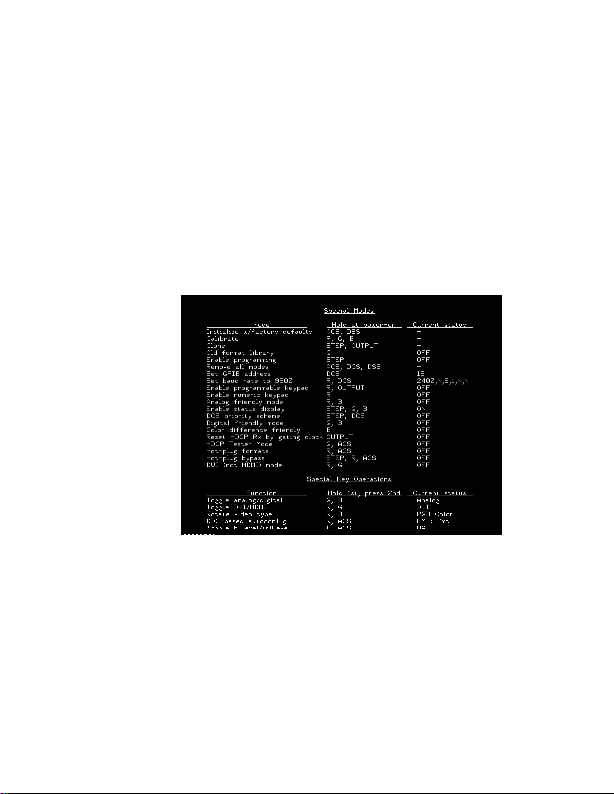
Summary of special modes
The following table describes the special operating modes, and how to configure the
modes using the physical controls or the command line interface.
Special mode Function Physical control Command
Initialize with factory
defaults
Calibrate Calibrates the generator. R, G, B
Re-initializes generator to factory defaults. Removes all special modes, deletes all custom
objects.
ACS, DSS
INIT
SCAL
SROP 32
Clone Copies configuration settings
from one generator to other
generators using a PCMCIA
card.
Old format library Displays old format names on
LCD.
Remove all modes Removes all special modes. ACS, DCS, DSS Set: SROP 0
Set GPIB address Sets the GPIB address. DCS Set: GPIB
Set baud rate to 9600 Sets baud rate of RS-232 port
to 9600 bps.
Enable programmable
keypad
Enable numeric keypad
Enables remote operation
through remote keypad.
Step, Outputs Set: SROP 64
Rst: SROP 0 64
G Set: SROP 1
Rst: SROP 0 1
addr
Rst: INIT
R, DCS Set: SROP 256
Rst: SROP 0 256
R, OUTPUT Set: SROP 512
Rst: SROP 0 512
R Set: SROP 128
Rst: SROP 0 128
Analog friendly mode Causes all digital formats to
output analog video signal.
Enable status display Provides additional information
on LCD (analog/digital and
color depth).
DCS priority scheme Changes priority scheme for
putting CS on separate VS and
HS sync outputs when any digital composite sync (DCS) type
is selected
Digital friendly mode Causes all analog formats out-
put digital signal
Color difference
friendly
Reset HDCP Rx gating
clock
802BT/802R Video Test Generator User Guide 19
Outputs digital YCbCr for television formats.
Resets the receiver, and gates
off transmitter clock and data.
R, B Set: SROP 4
Rst: SROP 0 4
Step, G, B Set: SROP 8
Rst: SROP 0 8
Step, DCS Set: SROP 4096
Rst: SROP 0 4096
G, B Set: SROP 2
Rst: SROP 0 2
B Set: SROP 2048
Rst: SROP 0 2048
Outputs Set: SROP 16
Rst: SROP 0 16
Page 30

Special mode Function Physical control Command
HDCP tester mode Enables HDCP testing. G, ACS Set: SROP 8192
Rst: SROP 0 8192
Hot plug formats Auto-configures generator for-
mat knob list based on EDID in
response to hot plug.
DVI mode (disable
HDMI)
Hot plug bypass Bypasses hot plug detection
Outputs DVI on HDMI connector.
and auto-configuration of the
generator.
Special key operations summary
The following table describes modes that can be enabled while the generator is running,
and the physical controls and comands for using the modes.
Mode Function
Toggle analog/digital Outputs either digital or ana-
log.
R, ACS Set: SROP 16384
Rst: SROP 0 16384
R, G Set: SROP 32768
Rst: SROP 0 32768
Step, R, ACS Set: SROP 65536
Rst: SROP 0 65536
Physical control
(hold 1st & press
2nd) Command
G, B AVST x; DVST x
Rotate video type Outputs either RGB, color dif-
ference, or monochrome.
DDC-based auto-configuration
Toggle biLevel/triLevel Toggles between tri-level and
Auto-configures generator format knob list based on EDID.
bi-level syncs for analog HDTV
formats with tri-level sync type.
R, B
R, ACS
B, ACS TSPG x
20 Chapter 1 Getting Started
Page 31

About Video Generator Manager
Video Generator Manager (VGM) is a Microsoft Windows-based program used to operate
the generator from a computer.
VGM features
VGM supports the following functions.
• Creating custom test sequences.
• Creating customized Image or Format knob lists.
• Creating custom formats or modifying existing formats.
• Creating custom images or modifying existing images.
• Archiving custom data.
• Upgrading the generator firmware.
• Re-initializing a generator.
• Calibrating a generator.
• Downloading a bitmap image to a generator.
802BT/802R Video Test Generator User Guide 21
Page 32

Installing VGM
For information about using VGM, see the VGM online help.
VGM is available on the Resource CD included with the generator, and from
http://www.quantumdata.com/support/downloads/.
To install VGM:
1. Log onto Windows with Administrator privileges.
2. Do one of the following:
• On the Resource CD, double-click the setup.exe file to begin the installation.
• On the Quantum Data Web site, click the setup.exe file to begin the installation.
3. Follow the on-screen instructions.
22 Chapter 1 Getting Started
Page 33

2 Testing Video Displays
Topics in this chapter:
• General video display testing procedure
• Testing analog computer (IT) CRTs
• Testing digital computer (IT) FPDs
• Testing analog composite video SDTV (CE) CRTs
• Testing analog component video SDTV (CE) CRTs
• Testing digital component video HDTV (CE) flat panel displays
802BT/802R Video Test Generator User Guide 23
Page 34

General video display testing procedure
This section provides an overview of the video testing process, which involves connecting
the generator to the display under test, selecting a format appropriate for the display, and
then selecting images to exercise the display to ensure proper functioning.
Making physical connections
Use the following table to connect the generator with display under test.
Display type Signal type Cable
Information
Technology
(IT)
Computer - VESA (DMT,
CVT)
Computer - VESA DDWG Digital component RGB DVI to DVI
Analog component RGB VGA to VGA
Consumer
Equipment
(CE)
1. Optional cable available from Quantum Data.
SDTV - ITU-470-6 baseband
SDTV - ITU-470-6 baseband
SDTV - CEA-861B Analog component YPbPr VGA to RCA
HDTV - CEA-861B Digital component DVI
HDTV - CEA-861B Digital component HDMI
Setting the video output mode
If the application involves testing similar displays with one type of video signal output for
extended periods of time (for example, in a production environment), use one of the
following modes:
• Digital Friendly mode – Digital formats are output without change, while analog
formats are temporarily switched to digital. This mode is available only if the generator
has a digital option (DVI, LVDS, or HDMI) installed.
Analog composite CVBS BNC to RCA 75 Ohm
Analog composite S-Video S-Video (miniDin to
MiniDin)
1
DVI to DVI, or HDMI to
RGB
RGB and YCbCr
DVI
HDMI to HDMI
• Analog Friendly mode – Analog formats are output without change, while the digital
formats are temporarily switched to analog.
For information about using these modes, see “Summary of special modes” on page 19.
When you need to test various video signal outputs and color encoding methods (for
example, in a repair center), disable all friendly modes, and enable the Status Display
mode (see “LCD” on page 7) so that you can determine the current configuration. Then,
24 Chapter 2 Testing Video Displays
Page 35

hold down the G key while pressing and releasing the B key to switch between digital and
analog outputs. The table below shows the AVST and DVST command settings for analog
and digital outputs.
Video Signal Interface AVST
Analog YYY Grayscale 1 0
Analog RGB Color 2 0
CVBS or S-Video Grayscale 3 0
CVBS or S-Video Color 4 0
Analog YPbPr SDTV Color 6 0
Analog YPbPr HDTV Color 7 0
Digital YYY Grayscale 0 9
Digital RGB Color 0 10
Digital YCbCr SDTVColor 0 13
Digital YCbCr HDTV Color 0 14
Selecting video formats
This section explains how to configure the generator to output video formats that are
supported by the device being tested.
DVST
Note: You can create your own formats. See “Creating custom formats” on page 63 for
details. Additionally, you can create your own Format knob lists. See “Editing Format knob
lists” on page 67 for details.
Selecting formats automatically
When testing EDID-compatible displays, the generator can automatically update the
Format knob list (list of format names shown on the LCD) to include only formats
supported by the display under test. Depending on the output used, the generator can do
this on demand, or automatically when a display is connected.
To update the Format knob list on demand:
1. Connect the display you want to test with the generator.
2. Hold down the R key, and then press and release the ACS key. This puts the generator
into either Analog Friendly or Digital Friendly mode based on the EDID that the
generator receives.
3. Turn the Format knob to choose a format. Only formats supported by the display are
listed.
802BT/802R Video Test Generator User Guide 25
Page 36

To update the Format knob list automatically when a dis play is connected:
1. Connect the display you want to test with the DVI or HDMI connector on the generator.
(Analog outputs do not support this feature.)
2. Turn the generator off.
3. Hold down the R and ACS keys while starting the generator, until hot plug formats
displays on the LCD.
Note: The generator is now in Digital Friendly mode.
4. Turn the Format knob to choose a format. Only formats supported by the display are
listed.
5. Connect a different device to automatically update the Format knob list again.
Selecting formats manually
When testing a display that is not EDID-compliant, you must manually choose formats
from the generator that are supported by the display.
To do this:
• Identifing the type of display (composite television, component standard definition
television, component high definition television, computer equipment, or other specialty
display).
• Check the specifications of your display for supported formats.
• Learn how the format library is organized, and how formats are named (see below).
• Turn the Format knob to try formats from the appropriate format category. Try the
DMT0660 (VGA) format if you are not sure of which formats to use.
Understanding the format library
After connecting the generator with the display under test, turn generator on, and select a
video format.
This section describes how to choose a video format, from the list of formats built into the
generator, for the display you are testing. A format defines a set of video, timing and sync
parameters for a specific device or standard.
A summary of the format naming convention is provided. For a detailed description of the
naming conventions, see to “Format naming conventions” on page 56.
Organization of format library
The generator has several built-in formats to test a broad range of display types. These
formats are grouped in the following categories:
26 Chapter 2 Testing Video Displays
Page 37

• Composite television formats
• Component standard definition television formats
• Component high definition television
• Computer display formats
• Military and medical display formats
• Miscellaneous formats
When you turn the Format knob, the formats are listed in the order shown above.
Composite television f ormats
Composite television formats are named by the standards defining them. The first three to
five characters of the format name indicate the color coding scheme. The first set of
characters refers to the standard. The next characters are optional and indicate
adjustments to the format. Examples of these formats are:
• NTSC (North American TV)
• PAL (European TV)
• NTSC-J - (where J refers to a Japan standard per NTSC without 7.5 IRE setup)
• PAL-N (where N indicates 3.58205625 MHz color sub-carrier)
• PAL# (where # indicates that the sampling rate is reduced to achieve square pixels)
Component standard definition television formats
Component SDTV formats are applicable in the case of RGB, YPbPr. These formats are
named by their vertical resolution, scanning method, and frame rate. The initial characters
indicating the resolution are followed by the scanning method. The two characters
following the scanning method indicate the frame rate. A typical example of component
standard or definition TV video format is:
• 480i2x30 (for a vertical resolution of 480 pixels with interlaced scanning and a 30 Hz
frame refresh rate; 2x indicates that the pixels are double-clocked for DVI compatibility).
Component high definition television formats
Component high definition television formats, like the standard definition television
formats, are named by their vertical resolution, scanning method, and frame rate. These
formats are applicable in the case of RGB, YPbPr, and YCbCr. These initial characters
indicating the resolution are followed by the scanning method. The two characters
following the scanning method indicate the frame rate. A typical example of component
high definition TV video format is:
• 1080i30 (for a vertical resolution of 1080 active vertical lines with interlaced scanning
and a 30 Hz frame refresh rate).
802BT/802R Video Test Generator User Guide 27
Page 38

Computer display formats
Computer display formats are assumed to use progressive scanning. Computer format
names consist of four blocks. The initial three characters indicate the vendor ID using the
EISA ID (for example, IBM, SUN, and VSC) or the standard body or acronym (for example,
SMT, DMT, GTF, CEA, and EIA). The next two characters provide the first two digits of the
horizontal resolution in pixels. Following the horizontal resolution are two characters which
indicate the frame rate. The final character indicates the aperture, which is used only if the
aperture is not 1.33 (A). The following are examples of computer display formats:
• VSC1275 for Viewsonic 1280 by 1024 at 75 Hz
• DMT0685 for Discrete Monitor Timing with 680 by 480 at 85 Hz
Viewing format parameters
You can use the Format image or VGM to view detailed information about formats in the
generator.
To view formats parameters using VGM:
• Open each format in the Font Editor.
• Generate a detailed format listing.
Selecting images
Once you have determined the format or formats appropriate for testing the display you
will apply a series of images suitable for evaluating the display. Of primary importance is
determining what type of display you are testing (for example, CRT or digital flat panel
display). You must also determine if you are testing composite TV and use images
appropriate for these formats and video types.
Each image in the generator’s library is intended to test one or more attributes of a
particular display type and video type.
Note: You can create your own images. See “Creating custom images” on page 75 for
details. Additionally, you can create your own custom Image knob lists. See “ Editing Image
knob list” on page 81 for details.
Refer to the VGM online help for instructions.
28 Chapter 2 Testing Video Displays
Page 39

The table below provides a summary of display characteristics and the images used to
evaluate them. For details on the images and display attributes, see Appendix B, “Image
Reference.”
Display type Display test Recommen de d im ages
Analog CRT Geometry (pin and barrel,
linearity)
Focus Focus_@6, Focus_@7, Focus_@8,
Photometry (chrominance,
contrast, levels)
Luminance SMPTE133 (grayscale), Grays5, Grays9,
Gamma correction SMPTE133 (checkerbox)
Resolution BurstTCE, Burst (TV formats only), Grill_11,
Pulse (CE SDTV) PulseBar
Centering Outline0, Outline1, Outline2, Outline3
Static images
Hatch (TVHatch, Hatch_16, Hatch_20), Cir-
clesL, Geom_1 - Geom_5, SMPTE133
Focus_@9, Text_9, Text_9T, Text_11,
Text_12T, Text_16
Flat, Flat07, Flat13, Flat20, Flat27, Flat33,
Flat40, Flat47, Flat53, Flat60, Flat67, Flat73,
Flat80, Flat87, Flat93, FlatGray, Flat_01,
Flat_02, Flat_03, Flat_04, Flat_05, Flat_06,
Flat_07, Flat_08, Flat_09, Flat_10, Flat_11,
Flat_12, Flat_13, Flat_14, Flat_15, Flat_16,
Ramp_B, Ramp_G, and Ramp_R,
ColorBar, SMPTEbar, TVBar100 & TVBar_75
(TV formats only)
Grays11, Grays16, Grays32, Grays64
Grill_15, Grill_22, Grill_33, Grill_44
Voltage Regulation Regulate
Electromagnetic Interference
EMITest1, EMITest2, EMITest3, EMITest4,
EMITest5
802BT/802R Video Test Generator User Guide 29
Page 40

Display type Display test Recommen de d im ages
Digital flat panel
(fixed pixel display)
Pixel anomalies (stuck pixels, misc sampling)
Flat, Raster, Ramp_B, Ramp_G, and Ramp_R,
Focus_@6, Focus_@7, Focus_@8,
Focus_@9, Text_9, Text_9T, Text_11,
Text_12T, Text_16
Photometry (chrominance,
contrast, levels)
Luminance SMPTE133 (grayscale), Grays5, Grays9,
Centering Outline0, Outline1, Outline2, Outline3
Resolution BurstTCE, Grill_11, Grill_15, Grill_22, Grill_33,
Persistence Animated images: Persist, Cubes, SlideX
Flat, Flat07, Flat13, Flat20, Flat27, Flat33,
Flat40, Flat47, Flat53, Flat60, Flat67, Flat73,
Flat80, Flat87, Flat93, FlatGray, Flat_01,
Flat_02, Flat_03, Flat_04, Flat_05, Flat_06,
Flat_07, Flat_08, Flat_09, Flat_10, Flat_11,
Flat_12, Flat_13, Flat_14, Flat_15, Flat_16,
Ramp_B, Ramp_G, and Ramp_R, ColorBar,
SMPTEbar, SMPTE133
Grays11, Grays16, Grays32, Grays64
Grill_44
30 Chapter 2 Testing Video Displays
Page 41

Testing analog computer (IT) CRTs
This section describes how to test analog computer (IT) displays.
To test an analog computer CRT:
1. Use a standard VGA cable to connect the VGA connector on the generator with the
VGA connector on the display under test.
2. Calibrate the generator by holding down the R, G and B keys while starting the
generator. See “Calibrating the generator” on page 47.
You can also calibrate the generator by entering the following command:
SCAL
When calibrating the generator, if you load the analog outputs (as they will be loaded
when conducting testing) then the calibrations will be slightly more accurate. This is not
required however. Also, loading the unused outputs with 75 ohms will optimize signal
damping.
3. (Optional) Enable the Status Display mode and Analog Friendly mode (see “Special
operating modes” on page 18). The Analog Friendly mode ensures that the generator
will output an analog signal. The Status Display mode enables you to view the current
output characteristics on the LCD.
4. Determine the formats to test (see “Selecting formats automatically” on page 25).
5. (Optional) To view the EDID on the display, use the Image knob to select the EdidData
image and follow the directions on the display. You may wish to view the EDID data to
verify that the formats required for testing are specified in the EDID.
Alternatively, you can load the image with the following command:
IMGL EdidData; IMGU
6. Determine additional formats to test based on the resolution of the display. The VESA
formats are shown below:
Standard Quantum Data format name
VGA DMT06xx
SVGA DMT08xx
XGA DMT10xx
SXGA DMT12xx
UXGA DMT16xx
QXGA DMT20xx
QSXBA DMT25xx
802BT/802R Video Test Generator User Guide 31
Page 42

Determine the images to test:
For analog CRTs you typically want to select images to test for geometry, focusing,
photometry, resolution, cross talk, EMI, and regulation characteristics. For more details on
what images test these specific display attributes, see “Selecting images” on page 28 or
Appendix B, “Image Reference.”
Verify the test set-up:
1. Using the Format knob, select one of the formats you have identified.
Alternatively, you can load the format with the following command:
FMTL format_name; FMTU
2. Using the Image knob, select a suitable image such as ColorBar. Verify that the display
is presenting the image to ensure that the generator is sending a valid signal to the
display.
Alternatively, you can load the image with the following command:
IMGL ColorBar; IMGU
Test the display:
1. Using the Format knob, select the first test format identified.
Alternatively, use these commands to load the format:
FMTL format_name; FMTU
2. Using the Image knob, select the first test image.
Alternatively, you can also load an image with the following command:
IMGL image_name; IMGU
3. Repeat steps 1 and 2 for all formats and test images. Use the following guidelines to
verify proper operation:
• When testing geometry with the Hatch images (for example, Hatch20) look for
distortion with concave or convex lines near the periphery of the display. Look for
irregular spacing on the cross hatch patterns.
• When testing photometry such as chrominance, use the ColorBar, SMPTE133, or
SMPTEbar images. Look for missing bars which may indicate a dead or
unconnected channel. Also, look at the transition between the bars; they should be
sharp and distinct. Each bar also should be uniform in color and intensity across its
entire width.
• To test luminance, you can use the SMPTE133 (grayscale portion) image. To test
gamma correction, you can use the SMPTE133 (checkerbox portion) image. The
detailed methods for verifying these parameters on the SMPTE133 image are
provided in Appendix B, “Image Reference.”
• When testing focus with the Focus or Text images, the characters in all areas of the
display should be well-formed and in focus.
32 Chapter 2 Testing Video Displays
Page 43

• When testing resolution with the Grill images, you should be able to see individual
and distinct stripes in all areas of the display at all four resolutions.
• When testing for centering use the Outline images. For detailed methods for
verifying centering with the Outline images, see Appendix B, “Image Reference.”
• When testing for high voltage regulation with the Regulate image, observe the
outline at the edges of the image. They should stay in place and not pull away from
the area of the large white blinking patch (when it appears).
Note: You can customize your generator to run through a specified set of formats and
images automatically or manually b y creating test sequences. See to “Creating a test
sequence” on page 87 for details.
802BT/802R Video Test Generator User Guide 33
Page 44

Testing digital computer (IT) FPDs
This section describes how to test digital computer (IT) displays.
To test a digital FPD:
1. Use a DVI-I cable to connect the DVI output on the generator with the DVI connector on
the display under test.
2. Place the generator in Digital Friendly mode by holding down the G and B keys while
starting the generator.
Alternatively, you can set the Digital Friendly mode by entering the following command:
SROP 2 4; ALLU
The Digital Friendly mode ensures that the generator will output a digital signal on the
DVI connector, when selecting analog formats from the format library.
3. Determine the formats to test. Auto-select the formats to test by enabling the
generator’s DDC-based auto configuration. See “Selecting formats automatically” on
page 25 for instructions.
4. (Optional) To view the EDID on the display, use the Image knob to select the EdidData
image and follow the directions on the display. Verify that the EDID specifies the formats
required for testing.
Alternatively, you can load the image with the following command:
IMGL EdidData; IMGU
5. Determine which images to test. For digital flat panel displays, you typically want to
select images to test for pixel anomalies, persistence, photometry and resolution
related problems. For more information, see “Selecting images” on page 28 or
Appendix B, “Image Reference.”
Verify the test set-up:
1. Using the Format knob, select one of the formats you have identified.
Alternatively, you can load the format with the following command:
FMTL format_name; FMTU
2. Using the Image knob, select a suitable image such as SMPTE133. Verify that the
display is presenting the image to ensure that the generator is sending a valid signal to
the display.
Alternatively, you can load the image with the following command:
IMGL SMPTE133; IMGU
Test the display:
1. Using the Format knob, select the first test format identified.
34 Chapter 2 Testing Video Displays
Page 45

2. Using the Image knob, select the first test image.
3. Repeat steps 1 and 2 for all formats and test images. Use the following guidelines to
verify proper operation:
• When testing photometry such as chrominance, use the ColorBar, SMPTE133, or
SMPTEbar images. Look for missing bars which may indicate a dead or
unconnected channel. Also, look at the transition between the bars; they should be
sharp and distinct. Each bar also should be uniform in color and intensity across its
entire width.
• To test luminance, you can use the SMPTE133 (grayscale portion) image. To test
gamma correction, you can use the SMPTE133 (checkerbox portion) image. The
detailed methods for verifying these parameters on the SMPTE133 image are
provided in Appendix B, “Image Reference.”
• When testing for centering use the Outline images. The detailed methods for
verifying centering with the Outline images (Outline0, Outline1, Outline2, Outline3)
are provided in Appendix B, “Image Reference.”
• When testing resolution with the Grill images, you should be able to see individual
and distinct stripes in all areas of the display at all four resolutions.
• When testing for pixel anomalies use the Flat, Raster and Ramp images. Use the
Raster and Flat images to look for pixels that may be stuck On or Off, respectively.
The luminance should increase uniformly for the Ramp image. Also, look for
sparkles indicating problems with sampling.
• When testing for persistence with the animated images (for example, Cubes and
Persist), look for bleeding or trails in the wake of the moving object.
Note: You can customize your generator to run through a specified set of formats and
images automatically or manually b y creating test sequences. See “Creating a test
sequence” on page 87 for details.
802BT/802R Video Test Generator User Guide 35
Page 46

Testing analog composite video SDTV (CE) CRTs
This section describes how to test CRT composite televisions with analog composite video
inputs.
To test analog composite video SDTV:
1. Use a standard coax cable to connect the TV BNC connector on the generator with the
display under test.
Or, use an S-video cable to connect the SVIDEO connector on the generator with the
S-Video input on the display under test.
2. (Optional) Place the generator in Analog Friendly mode by holding down the R and B
keys while starting the generator (see “Special operating modes” on page 18).
The Analog Friendly mode ensures that the generator will output an analog signal.
3. Determine which composite television standard you need, such as NTSC or PAL, and
then select the formats compatible with the standard. Typically, you would test all the
formats in the family of formats for a standard.
4. Determine the images to test. For analog CRTs you typically want to select images to
test for geometry, focusing, photometry, resolution, cross talk, EMI, and regulation
characteristics. For more details on what images test these specific display attributes,
see “Selecting images” on page 28 or Appendix B, “Image Reference.”
Verify the test set-up:
1. Using the Format knob, select the first NTSC or PAL format.
Alternatively, you can load the format with the following command:
FMTL format_name; FMTU
2. Using the Image knob, select a suitable image such as SMPTEBar. Verify that the
generator is sending a valid signal to the display and that the display is presenting it.
Alternatively, you can load the image with the following command:
IMGL SMPTEBar; IMGU
Test the display:
1. Using the Format knob, select the first test format.
2. Using the Image knob, select the first test image.
Note: You can customize your generator to run through a specified set of formats and
images automatically or manually b y creating test sequences. See “Creating a test
sequence” on page 87 for details.
3. Repeat steps 1 and 2 for all formats and test images. Use the following guidelines to
verify proper operation:
36 Chapter 2 Testing Video Displays
Page 47

• When testing geometry with the Hatch images (for example, TVHatch and
Hatch20) look for distortion with concave or convex lines near the periphery of the
display. Look for irregular spacing on the cross hatch patterns.
• When testing photometry such as chrominance, use the TVBar100 & TVBar_75
(TV formats only), TVSplBar, SMPTE133 or SMPTEbar images. Look for missing
bars which may indicate a dead or unconnected channel. Also, look at the transition
between the bars; they should be sharp and distinct. Each bar also should be
uniform in color and intensity across its entire width.
• When testing focus with the Focus images, the characters in all areas of the display
should be well-formed and in focus.
• When testing resolution with the Grill images, you should be able to see individual
and distinct stripes in all areas of the display at all four resolutions. When testing
for resolution with the Burst image, the peak intensities of the all of the bursts
should match the white reference level. The darkest portions between the peaks
should match the black reference level.
• When testing for centering, use the Outline and TVoutLin images. The detailed
methods for verifying centering with the Outline images (Outline0, Outline1,
Outline2, Outline3) are provided in Appendix B, “Image Reference.”
• When testing for high voltage regulation with the Regulate image, observe the
outline at the edges of the image. They should stay in place and not pull away from
the area of the large, white blinking patch (when it appears).
802BT/802R Video Test Generator User Guide 37
Page 48

Testing analog component video SDTV (CE) CRTs
This section describes how to test CRT televisions with standard definition component
video inputs.
To test an analog component video SDTV display:
1. Use a VGA-to-RCA cable to connect the VGA connector on the generator with the
YPbPr inputs on the display under test.
Or, if your generator has optional component BNC connectors, use a BNC to RCA
cable to connect the BNCs on the generator with the RCA connectors on the display
under test.
2. Identify the component television formats to test. These formats are listed after the
composite television formats in the generator’s default Format knob list. Begin with the
first format in the range of standard definition component television formats (480i).
3. Determine additional formats to test based on the resolution of the television display.
The television specification sheet will provide information on what resolutions to test. It
is necessary to test only those resolutions with the supported scanning type (typically,
interlaced for a standard definition television).
4. Determine the images to test. For analog CRTs you typically want to select images to
test for geometry, focusing, photometry, resolution, cross talk, EMI, and regulation
characteristics. For more details on what images test these specific display attributes,
see “Selecting images” on page 28 or Appendix B, “Image Reference.”
Verify the test set-up:
1. Using the Format knob, select the first component video format (480i).
Alternatively, you can load the format with the following command:
FMTL 480i; FMTU
2. Using the Image knob, select a suitable image such as SMPTE133. Verify that the
generator is sending a valid signal to the display and that the display is presenting it.
Alternatively, you can load the image with the following command:
IMGL SMPTE133; IMGU
Test the display:
1. Using the Format knob, select the first test format.
2. Using the Image knob, select the first test image.
Note: You can customize your generator to run through a specified set of formats and
images automatically or manually b y creating test sequences. See “Creating a test
sequence” on page 87 for details.
38 Chapter 2 Testing Video Displays
Page 49

3. Repeat steps 1 and 2 for all formats and test images. Use the following guidelines to
verify proper operation:
• When testing geometry with the Hatch images (for example, TVHatch and
Hatch20), look for distortion with concave or convex lines near the periphery of the
display. Look for irregular spacing on the cross hatch patterns.
• When testing photometry such as chrominence, use the TVBar100 & TVBar_75
(TV formats only), ColorBar, SMPTE133 or SMPTEbar images. Look for missing
bars which may indicate a dead or unconnected channel. Also, look at the transition
between the bars; they should be sharp and distinct. Each bar also should be
uniform in color and intensity across its entire width.
• To test luminance you can use the SMPTE133 (grayscale portion) image. To test
gamma correction you can use the SMPTE133 (checkerbox portion) image. The
detailed methods for verifying these parameters on the SMPTE133 image are
provided in Appendix B, “Image Reference.”
• When testing focus with the Focus or Text images, the characters in all areas of the
display should be well-formed and in focus.
• When testing resolution with the Grill images, you should be able to see individual
and distinct stripes in all areas of the display at all four resolutions.
• When testing for centering use the TVOutline and Outline images. The detailed
methods for verifying centering with the Outline images (Outline0, Outline1,
Outline2, Outline3) are provided in Appendix B, “Image Reference.”
• When testing for high voltage regulation with the Regulate image, observe the
outline at the edges of the image. They should stay in place and not pull away from
the area of the large white blinking patch (when it appears).
802BT/802R Video Test Generator User Guide 39
Page 50

Testing digital component video HDTV (CE) flat panel displays
This section describes how to test digital component video for HDTV flat panel displays.
To test a digital (DVI) component video HDTV display:
1. Use a standard DVI cable to the DVI connector on the generator and then to the DVI
connector on the television display under test.
Note: If the display under test has a DVI-D connector you will need a DVI-I to DVI-D
adaptor.
2. Place the generator in Digital Friendly mode by holding down the G and B keys while
starting the generator (see “Special operating modes” on page 18).
This mode ensures that the generator outputs a digital signal on the DVI connector,
even when selecting analog formats from the format library.
3. Identify the high definition component television formats to test. These formats are
listed after the composite television formats in the generator’s default Format knob list.
Begin with the first format (720p) in the range of high definition component television
formats. See “Selecting formats automatically” on page 25.
4. Determine additional formats to test based on the resolution of the television display.
The television product specification sheet will provide information on what resolutions
to test. It is necessary to test only those resolutions with the supported scanning type
(typically interlaced for a high definition television).
5. Determing which images to test. For digital television flat panel displays, you would
typically want to select images to test for pixel anomalies, persistence, photometry and
resolution related problems. For more details on which images test these specific
display attributes, see “Selecting images” on page 28 or Appendix B, “Image
Reference.”
Verify the test set up:
1. Using the Format knob, select the first HDTV video format (720p50).
Alternatively, you can load the format with the following command:
FMTL 720p50; FMTU
2. Using the Image knob, select a suitable image such as the SMPTE133 image. Verify
that the generator is sending a valid signal to the display and that the display is
presenting it.
Alternatively, you can load the image with the following command:
IMGL SMPTE133; IMGU
40 Chapter 2 Testing Video Displays
Page 51

Test the display:
1. Using the Format knob, select the first test format.
2. Using the Image knob, select the first test image.
Note: You can customize your generator to run through a specified set of formats and
images automatically or manually b y creating test sequences. See “Creating a test
sequence” on page 87 for details.
3. Repeat steps 1 and 2 for all formats and test images. Use the following guidelines to
verify proper operation:
• When testing photometry such as chrominence, use the ColorBar, SMPTE133, or
SMPTEbar images. Look for missing bars which may indicate a dead or
unconnected channel. Also, look at the transition between the bars; they should be
sharp and distinct. Each bar also should be uniform in color and intensity across its
entire width.
• To test luminance, you can use the SMPTE133 (grayscale) images. To test gamma
correction, you can use the SMPTE133 (checkerbox) image. The detailed methods
for verifying these parameters on the SMPTE133 Image are provided in Appendix
B, “Image Reference.”
• When testing for centering, use the Outline images. The detailed methods for
verifying centering with the Outline images (Outline0, Outline1, Outline2, Outline3)
are provided in Appendix B, “Image Reference.”
• When testing resolution with the Grill images, you should be able to see individual
and distinct stripes in all areas of the display at all four resolutions.
• When testing for pixel anomalies, use the Flat, Raster, and Ramp images. Use the
Raster and Flat images to look for pixels that may be stuck On or Off, respectively.
The luminance should increase uniformly for the Ramp image. Also look for
sparkles indicating problems with sampling.
• When testing for persistence with the animated images (Cubes and Persist), look
for bleeding or trails in the wake of the moving object.
802BT/802R Video Test Generator User Guide 41
Page 52

42 Chapter 2 Testing Video Displays
Page 53

3 Administrative Tasks
The chapter describes how to accomplish common administrative tasks. Most
administrative functions are supported through the front panel or command line interface.
However, upgrading firmware can only be achieved through VGM; it is not supported
through the front panel. Most administrative functions are supported through the VGM
application. See the VGM online help for information on performing these administrative
tasks through VGM.
Topics in this chapter:
• Displaying system information
• Restoring factory settings
• Calibrating the generator
• Cloning generators
• Installing firmware
• Memory management
802BT/802R Video Test Generator User Guide 43
Page 54

Displaying system information
Use the GenStats image to display information about the generator, including revision
levels of FPGA software installed. This image also list installed options.
To display information about generator:
1. Connect the generator with a display.
2. Choose a format supported by the display.
3. Turn the Image knob to select the GenStats image.
44 Chapter 3 Administrative Tasks
Page 55

Restoring factory settings
This section describes how to set and restore the generator system parameters.
System Parameters
The following system parameters are stored in the 802’s non-volatile system memory:
• The reference rate calibration factor. The 802 uses a crystal controlled oscillator as the
reference for all timing signals. The crystal frequency has a maximum error of ±50 ppm.
The 802 hardware and firmware is capable of compensating for this small amount of
error by applying a user set calibration factor. The factory default setting is 1.000 for the
calibration factor. Use the
• The maximum pixel clock rate used for error checking formats. All 802 generators will
operate, to some extent, at pixel rates beyond their spec sheet limits. The maximum
rate can be set to a higher limit if it is known that a particular unit will work reliably at
the higher limit. Use the
checking of analog formats.
RATC
command to set the pixel calibration factors.
JRAT
command to set the maximum pixel rate used for error
• The gamma correction flag. This flag determines whether individual formats can control
the application of gamma correction or if gamma correction is disabled regardless of a
format’s setting. The factory default setting is to allow gamma correction to be
controlled by individual formats. Use the
gamma correction flag.
GAMC
command to enable or disable the
Setting and restoring system parameters
There are two ways of changing the settings of these parameters:
• They can be restored to their default factory settings as part of a user initiated system
reset. This will also restore the entire format storage memory to its factory default
contents.
• A suitably equipped computer or terminal connected to one of the communications
ports can be used to set the parameters to user defined settings.
When the generator is reinitialized, each format in the standard library is tested
(one-at-a-time), to determine if the format parameters are fully supported by the generator.
This algorithm is necessary because the standard format library is used across all
generators. If there are some limitation the generator applies a format justification
algorithm. In these cases the generator stores a modified version of the format under a
similar name. If the format is beyond what can be corrected the format is left out of the
generator’s list of formats.
WARNING: The initializing the generator permanently and irreversibly removes all
user-created formats, custom images, test sequences and directories from memory.
802BT/802R Video Test Generator User Guide 45
Page 56

To re-initialize generator through system reset:
1. Hold down ACS and DSS while powering up the generator.
A confirmation message is displayed.
2. Press the Outputs key to continue, or press the Step key to cancel the operation.
To re-initialize and calibrate the generator using command interface:
1. Establish a terminal session with the generator (see page 14).
2. Enter the following command:
INIT
The generator then goes through a complete self-test and self-calibration procedure.
To re-initialize without calibrating the generator using the command line:
1. Establish a terminal session with the generator (see page 14).
2. Enter the following command:
BOIT
The generator is re-intialized.
46 Chapter 3 Administrative Tasks
Page 57

Calibrating the generator
The 802BT/R generator can calibrate itself. Once calibrated, the generator does not
require periodic calibration. There are no physical controls to adjust. All calibration is
electronic. Calibration factors are saved in non-volatile memory.
The calibration accuracy of the generator for analog video voltage swing is specified to be
±14mV (or ±2% for a nominal 700mV signal). Using a typical oscilloscope such as a
Tektronix VM700T, which might have a swing measurement accuracy of ±14mV, we
should expect readings between 674mV to 726mV.
You can also set the analog output calibration factors to values other than those set by the
generator's own self-calibration function. Each channel is calibrated using two
independent zero calibration points, and two independent slope calibration points.
Interpolation equations for the different video types are used to set the caldac values that
controls the output sync and voltage levels to the correct values.
Follow the procedures below to calibrate the generator.
To self-calibrate the generator using the front panel:
1. It is not necessary to load the outputs of a generator during self-calibration. However,
attaching a nominal load may yield a slight increase in accuracy.
2. Simultaneously depress all three R, G and B video gate keys and power cycle the
generator.
The LCD will display a special message indicating that it is about to do a
self-calibration.
3. Release the R, G and B video gate keys and the generator will begin its self-calibration
routine.
You will see calibration factors flash on the display. Observe the display for any error
messages that might occur. If an error message appears, make a note of it and call your
technical support representative for further assistance.
To self-calibrate the generator using the command interface:
1. Establish a terminal session with the generator. See “Setting up a terminal connection
with the generator” on page 14.
2. Enter the following command:
SCAL
The generator then goes through a complete calibration procedure.
To view analog calibration factors:
1. Enter the following commands to view the analog video Red, Green, Blue calibration
factors:
802BT/802R Video Test Generator User Guide 47
Page 58

CALF?
The generator presents the following in response:
1089, 2589, 1993, 3223, 1148, 2633, 2059, 3279, 1000, 2505, 1990,
3219, 793, 787, 3382, 3509
Calibrating frequency
All frequencies associated with the generator are derived from a common frequency
reference, which can be calibrated using the rate calibration command RATC.
To reduce all frequency errors to zero:
1. Measure any convenient frequency from the generator using a very accurate frequency
counter.
For example, measure the horizontal TTL separate sync frequency with the DMT0660
format loaded and the horizontal rate temporarily set to 100KHz. Enter the following:
FMTL DMT0660; HRAT 100E3; ALLU
2. Measure the TTL horizontal sync frequency with the frequency counter.
3. Divide the frequency that you expect by the frequency that you measure on the
frequency counter and enter that ratio using the
RATC
command.
For example, if you measure 99.9955782499875 kHz, when you expect
100.000000000KHz, then divide 100.000000000KHz by 99.9950002499875kHz and
enter the following on the command line:
RATC 1.0000442194553987
This will raise all frequencies output by the generator and make them exact.
48 Chapter 3 Administrative Tasks
Page 59

Cloning generators
This section describes how to copy configuration settings from one generator to other
generators using a PCMCIA card. The entire block of battery backed user memory
(including video formats, custom test images and test sequences) is copied from one
generator to another using a suitable PCMCIA memory card.
The card you need is a Type 1, Battery Backed RAM PCMCIA card with at least 2 MB of
storage. These cards are available from synchrotech P/N PCM-SRW-AM002 2MB. Flash
or compact type memory cards will not work.
Note: See VGM online help for procedures for cloning generators using VGM.
To clone a generator using PCMCIA card:
1. Install the same firmware version on the source and target generators.
Note: This procedure can only be used when the firmware of the source and target
generators are the same. To verify the firmware version, load the GenStats image.
2. Insert PCMCIA card into the source generator.
3. Hold down the Step and Outputs keys while starting generator.
4. Choose WR (press Outputs key) to copy the generator configuration to the card.
The generator displays a Done message when it is done writing to the card.
5. Transfer the PCMCIA card to the second generator.
6. Hold down the Step and Output keys while starting generator.
7. Choose RD (press Step key) to copy the configuration data from the card to the
generator.
All user-created objects on the target generator will be deleted. To cancel the operation,
press the ACS key.
8. Hold down the ASC, DCS, and DSS keys while starting the generator to return the
generator to normal operating mode.
802BT/802R Video Test Generator User Guide 49
Page 60

Installing firmware
Firmware upgrades are available at http://www.quantumdata.com/support/downloads/.
Important: Always backup any custom ob jects (formats, images) stored on the gener ator
before installing an upgrade. The firmware installation re-initializes the generator, which
deletes any custom objects. After installing the firmware, you can restore custom objects.
Firmware upgrades require the use of VGM. Please refer to the VGM online help for
procedures on upgrading the generator.
50 Chapter 3 Administrative Tasks
Page 61

Memory management
The generator includes commands to manage its internal memory resources. These
commands or useful if the generator exhibits degraded performance or other anomolies.
To verify and correct memory related anomolies:
1. Check the generator’s memory for corruption by running a memory self test:
MEMT // runs the memory self test
MEMT? // returns the results of the memory self test
1 // returned value from the memory self test
A value of “0” indicates no memory corruption or inconsistency was found. A value of
“1” indicates that there is a memory anomoly.
2. If the memory self test reveals a memory corruption, re-initialize the generator:
BOIT // re-initializes the generator
3. If the memory self test does not reveal a memory corruption, check to see if there is
enough free memory and contiguous memory:
MEMF? // queries for the free memory
808320 // returns the amount of free memory
MEML? // queries for the largest contiguous block of free memory
816568 // returns the largest contiguous block of free memory
If the amount of memory is low or the amount of contiguous memory is low the memory
should be compacted.
4. Compact the generators memory:
MEMC // compacts the memory
MEML? // queries for the largest contiguous block of free memory
818280 // should show larger block of contiguous free memory
802BT/802R Video Test Generator User Guide 51
Page 62

52 Chapter 3 Administrative Tasks
Page 63

4 Working with Formats
Topics in this chapter:
• Overview
• Format library
• Format naming conventions
• Creating custom formats
• Editing Format knob lists
• Configuring DCS priority scheme
• Creating format aliases
802BT/802R Video Test Generator User Guide 53
Page 64

Overview
The generators enable you to create your own formats and edit the Format knob list
through the Video Generator Manager (VGM) application and the command line interface.
Please refer to the VGM online help for details on procedures for these functions
performed through VGM. This chapter provides procedures for customizing formats
through the command line interface.
The following functions are provided:
• Creating formats. If the application environment requires constant switching between
video outputs, for example, you can build your own library of customized formats that
individually select which video output is driven via the proper setting of AVST and DVST
parameters.
• Editing the Format knob list. You can edit the Format knob list to include any
combination of built-in and user-defined formats. The default operating mode of the 802
uses the Format knob to select formats from a list of built in formats.
• Creating aliases. You can assign your own names to formats using aliases.
54 Chapter 4 Working with Formats
Page 65

Format library
The generator has a built-in library of formats. The same format library is used for all 802
models. The formats are stored in read-only memory (ROM) along with the generator’s
operating code.
Compatibility
Some formats are for displays and graphics systems that may not be compatible with a
specific generator model. Attempting to load an incompatible format will give you an error
message. If a format has too high of a pixel rate, a modified version of the format can be
created with reduced horizontal timing parameters that bring the pixel clock rate below the
limit of the generator. The horizontal and vertical rates however are correct. This lets you
light-up a display and verify most of its operation. These modified formats can be created
through the FMTJ command which references a global parameter (JRAT) that determines
the bandwidth of the generator.
802BT/802R Video Test Generator User Guide 55
Page 66

Format naming conventions
The names used in the built-in format library have been updated for the generator. Many
format names on previous versions of the 802 generators have been renamed to more
closely match the naming conventions used in the display industry or in the appropriate
standards. There are three sets of naming conventions described in this section: 1)
Composite television formats, 2) Component television formats, and 3) Computer display
formats. In addition, several miscellaneous naming conventions are also described.
Composite television format names
Composite television formats apply to RF, D2, CVBS, and S-VIDEO signal interfaces.
Composite television format names consist of a three to five character color coding
scheme indicator followed by optional characters that indicate format adjustments.
Example
Color coding schemes
•NTSC
•PAL
• SECAM
Adjustments to the format
• 4x == sampling rate is four times the color sub-carrier frequency
• 44 == NTSC with color sub-carrier frequency of 4.43361875 MHz (as opposed to 3.58)
• # == sampling rate is reduced in order to make pixels square
• jp == NTSC-Japan (NTSC without 7.5 IRE setup)
• -M == PAL with 3.57561149 MHz color sub-carrier and M timing (M/PAL Brazil)
• -N == PAL with 3.58205625 MHz color sub-carrier (N/PAL Argentina, Paraguay,
Uruguay)
• -N == NTSC color encoding with N timing (NTSC-N)
• -60 == PAL format that allows NTSC tape playback on PAL TV (PAL-60)
• plusKKKK == Enhanced wide-screen PALplus TV transmission system
• p == progressive video game signal (for example, NTSCp or PALp)
56 Chapter 4 Working with Formats
Page 67

Common composite TV formats with sub-carriers and their respective standards:
• NTSC - ITU-R BT.470-6
• NTSC# - SMPTE 170M
• NTSC#KA - SMPTE 170M
• PAL - ITU-R BT.470-6
• PAL# - ITU-R BT.470-6
• PAL#KA - ITU-R BT.470-6
• SECAM
Component television format names
Component television formats are named by their vertical resolution and scanning
method. These formats apply to RGB, YPbPr, YcbCr and HD-SDI video. In component
television format naming, the first three or four characters indicate the active vertical lines
in the format, the next characters indicate the frame tracing method, and the last two
optional characters indicate the frame rate.
Example:
i2x480 29
Active
vertical
lines
Active vertical lines
• 480 (active lines with 525 total lines)
• 1035 (active lines with 1125 total lines)
Frame tracing methods
• p = progressive
• i = interlaced
• s = segmented frame interlace (e.g. 1080s24, where a 24p frame is segmented into two
interlaced fields occurring at twice the frame rate - scene changes only between field
pairs – also known as “48sF”)
Frame
tracing
method
Double
clocking
Frame
rate
• x = any – progressive, interlace, or segmented
802BT/802R Video Test Generator User Guide 57
Page 68

Double clocking
• i2x = double-clocked interlace (scene may change between fields) pixels are
double-clocked for DVI compatibility)
Frame rate
Frame rate is optional. If no frame rate is given, then the frame rates are assumed.
• 24 = 24 Hz
• 60 = 60 Hz
Common component TV formats
• 480pLH Component SDTV signal containing letterboxed 16x9 high-definition content
• 480pSH Component SDTV signal containing anamorphically under-sampled 16x9
content
Computer display format names
Computer display formats are assumed to use progressive scanning. In computer format
naming, the first three characters indicate the vendor ID using the EISA ID (for example,
IBM, SUN, VSC) or the display type, the next two characters indicate the approximate
horizontal resolution, the next two digits indicate the frame rate (which will be half the field
rate with interlace scanning), and the final character designates the aperture (used only
when the aperture is not A).
Example
Vendor ID (EISA)
• SMT for VESA (digital) Safe Mode Timing
• DMT for VESA Standard Discrete Monitor Timing
• GTF for VESA Generalized Timing Format standard
• CEA for Consumer Electronics Association
• EIA for Electronics Industries Association (CEA)
Approximate horizont al resolution examples
• 02 for 256 pixels
• 09 for 960 pixels
58 Chapter 4 Working with Formats
Page 69

• 12 for 1200 pixels
• 30 for 3072 pixels
Frame rate examples (half the field rate with interlace scanning)
• 48 for 48Hz
• 60 for 60Hz
• 75 for 75Hz
Aperture (used only when the aperture is not A)
See “Aperture designators” on page 59.
Common computer display formats
• VSC1275 for Viewsonic 1280 by 1024 at 75 Hz
• DMT0685 for Discrete Monitor Timing with 680 by 480 at 85 Hz
Aperture designators
Format names may include one or two characters that describe the aperture of the display.
These are listed below.
Aspect ratio
• Q = 1.00:1 Quadrate - MIL, Radiology (square, 512x512, 1024x1024)
• G = 1.25:1 Graphics workstation (5x4, 1280x1024, 1600x1280)
• A = 1.33:1 Academy (4x3, 640x480, 800x600, 1024x768, 1280x960, 1600x1200)
• B = 1.44:1 Big (13x9, IMAX™)
• T = 1.50:1 Three halves (3x2, 1152x768 Apple Computer)
• V = 1.56:1 PALplus WWS case #2 (14x9, see ITU-R BT.1119)
• D = 1.60:1 VESA CVT proposed (16x10, 1728x1080, 1280x800)
• E = 1.67:1 European film (15x9 or 5x3, 1200x720, 1280x768, 1800x1080, a.k.a. “1.66”)
• H = 1.78:1 High-definition image (16x9, 1280x720,1920x1080)
• F = 1.85:1 US film (320x173, 1280x692, 1920x1038)
• U = 2.00:1 Univisum™ (2x1, 1280x640, 1920x960)
• C = 2.39:1 CinemaScope™ (160x67, 1280x536, 1920x804, a.k.a. “2.35”, was 2.35
before 1971)
Content fitting operators
• N = Natural (do nothing)
802BT/802R Video Test Generator User Guide 59
Page 70

• L = Letterbox (linear scale to fit one axis, center w/black bars in other)
• Z = Zoom (blow- up to fill destination aperture with cropping, or LI )
• S = Scope (under-sample content horizontally)
• W = Widescreen (over-sample content horizontally)
• J = Justify (non- linear horizontal expand – more near edges)
• K = Keep safe (shrink to avoid cropping – provide safe title)
• P = Pan & Scan (truncate)
• M = Mirror (horizontally – rear projection)
Other Modifiers
• I = Inverse (undo operator; for example, S = Scope and SI = Inverse Scope)
• O = Orthogonally (rotate operator effect or aperture 90 degrees)
• X = Wildcard or special
Using legacy format names
You can configure the generator to display names using conventions from older generator
models.
Important: Configuring the generator to use legacy names will delete all user-defined
video formats currently stored in the gener ator. T herefore, it is important to back u p the user
data files from the generator to disk and then restore them bac k to the gener ator . V GM can
be used to backup the generator.
To display legacy format names:
1. Turn the generator off.
2. Hold down the G key, and then power on the generator.
The following message appears on the front panel LCD.
3. Release the G key. This setting is retained throughout subsequent power cycles.
To re-assert the default format names you must reinitialize the generator:
1. Turn the generator off.
2. Hold down the ACS and DSS keys and then power on the generator.
60 Chapter 4 Working with Formats
Page 71

Viewing the format library
You can view the list of formats available in the generator using VGM or the command line
interface. Please refer to the VGM online help for instructions on using VGM to view the
format list.
To display the format list:
1. Establish a terminal session with the generator.
2. Load the default format directory (fmt) or custom format directory by entering the
following command:
DIRL fmt
3. List the contents of the format directory by entering the following command:
NAMQ? 1 200 // lists the formats from the first format through 200
Viewing format details
You can view the format parameters of any standard or custom format using VGM or the
command line interface. Please refer to the VGM online help for instructions on using VGM
to view format details. Use the following procedure to view the detailed format information
through the command line interface.
To view formats parameters using the Format image:
1. Connect the generator with a display.
802BT/802R Video Test Generator User Guide 61
Page 72

2. Load the Format image.
Information about the current format is displays.
3. Press the Step key, then turn Image knob to view additional formats.
To display individual format parameters:
1. Establish a terminal session with the generator.
2. Load the format whose parameters you want to view by entering the following
command:
FMTL format; FMTU //specify a valid format name
3. Enter the format parameter(s) you want to view. For example, to view the horizontal
resolution, vertical resolution, horizontal period, and analog video sync type, enter the
following command:
HRES? VRES? HTOT? AVST?
The generator responds with the information in sequence as shown below:
640;480;800;2
62 Chapter 4 Working with Formats
Page 73

Creating custom formats
You can create new signal formats for the generator and add them to non-volatile memory.
You can create formats through VGM or by using a command line interface (either the
RS-232 port or the IEEE-488 port). The recommended procedure for creating new formats
is to use VGM. VGM contains the algorithms for ensuring compatibility between format
parameters where there are dependencies in their respective values. Please refer to the
VGM online help for information about creating formats using VGM.
Determining the signal specifications of the display
Your custom format will be based on the specifications of the display under test. Typically,
you can find the information required for the format in the detailed specification sheet for
the display. At a basic level, you must determine if you are working with an analog or a
digital display. An analog display can show an endless range of colors or shades of gray.
Analog displays normally accept video signal levels in the 1 Vp-p range. Digital displays
are more limited and can display only a few gray levels or a limited number of pre-defined
colors. These displays normally accept TTL video signals in the 4 Vp-p range.
Creating custom formats using the command line interface
There are two methods for creating formats through the command line interface. The first
method is to use the FMTN command to set all format parameters in the format buffer to
their default values, and then modify each value. The second method is to select an
existing format to use as a template for the new format, and then modify only the values
needed to create the new format. When using this method, you can save the new format
under a new name or the existing name.
Independent of the method you choose, you can enter each command interactively or,
using your computer, create a text file containing all the commands you want to issue, and
then download the text file to the generator. For instructions on creating and downloading
text files, see “Sending commands from text files” on page 16.
Creating a new format
The FMTN command is used in creating a new format. This command sets all of the
format parameters to known, default values. For a list of the parameters and their default
values, see “FMTN” on page 331. Use the following procedure to create a new format
using interactive commands.
802BT/802R Video Test Generator User Guide 63
Page 74

To create a new format:
1. Establish a terminal session with the generator. See “Setting up a terminal connection
with the generator” on page 14.
2. Enter the following commands to initialize all parameters to default values and begin a
format editing session:
FMTN // initializes all parameters to default values
FMTB // begins a format editing session
3. Enter the format parameter commands in sequence to set the values for the new
format.
HRES 654 // sets the horizontal resolution to 654 pixels
.
. // other format parameters
.
HTOT 720 // sets the horizontal total to 720 pixels
Note: You do not need to enter a parameter value if it matches the FMTN default
setting.
4. End the editing session and save the new format using the following commands:
FMTE // ends a format editing session
FMTA new_fmt_name // saves format as new specified name
5. Assign the format to the knob list using the following commands:
DIRL FMT // loads format directory into edit buffer
DIRB // begins a directory edit session
NAMI 20 new_fmt_name // assigns format to format knob list at 20
DIRE // ends a directory editing session
DIRS // saves contents of directory as current name
Creating a format based on an existing format
Use the following procedure to create a format based on an existing format using
interactive commands.
To create a custom format based on an existing format:
1. Determine the signal specifications of the display under test and select an existing
format in the generator’s format library whose parameter values are similar.
2. Connect the display to the generator.
3. Using the Format knob, select the format you want to use as a template for the new
format.
4. Using the Image knob, select the Format image to view the parameters of the selected
format.
5. Establish a terminal session with the generator.
64 Chapter 4 Working with Formats
Page 75

6. Enter the following commands to load and begin editing the existing format.
FMTL format_name // loads existing format into the format editor
FMTB // begins a format editing session
7. Enter the format parameter commands in sequence where the new values differ from
the existing format values. For example to modify the horizontal resolution enter the
following command:
HRES 654
Note: You do not need to enter parameter values if they match the existing format.
8. End the editing session and save the new format using the following commands:
FMTE // ends a format editing session
FMTA new_fmt_name // saves format as new specified name
9. Assign the format to the knob list using the following commands:
DIRL FMT // loads format directory into edit buffer
DIRB // begins a directory edit session
NAMI 20 new_fmt_name // assigns format to format knob list at 20
DIRE // ends a directory editing session
DIRS // saves contents of directory as current name
Modifying existing formats
The following procedure demonstrates how to modify the parameters of an existing format
using the command interface. This example changes an existing digital format from RGB
4:4:4 to YCbCr 4:2:2, and saves the format into the default format directory.
To edit an existing format:
1. Establish a terminal session with the generator.
2. Set the generator to digital friendly mode:
SROP 2 (or SROP 2 4) // sets generator to digital friendly mode
SROP 8 // sets generator to status display mode
3. Load and begin editing the format:
FMTL existing_format // loads existing format into format editor
FMTB // begins a format editing session
4. Enter the format parameter commands in sequence where the values differ from the
default values. For example to modify the component video type enter the following
command:
DVST 14 // changes the component color to YCbCr
DVSM 2 // changes component color make up to 4:2:2
ALLU // loads hardware and outputs new signal
5. End the editing session and save the format using the following commands:
FMTE // ends the format editing session
802BT/802R Video Test Generator User Guide 65
Page 76

FMTA new_fmt_name // saves format as new specified name
6. Assign the format to the knob list using these commands:
DIRL FMT // loads format directory into edit buffer
DIRB // begins a directory edit session
NAMI 20 new_fmt_name // assigns new format to format knob list at 20
DIRE // ends a directory editing session
DIRS // saves contents of directory as current name
7. Load the new format using these commands:
FMTL new_fmt_name // loads new format in edit buffer
FMTU // applies new format to the generator
66 Chapter 4 Working with Formats
Page 77

Editing Format knob lists
Stepping through all of the available formats using the Format knob can be time
consuming. This is particularly true if you regularly use only a few formats that may be
scattered throughout the list. You can set up the 802 to show only the formats you want, in
the order you want, when you turn the Format knob. The 802 maintains a list of these
formats in non-volatile memory, and you can edit the list to include formats you have
created and to remove any unneeded formats. You can edit the Format knob list using the
internal editor or the command line interface; however, the most convenient way to edit the
list and create custom knob lists is through VGM. Please refer to the VGM online help for
instructions on creating and editing format knob lists.
The default Format knob list is named fmt. In addition to editing this list, you can also
create new lists and name them to reflect their uses at your site.
Editing format knob list using internal editor
Use the following procedures to edit the format knob list using the internal format editor.
To edit the format knob list:
1. Power-up the generator while holding down the Image key until programmer is
displayed.
2. Select the FmtList image.
802BT/802R Video Test Generator User Guide 67
Page 78

3. Press the Step key to start the Format List editor.
The left side of the screen shows the current contents of the format list. The formats
appear in the order that they are selected by the Format knob during normal operation.
The right side of the screen shows the available formats.
4. Use the Format and Image knobs to select formats in the lists. Use these commands
to edit the format list.
Key Function
Insert (DCS) Inserts the format selected from the list of available files at the cursor
position in the format list.
Delete (B) Remove the selected format from the format list.
Move (R) Moves the selected format in the format list to another position in the list.
To move the selected format, press Move, use the Format knob to specify the target position, and then press the Move key again.
Remove (DSS) Deletes the format selected in the list of available formats. This will
erase the entire contents of the file from non-volatile memory. Since this
operation can destroy a lot of programming work, an on-screen message will ask you to confirm the removal of the file. Pressing the Yes or
OK key will erase the file. Pressing the No or Cancel key will abort the
removal operation.
5. Press the Exit (Step) key to save the edited list and exit the editor.
68 Chapter 4 Working with Formats
Page 79

Editing format knob list using command line interface
Use the following procedures to edit the format knob list and create new knob lists through
the command line interface.
To insert a format at a specific location in a format knob list:
1. Establish a terminal session with the generator.
2. Create a format and save it to the generator (see “Creating custom formats” on page
63.)
3. Enter the following commands:
DIRL fmt // loads default format list (fmt)
DIRB // begins a directory editing session
NAMI 257 MyFormat // inserts format named MyFormat at position 257
DIRE // ends the directory editing session
DIRS // saves contents of directory as current name
To remove a format from a specific location in the format knob list:
DIRL fmt // loads default format list (fmt)
DIRB // begins a directory editing session
NAMK MyFormat // deletes format named MyFormat
DIRE // ends the directory editing session
DIRS // saves contents of directory as current name
To create a new format knob list, enter the following commands:
DIRL fmt // loads default format list (fmt)
DIRB // begins a directory editing session
NAMK format_1 // deletes format_1
.
. // deletes other formats
.
NAMK format_x // deletes format_x
NAMI 1 new_format_1 // inserts new_format_1 at location 1
.
. // insert other formats
.
NAMI x new_format_x // inserts new_format_x at location x
DIRE // ends the directory editing session
DIRA new_fmt // saves new format list as new_fmt
To apply a new format knob list:
FMTP new_fmt // loads format list new_fmt
802BT/802R Video Test Generator User Guide 69
Page 80

Configuring DCS priority scheme
There are two priority schemes for putting composite sync (CS) on the separate VS and
HS sync outputs when digital composite sync (DCS) is selected through types SSST = 2,
6, or 11. This applies to both the VS and HS pins of the VGA connector and to the analog
component BNC connectors.
• Legacy DSC priority scheme
• Default DSC priority scheme
The following table describes the legacy DCS priority scheme for horizontal sync.
OUTG SSST HSPG VSPG HS Output HS Polarity
0 Do not care Do not care Do not care No signal Do not care
1 Do not care 0 Do not care No signal Do not care
Do not care 8 (DPMS –
OFF)
19 (DPMS –
SUSPEND)
1 10 (DPMS –
STANDBY)
1 1, 3, 5, 7, or 11 1 Do not care Horizontal
1 2, 6, or 11
(DCS)
Do not care Do not care No signal Do not care
Do not care Do not care Horizontal
Sync
Do not care Do not care No signal Do not care
Sync
1 Do not care Composite
Sync
HSPP
HSPP
HSPP
The following table describes the legacy DCS priority scheme for vertical sync.
OUTG SSST HSPG VSPG VS Output VS Polarity
0 Do not care Do not care Do not care No signal Do not care
1 Do not care Do not care 0 No signal Do not care
Do not care 8 (DPMS –
OFF)
19 (DPMS –
SUSPEND)
Do not care Do not care No signal Do not care
Do not care Do not care No signal Do not care
1 10 (DPMS –
1 1, 3, 5, 7, or 11 Do not care 1 Vertical Sync VSPP
1 2, 6, or 11
1 2, 6, or 11
70 Chapter 4 Working with Formats
STANDBY)
(DCS)
(DCS)
Do not care Do not care Vertical Sync VSPP
1 Do not care No signal Do not care
01Composite
Sync
VSPP
Page 81

The following table describe the default DCS priority scheme for horizontal sync.
OUTG SSST HSPG HS Output HS Polarity
0 Do not care Do not care No signal Do not care
1 Do not care 0 No signal Do not care
Do not care 8 (DPMS – OFF) Do not care No signal Do not care
1 9 (DPMS – SUS-
PEND)
1 10 (DPMS –
STANDBY)
1 1, 3, 5, 7, or 11 1 Horizontal Sync HSPP
1 2, 6, or 11 (DCS) 1 Composite Sync CSPP
Do not care Horizontal Sync HSPP
Do not care No signal Do not care
The following table describe the default DCS priority scheme for vertical sync.
OUTG SSST VSPG VS Output VS Polarity
0 Do not care Do not care No signal Do not care
1 Do not care 0 No signal Do not care
Do not care 8 (DPMS – OFF) Do not care No signal Do not care
1 9 (DPMS – SUS-
PEND)
1 10 (DPMS –
STANDBY)
1 1, 3, 5, 7, or 11 1 vertical Sync VSPP
Do not care No signal Do not care
Do not care vertical Sync VSPP
1 2, 6, or 11 (DCS) 1 Composite Sync CSPP
To enable the legacy DCS priority scheme:
1. Turn off the generator.
2. Hold down the Step and DCS keys while starting the generator.
The generator will remain in this mode through subsequent power cycles until the
generator is re-initialized or reset with the “No special modes” command (hold down
ACS+DCS+DSS while starting the generator).
802BT/802R Video Test Generator User Guide 71
Page 82

Creating format aliases
You can create aliases for formats to suit the needs of your site. Use the following
procedure to create an alias for a format, save it to the format directory, and then use the
alias.
To create and use a format alias:
1. Establish a terminal session with the generator.
2. Enter the following commands:
ALIN your_alias format // assigns alias to format
DIRL FMT // loads default format list (fmt)
DIRB // begins a format editing session
NAMI 1 “your_alias” // assigns alias to format directory
DIRE // ends a format editing session
DIRA FMT // saves alias in default format directory
To delete a format alias, ent er the following command:
ALIK your_alias // removes the alias
72 Chapter 4 Working with Formats
Page 83

5 Working with Images
Topics in this chapter:
• Overview
• Creating custom images
• Downloading bitmap images from a PCMCIA card
• Looping through images
• Editing Image knob list
• Creating image aliases
802BT/802R Video Test Generator User Guide 73
Page 84

Overview
The 802R/BT includes a library of 250 test images. In addition, you can create custom
images, which consist of one or more drawing primitives, including single pixel dots, lines,
rectangles, and ovals. You can select the grayscale and color tables used in the image and
save the images in non-volatile memory. Custom images can be added to the list of built-in
images that can be selected with the Image knob. You can create and edit test images and
edit the Image knob list using the Video Generator Manager (VGM) application or the
command line interface. Please refer to the VGM online help for details on creating custom
images using VGM.
The following functions are provided:
• Creating images. You can create your own custom images and add them to the image
library.
• Downloading bitmap images. You can also create your own images in other
applications and save them as bitmap files which can then be downloaded using a
terminal emulator or from a PCMCIA card.
• Editing the Image knob list. You can edit the Image knob list to include any
combination of built-in and custom images. The default operating mode of the 802 uses
the Image knob to select images from an internal list of built-in images.
• Setting up a looping image display. You can set up a continuous cycling mode that
draws images one-after-another in an infinite loop. Image looping can be used for
burn-in testing or for running single-mode displays at trade shows.
• Creating aliases. You can assign your own names to images using aliases.
Viewing the image list
You can view the list of images available in the generator using VGM or the command line
interface. Please refer to the VGM online help for details on viewing the image list using
VGM. Use the following procedure to view the image list using the command line interface.
To display the image list :
1. Establish a terminal session with the generator. See “Setting up a terminal connection
with the generator” on page 14.
2. Load the default image directory (img) or custom image directory by entering the
following command:
DIRL IMG
3. List the contents of the image directory by entering the following command:
NAMQ? 1 200 // lists the images from the first through 200
74 Chapter 5 Working with Images
Page 85

Creating custom images
This section describes how to create images and add them to the generator’s image
library, and how to customize the image list. The recommended method for creating
images is create a text file containing the commands for creating the image, and then
downloading the text file to the generator. Another method for creating images is to use
the Image Editor in VGM to create a basic image, save the basic image as a command file
in VGM, and then open and edit the command file to refine the image as needed.
To create custom images with a command file:
1. Using a text editor, open a text file (command file) on your computer and enter the
following commands.
OUTG 0 // gates all video and sync outputs off
IMGN new_image // creates a new image
IMGB // begin an image editing session
XRES 640 // sets the horizontal resolution
YRES 480 // sets the vertical resolution
.
. // other image parameters
.
IMGE // ends an image editing session
IMGA new_image // saves image as new_image
OUTG 1 // gates all video and sync outputs on
IMGU // draws the image
ALLU // applies the buffer to the generator hardware
2. Save the text file, using a *.txt extension.
3. Establish a terminal session with the generator. See “Setting up a terminal connection
with the generator” on page 14.
4. At the R:> prompt, transfer the text file to the generator. For example, to transfer a file
using HyperTerminal, do the following:
a. On the Transfer menu, click Send Text File. The Send Text File dialog box
appears.
b. Select the text file you want to send, and then click Open. HyperTerminal displays
the commands as they are sent.
c. Press Enter once to ensure that the last command is sent.
5. Assign the image to Image knob list by entering the following commands:
DIRL IMG // loads image directory into edit buffer
DIRB // begins a directory editing session
NAMI 20 new_image // assigns image to image knob list at 20
DIRE // ends a directory editing session
DIRS // saves contents of directory as current name
802BT/802R Video Test Generator User Guide 75
Page 86

Command file example
The following sample command file creates the image shown in the graphic below.
Commands used to draw image above:
IMGN
IMGB // begin an editing session
XRES 640 // set the horizontal resolution
YRES 480 // set the vertical resolution
HATO Foreground 24 18
OVAL Foreground 479 479 80 0 GrayPat0
CROS White
RECT White 205 154 770 77 GrayPat50
RECT Black 128 96 30 45 GrayPat100
RECT Black 128 96 482 45 GrayPat100
RECT Black 128 96 30 345 GrayPat100
RECT Black 128 96 482 345 GrayPat100
RECT Red 30 96 184 347 GrayPat100
RECT Blue 30 96 243 347 GrayPat100
RECT Yellow 30 96 273 347 GrayPat100
RECT Cyan 30 96 303 347 GrayPat100
RECT Magenta 30 96 333 347 GrayPat100
RECT Blue 30 96 363 347 GrayPat100
FORM White 271 78
RECT Green 30 96 213 347 GrayPat100
RECT Green 30 96 393 347 GrayPat100
RECT Red 30 96 423 347 GrayPat100
RECT White 128 96 30 45 GrayPat7
RECT White 128 96 482 45 GrayPat7
RECT White 128 96 30 345 GrayPat7
RECT White 128 96 482 345 GrayPat7
76 Chapter 5 Working with Images
Page 87

IMGE // end an editing session
IMGA MyImage // save image as MyImage
802BT/802R Video Test Generator User Guide 77
Page 88

Downloading bitmap images from a PCMCIA card
This section describes how to store a bitmap image on a standard PCMCIA memory card,
and then load the image as you would a built-in image. The generator can load only one
image from a card. Although you can download an image using VGM, loading an image
from a card is faster and easier.
This feature is supported on 802BT and 802R generators with video board FPGA 91 or
later, DVI daughter card FPGA 0xE3 or later, and firmware 7.3834000 or later (802BT) or
7.38180000 or later (802R). To determine your generator specifications, “Displaying
system information” on page 44.
To copy an image onto a card:
1. Save the image you want to store on the card as an 8-bit or 32-bit (24-bit TrueColor)
bitmap (.bmp) file on your computer using any file name.
2. Hold down the ACS, DCS, and DSS keys, and then cycle the power to the generator.
This removes any special modes and sets the baud rate of the serial port to 2400 bps.
3. Establish a terminal session with the generator and change the baud rate of the
generator to 38400 bps (see “Changing the baud rate” on page 15.)
4. Insert a PCMCIA card into the slot in the generator.
5. At the R:> prompt, enter the following command to initiate the YMODEM-BATCH
file-upload protocol:
YMDI
6. At the R:> prompt, transfer the file to the card. For example, to transfer a file using
HyperTerminal, do the following:
a. On the Transfer menu, click Send File. The Send File dialog box appears.
b. In the Filename box, click Browse and select the bitmap file you want to copy to
the generator.
c. In the Protocol box, click the down arrow and select Ymodem.
d. Click Send.
Note: You must send the image within about 15 seconds after sending the YMDI
command. If the R:> command prompt appears before you send the image, send the
YDMI command again, and then send the image again.
For descriptions of any error codes displayed, see Appendix C, “Error Messages.”
To view an image stored on a PCMCIA card:
1. Insert the card that contains the image you want to view.
78 Chapter 5 Working with Images
Page 89

Note: The card you need is a Type 1, Battery Backed RAM PCMCIA card with at least
2 MB of storage. These cards are available from synchrotech P/N PCM-SRW-AM002
2MB. Flash or compact type memory cards will not work.
2. Use one of the following procedures to configure the generator to use a format with the
same pixel depth as the image:
• Select a built-in format with the appropriate pixel depth.
• Create a format with the appropriate pixel depth.
• Establish a terminal session with the generator and enter the following commands
to set the pixel depth to 32-bit (24-bit TrueColor) or 8-bit:
PELD 32; ALLU
or
PELD 8; ALLU
• Hold down the R key while pressing and releasing the G key to toggle the pixel
depth between 8 and 32-bit pixel depths.
3. Using the Image knob, select the CardBMP image, or enter this command:
IMGL CardBMP; ALLU
The image appears on the display.
4. To view an image from a different card, switch the cards, and then re-select the
CardBMP image.
802BT/802R Video Test Generator User Guide 79
Page 90

Looping through images
You can set up a continuous cycling mode that draws all images in the image knob
listone-after-another in an infinite loop. When activated, the message “Loop Enabled”
appears on the display under test.
To enable image looping:
1. Using the Format knob, select a format compatible with the display under test.
2. Turn the Image knob clockwise beyond the last image in the Image list about one turn.
The message “Loop Enabled” appears on the display under test. After a second or two,
the first image in the cycle appears and the generator continuously cycles through the
test image list using a given format in this mode.
To disable image looping:
1. Turn the Image knob counter-clockwise to stop image looping.
80 Chapter 5 Working with Images
Page 91

Editing Image knob list
If your test environment requires only a subset of the available built-in images, you can
configure the 802 to show only the images you want, in the order you want, when the
Image knob is turned. The 802 maintains a list of these images in non-volatile memory.
You can edit this list to include images you have created and to remove unneeded images.
The Image knob list can be edited using the command line interface; however, the most
convenient way to edit the knob list and create custom knob lists is using VGM. Please
refer to the VGM online help for procedures on editing image knob lists.
The default Image knob list is named img. In addition to editing this list, you can also
create new lists and name them to reflect their uses at your site.
Editing image knob list using internal editor
Use the following procedures to edit the image knob list using the internal image editor.
To edit list of images:
1. Power-up the generator while holding down the Image key until programmer is
displayed.
2. Select the ImgList image.
3. Press the Step key to start the image list editor.
The left side of the screen shows the current contents of the image list. The images are
listed in the order that they are selected by the Image knob during normal operation.
The right side of the screen shows all of the available images. The built-in images are
at the top of the list, followed by a factory default custom image. This image is used as
starting point to creating you own custom images. Any user-defined images in
non-volatile memory are at the bottom of the list.
4. Use the Format and Image knobs to select images in the lists. Use these commands
to edit the image list.
Key Function
Insert (DCS) Inserts the image selected in the list of available files before the image
selected in the image list.
The current firmware does not allow entering a secondary version of a
built-in image to the list. The primary version will need to be first
selected during normal operation. Pressing the Image key will then
select the secondary version.
Delete (B) Remove the selected image from the image list.
802BT/802R Video Test Generator User Guide 81
Page 92

Key Function
Move (R) Moves the image selected in the image list to another position in the list.
To move the selected image, press Move, use the Format knob to specify the new position, and then press the Move key again.
Remove (DSS) Deletes the selected user-defined image from the list of available files.
This will erase the entire contents of the file from non-volatile memory.
Standard images cannot be deleted.
5. Press the Exit (Step) key to save the list and exit the editor.
Editing Image knob list using command line interface
Use the following procedures to edit the Image knob list and create new knob lists through
the command line interface.
To insert an image at a specific location in the default image knob list:
1. Establish a terminal session with the generator.
2. Create a custom image and save it to the generator. See “Creating custom images” on
page 75.
3. Enter the following commands:
DIRL img // loads default image list called img
DIRB // begins a directory editing session
NAMI 111 MyImage // inserts image named MyImage at position 111
DIRE // ends the directory editing session
DIRS // saves the contents of directory as current name
To remove an image from a specific location in the image knob list:
DIRL img // loads default image list called img
DIRB // begins a directory editing session
NAMK MyImage // deletes image named MyImage
DIRE // ends the directory editing session
DIRS // saves the contents of directory as current name
To create a new image knob list:
DIRL img // loads default image list called img
DIRB // begins a directory editing session
NAMK image_1 // deletes image named image_1
.
. // deletes other images
.
NAMK image_x // deletes image_x
NAMI 1 new_image_1 // inserts new_image_1 at location 1
.
. // inserts other images
.
NAMI x new_image_x // inserts new_image_x at location x
82 Chapter 5 Working with Images
Page 93

DIRE // ends the directory editing session
DIRA new_img // saves new image list as new_img
To apply a new image knob list:
IMGP new_img // loads image list new_img
802BT/802R Video Test Generator User Guide 83
Page 94

Creating image aliases
You can create image aliases to suit the needs of your site. Use the following procedure to
create an alias for an image, save it to the image directory, and then use the image.
To create and use an image alias:
1. Establish a terminal session with the generator.
2. Enter the following commands:
ALIN your_alias image // assigns alias to image
DIRL IMG // loads default image list (img)
DIRB // begins an image editing session
NAMI 1 “your_alias” // assigns alias to image directory
DIRE // ends an image editing session
DIRA IMG // saves alias in default image directory
To delete an image alias:
Enter the following command:
ALIK your_alias // removes the alias
84 Chapter 5 Working with Images
Page 95

6 Working with Test
Sequences
Topics in this chapter:
• Overview
• Creating a test sequence
• Viewing the test sequence list
• Running a sequence
802BT/802R Video Test Generator User Guide 85
Page 96

Overview
When testing video displays, you typically select a format using the Format knob, and then
select an image using the Image knob. In a production environment, where there might be
a need to test several combinations of formats and images, you can create a test
sequence to automate the process of selecting formats and images. Test sequences
provide a way to progress through a pre-defined sequence of format and images, either
manually or automatically.
You can create test sequences using the command line interface, the internal sequence
editor or the Video Generator Manager (VGM) application. This section describes how to
create and run test sequences using the command line interface and internal sequence
editor. Please refer to the VGM online help for instructions on defining and running a test
sequence from VGM.
The following functions are provided:
• Create your own custom test sequences consisting of multiple steps. Each step
specifies the format and image to display as well as the duration of the step. You can
create multiple sequence files, which are stored in non-volatile memory.
• Program the 802R/BT generator to run in test-sequence mode on power-up. This mode
of operation is useful in a manufacturing test environment where the same test
procedure must be repeated on many identical displays. Multiple test sequences can
be stored in the generator and selected by the operator.
86 Chapter 6 Working with Test Sequences
Page 97

Creating a test sequence
You can create a test sequence using the command line interface, the generator’s built-in
editor or VGM.
Creating a test sequence using command line
You can develop test sequences either by entering command interactively through a
terminal session or by entering a series of commands in a text file and then send them to
the generator through hyper terminal. When developing long test sequences, the
recommended procedure is to enter commands in a text file, and then send the file to the
generator. This approach enables you to change the test sequence without entering the
entire command script.
Use the following procedure to create a test sequence, save it to the sequence directory,
and then run it using the command line interface.
To create and save a test sequence interactively using the command line interface:
1. Establish a terminal session with the generator.
2. Enter the following commands to create a three-step sequence named MySeq.
SEQN // initializes the sequence edit buffer
SEQB // begins a sequence editing session
STEP 1 // selects a step to be edited
SDLY 5.0 // sets the delay for the current step to five seconds
FMTL 480p59 // loads a format
IMGL SMPTEbar // loads an image
STEP 2 // selects a step to be edited
SDLY 5.0 // sets the delay for the current step to five seconds
FMTL 720p60 // loads a second format (same image)
IMGL Outline1 // loads an image
STEP 3 // selects a step to be edited
SDLY 5.0 // sets the delay for the current step to five seconds
FMTL 1080i29 // loads a third format
IMGL Geom_4 // loads another image
SEQE // ends the sequence editing session
SEQA MySeq // saves the current contents of the sequence editor
To create and save a test sequence from a text file:
1. Using a text editor, open a text file (command file) on your computer and enter the
following commands to create a three-step sequence named MySeq.:
SEQN // initializes the sequence edit buffer
SEQB // begins a sequence editing session
STEP 1 // selects a step to be edited
SDLY 5.0 // sets the delay for the current step to five seconds
FMTL 480p59 // loads a format
802BT/802R Video Test Generator User Guide 87
Page 98

IMGL SMPTEbar // loads an image
STEP 2 // selects a step to be edited
SDLY 5.0 // sets the delay for the current step to five seconds
FMTL 720p60 // loads a second format (same image)
IMGL Outline1 // loads an image
STEP 3 // selects a step to be edited
SDLY 5.0 // sets the delay for the current step to five seconds
FMTL 1080i29 // loads a third format
IMGL Geom_4 // loads another image
SEQE // ends the sequence editing session
SEQA MySeq // saves the current contents of the sequence editor
2. Save the text file, using a *.txt extension.
3. Establish a terminal session with the generator.
4. Transfer the text file to the generator. For example, to transfer the file using
HyperTerminal, do the following:
a. On the Transfer menu, click Send Text File. The Send Text File dialog box
appears.
b. Select the text file you want to send, and then click Open. HyperTerminal displays
the commands as they are sent.
c. Press Enter once to ensure that the last command is sent.
To insert a sequence at a specific location in the sequence list:
1. Establish a terminal session with the generator.
2. Enter the following commands:
DIRL seq // loads sequence directory into edit buffer
DIRB // begins a directory editing session
NAMI 1 MySeq // assigns sequence to sequence list at 1
DIRE // ends the directory editing session
DIRS // saves contents of directory as current name
Creating and editing test sequences using the internal editor
You can use the generator’s internal Sequence Editor to create, edit and run test
sequences without using VGM. The 802 can be configured to allow an operator to run only
certain sequence files in the sequence mode. The 802 maintains a list of these accessible
sequences in non-volatile memory. You will need to edit the list if you wish to add
sequences you have created. The procedures for creating and editing the sequence file
list are provided below.
To create a test sequence using the internal sequence editor:
1. Turn on the generator while pressing the Image key until programmer is displayed.
2. Select the SeqList image.
88 Chapter 6 Working with Test Sequences
Page 99

3. Press the Image key to start the Sequence List editor.
4. Use the Image knob to select a sequence file from the list of available files. NewSeq is
provided by default to serve as a template.
5. Press the Insert key (DCS) to insert the NewSeq file into the sequence list.
6. Use the Format knob to select the NewSeq file, and then press the Modify key.
7. Use the Format knob to select the field you want to edit. Use the Image knob to select
field values.
Press Change (Outputs) to apply the selected value.
Press Insert (ACS) to insert a new step.
Press Clear (G) to delete all steps.
Press Delete (B) to delete the selected step.
To move the selected step, press Move (R), then use the Format knob to select the
target position, and then press Move again.
8. Press Mode (DSS) to specify how the generator should run the sequence file when the
generator is started. If you have multiple sequence files, the file with the most recent
mode setting you make will apply upon startup. Setting the mode for a file will
802BT/802R Video Test Generator User Guide 89
Page 100

deactivate the mode status of all other sequence files. If a start-up mode is not set for
any sequence file, then the generator will start in the normal operating mode.
Mode Display option Description
blank If no mode is specified the sequence is not started when the
generator is started.
step Use the Image knob to advance through sequence steps.
You cannot advance past the last step. However, rotating the
Image knob forward one revolution past the last step will
change the mode to automatic. Rotating the Image knob
backward one revolution changes the mode back to manual.
Step information is displayed on the LCD only.
step -s# Current step number is displayed with image on display
being tested.
step -display Complete step information (sequence name, format, image,
and step number) is displayed with image on display being
tested.
wrap Use Image knob to advance through sequence steps.
Advancing past the last step restarts at the first step.
Step information is displayed on the LCD only.
wrap -s# Current step number is displayed with image on display
being tested.
wrap -display Complete step information is displayed with image on dis-
play being tested.
auto Automatically and continuously cycles though sequence
steps, and displays step information on LCD only.
auto -s# Current step number is displayed with image on display
being tested.
auto -display Complete step information is displayed with image on dis-
play being tested.
9. Press Save (DCS) to save the sequence file. Use the Format and Image knobs to
specify a name for the file by selecting the characters presented.
10. Press Exit (Image) to exit the Sequence Editor, and to return to the Sequence List
editor.
To edit the list of sequences that can be used:
1. Hold down the Image key while starting the generator, until programmer is displayed.
2. Select the SeqList image.
3. Press the Image key to start the Sequence List editor.
The Sequence List box shows a list of sequence files that can be selected with the
Format knob. The Available Files box shows all sequence files available.
90 Chapter 6 Working with Test Sequences
 Loading...