

Quantum Data 606, 607, 609, 608 Quick Start Manual

Table of Contents
MODEL 606, 607, 608, 609
Video Test Generators
Quick Start Guide
Battery Information and Installation ............................................... 2
Making Connections...................................................................... 3
Front Panel Controls and Indicators.............................................. 4
Selecting Video Formats ............................................................... 5
Selecting Test Images ................................................................... 6
Video and Sync Outputs Gating.................................................... 6
Options Menu................................................................................ 7
Power Save Control ...................................................................... 7
Resetting Formats List to Factory Default ..................................... 7
Outputs Calibration Procedure...................................................... 8
Learning a Monitor’s EDID DDC Data..........................................11
Test Menu.................................................................................... 12
Test Sequence Mode .................................................................. 12
Burn-In Test Mode....................................................................... 13
Horizontal Frequency Shift Test .................................................. 13
DDC Step Mode .......................................................................... 14
Taking CS-1 Color Sensor Measurements.................................. 14
Audio Menu ................................................................................. 15
Installing New Firmware .............................................................. 15
VGM Software Overview and Basic Operation ........................... 16
Creating Formats Using VGM Software ...................................... 17
Creating Sequences Using VGM Software ................................. 18
Specifications Summary.............................................................. 19
Service and Support Locations ................................................... 20
Declaration of Conformity............................................................ 20
Part 68-00189 Rev I Page 1
Preparation for first time use
Back Cover Screws
Battery Types Used
The Model 606, 607, 608 and 609 generators come with four (4) size AA rechargeable Nickel Metal
Hydride (NiMH) batteries. These 1500 mA-H rated batteries can normally be recharged about 1000
times before needing replacement. Only suitable NiMH batteries can be safely recharged in the
generator.
You can use alkaline AA batteries with the generator provided that you never use an external power
supply with the generator while the alkaline cells are in the unit. Attempting to operate the generator
or recharge alkaline cells with the external power supply may cause operator injury and/or
damage the generator! Never mix battery types in the generator.
AC Power Supply
The AC power supply that comes with the generator has an input voltage range of 100-240 VAC from
47 to 63 Hz. The output is rated at 9.0 VDC @ 1.67 Amp. This is sufficient to operate the generator and
recharge the batteries at the same time. Attempting to operate the generator or recharge the
batteries with any other type of external power supply may cause operator injury and/or damage
to the generator!
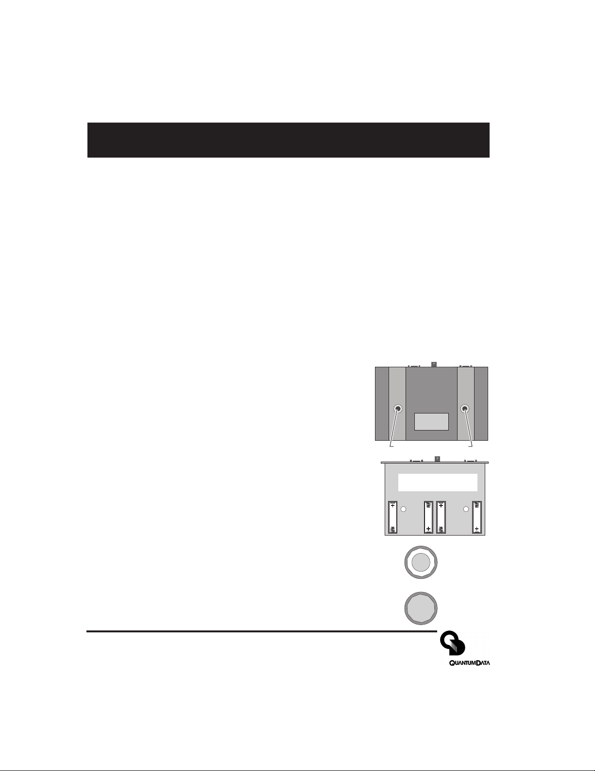
Battery Installation
1) Place the generator face down on a suitable padded surface.
2) Remove the two back cover screws shown in the top figure.
3) Lift the back cover off the generator and locate the four battery
holders as shown in the middle figure.
4) Install the batteries making sure to match up their polarities for
each battery holder. The supplied batteries may not have any
printed polarity indication. The outer metal can is the negative
terminal. The insulated metal button as shown in the end view in the
lower figure is the positive terminal.
Battery locations and
polarity orientation
5) See the information on page 8 to determine if the jumper should be
set to enable user re-calibration of the output levels.
6) Replace the back cover and retaining screws.
7) The supplied batteries may not come fully charged. Connect the supplied
Quantum Data AC power supply and charge the batteries for at least 8
hours.
Low Battery Indication
A “BATTERY LOW” message will blink on the LCD when the NiMH batteries
need recharging or alkaline cells need replacement.
Page 2 Model 606, 607, 608, 609 Quick Start Guide
+
Metal button
surrounded by
insulator
All metal
Making Connections
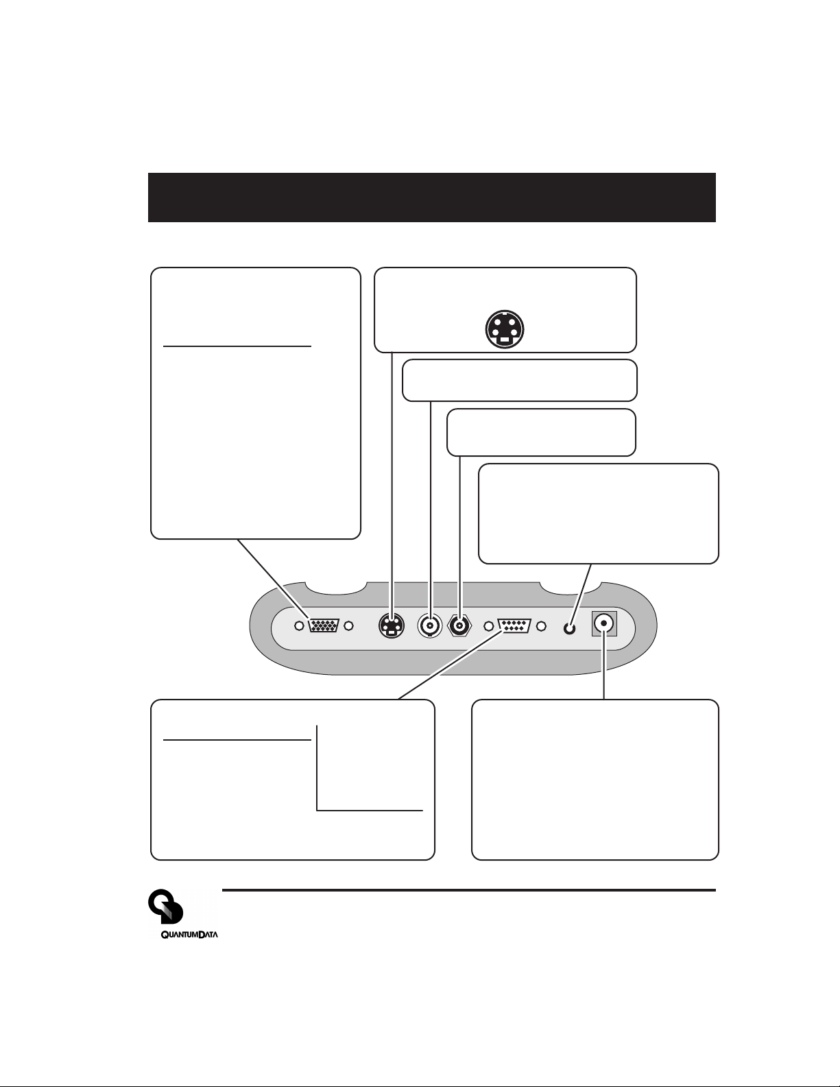
Test Signal Output Connectors
VGA Receptacle
(No HDTV Y,Pr,Pb on 606*)
15 Pin HD D-Sub
Pin # Signal
1 Red Video (*HDTV Pr)
2 Green Video (*HDTV Y)
3 Blue Video (*HDTV Pb)
4 Ground
5 Ground
6 Ground
7 Ground
8 Ground
9 +5 VDC Out
10 Ground
11 Ground
12 DDC Data - SDA
13 TTL Horiz Sync
14 TTL Vert Sync
15 DDC Clock - SCL
VGA/HDTV S VIDEO NTSC/PAL RS 232 AUDIO POWERRF
S-Video Receptacle
4 Pin mini-DIN
Chrominance (C) Luminance (Y)
Ground Ground
(Not on 606)
NTSC / PAL
BNC Receptacle
(Not on 606)
Television RF
F Receptacle
(609 Only)
Stereo Audio - 3.5 mm Phone
(Not on 606 and 607)
Jack
Tip Left Channel (1 KHz)
Ring Right Channel (2 KHz)
Sleeve Ground
RS-232 Port - 9 Pin D-Sub Plug
Pin # Signal
1 No Connection
2 Data In (Rx)
3 Data Out (Tx)
4 DTR Out
5 Ground
6 No Connection
7 RTS Out
8 CTS In
9 No Connection
Factory Defaults:
9600 Baud
8 Data Bits
No Parity
1 Stop Bit
X on - X off
Pinout same as for 9
pin PC-AT serial port
connector
External DC Power /
Battery Recharge Input
Center Pin: +9.0 VDC
Outer Sleeve: - (Ground)
WARNING:
external power source other than the
Quantum Data supplied AC power
supply may cause operator injury
and/or damage the generator.
Attempting to use an
Part 68-00189 Rev I Page 3
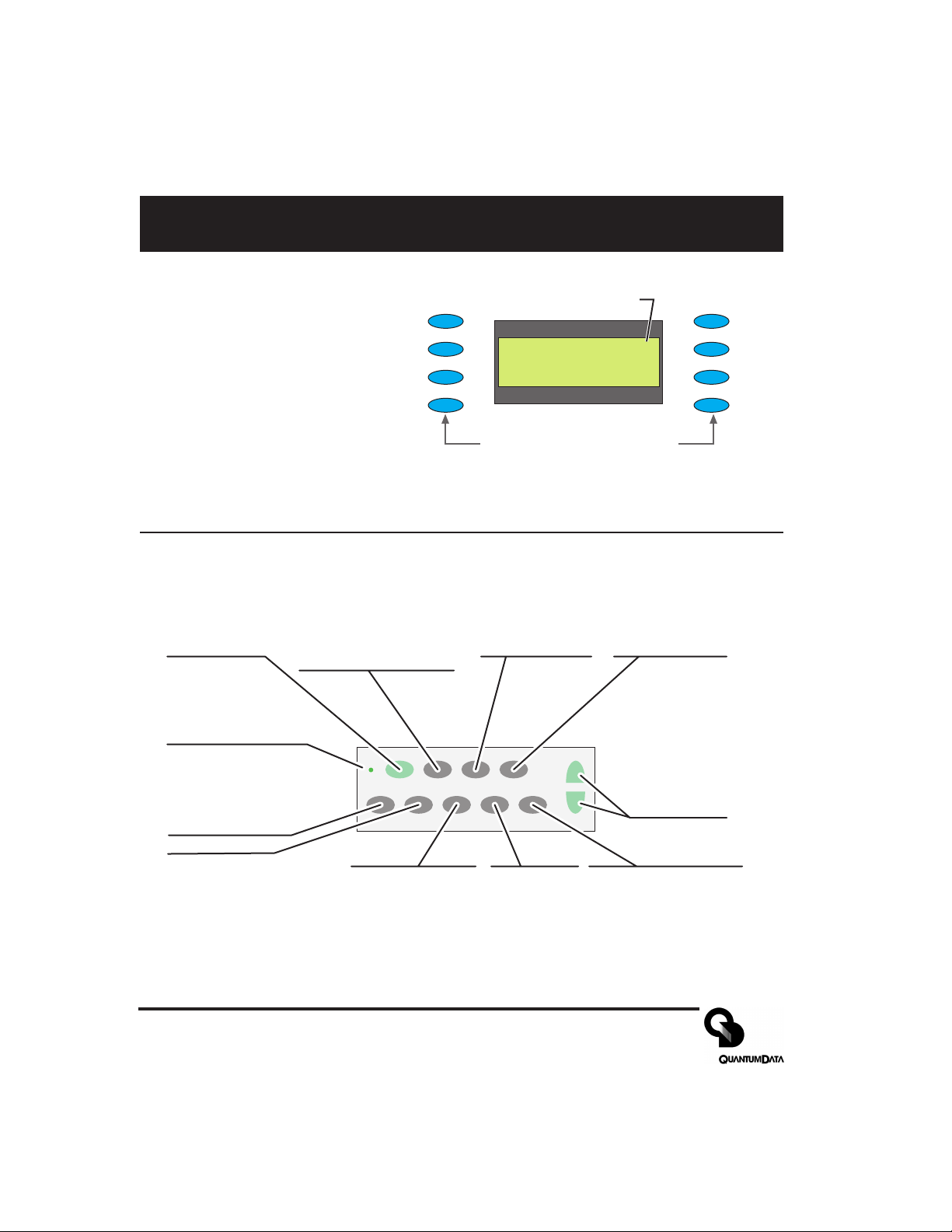
Front Panel Controls and Indicators
LCD Window
The LCD window either
displays messages to the
operator or shows a selection
menu. The figure shows an
example of a selection menu.
Function Buttons
ON/OFF
Toggle generator
power on and off
CHARGE
External power
source (charger)
connected when lit
GATING
Menu for gating video
and sync compontents
on and off
FORMAT
Menu of available video
formats (set-ups) of the
selected signal type.
Item 1
Item 2
Item 3
Item 4
ON/OFF FORMAT IMAGE TEST
CHARGE
SIGNAL
GATING
BACKLIGHT
TYPE
Asterisk indicates active
_ Item_ 1 ______Item_ 5*
_ Item_ 2 ______Item_ 6
_ Item_ 3 ______Item_ 7
_ Item_ 3 ______Item_ 8
Buttons activate items in current
menu list. Use +/ buttons below
to scroll menu screens when
more than 8 items available.
IMAGE
Menu of available
test images.
menu item.
TEST
Menu of available
testing modes.
+ / -
Page through
menu screens
when more
than 8 items
available
OPTIONS
LEARN
MONITOR
Item 5
Item 6
Item 7
Item 8
BACKLIGHT
Toggle LCD backlight on
and off. Goes out 20
seconds after any button
press on batteries. Stays on
when using external power
SIGNAL TYPE
Menu for which
format types are
shown by FORMAT
button
OPTIONS
Menu of
generators
configuration
options.
LEARN MONITOR
Obtain EDID data from
unit under test via DDC
connection.
Page 4 Model 606, 607, 608, 609 Quick Start Guide
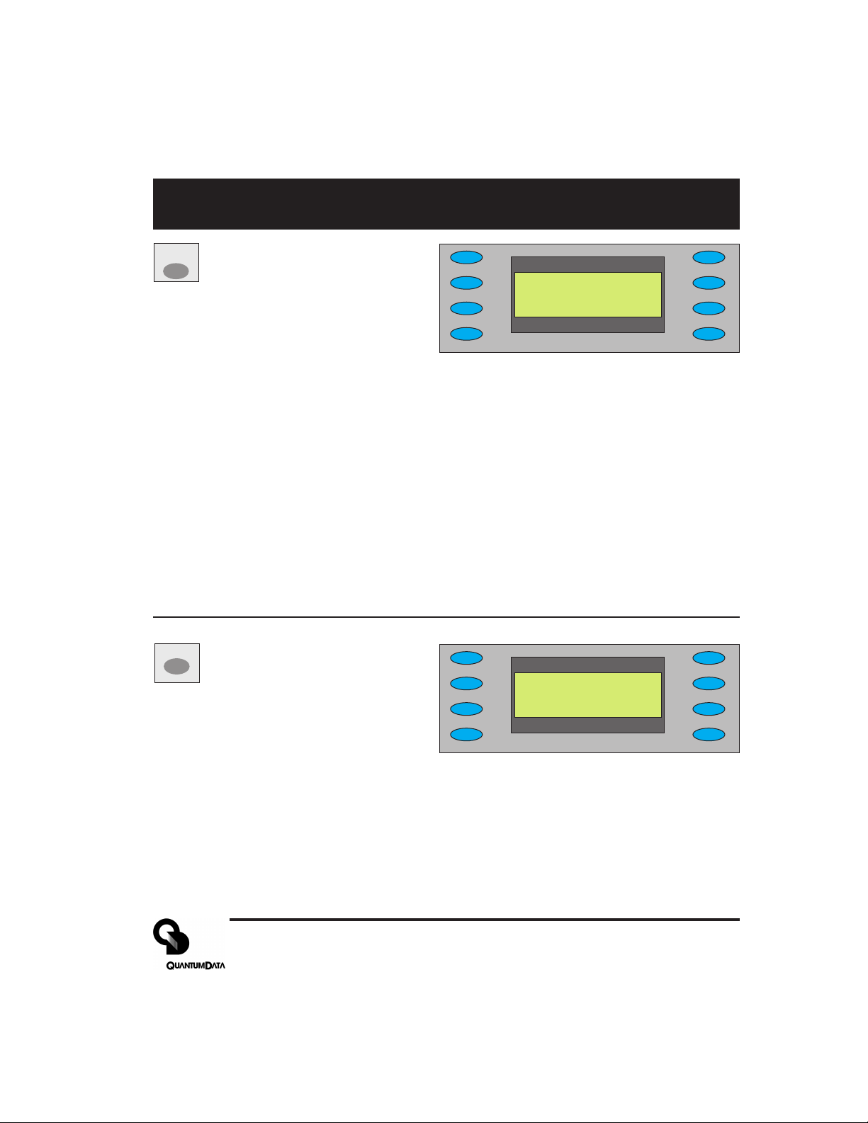
Signal Type and Format Menus
SIGNAL
matching formats. Pressing the FORMAT
Signal Type Menu
TYPE
Selecting one of the video types
shown will display a menu list of
*VESA___________USER
_ NTSC/PAL
_ HDTV_ YPrPb
_ HDTV_ RGB
button will return to the selected menu list
NOTES: VESA = Red, Green, Blue component color video per VESA standards.
(VGA connector used for all output s)
NTSC/P AL = Composite color baseband video signal (BNC connector) and
Separate Luminance and Chrominance video signals (S Video connector) or RGB
component video (VGA connector) per NTSC and PAL standards.
Formats in the Format menu using modulated RF output (Model 609 only) will
have a _Cnn in their name where the nn portion represents the given NTSC-M or
PAL-G television channel used.
HDTV YPrPB = Luminance plus color difference signals per HDTV standards
HDTV RGB = RGB component color video signals per HDTV standards
USER = Section of non-volatile memory reserved for user defined video formats
of any type.
FORMAT
Format Menu
Select from list of video formats
stored in the generator’s memory
of the type selected from the Signal T yp e
*640x480___16001200
_ 800x600___19201440_
_ 1024x768__20481536_
_ 1280x1K___20482048_
menu. Use +/- buttons to page through list
when more than 8 items of a given type are
available. You can use the Quantum Data
VGM software package to add your own formats.You can also edit or replace any of the
factory default formats. A total of 120 video formats can be stored in the generator’s nonvolatile memory. Unused locations are labeled on the LCD as being empty.
The Options menu allows you to remove all formats from all storage locations as well as put
all factory default formats back into their original locations.
Part 68-00189 Rev I Page 5
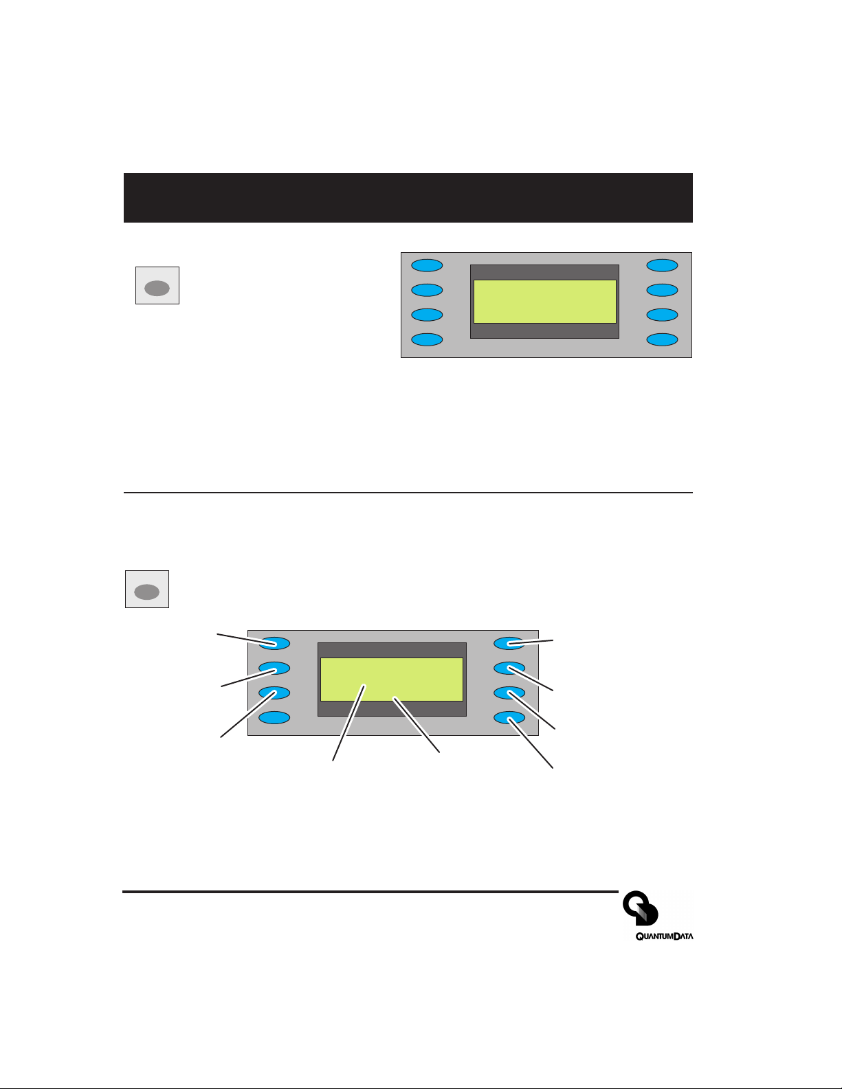
Image and Gating Menu
Image Menu
IMAGE
Select from list of available test
images (patterns). Use +/buttons to page through list if
more than 8 items. The current
firmware does not support adding your own
test images or modifying the built-in ones.
GATING
Gating Menu
Red Color
Component
ON/OFF
Green Color
Component
ON/OFF
Blue Color
Component
ON/OFF
*RED__GATING____ACS_
*GRN____________DCS_
*BLU__Format____DSS*
______Image_____OUT*
Current
Video Format
*Grid_________White
_ Dots___________Red_
_ ColorBar_____Green_
_ GrayBars______Blue
Current
Test Image
ACS - Select Analog
Composite Sync
(Composite Video)
DCS - Select Digital
Composite Sync
DSS - Select Digital
Separate (H&V) Sync
OUT - All test signal
outputs ON/OFF
Page 6 Model 606, 607, 608, 609 Quick Start Guide
 Loading...