

Page 1

Table of Contents
MODEL 606, 607, 608, 609
Video Test Generators
Quick Start Guide
Battery Information and Installation ............................................... 2
Making Connections...................................................................... 3
Front Panel Controls and Indicators.............................................. 4
Selecting Video Formats ............................................................... 5
Selecting Test Images ................................................................... 6
Video and Sync Outputs Gating.................................................... 6
Options Menu................................................................................ 7
Power Save Control ...................................................................... 7
Resetting Formats List to Factory Default ..................................... 7
Outputs Calibration Procedure...................................................... 8
Learning a Monitor’s EDID DDC Data..........................................11
Test Menu.................................................................................... 12
Test Sequence Mode .................................................................. 12
Burn-In Test Mode....................................................................... 13
Horizontal Frequency Shift Test .................................................. 13
DDC Step Mode .......................................................................... 14
Taking CS-1 Color Sensor Measurements.................................. 14
Audio Menu ................................................................................. 15
Installing New Firmware .............................................................. 15
VGM Software Overview and Basic Operation ........................... 16
Creating Formats Using VGM Software ...................................... 17
Creating Sequences Using VGM Software ................................. 18
Specifications Summary.............................................................. 19
Service and Support Locations ................................................... 20
Declaration of Conformity............................................................ 20
Part 68-00189 Rev I Page 1
Page 2
Preparation for first time use
Back Cover Screws
Battery Types Used
The Model 606, 607, 608 and 609 generators come with four (4) size AA rechargeable Nickel Metal
Hydride (NiMH) batteries. These 1500 mA-H rated batteries can normally be recharged about 1000
times before needing replacement. Only suitable NiMH batteries can be safely recharged in the
generator.
You can use alkaline AA batteries with the generator provided that you never use an external power
supply with the generator while the alkaline cells are in the unit. Attempting to operate the generator
or recharge alkaline cells with the external power supply may cause operator injury and/or
damage the generator! Never mix battery types in the generator.
AC Power Supply
The AC power supply that comes with the generator has an input voltage range of 100-240 VAC from
47 to 63 Hz. The output is rated at 9.0 VDC @ 1.67 Amp. This is sufficient to operate the generator and
recharge the batteries at the same time. Attempting to operate the generator or recharge the
batteries with any other type of external power supply may cause operator injury and/or damage
to the generator!
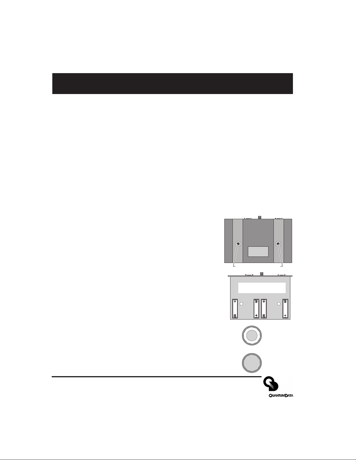
Battery Installation
1) Place the generator face down on a suitable padded surface.
2) Remove the two back cover screws shown in the top figure.
3) Lift the back cover off the generator and locate the four battery
holders as shown in the middle figure.
4) Install the batteries making sure to match up their polarities for
each battery holder. The supplied batteries may not have any
printed polarity indication. The outer metal can is the negative
terminal. The insulated metal button as shown in the end view in the
lower figure is the positive terminal.
Battery locations and
polarity orientation
5) See the information on page 8 to determine if the jumper should be
set to enable user re-calibration of the output levels.
6) Replace the back cover and retaining screws.
7) The supplied batteries may not come fully charged. Connect the supplied
Quantum Data AC power supply and charge the batteries for at least 8
hours.
Low Battery Indication
A “BATTERY LOW” message will blink on the LCD when the NiMH batteries
need recharging or alkaline cells need replacement.
Page 2 Model 606, 607, 608, 609 Quick Start Guide
+
Metal button
surrounded by
insulator
All metal
Page 3
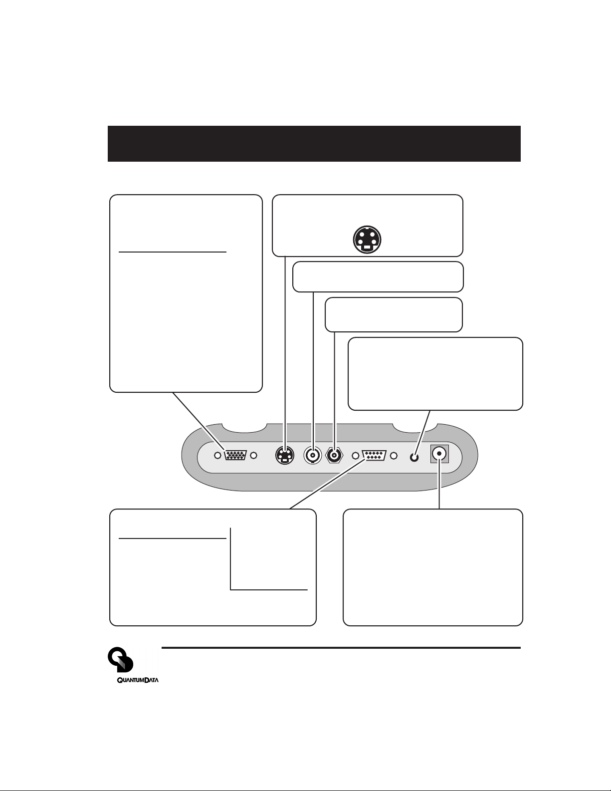
Making Connections
Test Signal Output Connectors
VGA Receptacle
(No HDTV Y,Pr,Pb on 606*)
15 Pin HD D-Sub
Pin # Signal
1 Red Video (*HDTV Pr)
2 Green Video (*HDTV Y)
3 Blue Video (*HDTV Pb)
4 Ground
5 Ground
6 Ground
7 Ground
8 Ground
9 +5 VDC Out
10 Ground
11 Ground
12 DDC Data - SDA
13 TTL Horiz Sync
14 TTL Vert Sync
15 DDC Clock - SCL
VGA/HDTV S VIDEO NTSC/PAL RS 232 AUDIO POWERRF
S-Video Receptacle
4 Pin mini-DIN
Chrominance (C) Luminance (Y)
Ground Ground
(Not on 606)
NTSC / PAL
BNC Receptacle
(Not on 606)
Television RF
F Receptacle
(609 Only)
Stereo Audio - 3.5 mm Phone
(Not on 606 and 607)
Jack
Tip Left Channel (1 KHz)
Ring Right Channel (2 KHz)
Sleeve Ground
RS-232 Port - 9 Pin D-Sub Plug
Pin # Signal
1 No Connection
2 Data In (Rx)
3 Data Out (Tx)
4 DTR Out
5 Ground
6 No Connection
7 RTS Out
8 CTS In
9 No Connection
Factory Defaults:
9600 Baud
8 Data Bits
No Parity
1 Stop Bit
X on - X off
Pinout same as for 9
pin PC-AT serial port
connector
External DC Power /
Battery Recharge Input
Center Pin: +9.0 VDC
Outer Sleeve: - (Ground)
WARNING:
external power source other than the
Quantum Data supplied AC power
supply may cause operator injury
and/or damage the generator.
Attempting to use an
Part 68-00189 Rev I Page 3
Page 4
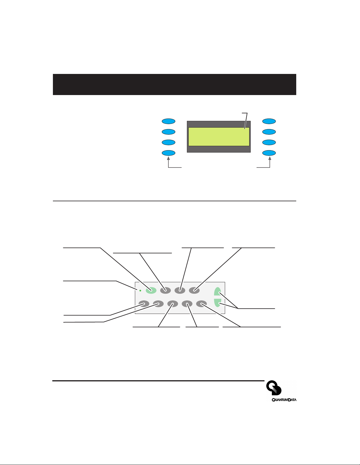
Front Panel Controls and Indicators
LCD Window
The LCD window either
displays messages to the
operator or shows a selection
menu. The figure shows an
example of a selection menu.
Function Buttons
ON/OFF
Toggle generator
power on and off
CHARGE
External power
source (charger)
connected when lit
GATING
Menu for gating video
and sync compontents
on and off
FORMAT
Menu of available video
formats (set-ups) of the
selected signal type.
Item 1
Item 2
Item 3
Item 4
ON/OFF FORMAT IMAGE TEST
CHARGE
SIGNAL
GATING
BACKLIGHT
TYPE
Asterisk indicates active
_ Item_ 1 ______Item_ 5*
_ Item_ 2 ______Item_ 6
_ Item_ 3 ______Item_ 7
_ Item_ 3 ______Item_ 8
Buttons activate items in current
menu list. Use +/ buttons below
to scroll menu screens when
more than 8 items available.
IMAGE
Menu of available
test images.
menu item.
TEST
Menu of available
testing modes.
+ / -
Page through
menu screens
when more
than 8 items
available
OPTIONS
LEARN
MONITOR
Item 5
Item 6
Item 7
Item 8
BACKLIGHT
Toggle LCD backlight on
and off. Goes out 20
seconds after any button
press on batteries. Stays on
when using external power
SIGNAL TYPE
Menu for which
format types are
shown by FORMAT
button
OPTIONS
Menu of
generators
configuration
options.
LEARN MONITOR
Obtain EDID data from
unit under test via DDC
connection.
Page 4 Model 606, 607, 608, 609 Quick Start Guide
Page 5
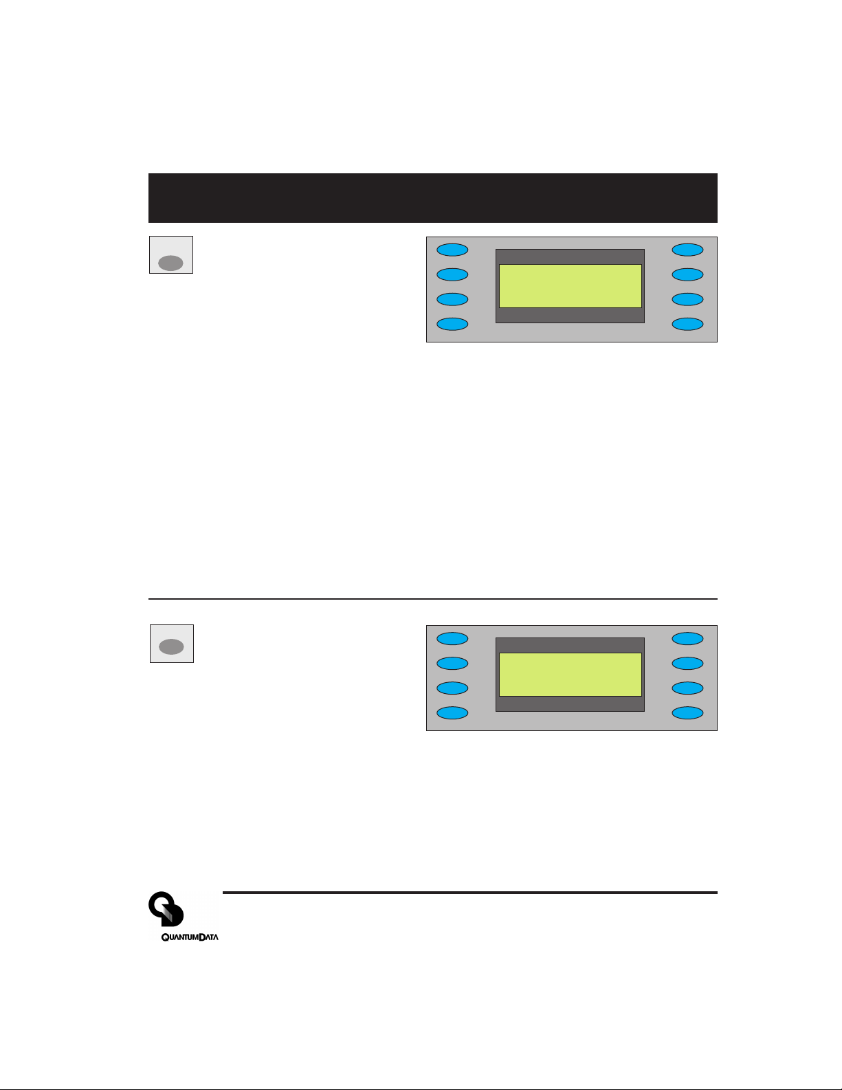
Signal Type and Format Menus
SIGNAL
matching formats. Pressing the FORMAT
Signal Type Menu
TYPE
Selecting one of the video types
shown will display a menu list of
*VESA___________USER
_ NTSC/PAL
_ HDTV_ YPrPb
_ HDTV_ RGB
button will return to the selected menu list
NOTES: VESA = Red, Green, Blue component color video per VESA standards.
(VGA connector used for all output s)
NTSC/P AL = Composite color baseband video signal (BNC connector) and
Separate Luminance and Chrominance video signals (S Video connector) or RGB
component video (VGA connector) per NTSC and PAL standards.
Formats in the Format menu using modulated RF output (Model 609 only) will
have a _Cnn in their name where the nn portion represents the given NTSC-M or
PAL-G television channel used.
HDTV YPrPB = Luminance plus color difference signals per HDTV standards
HDTV RGB = RGB component color video signals per HDTV standards
USER = Section of non-volatile memory reserved for user defined video formats
of any type.
FORMAT
Format Menu
Select from list of video formats
stored in the generator’s memory
of the type selected from the Signal T yp e
*640x480___16001200
_ 800x600___19201440_
_ 1024x768__20481536_
_ 1280x1K___20482048_
menu. Use +/- buttons to page through list
when more than 8 items of a given type are
available. You can use the Quantum Data
VGM software package to add your own formats.You can also edit or replace any of the
factory default formats. A total of 120 video formats can be stored in the generator’s nonvolatile memory. Unused locations are labeled on the LCD as being empty.
The Options menu allows you to remove all formats from all storage locations as well as put
all factory default formats back into their original locations.
Part 68-00189 Rev I Page 5
Page 6
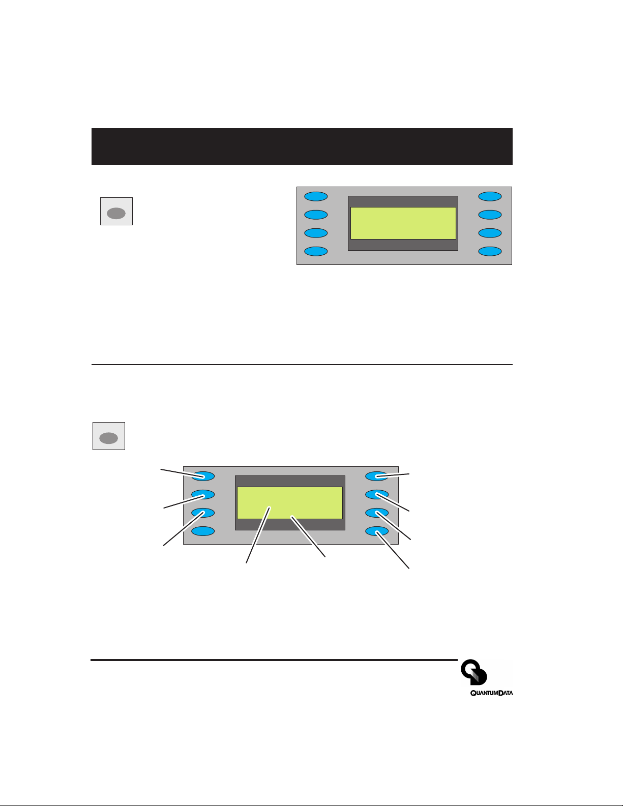
Image and Gating Menu
Image Menu
IMAGE
Select from list of available test
images (patterns). Use +/buttons to page through list if
more than 8 items. The current
firmware does not support adding your own
test images or modifying the built-in ones.
GATING
Gating Menu
Red Color
Component
ON/OFF
Green Color
Component
ON/OFF
Blue Color
Component
ON/OFF
*RED__GATING____ACS_
*GRN____________DCS_
*BLU__Format____DSS*
______Image_____OUT*
Current
Video Format
*Grid_________White
_ Dots___________Red_
_ ColorBar_____Green_
_ GrayBars______Blue
Current
Test Image
ACS - Select Analog
Composite Sync
(Composite Video)
DCS - Select Digital
Composite Sync
DSS - Select Digital
Separate (H&V) Sync
OUT - All test signal
outputs ON/OFF
Page 6 Model 606, 607, 608, 609 Quick Start Guide
Page 7

Options Menu - Clear Formats, Reload Formats
OPTIONS
Options Menu
This menu is used for system level options.
Power Save - Toggles enabling and disabling Power Saver option.
Calibrate - Displays calibration Menu
for setting RGB analog video and
Pwr Save:On
NTSC_Cal___Calibrate
Clr_ Fmts__ReloadFmts
NTSC_Cal - (Not on Model 606) Displays calibration Menu for setting peak white
signal on the TV output BNC connector. Appears only if the generator has been
configured to allow recalibration (see page 8).
Clr Fmts - Clears all formats from user memory.
sync amplitudes. Appears only if the
generator has been configured to
allow recalibration (see page 8).
Reload Fmts - Restores all factory
deafult formats without deleteing user
defined formats
Options Menu - Pwr_Save Button (added in version 2.02 firmware)
When On and running from batteries: Unit will shut down after 30 minutes of no front panel
activity and the unit is not running in Burn-in test mode.
When On and running from external power: Current units ignore 30 minute shutdown timer
Older units updated to current firmware will shut down after 30 minutes of no front panel
activity and the unit is not in Burn-in test mode.
When Off: Unit ignores 30 minute shutdown timer and will continue to operate from either an
external power source or until the internal batteries are discharged.
Options Menu - Clr Fmts and Reload Fmts Buttons
Pressing the Clr Fmts button displays a confirmation request menu to clear all formats in
memory. Selecting Yes will cause all video formats in memory to be lost. There is no
way to abort or undo this operation. The LCD window will show “Initializing EEROM” when
the process is completed. Pressing the FORMA T button will display the Formats menu to list
the restored memory contents.
Pressing the Reload Fmts button restores all factory default formats to their original memory
locations. Any user formats in those locations will be lost. User format s saved in other memory
locations are left alone. The LCD will show Reloaded when the process is completed.
Part 68-00189 Rev I Page 7
Page 8

Options Menu - Output Calibration
U22
J5
Pin #1
All Model 606, 607 and 608 video test generators use programmable hardware to set all of the amplitude calibration factors analog video outputs. These calibration factors are stored in Flash EPROM and
are not lost if the batteries are run down or removed. Firmware updates will not affect these factors in
most cases. A hardware jumper inside the unit enables user modification of the settings.
All generators leave our factory with the analog video and sync output amplitudes calibrated to published specifications. You can recalibrate these amplitudes over a nominal range to meet your specific
testing conditions.
WARNING: There is no way to recall any of the original factory calibration settings once
you have
to nominal overwrites all previously saved factory or user settings.
Equipment needed
DC voltmeter capable of measuring from 0 to 1 volt with a minimum resolution of 2 millivolts
Precision 75 ohm (+/- 1%) input terminator for the meter
Test cable to connect the voltmeter to the R, G, B and Ground pins on the VGA connector.
Additional Equipment for Model 608 NTSC Output Re-calibration:
Oscilloscope with a precision 75 ohm (+/- 1%) input impedance and suitable gain and bandwidth to
display a 1.00 Volt pk-pk signal with 3.579 MHz color carrier
One 75 ohm coaxial cable to connect the oscilloscope to the BNC TV output.
saved any of your own settings. Saving your calibration settings or resetting
Enabling user re-calibration
All generators leave our factory with an internal hardware jumper set to disable user modification of the
calibration settings. You can check the current jumper setting by turning on the generator and pressing
the OPTIONS button. If “Calibrate” is one of the menu choices, the jumper is set to enable re-calibration. The following steps describe changing the jumper setting if the menu choice does not appear.
1) Turn off the generator and follow the directions on page 2 for remov-
ing the back cover.
2) Locate J5 as shown in the figure on the right.
3) The generator leaves our factory with a removable shorting jumper
on pin 1 or pin 2. You will need to provide a suitable shorting jumper
to enable user calibration if the original jumper is missing.
4) Place the jumper so it connects pin 1 to pin 2. Placing the jumper so
that it only connects to pin 1
5) You can replace the back cover but do not need to screw it down if you intend to reset the jumper
after performing the re-calibration. You can replace the screws if you intend to leave the jumper as
is. The re-calibration procedure does
Page 8 Model 606, 607, 608, 609 Quick Start Guide
or pin 2 will disable user calibration.
not require access to any test points inside the case.
Page 9

_____Calibrate
_ Black________Blank
_ Full_ Scale____Zero
_ Reset______BP_ Sync
_ R_FS+________-R_FS
_ G_FS+________-G_FS
_ B_FS+________-B_FS
_ Save__________Back
_ R_Zero+____-R_Zero
_ G_Zero+____-G_Zero
_ B_Zero+____-B_Zero
_ Save__________Back
Options Menu - Output Calibration Continued
Setting calibration factors to nominal values
The Reset selection in the main calibration menu (top figure on right) sets
all of the generator’s calibration factors to default nominal values. You
need to select “Yes” in the following confirmation menu to reset.
Nominal values are not the same as the factory set values for a given
unit. This operation overwrites any previously saved calibration
factors and can not be undone.
Calibration Procedure
1) Make sure the generator is running with fully charged batteries or
from the external AC power supply.
2) Press the OPTIONS button and select Calibrate. See the previous
section, Enabling user-calibration, if the selection is not listed.
3) You will get the menu shown in the first figure on the right. Select Full
Scale to get the menu shown in the second figure.
4) Make sure that the DC Volt meter has a 75 ohm (+/- 1%) input
termination in place. This termination is required for all calibration steps. The negative lead of the
meter connects to any ground pin (4, 5, 6, 7, 8, 10 or 11) on the VGA connector for all steps.
5) Set the meter’s scale factor to be able to measure a nominal 1000 millivolts DC and connect the
positive input to the generator’s red output (pin #1 of VGA connector).
6) Use the R_FS+ and -R_FS menu buttons to set the DC output level to 1000 mV +/- 3 mV.
7) Move the meter input to the generator’s blue output (pin #3 of VGA connector) and use the B_FS+
and -B_FS menu buttons to set the DC output level to 1000 mV +/- 3 mV.
8) Move the meter input to the generator’s green output (pin #2 of VGA connector) and use the
G_FS+ and -G_FS menu buttons to set the DC level to 1000 mV +/- 3 mV.
9) Press Save and then the Back menu button to return to the previous menu.
10) Select Zero to get the menu shown in the third figure.
11) Move the meter input to the generator’s red output and use the R_Zero+ and -R_Zero menu
buttons to set the DC output level to 0 mV +/- 3 mV.
12) Move the meter input to the generator’s blue output and use the B_Zero+ and -B_Zero menu
buttons to set the DC output level to 0 mV +/- 3 mV.
13) Move the meter input to the generator’s green output and use the G_Zero+ and -G_Zero menu
buttons to set the DC level to 1000 mV +/- 3 mV.
14) Press Save and then the Back menu button to return to the previous menu.
15) Select Blank and then use the Blank+ and -Blank menu buttons to set the DC level for the green
output to 286 mV +/- 3 mV. Press Save then Back menu buttons to return to the previous menu.
Part 68-00189 Rev I Page 9
Page 10

Options Menu - Output Calibration Continued
_ R_NTSC+____-R_NTSC
_ G_NTSC+____-G_NTSC
_ B_NTSC+____-B_NTSC
_ Save__________Back
16) Select Black and then use the Black+ and -Black menu buttons to set the DC level for the green
output to 340 mV +/- 3 mV. Press Save and then the Back menu button to return to the previous
menu.
This completes the calibration adjustments for a Model 606 generator.
17)
Skip steps 18 through 28 for the Model 606 and continue with step 29.
18) Select BP_Sync and then use the BP_Sync+ and -BP_Sync menu buttons to set the DC level to
600 mV +/- 3 mV. Press Save and then the Back menu button to return to the previous menu.
This completes the calibration adjustments for a Model 607 generator.
19)
Skip steps 20 through 28 for the Model 606 and continue with step 29.
20) Disconnect the DC voltmeter from the generator and connect an oscilloscope to the NTSC/PAL
connector on the generator using a suitable 75 ohm coaxial cable. Make sure that oscilloscope has
a 75 ohm input impedance or that you have a suitable 75 ohm terminator attached if it has a high
impedance input.
21) Press the OPTIONS button and select NTSC_CAL. Y ou will get the
menu shown on the right.
22) Adjust the oscilloscope’s timebase and sweep trigger to view one
stable horizontal scan line of video. Adjust the oscilloscope’s gain
and vertical positioning so that you can see both the blanking and
peak (white) video levels. The sync tips do not need to be displayed.
23) Adjust the Red, Green and Blue calibration factors to get minimum pk-pk color sub-carrier
modulation of the white level. If the modulation increases, you are adjusting in the wrong direction.
First adjust Green, then Red and then Blue.
24) Increase or decrease Red and Green by equal amounts to set the average white video level to 714
mV (+/- 5 mV) above Blanking.
25) Adjust Blue for minimum modulation.
26) Individually adjust Red and Green to get a 714 mV (+/- 5 mV) average white level with minimum
sub-carrier modulation.
27) Adjust Blue for minimum modulation.
28) Repeat steps 26 and 27 until the average white level is 714 mV (+/- 5 mV) and sub-carrier modulation can not be reduced any further.
Note: The modulated RF output on the Model 609 does not have any calibration settings.
29) Remove the shorting jumper between pins 1 and 2 on J5 if you wish to prevent someone from
changing the calibration settings. The jumper can be positioned to just attach to pin 1 or pin 2 in
this case.
30) Make sure the rear cover is fastened back in place as described on page 2.
Page 10 Model 606, 607, 608, 609 Quick Start Guide
Page 11

Learn Monitor Function (DDC/EDID Data)
LEARN
MONITOR
connected to the generator’s VGA output. A
Learn Monitor
Reads back EDID data from a
VESA® DDC compliant display
_______Reading
_______Monitor
_______Complete
Details
list of standard VESA video formats supported by the monitor is extracted from the
EDID data and compared against all of the
VESA format s in the generator’s built in
library . A table is then built of all the matching formats. This table can be viewed by
pressing the EDID Detail menu button. This
Show details of EDID
after successful read
back from display
under test
Complete indicates EDID
data was read back
correctly.
Failed indicates unable to
read back valid EDID data
table of formats is used for the DDC Step
Test function.
EDID Detail
Lists all of the matching VESA standard video formats from the last successful Learn Monitor
operation. The list is left as is if the operation fails. The +/– buttons can be used to page
through the list if there are more than eight (8) learned formats. You can not select the formats
using the menu buttons. However, you can go through all the format s using the DDC Step
Test function.
NOTE: It is possible that the display’s EDID data will include non-VESA formats. These nonstandard formats will not be listed.
Part 68-00189 Rev I Page 11
Page 12

Test Menu and Sequence Mode Sub-menu
TEST
Test Menu
Select special test operating modes.
Sequence Mode
Sub-Menu
Burn-In Mode
Sub-Menu
Freq Shift Mode
Sub-Menu
Audio Set-up
Sub-Menu
_ Sequence______Probe
_ Burn-In____DDC_ Step
_ FreqShift
_ Audio
Probe
CS-1 Readings
Sub-Menu
DDC Step
Mode
Sub-Menu
TEST
+
Sequence
Sequence Mode
Uses +/- buttons to manually step through a sequence of defined tests. Each step
loads a given video format and test image. Menu buttons permit the operator to
gate video color information, change sync types and turn all signal outputs on and
off. The current firmware includes a sample test sequence. You can use Quantum Dat a’s
VGM software to create and save your own test sequence. Use the Burn-in Test menu selection if you wish for the generator to automatically cycle through all of the steps.
ASC - Select Composite
Red Color
Component
ON/OFF
Green Color
Component
ON/OFF
Blue Color
Component
ON/OFF
_ Red__SEQ_ NAME__ACS
_ Grn__Step#xxx__DCS
_ Blu___Format___DSS*
_______Image____OUT*
Line 1: Name of Test Sequence currently running.
Line 2: Current step number in sequence
Line 3: Video format used in current step
Line 4: Test image used in current step
Analog Sync
(Composite Video)
DCS - Select Digital
Composite Sync
DSS - Select Digital
Separate (H&V) Sync
OUT - All test signal
outputs ON/OFF
Page 12 Model 606, 607, 608, 609 Quick Start Guide
Page 13

Burn-in Mode, and Frequency Shift Sub-menus
TEST
+
Burn-In
Burn-in Mode
Uses Run/Stop menu button to have the generator automatically and continuously cycle through a sequence of defined tests. Each step loads a given video
format and test image. Menu buttons permit operator to gate video color information, change sync types and turn all signal outputs on and off. The current firmware includes a
sample burn-in sequence. Future versions of generator firmware and Quantum Data’s VGM
software may permit user defined burn-in sequences to be created and downloaded into the
generator .
Run - Press to run
Burn-in.
Stop - Press to stop
Red Color
Component
ON/OFF
Green Color
Component ON/OFF
Blue Color
Component ON/OFF
_ Run___Burn-In__OUT*
_ Red___step#1___DSS*
_ Grn___800_@60__DCS_
_ Blu___Focus____ASC
Line 1: Name of Burn-in test currently running.
Line 2: Current step number in cycle
Line 3: Video format used in current step
Line 4: Test image used in current step
OUT - All test signal
outputs ON/OFF
DSS - Select Digital
Separate (H&V) Sync
DCS - Select Digital
Composite Sync
ASC - Select
Composite Analog
Sync (Composite
Video)
NOTE: The 30 minute Power-Save T imer is ignored when running in Burn-in mode. The unit
will continue to operate until the battery charge is exhausted if running from internal batteries.
TEST
+
FreqShift
Freq Shift Mode
Uses +/- buttons to increase
and decrease the horizontal
scanning frequency of the
_____Freq. Shift
-10%_ -----+-----_ +10
__________^
__H= +31.469E+03
current video format +/- 10% in 2% increments. The ^ pointer indicates the percent
deviation and the bottom number shows the
actual frequency .
Part 68-00189 Rev I Page 13
Page 14

DDC Step and Probe Mode Sub-menus
TEST
+
DDC Step
DDC Step Mode
Uses + button to step through video formats in list produced by Learn DDC
function. Uses - button to step through all available test images. Pressing Run
menu button causes generator to automatically cycle through all test images for
every video format in the list. Pressing Stop menu button restores manual stepping.
Run - Press to run
Automatcally cycle
through all format and
test images
Stop - Press to return to
manual format and
image stepping
Red Color Component
ON/OFF
Green Color
Component ON/OFF
Blue Color Component
ON/OFF
TEST
CS-1 Probe Test Mode
_ Run__DDC_ Step__OUT*
_ Red____________DSS*
_ Grn___Format___DCS_
_ Blu___Image____ASC
Line 1: Video format used in current step
Line 2: Test image used in current step
OUT - All test
signal outputs
ON/OFF
DSS - Select
Digital Separate
(H&V) Sync
DCS - Select
Digital Composite
Sync
ASC - Select
Composite Analog
Sync (Composite
Video)
Uses the Quantum Data Model CS-1 color sensor to measure the chromaticity
+
CS1 Probe
and luminance (brightness) of the test CRT display. The CS-1 probe connects
directly to the serial port on the generator . Chromaticity is shown as x,y C.I.E.
coordinates and the luminance (Y) can be shown either in units of foot-Lamberts or nits. The
CS-1 needs to be over a fully lit white area of the CRT screen for accurate readings. The builtin Flat_Wht test image is suitable for use with the CS-1
fL/nits - Toggle
between footLamberts and
nits for units of
measure and
take new reading.
Read - Take new
reading.
______Y:_ 24.141_ fL
______x:_ .293
______y:_ .279
_ Read_______fL/nits
Error Codes: 1, 7 - CS-1 not seeing a usable test image.
5, 8 - Generator did not find a Model CS-1 probe.
2, 3, 6 - Probe malfunctioning.
Page 14 Model 606, 607, 608, 609 Quick Start Guide
Page 15

Audio Mode Sub-menu and Installing Firmware
Audio Menu
TEST
Audio menu buttons independently toggle stereo audio output
+
Audio
channels on and off
(Models 608 and 609 only).
Left channel is also as the monophonic
audio source for the modulated RF output on the Model 609.
Installing New Generator Firmware
The generator’s operating system firmware is stored in Flash EPROM that can be updated via
the serial port
Firmware updates are available from http://www.quantumdat a.com/support/downloads/.
To install a firmware update:
1. With the generator turned off, connect it to the PC using a suitable null modem serial cable.
2. Hold down the upper left menu button on the generator and press the POWER button for about
one second and then release both buttons. The LCD screen will indicate the unit is ready for the
upload. (NOTE: Remove batteries and external power if you need to cancel the upload)
3. Expand the .zip archive file that contains the firmware update.
4. If you have HyperTerminal, double-click the HyperTerminal setup file (QD60x Upgrade.ht) to start
HyperTerminal with the proper communications setup. (If you are using a Com port other than
Com 1, in HyperTerminal choose File > Properties to select the desired Com port.)
If you are using a terminal communications program other than HyperTerminal, set your communications parameters to 9600 bps, 8 data bits, 1 stop bit, no parity, software handshaking (Xon /
Xoff), and ANSI terminal emulation.
5. In HyperTerminal, select Transfer > Send Text File.
6. In the Send Text File dialog box, double-click the firmware filename to start the transfer.
The generator will display the progress of the update and then go through a power up cycle at the
completion of the update. The model number and firmware revision number will be on the LCD.
7. Press the OPTIONS button on the generator and then select "Clear Fmts" from the menu. When
asked to confirm clearing the formats memory, press the Yes button.
8. After all locations are cleared, press the Options button, and then select Reload Fmts. This will
load the nonvolatile memory with the new firmware’s factory default formats.
L _ Audio On
R _ Audio Off
Part 68-00189 Rev I Page 15
Page 16

Operating with VGM Software
Current Capabilities
The current firmware in the Model 606, 607 and 608 generators allows you add and delete
video formats and test sequences that are stored in the generator’s non-volatile memory.
About 120 formats and one test sequence can be stored with the current firmware. The
easiest way to create and edit formats and sequences is to use Version 3.00 of Quantum
Data’s Video Generator Manager (VGM). The current release of VGM was originally created
for use with our Model 801, 802 and 822 video generators. It has limited support for the Model
600 series. You can download, edit and upload video formats and sequences using the current
releases of firmware and VGM 3.00. VGM 3.00 runs under MS-Windows 95, 98 and recent
versions of NT.
Please refer to the VGM 3.00 help file for additional information on performing specific steps.
Connecting to the Generator
1) Connect the generator to the computer using a suitable RS-232 cable.
2) Install the VGM software if you have not all ready done so and start VGM.
3) Click the Connect button on the main VGM screen and then choose the correct
serial port connection from the port selection dialog box. VGM will attempt a connection at
the Model 800 series default rate of 2400 Baud and then scan through the rates until it
finds the Model 600 series’ 9600 Baud rate.
4) The generator will now be listed in the connections pane of the Main VGM screen. Double
click on the Generator’s entry in that pane.
5) VGM will scan the contents of the generator for lists of available formats and test images
and then open a Generator screen.
Page 16 Model 606, 607, 608, 609 Quick Start Guide
Page 17

Programming Video Formats with VGM Software
Selecting a Format to Edit
1) You can either choose to start with a default format in the VGM format editor or choose
any of the formats available in the generator . Refer to the VGM help file for information on
using the VGM’s default format.
2) If you want to edit one of the formats available in the generator, you start from the list of
available formats. The instruction on the previous page tell you how to get to this point.
3) Select the format you wish to edit by single clicking its name in the list. Click the
Load Data button to load the format into the Main VGM screen’s buffer p ane.
4) Double click on the format in the buffer pane. This will start the format editor using the
selected format’s information.
Using the Format Editor
The format editor works as described in the VGM help file except that the physical size
entries have no affect on how test images are displayed on the Model 600 series. However, the integer portion of the horizont al size in millimeters is used to identify the storage
location of the format in the generator. Unlike our other models, the generators in the 600
series store formats by specific numeric locations and not by name. If you do not change
this number, the edited format will replace the previous version of the format when you
upload it back to the generator. You will not get any warnings that you are about to overwrite a memory location.
Saving a Format and Uploading it to the Generator
1) You need to save your edited format to disk before you can upload it to the generator .
Select File > Save A s from editor menu bar and select a suitable name and storage
location.
2) Select the edited format in the Main VGM buffer pane and select the generator in the
connections pane.
3) Click the Send Data button to upload the selected format to the selected generator.
The format will be stored using the numbered storage location set in the editor .
4) You will need to disconnect from the generator, power cycle the generator, and reconnect
in order for the added format to appear in the list of available formats.
Part 68-00189 Rev I Page 17
Page 18

Programming Test Sequences with VGM Software
Selecting a Sequence to Edit
1) You can choose to start with a blank default sequence in the VGM Sequence editor, the
sequence currently saved in the generator or a previously created sequence saved on
disk. Refer to the VGM help file for information on using the VGM’s default sequence or
sequence saved on disk.
2) If you want to edit the sequence saved in the generator, start by clicking the Sequence List Button on the VGM Generator screen.
3) Select the Sequence (there is only one) by single clicking its name in the list. Click the
Load Data button to load the Sequence into the Main VGM screen’s buf fer p ane.
4) Double click on the Sequence name in the buffer pane. This will start the Sequence editor
using the selected Sequence’s information.
Using the Sequence Editor
The basic operation of the Sequence editor is as described in the VGM help file except
that the current generator firmware only supports selecting a format and test image for
each step. Any output gating or sync selections made for a given step will be ignored by
the generator. You must also explicitly name a format and image for each step. Unexpected formats and images may load if you leave either the format or image selection as
“No Change” from the previous step. Also, you can not test or play the Sequence with
VGM. The Sequence will only work using the generator’s front panel buttons.
Saving a Sequence and Uploading it to the Generator
1) You need to save your edited Sequence to disk before you can upload it to the generator .
Select File > Save A s from editor menu bar and select a suitable name and storage
location.
2) Select the edited Sequence in the Main VGM buffer pane and select the generator in the
connections pane.
3) Click the Send Data button to upload the selected Sequence to the selected generator, overwriting the previously stored Sequence. Only one Sequence can be stored in the
generator at any given time. You will get a warning if you start to save a Sequence using
the same name as the currently stored Sequence.
Page 18 Model 606, 607, 608, 609 Quick Start Guide
Page 19

Specifications Summary
Video Formats:
Storage: 100 Total
Built-in: VESA Standards
Edit Method: Quantum Data’s MS-Windows
NTSC (607, 608, 609)
PAL (607, 608, 609)
HDTV (608, 609)
based VGM software
Test Patterns (Images)
Blank Raster, Flat White, Flat Red, Flat
Green, Flat Blue, Grid, Grids, Overscan,
Cutoff, Window, Focus, Color Bar, Gray Bar,
HV Regulation, Dots, SMPTE Bar, Ramp,
Burst, Pulse Bar
Horizontal Timing
Frequency: 1 KHz to 250 KHz
Total Pixels: 144 to 4096
Active Range: 16 to 4096 pixels
Vertical Timing
Frequency: 1 Hz to 650 Hz
Active Lines: 1 to 4096
Scan Types: Progressive, 2:1 Interlace
Sync Types
Separate Digital Horizontal and Vertical
Digital and Analog Composite
Bipolar HDTV (608, 609)
Video Outputs
Timing Accuracy: 2%
Connectors: See diagram on page 3.
RF Output (Not all Models)
Channels: UHF channels with
Video: Color per NTSC (M) and PAL
Audio: Mono 1 KHz Tone per NTSC
Connector: Female F type
frequencies per NTSC (M)
and PAL (G). Specific channel
usage/availability determined
by current firmware.
(G)
(M) and PAL (G)
Audio Outputs (Not all Models)
Connecter: 3.5 mm Stereo phone jack
Signals: Left — 1 KHz Tone
See pg. 3 for wiring info.
Right — 2 KHz Tone
User Interface
Display: 20x4 character backlit LCD
Buttons: 9 function buttons, 8 Menu
buttons, 2 page up/down
buttons. See page 4 for more
information.
Computer Interface
Type: RS-232, 9 pin D-sub
Protocol: 9600 Baud, 8-N-1, Xon/Xoff
See pg. 3 for pinout
VESA EDID/DDC Support
Reads a monitor’s EDID data through HD-15
VGA connector and shows list of supported
standard formats. DDC test mode for cycling
through supported standard formats.
Battery Power Operation
Type: Four AA batteries installed
Use Time: 8 hours typical with supplied
internally.
1500 mA-H rated
rechargeable NiMH batteries
supplied with unit.
NiMH batteries when fully
charged. Shortened when
using backlight or RF output.
AC Power Operation
Type: External Charger / Power
AC Input Range: 86 to 250 VAC
Supply supplied with unit
@ 46 to 66 Hz
Generator Size and Weight
Size: 5.5 x 8.25 x 2 inches
Weight: 4 lb. w/ supplied batteries
140 x 210 x 51 mm
installed
Part 68-00189 Rev I Page 19
Page 20

Who to contact if you have questions or require service
United States
Quantum Data, Inc.
Elgin, IL Headquarters
Tel: (847) 888-0450 -or-
E-mail: sales@quantumdata.com
Quantum Data Western Sales
(west of the Mississippi River)
Tel: (209) 474-0868
E-mail: scott@quantumdata.com
Quantum Data Eastern Sales
(east of the Mississippi River)
Tel: (740) 362-2094
E-mail: gconn@quantumdata.com
1-888-252-6133 for support
support@quantumdata.com
Europe
The Netherlands
BFi OPTiLAS
Tel: (+31) 0172-44 60 60
E-mail: sales.nl@bfioptilas.avnet.com
BFi OPTiLAS Branch Offices:
Belgium: (+32) 071-285 100
Denmark: (+45) 46 55 99 99
UK: (+44) (0) 1908 326326
sales.be@bfioptilas.avnet.com
Sales.DK@bfioptilas.avnet.com
Sales.UK@bfioptilas.avnet.com
Middle East
Israel
Lahat Electronics Ltd.
Tel: (+972) (0)3-547274
E-mail: eyals@lahat.co.il
Declaration of Conformity
Manufacturer’s Name: Quantum Data, Inc.
Manufacturer’s Address: 2111 Big Timber Rd.
The manufacturer hereby declares that the product:
Product Name: Video Test Generator
Model Numbers: 606, 607, 608, 609
conforms to the following standards or other normative documents:
CENLEC EN55022, RF Emissions: 1998
EN55022 Conducted Emissions, AC Mains (0.15-30 MHz) Class A
EN55022 RF Radiated Emissions (30-1000 MHz) Class A
CENLEC EN61326, Electrical Equipment for measurement, control and
laboratory use - EMC Requirements: 1997
Complies with Sections Listed Above
89/336/EEC EMC Directive
Supplementary Information
The external power supply and power cord supplied with the unit are required for
electromagnetic compatibility .
Use of premium quality shielded cables is required for electromagnetic compatibility .
When and Where Issued
07-September-2001
Romeoville, IL; USA
Elgin, IL 60123-1100; USA
Marks of Compliance
Pacific Rim
Japan
Nihon Binary Co. Ltd.
Tel: (+81) 3-5427-7111
E-mail: email@nihonbinary.co.jp
Korea
B & P Int’l Co., Ltd.
Tel: (+82) 2-546-1457
E-mail: bnp@unitel.co.kr
Singapore and Malaysia
Test System Integration
Tel: (+65) 453-7555
E-mail: tsics@singnet.com.sg
Taiwan
SuperLink Technology Corp.
Tel: (+886) 2-2698-3456
E-mail: stc@tpts1.seed.net.tw
®
Entire contents Copyright ©2003
by Quantum Data, Inc. All rights
reserved.
The information contained in this
document is provided for use by our
customers and may not be
incorporated into other products or
publications without the expressed
written consent of Quantum Data.
Information furnished by Quantum Data
is believed to be accurate and reliable.
However, no responsibility is assumed
by Quantum Data for its use.
Quantum Data reserves the right to
make changes at any time and without
notice to its products to improve
performance, reliability, manufacturing
methods, and (or) marketability.
Documentation based on firmware
version: 2.02.
"Model 606, 607, 608, 609
Quick Start Guide"
Part# 68-00189
Rev. I (15-May-2003)
Page 20 Model 606, 607, 608, 609 Quick Start Guide
 Loading...