

Page 1

INSTALLATION
VIRTUALLIBRARYSYSTE
M
AND
OPERATING GUIDE
Advanced Digital Information Corporation
Page 2

Copyright Notice
© Copyright ADIC 1993
The information contained in this document is subject to change without
notice.
This document contains proprietary information that is protected by
copyright. All rights are reserved. No part of this document may be
photocopied, reproduced or translated to another language without the prior
written consent of ADIC.
ADIC shall not be liable for errors contained herein or for incidental or
consequential damages (including lost profits) in connection with the
furnishing, performance or use of this material whether based on warranty,
contract, or other legal theory.
Printed in the U.S.A.
March 1997
Document Number 62-0100-01 Rev D
Advanced Digital Information Corporation
(206) 881-8004
Customer Assistance: (206) 883-HELP
BBS: (206) 883-3211
Internet: http://www.adic.com
Shipping Address: 10201 Willows Road
Redmond, WA 98052
Mailing Address: P.O. Box 97057
Redmond, WA 98073-9757
21-23 Avenue Saint Fiacre,
Saint Germaiin-en-Laye,
33 1 3087 5300
Fax: 33 1 3087 5301
ADIC and ADIC Europe are trademarks of Advanced Digital Information Corporation.
ii
ADIC Europe
78100 France
Page 3

Copyright Notice (Europe)
© Copyright 1995 ADIC Europe
All rights reserved. No part of this document may be copied or reproduced in
any form or by any means, without prior written permission of ADIC
Europe, Z.A. du Bel-Air, 21 avenue Saint-Fiacre, 78100 - Saint-Germain en
Laye, France.
ADIC Europe assumes no responsibility for any errors that may appear in
this document, and retains the right to make changes to these specifications
and descriptions at any time, without notice.
This publication may describe designs for which patents are pending, or
have been granted. By publishing this information, ADIC Europe conveys no
license under any patent or any other right.
ADIC Europe makes no representation or warranty with respect to the
contents of this document and specifically disclaims any implied warranties
of merchantability or fitness for any particular purpose. Further, ADIC
Europe reserves the right to revise or change this publication without
obligation on the part of ADIC Europe to notify any person or organization
of such revision of change.
Every effort has been made to acknowledge trademarks and their owners.
Trademarked names are used solely for identification or exemplary purposes,
any omissions are made unintentionally.
ADIC Europe is a trademark of ADIC
iii
Page 4

EMI/RFI Compliance
United States – FCC
WARNING: This equipment has been tested and found to comply with the limits for a Class
B digital device, pursuant to Part 15 of the FCC Rules. These limits are designed to provide
reasonable protection against harmful interference in a residential installation. This equipment
generates, uses, and can radiate radio frequency energy and, if not installed and used in
accordance with the instructions, may cause harmful interference to radio communications.
However, there is no guarantee that interference will not occur in a particular installation. If
this equipment does cause harmful interference to radio or television reception (which can be
determined by turning the equipment off and on) the user is encouraged to try to correct the
interference by one or more of the following measures:
• Re-orient or relocate the receiving antenna.
• Increase the separation between the equipment and receiver.
• Connect the equipment into an outlet on a circuit different from that to which the
receiver is connected.
• Consult the dealer or an experienced radio/TV technician for help.
You may find the following booklet prepared by the Federal Communications Commission
helpful: How to Identify and Resolve Radio-TV Interference Problems. This booklet is
available from the U.S. Government Printing Office, Washington, DC 20402, Stock No. 004000-00354-04.
Canada – Department of Communications
This digital apparatus does not exceed the Class B limits for radio noise emissions from digital
apparatus as set out in the interference-causing equipment standard entitled "Digital
Apparatus", ICES-003 of the Department of Communications.
Cet appareil numérique respecte les limites de bruits radioélectriques applicables aux
appareils numériques de Class B prescriptes dans la norme sur le matériel brouilleur:
"Appareils Numériques", NMB-003 édictée par le ministre des Communications.
Shielded Cables
Shielded data cables are required in order to meet EMI/RFI limit specifications. The ADIC
data cable meets this requirement. If you need a replacement cable, be sure to use an ADICapproved shielded cable (to assure acceptability to EMI/RFI requirements).
Two or more VLS units cabled to each other on the same SCSI channel must have a ferrite
bead clamped on the interface cable between the units. The ferrite bead is required to satisfy
the EMI/RFI limit specifications. See Appendix A for instructions on installing the ferrite
bead.
iv
Page 5
Declaration of Conformity
according to EN 45014
Manufacturer’s Name:
Manufacturer’s Address:
Type of equipment:
Model No.:
Year of Manufacture:
conforms to the following international specifications, as required by 89/336/EEC &
92/31/EEC:
EMI:
EMC:
Safety:
Advanced Digital Information Corporation
11431 Willows Road NE 21-23 Av. Saint-Fiacre
Redmond, WA
98052
USA
Virtual Library System
VLS DLT 400, VLS DLT 700
1998
F-78100 Saint-Germain-en-Laye
France
EN 50081-1, EN-55022 Class B
EN 50082-1, IEC 801-2, IEC 801-3, IEC 801-4
EN 60950
Redmond, Washington USA 31-July-1998 On File
Location Date
Signature
Name: Harvey Scott
Title: Mgr, Product Engineering
v
Page 6

Blank Page
vi
Page 7

Table of Contents
Copyright Notice.......................................................................................................................ii
Copyright Notice (Europe).......................................................................................................iii
EMI/RFI Compliance................................................................................................................iv
Quickstart..................................................................................................................................ix
Chapter 1 Getting Started.......................................................................................................... 1
Introduction ........................................................................................................................ 2
Requirements...................................................................................................................... 2
Unpacking and Inspecting .................................................................................................. 3
Equipment Description....................................................................................................... 4
The VLS Unit............................................................................................................... 4
Drives........................................................................................................................... 4
Magazine...................................................................................................................... 5
DLT Media......................................................................................................................... 6
Cleaning Tape.............................................................................................................. 8
System Software................................................................................................................. 8
Preparing the Host Computer System ................................................................................ 9
Power Off the Computer.............................................................................................. 9
Confirm and/or Install the SCSI Host Interface........................................................... 9
Chapter 2 Connecting the VLS............................................................................................... 11
Connecting the Interface Cables....................................................................................... 12
Connecting More than One VLS...................................................................................... 13
Powering on the System ................................................................................................... 14
Installing the Backup Software......................................................................................... 15
Chapter 3 Equipment Description........................................................................................... 17
Front Panel Switches and Indicators ................................................................................ 18
Rear Panel Switches and Connectors............................................................................... 20
Menu Items....................................................................................................................... 21
Configuration Menu................................................................................................... 23
Diagnostics Menu ...................................................................................................... 27
Write EEPROM Mode............................................................................................... 28
Chapter 4 Operation and Maintenance ................................................................................... 29
Inserting the Data Cartridges into the Magazine.............................................................. 30
Inserting the Magazine into the VLS................................................................................ 31
Loading the Magazine...................................................................................................... 33
Attempting to Load the Magazine with a Cartridge Already in Drive............................. 34
Page 8

Manually Removing a Cartridge Loaded in the Drive............................................... 35
Removing a Cartridge Loaded in the Drive Using the Diagnostics Menu................. 35
Removing the Magazine from the VLS............................................................................37
Removing the Magazine while a Cartridge is in the Drive........................................38
Loading an Individual Cartridge.......................................................................................38
Manually Loading a Cartridge ................................................................................... 39
Semi-automatically Loading a Cartridge....................................................................39
Unloading an Individual Cartridge ................................................................................... 41
Semi-automatically Unloading a Cartridge................................................................ 41
Removing a Cartridge from the Magazine........................................................................ 42
Storing the Magazine........................................................................................................ 43
Cleaning the Drive Head................................................................................................... 43
Cleaning Tape ............................................................................................................43
Head Cleaning Procedure...........................................................................................45
Cleaning the Enclosure.....................................................................................................49
Chapter 5 Troubleshooting and Diagnostics...........................................................................51
Installation Problems ........................................................................................................ 52
Library and Drive Operational Problems..........................................................................53
Library Error Messages .................................................................................................... 54
Drive Status and Warning Signals.................................................................................... 55
Use Cleaning Tape Drive LED......................................................................................... 57
Causes of the Use Cleaning Tape LED...................................................................... 58
Environmental Considerations.......................................................................................... 60
When You Call ADIC Customer Assistance.................................................................... 60
Return for Repair RMA (Return Merchandise Authorization) ........................................62
Appendix A Installing the Ferrite Bead .................................................................................. 65
Appendix B Diagnostics Menu ............................................................................................... 67
Appendix C Downloading New Firmware..............................................................................75
Appendix D Glossary..............................................................................................................77
Appendix E Specifications...................................................................................................... 81
Index........................................................................................................................................ 85
viii Table of Contents
Page 9

QUICKSTART
p provides a quick start guide for experts who
are familiar with installing computer
hardware and software.
Page 10
p Confirm that power is off and that you have a SCSI
HostComputerVLS
interface (either a separate board as offered by ADIC, or
integrated on the mother-board) installed in the host
computer. Consult your computer manual.
p Place the ADIC VLS near the host computer to which it
will be connected.
Terminator
SCSI
Interface
Cable
The VLS has been
í
shipped with the SCSI ID
for the DLT drive set at
"1" and the robotics set
at "3".
x Table of Contents
p Connect the SCSI interface cable between the SCSI
connector on the computer and the back of the VLS.
p Make sure there is a terminator installed on the last
device of the SCSI chain.
Page 11
p Connect the AC power cord first to the VLS and then to
the AC outlet. Power on the VLS. Power on the
computer.
p Place the magazine on the carriage by slipping it over
the left "magazine position" pin then rotating toward the
right and pressing into place onto the right "magazine
position" pin.
L eft"magazine
p osition"pin
Quickstart xi
Page 12
p If the application has not already done so, load the
magazine by pressing first the ALT button and then the
LOAD button. (If you are in sequential-access mode, the
first cartridge will be inserted in the drive when the load
finishes.)
p Install or confirm the backup software (to run the VLS)
on the host computer.
xii Table of Contents
p Run any diagnostic tests provided with the backup
software to make sure the VLS is communicating
correctly with the host computer.
You are now ready to run the VLS at a system level.
Page 13

GETTING STARTED
This Chapter…
p covers what you need (and what you need to
know) to install the ADIC Virtual Library
System. Read this section before you begin
installation.
CHAPTER
1
1
Page 14

Introduction
ADIC has designed the Virtual Library System (VLS) for
high-capacity, near and off-line storage applications, such as
backup, hierarchical storage management (HSM) and
video/design/data file libraries. For the most part,
installation is simply a matter of checking all necessary
SCSI connections, installing the software (backup or
otherwise) and applying power. The defaults set at the
factory should be sufficient for most applications.
Requirements
20.3 cm
8.0 in.
2 Getting Started
20.0 in.
50.8 cm
Figure 1: VLS Dimensions
17. 4 in
44.2 cm
p Space requirements: the VLS footprint is 17.4" x 20.0" x
8.0". You must allow adequate clearance to the rear (2
inches or more) and bottom (do not place on carpeting)
to allow air flow. Also allow enough room at the front to
open the door (which is 8" high and hinged at the
bottom).
Page 15
p We assume that you are familiar with your computer
system. The VLS must be incorporated into the host
computer system. The backup software, SCSI adapter (if
required) and any additional, or different, SCSI interface
cable (s) must be purchased separately.
p Mode of operation: You must know whether the VLS
will be operating in sequential- or random-access mode.
This will be determined by the backup software you use.
p Necessary tools: No special tools are required to install
the VLS. If you are installing a host adapter (SCSI
controller) card at this time, refer to the installation
manual for your host adapter.
Unpacking and Inspecting
If the operating environment differs from the storage
environment by 15ºC (30ºF) or more, let the unit
acclimate to the surrounding environment for at least
12 hours.
CAUTION
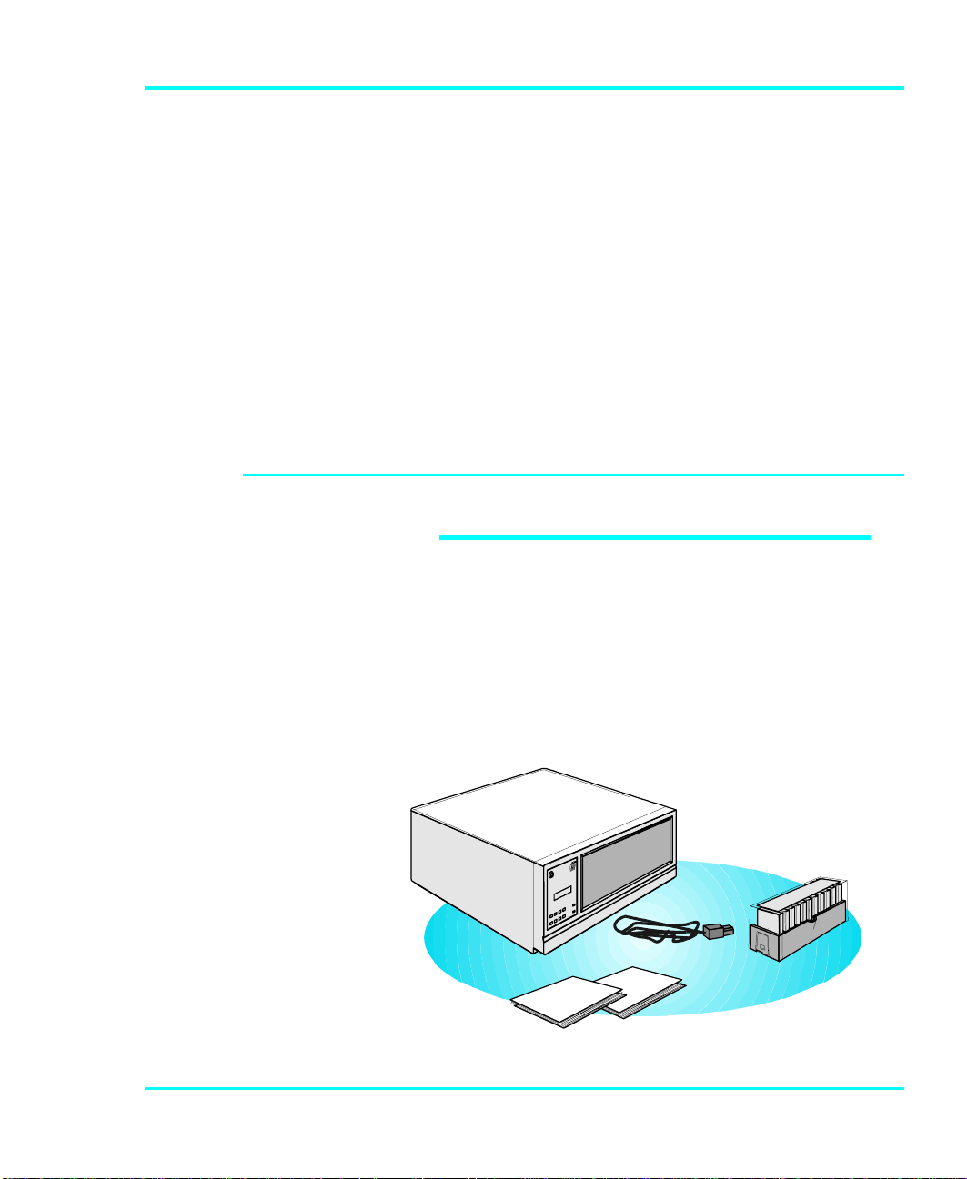
Unpack all items from the carton. Save the packing materials
in case you need to move or ship the system in the future.
a dic
ONLINE R ESET UP DOWN
LOCK
MENU ENTER LEFT RIGHT POWER
Figure 2: VLS Packaging Contents
Getting Started 3
Page 16

You must ship the ADIC VLS in the original or
equivalent packing materials or your warranty may
be invalidated.
Equipment Description
The VLS Unit
The ADIC VLS is a fully automated, high performance, high
capacity, mass storage system designed with a removable
data cartridge magazine. The door can be locked to
deactivate the unit's keypad and to assure only authorized
removal of the magazine and media. In addition, to protect
the unit, data and media, the VLS will not operate unless the
door is closed.
Drives
CAUTION
All drives are available
í
configured for operation
with a single-ended or
differential SCSI bus.
4 Getting Started
The ADIC VLS can be equipped with any of the drives
listed in the following table:
VLS
Model
DLT 400 DLT4000 40GB 180MB/min.
DLT 700 DLT7000 70GB 600MB/min.
Drive
Model
Table 1. Drive Capacity and Transfer Rate
Maximum Capacity
(compressed mode)
Maximum Data
Transfer Rate
(compressed
mode)
Page 17
Magazine
e
Opensideo
f
ADIC strongly
í
recommends that you
use ADIC approved DLT
media only.
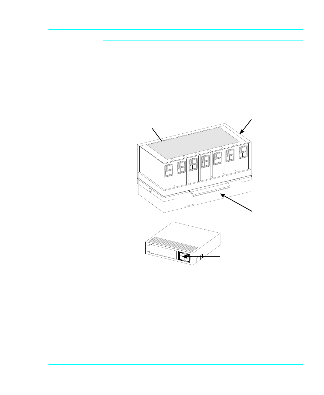
The magazine for the VLS holds seven DLT cartridges. It
includes a clear dust cover to protect the cartridges and for
ease of storage. Figure 3 shows a DLT cartridge and a filled
magazine with the cover in place.
magazine
MagazineCove r
(towards VLS)
Closedside
of magazin
Write-ProtectSwitch
Figure 3. VLS Magazine and DLT Cartridges
Getting Started 5
Page 18
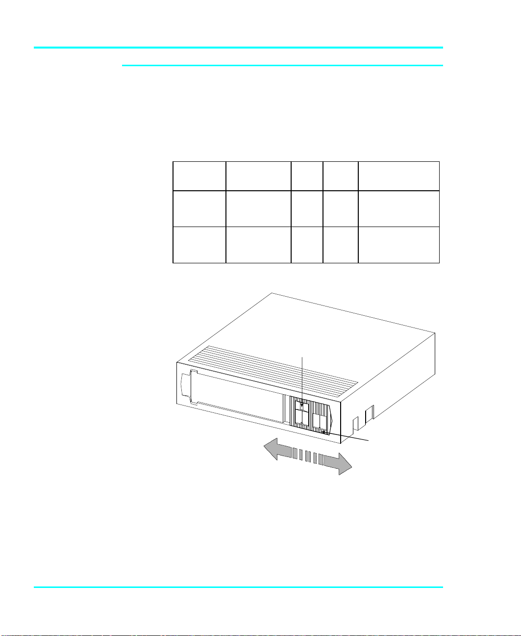
DLT Media
WRITE-PROTECTSWITCH
WRITE-ENABLED
WRITE-PROTECTEDORANGEINDICATO
R
The data cartridges used in the DLT drives are housed in 4inch plastic cases and employ ½-inch metal particle tape.
Table 2 describes and lists the media cartridges that can be
used with the three drive models.
Drive
Model
DLT4000 DLTTape III
DLT7000 DLTTape III
Cartridge
Model
DLTTape IIIXT
DLTTape IV
DLTTape IIIXT
DLTTape IV
Table 2. Media Cartridges
Color Tape
gray
white
black
gray
white
black
Length
1100 '
1800 '
1800 '
1100 '
1800 '
1800 '
Capacity
20 GB (compressed)
30 GB (compressed)
40 GB (compressed)
20 GB (compressed)
30 GB (compressed)
70 GB (compressed)
Figure 4: DLT Data Cartridge
The write-protect switch is used to prevent recording over
existing data. To prevent recording or deleting, place the
write-protect switch to the open position. The drive senses
the position of the switch and will not allow writing in this
6 Getting Started
Page 19

position. When installing cartridges in the library, place the
switch in the closed position (unless you do not wish to
record on a specific cartridge).
If the switch is moved all the way to the left, the cartridge is
write-protected and the drive cannot write to, or erase data
from, the cartridge. The small orange rectangle will be
visible whenever the cartridge is write-protected.
Additionally, an arrow (beneath the orange rectangle and
above the two lines on the switch), lets you know that data
cannot be written to the cartridge. If the switch is moved all
the way to the right, the cartridge is write-enabled and the
drive can write data to, or erase data from, the cartridge. The
orange rectangle will not be visible whenever the cartridge is
write-enabled. On the right side of the write-protect switch
an arrow over one line indicates that if you slide the switch
to the right, data can be written to the cartridge.
Note
• Store data cartridges in a dry, cool environment.
• Never reset or power down your computer or
VLS DLT while a function is in process or a
tape is moving. In addition to getting tape with
missing or corrupted data, you may also get tape
run-on within the drive (a condition that can
produce internal contamination requiring factory
cleaning).
• If a power outage occurs during a back-up
sequence, restart your backup from the
beginning.
Getting Started 7
Page 20
Cleaning Tape
If the cleaning cycle is
í
noticeably shorter and
the Use Cleaning TapeUse Cleaning Tape
LED remains illuminated
after a cleaning
attempt, the cleaning
tape has exhausted all
of its cleaning cycles.
Replace it with the same
type and repeat the
cleaning.
The tape heads should be cleaned when the Use Cleaning
Tape LED on the drive front panel is illuminated. A
cleaning tape is shipped with your ADIC VLS-DLT. Discard
it when there are no cleaning cycles remaining, and replace
it with the same or equivalent type cleaning tape.
Figure 5:. DLT Cleaning Tape
System Software
8 Getting Started
Cleaning the head should always be performed as the first
step if the Use Cleaning Tape LED is illuminated on the
drive front panel.
A variety of backup and data storage software is available
for use with the VLS. Please check with ADIC sales or
Customer Assistance if you have a question on the
compatibility of a particular software package.
Page 21

Preparing the Host Computer System
Power Off the Computer
p Turn off the power switch.
p Unplug the cord from the AC outlet.
Confirm and/or Install the SCSI Host Interface
The host computer
í
system normally is the
server.
The VLS must be connected to either an integrated SCSI
host or a SCSI interface (host adapter card installed in the
computer – either directly to the I/O connector on the card or
as part of an existing SCSI chain. The SCSI interface must
be installed before you connect the VLS. Refer to the
instructions supplied with the card.
Now you are ready to connect the VLS to your host
computer. Follow the instructions provided in the next
chapter.
Getting Started 9
Page 22

Notes
10 Getting Started
Page 23

CHAPTER
CONNECTING THE VLS
This Chapter…
p provides instructions for physically
connecting your VLS to your host system.
2
p steps you through the final phase of the
installation process.
11
Page 24
Connecting the Interface Cables
NOTE: The interface
í
cable must be shielded –
ADIC can supply you with
the correct type.
The bail locks, or jack
í
screws at both ends of
the SCSI cable must be
securely fastened in
order for the VLS to
communicate properly
with the computer.
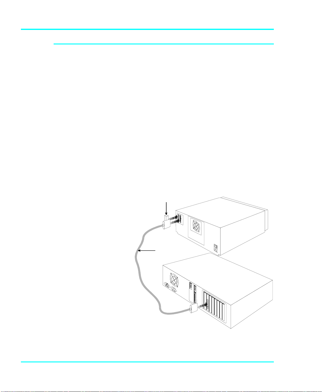
Make sure the SCSI interface cable you are using has the
correct connectors on each end. If it does not, you will need
to obtain a different cable. Consult your dealer or ADIC
Customer Assistance if you need help. Connect the interface
cable as shown in Figure 6 and explained in the following
steps:
p Check that the VLS and host computer power switches
are off.
p Attach one end of the cable to either connector on the
rear of the VLS. Press firmly and secure the bail locks,
or jack screws.
p Plug the other end of the SCSI interface cable into the
external connector on the SCSI port card. Secure firmly.
Terminato r
VLS
SCSI
In terface
Cable
12 Connecting the VLS
Host C omp uter
Figure 6. Connecting the Interface Cable
Page 25
p If this is the only unit you are installing, insert an
2VLSunits
external terminator into the second SCSI connector at
the rear of the VLS. If you plan to connect another unit
on the same SCSI channel, see the next section.
Connecting More than One VLS
When counting SCSI
í
devices, keep in mind
that a VLS can contain
two devices (the drive
and the robotics). Don't
forget to include in your
count other devices on
the SCSI channel, (i.e. a
tape unit, an additional
hard drive, etc.).
* When connecting two
í
or more VLS units to a
single SCSI channel, you
must install a ferrite
bead on the cable. Refer
to Appendix A for
details.
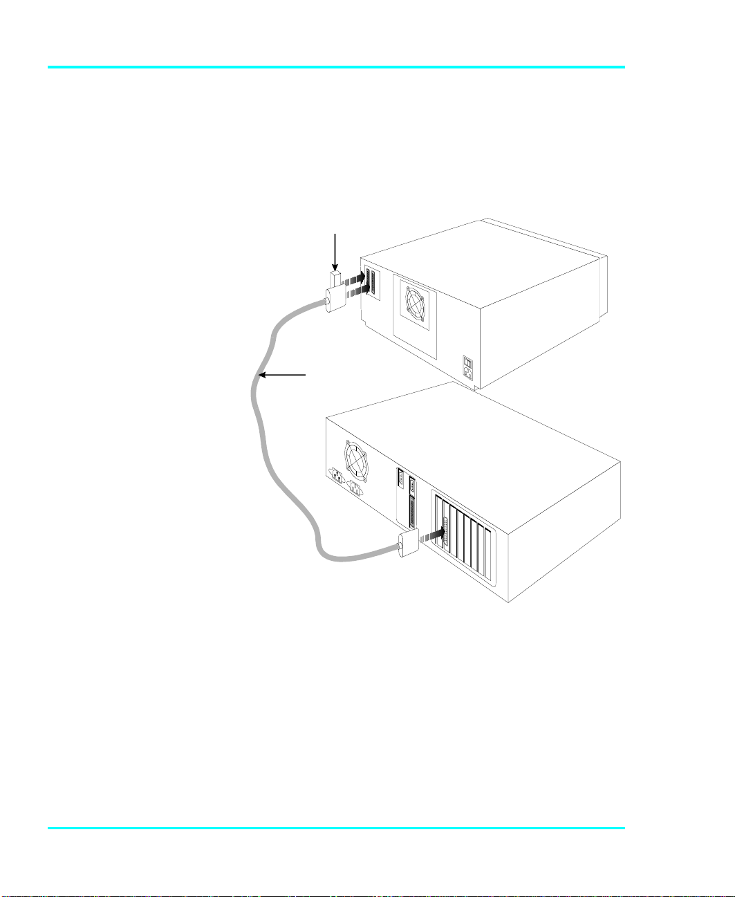
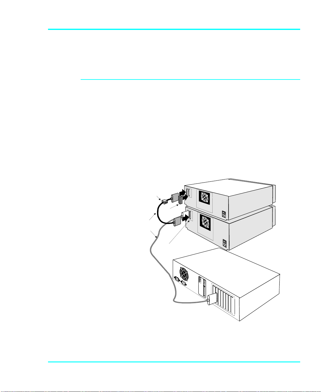
If you are connecting additional VLS units on the same
SCSI channel, simply attach each subsequent unit to the
previous unit with an interface cable. Make sure all cables
are properly secured. It makes no difference which
connector you use for each connecting cable (see Figure 7).
You can attach up to seven devices on each SCSI channel
(8-bit), or up to fifteen devices on each wide SCSI channel,
but each VLS may represent more than one SCSI device.
*Fe rrite
Be ad
SC S I
Interfac e
C able
Term inator
I/O
C onn ectors
Host
Com p uter
(O n sa me
SC S I
Ch a n n e l)
Figure 7. Cable Diagram for two VLS Units
Each VLS unit contains more than one SCSI device and may
require more than one SCSI address (depending on the mode
Connecting the VLS 13
Page 26
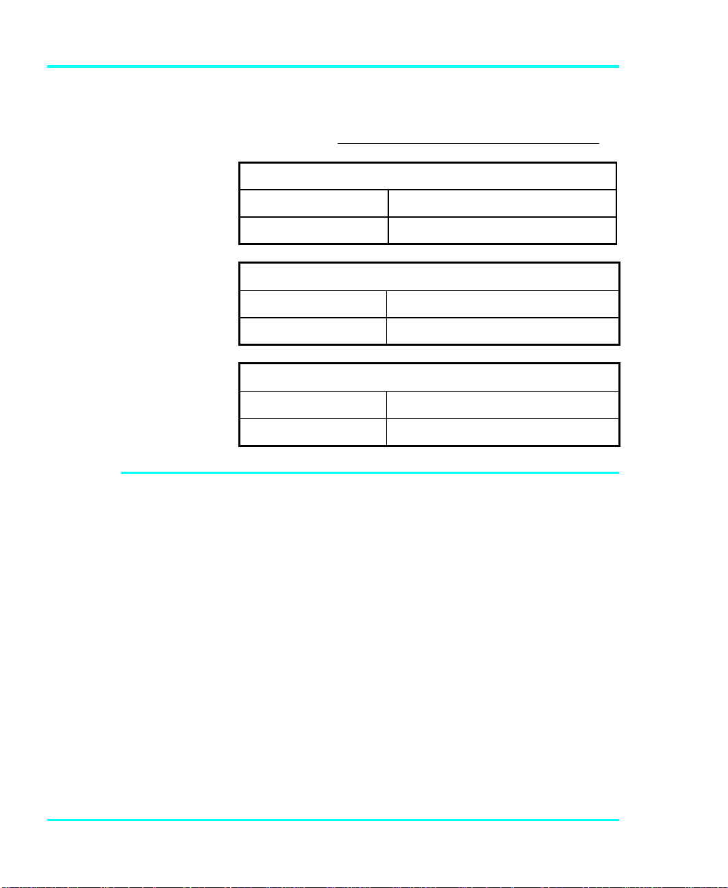
of operation). The following chart shows the number of
SCSI addresses required in each operating mode. The second
chart illustrates how many VLS units you can attach to one
SCSI channel (if there are no other devices on the channel).
Number of SCSI Addresses Required
Sequential Mode
1 2
Maximum VLS units on one SCSI Channel (8-bit)
Sequential Mode Random Mode
7 3
Maximum VLS units on one wide SCSI Channel
Sequential Mode Random Mode
15 5
Powering on the System
p Plug the power cord into the back of the VLS.
p Plug the power cord from the VLS into a grounded
electrical outlet.
Random Mode
p Plug the power cord from your host computer into a
p Turn on the VLS power. Turn on the host computer
14 Connecting the VLS
grounded electrical outlet.
power.
Page 27

A display similar to the following will appear:
You are now ready to install the backup software – if it has
not already been installed.
Installing the Backup Software
This is the software
í
that runs the VLS, not
the data being
transferred to the VLS
cartridges. Two
examples of backup
software are Cheyenne's
ARCserve and Legato's
NetWorker.
At this point you need to refer to your software installation
guide for instructions on installing the backup/controlling
software for the VLS onto the host computer.
After you have completed installation of the VLS unit and of the
software, to make sure your unit is operating correctly, you
should run any diagnostic test(s) supplied with the backup
software.
Connecting the VLS 15
Page 28

Notes
16 Connecting the VLS
Page 29

CHAPTER
EQUIPMENT DESCRIPTION
This Chapter …
p describes the switches, indicators and
connectors on the front and rear of the VLS.
p describes the various functions available via
the front panel buttons.
3
p describes the power-up procedure and
messages on the front panel LCD display.
17
Page 30
Note: The pick arm must
í
be in its out position.
You can move it
manually when power is
off (or with [ALT] and
[UNLOAD] when power is
on).
Front Panel Switches and Indicators
For the most part, once your Virtual Library System has
been connected to your host computer system and the
software has been installed, the VLS is ready for use. Just
turn on the power switch, place a magazine on the carriage
and press ALT and then LOAD.
If you need to change certain functions, you can use the
front panel keys (as described in the next section).
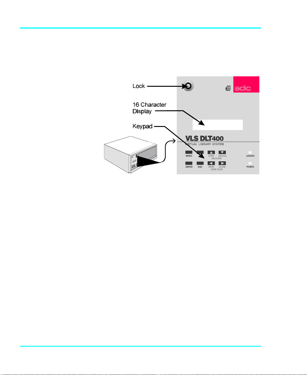
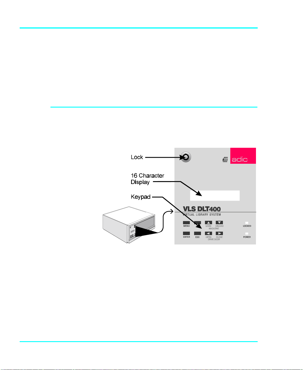
Switches and indicators on the front of the VLS are shown
in Figure 8 and described in Tables 2 and 3.
18 Equipment Description
Figure 8. Front Panel Display and Keypad
Page 31

INDICATOR Description
Display The two-line 16-character LCD shows current drive
status of the VLS, allows access to change features or
displays error messages.
The VLS uses the LOAD
í
function to detect
cartridges (or the
absence of a cartridge).
Never attempt to
í
remove a magazine
unless it is in the unload
position – you may
damage the pick arm.
Power LED
(green)
Locked LED
(green)
Lights up when the power is on.
Lights up when door is locked. No one can access the
magazine, drive or keypad when the Locked LED is
on.
Table 2. Front Panel Indicators
KEY Description
MENU Press this button to enter or exit Off-Line Mode menus
and mode
ALT Selects alternate function for another button. For
example, press the ALT button and the UP button
to activate the load function.
Selects previous item or value in the menu.
LOAD
MAGAZINE
UNLOAD
MAGAZINE
Press the ALT button and then this button to initiate a
"load magazine" – the VLS will check all cartridges in
the magazine (making note of empty spaces) and that
all cartridges can be inserted in the drive.
Selects next item or value in the menu.
Press the ALT button and then this button to initiate
the unload program – the VLS will return the
magazine to the unload position.
This function is available for
í
all VLS models with firmware
version 2.32 or later.
This function is available for
í
all VLS models with firmware
version 2.32 or later.
ENTER Selects currently displayed item.
ESC Exits current menu and returns to previous menu.
Scrolls message display left or selects previous field.
Open Door
Close Door
Press the ALT button and then this button to open the
drive door.
Scrolls message display right or selects next field.
Press the ALT button and then this button to close the
drive door.
Table 3. Front Panel Keypad
Equipment Description 19
Page 32

Rear Panel Switches and Connectors
SCS
I
Panel
d
PowerSwitch
Switches and connectors on the rear of the VLS are shown
in Figure 9 and described in Table 4.
Connectors
F an
F ilter
Rear
Access
Power
Switch
AC Power
Connector
SCSI I/O
Connectors
Table 4. Rear Panel Switches and Connectors
AC Power
Connector an
Figure 9. VLS Rear Panel
Turns on the AC power to the VLS.
Plug the VLS AC power cord into this
connector.
For the interface cable that connects the
VLS to the computer, to other VLS units
and/or to other devices on the SCSI
channel.
20 Equipment Description
Page 33

Menu Items
Use the following diagram as a quick reference once you
have become familiar with the LCD menus described on the
next few pages. The names at the top of the diagram are
selections available from the Main Menu. When you choose
one of the Main Menu items, a set of options appears; these
options are listed below the Main Menu selections. If an
option has sub-options, these sub-options are listed to the
right of the option.
Equipment Description 21
Page 34

Configuration Menu Diagnostics Menu Write EEPROM Mode
Buzzer Configuration Error Counters
ErrAlarm Yes/No Event Counters
Kybd Yes/No Operation Log
SCSI ID Config Firmware Revision
Drive (0-7) Serial Number
Changer (0-7) Position Magazine
SCSI Parity Opn/Cls Drv Dr
Parity Check Yes/No Load Medium
Off-line Time Unload Medium
Max time 1-99 min
On-line Mode Random/Sequential
Sequential Mode Cfg
First (0-11)
Last (0-11)
Loopback Yes/No
Prod. Sign-On
VLS 8mm Yes/No
Unload Drives
22 Equipment Description
Page 35

To access the Off-Line Menu, press the MENU key. The
display will read as follows:
Use the or buttons to scroll through the menu. Press
ENTER to select a displayed item. Use the or buttons
to scroll through fields on the same line.
To exit the Off-Line Menu press the MENU button.
Configuration Menu
The Configuration Menu allows you to select the following
items:
• Buzzer Config • SCSI ID Config
• SCSI Parity • Off-Line Time
• On-Line Mode • Seq Mode Config
• Prod. Sign-On
Buzzer Configuration
Enables/disables alarm when there is an error message.
Enables/disables keyboard beep sound when you press a
button.
To enable the alarm mode use the button to select the
ErrAlarm field. Use or to select "Y" to enable or "N" to
disable alarm. When ErrAlarm is enabled, a continuous
alarm will sound in the event of an error message. The alarm
will sound until the condition that caused the error has been
Equipment Description 23
Page 36

removed or any key is pressed. (To clear an error message,
press ALT and ENTER.)
To disable the keyboard beep, use the button to select the
Kybd field. Use to select "N" to disable the beep.
Buzzer Configuration
í
default: ErrAlarm:N,
Kybd:Y
SCSI ID Configuration
í
default: Drive :1
Changer:3
Press ENTER to make the changes effective or press ESC
to return to previous menu item.
SCSI ID Config
Lets you select the SCSI ID for the drive and the robotics on
the VLS.
Use or to select the desired field. Drv is the drive, and
Changer is the robotics unit on the VLS. Use and to
scroll to the desired ID for that particular element. Press
ENTER.
Note
SCSI ID changes entered do not take effect until you
cycle power on the VLS unit.
See the section titled Connecting More than One VLS in
Chapter 2: Connecting the VLS noting the number of SCSI
IDs required.
24 Equipment Description
Page 37

SCSI Parity default:
í
Parity Check:N
SCSI Parity
Enables or disables the reporting of SCSI parity check.
Use or to select "Y" to enable, or "N" to disable the
reporting of parity check. Press ENTER to activate the
change.
Off-Line Time
Lets you set the number of minutes the VLS will remain in
the Off-Line mode. If someone leaves the VLS in the OffLine Mode, after the pre-set number of minutes the VLS will
automatically return On-Line. This assures that your
automatic backup will be done even if the VLS has
accidentally been left Off-Line.
Off-line time default
í
setting is "5" minutes.
The software you use
í
with the VLS determines
whether you can operate
the VLS in sequential
and/or random mode.
Use or to select the number of minutes you wish the
VLS to remain Off-Line. Press ENTER to execute the
change.
On-line Mode
Lets you select random or sequential operating mode.
When in random-access mode, the VLS allows software
selection of any cartridge in the magazine in any order. You
can logically divide cartridge usage to satisfy particular data
storage needs. For example, you can assign one or more
cartridges to specific data functions (such as certain
directories or network servers), or you can assign specific
cartridges to individual users.
Equipment Description 25
Page 38

Operating Mode default
í
setting is "Random".
ADIC's VLS can also be used as a stacker in sequential
mode if your software does not support the random mode
function.
A display similar to the following will appear:
Use or to select "random" or "sequential."
Sequential Mode Configuration
If you are using Sequential Mode, this option lets you select
which cartridges the drive will write to, and whether or not
you wish the drive to start again at the beginning after the
last cartridge has been written to.
Use or to select the item you wish to change. "F" is the
number of the First cartridge you wish the VLS to insert into
the drive. "L" is the number of the Last cartridge you wish
the VLS to insert into the drive.
Default setting is
í
F: 01 L: 11 Lpbk: Y
The Loopback (LPBK) mode determines what happens
when the last cartridge has been filled. If you select "Y" for
"Lpbk" the designated first cartridge will be loaded into the
tape drive after the last cartridge has been filled and ejected.
If you select "N" an error message will be issued and the
backup will stop.
Product Sign-On
Normally, the VLS DLT will sign-on as a VLS DLT product
and most application software will support it.. However,
some older software will not recognize it as a VLS DLT. If
26 Equipment Description
Page 39

Product Sign-On default
í
is "VLS 8mm : N".
your software does not recognize it, change the Product
Sign-On to Use “VLS 8mm”: Y.
Use or to select "Y" for VLS 8mm, or "N" to select
VLS DLT.
Note
Product Sign-On changes entered do not take effect
until you cycle power on the VLS unit.
Diagnostics Menu
The following items are available under the Diagnostics
Menu:
• Error Counters • Event Counters
• Operation Log • Serial Number
• F/W Revision • Position Magazine
• Opn/Cls Drv Dr • Load Medium
• Unload Medium • Unload Drive
For information on these options, refer to Appendix C later
in this manual.
Equipment Description 27
Page 40

Write EEPROM Mode
The Write EEPROM Mode is used whenever you upgrade
the VLS firmware. When ADIC releases new firmware for
the VLS, complete instructions on using Write EEPROM
Mode and performing the upgrade will be included with the
new firmware.
28 Equipment Description
Page 41

OPERATION AND
MAINTENANCE
CHAPTER
4
This Chapter …
p describes normal operation features of the
VLS
p provides details on the media and magazine
p explains normal maintenance procedures
29
Page 42

Since the drive status
e
Opensideo
f
í
LEDs are located on the
top front of the drive, to
see them you must be
eye-level with the gripper
arm of the VLS. Look
beyond the arm to the
drive.
Inserting the Data Cartridges into the Magazine
The VLS DLT is a highly sophisticated unit composed of
one DLT drive along with the robotics that control the drive,
magazine and media. No modifications have been made to
the drive. The built-in drive status LEDs function as the
manufacturer has specified.
Very little routine maintenance is required – apart from
cleaning the head whenever the Use Cleaning Tape LED
is illuminated on the drive front panel (see Cleaning the
Drive Head later in this chapter).
ADIC strongly
í
recommends that you
use ADIC-approved
media only.
The magazine for the VLS DLT holds seven DLT cartridges.
It includes a clear dust cover to protect the cartridges and for
easy storage. See Figure 10. Insert each cartridge into a slot
of the magazine making sure that the write-protect switch is
toward the top, facing the closed side of the magazine (as
illustrated).
magazine
MagazineCover
(towardsVLS)
Closedside
of magazin
Write-ProtectSwitch
30 Operation and Maintenance
Figure 10. Magazine for VLS
Page 43

Be very careful when
í
handling the magazine.
The cartridges can fall
out once the cover has
been removed.
The open side of the magazine faces the VLS. Make sure
each cartridge touches the bottom floor of the magazine.
Do not use wrap-around labels on the individual cartridges.
Most labels use a removable adhesive and have a tendency
to curl or tear after multiple uses. This can jam the
movement of the VLS. Place labels only in the space
provided on the cartridge.
Note the following:
p Store magazines (and data cartridges) in a dry, cool
environment. Keep the dust cover on each magazine.
p Never reset or power down your computer or VLS
unit while a function is in process or a tape is
moving. In addition to a tape with missing or
corrupted data, you may also get tape run-on within
the drive (a condition that can produce internal
contamination requiring extra cleaning).
p If a power outage occurs during a back-up sequence,
restart your backup from the beginning.
Inserting the Magazine into the VLS
Warning
Due to static the label or other items included in this
package will occasionally cling to the DLT
cartridge.
Before loading into a drive, ensure that all other items from
this package are separated from the cartridge.
Operation and Maintenance 31
Page 44

Do not attempt to place
í
a covered magazine onto
the VLS carriage.
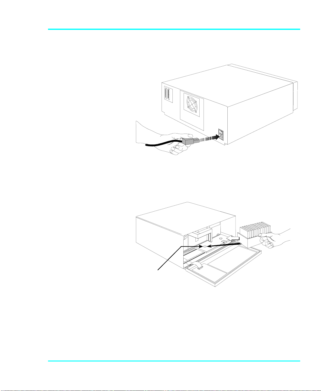
p Remove the magazine dust cover. You can remove the
cover by pressing the middle of both ends (where it is
labeled PUSH) and lifting up (see Figure 9).
p Open the VLS door. (The pick arm must be in the "out"
position before you try inserting a magazine.)
p Holding the magazine by the handle, and at a 45º angle
to the carriage, slip the magazine onto the left side of the
carriage, over the left magazine position pin (see Figure
11).
Left Magazine
Positi on Pin
Push the right side of the magazine over the right magazine
position pin until you hear a click. See Figure 12.
32 Operation and Maintenance
Figure 11. Placing the Magazine onto the VLS
Page 45

You may need to apply
í
downward pressure as
you slip the magazine
over the right magazine
pin and then press the
magazine into place with
your index finger.
Loading the Magazine
Figure 12. Pushing the Magazine in Place
The magazine will snap into place. If you don't hear a click,
make sure that the slot on the right side of the magazine has
slipped around the right magazine position pin and is not
just sitting on top of it (the magazine will not load correctly
in this position).
Once you have placed the magazine on the carriage, the VLS
must initiate a loading process. During this procedure the
VLS checks and maps the position of each cartridge and
makes sure that all cartridges are inserted into the magazine
correctly. If you are using the sequential mode the VLS
inserts the first cartridge into the drive.
The door must be closed
í
before the LOAD or
UNLOAD functions will
activate.
p
Make sure the magazine is placed correctly on the carriage.
p Close the door and press ALT and then LOAD. The VLS
will initiate the load magazine procedure.
Note
In the sequential mode, if you press UNLOAD
before the VLS has finished loading the magazine,
the robotics will finish mapping and checking the
cartridges and then move the magazine to the unload
position (the far right) without inserting a cartridge
into the drive.
Operation and Maintenance 33
Page 46

In random mode, if the VLS has not finished loading
the magazine, pressing UNLOAD will have no
effect.
Attempting to Load the Magazine with a
Cartridge Already in Drive
If your VLS is equipped with firmware version 2.31 or
earlier, refer to Appendix C.
Random Mode: If the cartridge was loaded manually, it
must be unloaded manually – before you attempt to have the
VLS load the magazine. Refer to the next section for manual
removal of a cartridge. If the VLS robotics was used to load
the cartridge via applications software, attempting to "load
magazine" from the keyboard will fail – the unit will remain
On-Line.
Sequential Mode: If the cartridge was loaded manually, it
must be unloaded manually – before you attempt to have the
VLS load the magazine. Refer to the next section for manual
removal of a cartridge. If the VLS robotics was used to load
the cartridge, the VLS will remember and not allow a "load
magazine" from the keyboard. Press ALT and then ENTER
to bring the VLS back On-Line.
Manually Removing a Cartridge Loaded in the
Drive
Follow this procedure to remove the cartridge from the drive
if it was loaded manually, not by the application software or
by using the Diagnostics Menu.
p Press ALT and then UNLOAD. This will place the
magazine in the unload position.
34 Operation and Maintenance
Page 47

p Open the VLS door and remove the magazine by
pressing the Magazine Release.
p Press the UNLOAD button on the drive front panel (see
figure 13 for location).
p Close the VLS door.
p On the VLS front panel, first press ALT, then the OPEN
DOOR keys.
p Open the VLS door and remove the ejected cartridge
from the drive.
p If the cartridge was loaded into drive from the magazine
place it back in the correct slot.
p Replace the magazine onto the carriage.
p Close the door. You can now initiate the load procedure.
Removing a Cartridge Loaded in the Drive Using
the Diagnostics Menu
Use this procedure to load the magazine if there is a
cartridge in the drive, and the cartridge was loaded by either
the application software or by using the Diagnostics Menu.
p Open the VLS door.
p Press the UNLOAD button on the drive front panel (see
figure 13 for location). The drive will prepare the
cartridge for ejection.
p Close the VLS door.
p To access the Diagnostics Menu, press the MENU
button. The display will read as follows:
Operation and Maintenance 35
Page 48

p Press to access the Diagnostics Menu. A display
similar to the following will appear:
p Press ENTER to select the Diagnostics Menu.
p Press to move to the Opn/Cls Drv Dr option. A
display similar to the following will appear:
p Press ENTER to select the Opn/Cls Drv Dr option. The
drive will eject the cartridge and the pick arm will place
it back in the magazine.
p You can now initiate the load procedure.
Removing the Magazine from the VLS
If your VLS is equipped with firmware version 2.31 or
earlier, refer to Appendix C.
36 Operation and Maintenance
Page 49

You cannot initiate an
and (UNLOAD) buttons.
í
(UNLOAD), or remove
the magazine, if the door
is locked. When the
locked LED is on, the
VLS ignores the (LOAD)
Before physically removing the magazine from the carriage,
you must first initiate the UNLOAD procedure.
p Make sure there is no cartridge in the drive. If there is,
go to the next procedure, Removing the Magazine with a
Cartridge in Drive.
p Press ALT and then UNLOAD and wait until the unload
procedure is finished. (If the carriage is not in the unload
position, it will move to the right. In addition, the
grippers on the pick arm will close.)
p Press the Magazine Release on the carriage. The
magazine will release from the holding pins.
M a g az in e
R e le a se
í
Make sure you have
labeled each cartridge
as to magazine and slot
number. The magazine
slots do not restrain
the cartridges, and if
you tip or drop the
magazine, the
cartridges will fall out.
Figure 14. The Magazine Release
p Grab the thumb handle on the magazine and pull the
right side of the magazine toward you. The magazine
will come out at a 30º- 40º angle.
p Place the transparent cover over the magazine and store
the unit in a cool, dry place.
Operation and Maintenance 37
Page 50

Removing the Magazine while a Cartridge is in
the Drive
If you wish to remove the magazine but there is a cartridge
in the drive, do the following:
p Open the VLS door.
p Press the UNLOAD button on the drive front panel (see
figure 13).
p Close the door of the VLS.
p Press ALT and then UNLOAD. The arm will return the
cartridge to the magazine slot and the VLS will move
the magazine to the unload position.
p Remove the magazine as noted earlier.
Loading an Individual Cartridge
If your VLS is equipped with firmware version 2.31 or
earlier, refer to Appendix C.
If for some reason you need to use a single cartridge, you
can load it manually or semi-automatically, using the VLS
robotics controlled by the Diagnostics Menu.
Manually Loading a Cartridge
p Unload the magazine by pressing ALT and then
UNLOAD. The magazine will move completely to the
right.
p Open the door and remove the magazine from the
carriage. (See instructions in previous section Removing
the Magazine from the VLS).
38 Operation and Maintenance
Page 51

p Close the VLS door.
p On the VLS front panel, first press ALT, then the OPEN
DOOR keys.
p Open the VLS door.
p Insert the cartridge into the drive opening with the label
facing you and the write-protect switch up.
p Close the VLS door.
p On the VLS front panel, first press ALT, then the
CLOSE DOOR keys.
p If the drive does not eject the cartridge when the
program is finished, follow the procedure described in
Manually Unloading a Cartridge Loaded in the Drive
earlier in this chapter.
Semi-automatically Loading a Cartridge
p Take the VLS-DLT to the Off-Line Mode by pressing
the MENU key on the Operator Panel.
p Unload the magazine by pressing ALT and then
UNLOAD. The magazine will move completely to the
right.
p Open the door and remove the magazine from the
carriage. (See instructions in previous section Removing
the Magazine from the VLS).
p Place the cartridge that you want to use into an empty
slot of the magazine.
p Replace the magazine onto the carriage.
p Close the VLS door.
Operation and Maintenance 39
Page 52

p Load the magazine by pressing ALT and then LOAD.
The VLS will map the magazine.
p Use the key to scroll the display to the
Diagnostic Menu option.
The display will now show:
p Press the ENTER key to select the Diagnostic Menu.
Use the key to scroll the display to the LOAD MEDIUM
option.
The display will now show:
Use the key to move to the Slot field. Use the or
keys to select the slot you want to load from. Press
ENTER. The VLS will load the cartridge into the drive.
If the drive does not automatically eject the cartridge when
the program is finished, follow the procedure described in
Manually Removing a Cartridge Loaded in the Drive earlier
in this chapter.
p Return the VLS DLT to On-Line Mode by pressing
MENU.
Your VLS DLT library is once again ready for use.
40 Operation and Maintenance
Page 53

Unloading an Individual Cartridge
Semi-automatically Unloading a Cartridge
If you have used the VLS robotics and the Diagnostics Menu
to load a single cartridge, you should unload it the same
way.
Note
Observe the drive status on the display. The VLS
should be displaying the slot number of the
magazine that you previously loaded the cartridge
from. If it is not, you should not use this procedure
to unload the cartridge. Instead, follow the
instructions in Manually Removing a Cartridge
Loaded in the Drive earlier in this chapter.
p Take the VLS-DLT to the Off-Line Mode by pressing
the MENU key on the Operator Panel.
p Use the key to scroll the display to the
Diagnostic Menu option.
The display will now show:
p Press the ENTER key to select the Diagnostic Menu.
Note
The VLS knows which slot to return the cartridge to,
it is not necessary to position the magazine, the VLS
will do this automatically.
Operation and Maintenance 41
Page 54

p Open the VLS door.
p Press the UNLOAD button on the drive front panel (see
figure 13).
p Close the VLS door.
Use the key to scroll the display to the UNLOAD
MEDIUM option.
The display will now show:
Press ENTER. The VLS will unload the cartridge and
return it to the magazine.
p Return the VLS DLT to the On-Line Mode by pressing
MENU.
Your VLS DLT library is once again ready for use.
Removing a Cartridge from the Magazine
The data cartridges easily slip into and out of the slots of the
magazine. To remove a cartridge, simply grasp it with two
fingers and pull up. Make sure each cartridge is labeled so
you know the contents (and where it belongs in the magazine
sequence).
Remember – Do not use wrap-around labels on the
individual cartridges. Most labels use a removable adhesive
and have a tendency to curl or tear after multiple uses. This
can jam the movement of the VLS. Place labels only in the
space provided on the cartridge.
Storing the Magazine
42 Operation and Maintenance
Page 55

Store magazines in a dry, cool environment. Always keep
the dust cover on the magazine.
The removable magazine allows for long-term archiving or
off-site safety storage of groups of cartridges.
You can duplex multiple VLS units so your system can
mirror data backups on each separate unit. With duplexing
you have real time data assurance and the ability to remove
one magazine for off-site storage while the other remains for
on-line data access.
Cleaning the Drive Head
If your VLS is equipped with firmware version 2.31 or
earlier, refer to Appendix C.
Cleaning Tape
The tape heads should be cleaned when the Use Cleaning
Tape LED is illuminated on the drive front panel.
Figure 15. DLT Cleaning Tape
Cleaning the head should always be performed as the first
step if the Use Cleaning Tape LED is illuminated.
The following table tells you when to use the cleaning tape:
If . . . It means . . . You should . . .
Operation and Maintenance 43
Page 56

1. The Use Cleaning Tape
LED is illuminated on the
Operator Panel
The drive head needs cleaning
or the tape is bad
Use the cleaning tape. Load the
cleaning tape using the
procedure in section Cleaning
Head Procedure
When cleaning is complete, the
beeper will sound alerting you
to remove the cleaning tape. Use
the procedure in subsection
Unloading a Cartridge from
Drive to remove the cleaning
tape from the drive.
2. A data cartridge causes the
Use Cleaning Tape LED
to be illuminated on the
Operator Panel
3. The Use Cleaning Tape
LED remains illuminated
on the Operator Panel after
you clean the drive head.
4. The Use Cleaning Tape
LED re-illuminates on the
Operator Panel after you
load the cleaning tape
The data cartridge may be
damaged
Your data cartridge may be
causing the problem
Cleaning has not been
accomplished and the cleaning
tape has no remaining cycles
available.
Back up the data from this
cartridge onto another cartridge,
it may be damaged. A damaged
cartridge may cause unnecessary
use of the cleaning cartridge.
Try another data cartridge.
Replace the cleaning tape.
Caution
Using cloth swabs, cotton swabs, cleaning agents, or
unapproved cleaning tapes will void your warranty.
Use only an ADIC-approved cleaning tape.
Head Cleaning Procedure
Clean the drive head and tape path whenever the Use
Cleaning Tape LED is illuminated. The cleaning
frequency does not depend on the format in which you write
and read data.
44 Operation and Maintenance
Page 57

If your application software cannot, or is not configured to
automate the cleaning cycle, follow these cleaning directions
carefully to assure that no damage will occur to your VLSDLT, a tape drive, or media.
Some application
í
packages may allow a
magazine slot to be
used for a cleaning
cartridge and automate
its use. Refer to your
application software
manual.
Please follow these cleaning directions carefully to assure
that no damage will occur to the drive, VLS or media.
p Unload the magazine by pressing ALT and then
UNLOAD. The magazine will move completely to the
right.
Loading from Dedicated Magazine Slot
If your cleaning tape is inserted in a dedicated magazine slot
perform the following steps:
p Take the VLS-DLT to the Off-Line Mode by pressing
the MENU key on the Operator Panel.
p Use the key to scroll the display to the
DIAGNOSTIC MENU option.
The display will now show:
p Press the ENTER key to select the Diagnostic Menu.
Use the key to scroll the display to the LOAD MEDIUM
option.
The display will now show:
Use the key to move to the Slot field. Use the or
keys to select the slot you want to load the cleaning tape
Operation and Maintenance 45
Page 58

from. Press ENTER. The VLS will load the tape and the
cleaning cycle will begin.
p To confirm that a cleaning was done, check the Use
Cleaning Tape LED on the drive front panel. If the
cleaning cycle was successful, the LED will no longer
be illuminated. If the cleaning cycle was not performed,
the Use Cleaning Tape LED will still be illuminated.
Returning the Cleaning Tape to the Magazine
p Open the VLS door.
p Press the UNLOAD button on the drive front panel (see
figure 13).
p Close the VLS door.
Note
The VLS knows which slot to return the cleaning
tape to, it is not necessary to position the magazine,
the VLS will do this automatically.
Use the key to scroll the display to the UNLOAD
MEDIUM option.
The display will now show:
p Press ENTER. The VLS will unload the cartridge and
return it to the magazine.
p Return the VLS DLT to the On-Line Mode by pressing
MENU.
Your VLS DLT library is once again ready for use.
46 Operation and Maintenance
Page 59

Caution
Cleaning cartridges are considerably more abrasive
to the drive's recording head than standard data
cartridges. Usage should be kept within the
recommended limits, or the warranty may not be
applicable to the affected equipment.
Manually Loading a Cleaning Tape
To load a cleaning tape manually follow these instructions:
p Unload the magazine by pressing ALT and then
UNLOAD. The magazine will move completely to the
right.
p Open the door and remove the magazine from the
carriage. (See instructions in earlier section Removing
the Magazine from the VLS).
p Close the door and press ALT, then press the Open
Door key.
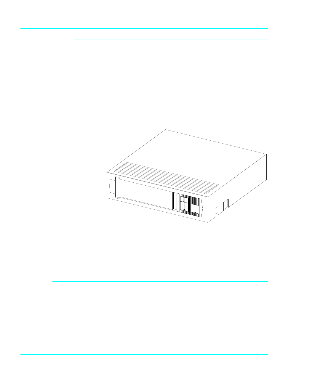
p Open the door and insert the cleaning tape into the drive
opening with the label facing you (see Figure 16).
p Close the door and press ALT, then press the Close
Door key.
Operation and Maintenance 47
Page 60

Figure 16. Inserting the Cleaning Tape
The cleaning cycle will run automatically.
p To confirm that a cleaning was done, check the Use
Cleaning Tape LED on the drive front panel. If the
cleaning cycle was successful, the LED will no longer
be illuminated. If the cleaning cycle was not performed,
the Use Cleaning Tape LED will still be illuminated.
Removing the Cleaning Tape from the Drive
p Press the UNLOAD button on the drive front panel.
p Close the door and press ALT, then press the Open
Door key.
p Open the VLS door, remove the cleaning tape and set it
aside.
p Place the magazine onto the carriage. Close the VLS
door. Press ALT and then LOAD to initiate the load
procedure.
Your VLS DLT library is once again ready for use.
48 Operation and Maintenance
Page 61

Cleaning the Enclosure
The outside of the enclosure can be cleaned with a damp
towel. If you use a liquid all-purpose cleaner, apply it to the
towel. Do not directly spray the enclosure.
Operation and Maintenance 49
Page 62

Blank Page
50 Operation and Maintenance
Page 63

CHAPTER
TROUBLESHOOTING AND
DIAGNOSTICS
This Chapter …
p contains some general suggestions to aid
you in solving problems – should you ever
run into them.
5
p includes information on error codes and the
built-in diagnostics.
51
Page 64

Installation Problems
Usually, problems encountered during the installation of
your library are caused by improper SCSI bus configuration,
application software configuration errors or by an OS that
has not been correctly configured. If the application software
that you are attempting to use is not communicating with
your VLS DLT after installation, check the following:
4 SCSI IDs
Make sure that the IDs you selected for the robotics
and tape drive are not the same as the ID used by
any other SCSI device on that bus, including the
host SCSI adapter card.
The length of the VLS
í
DLT internal SCSI cables
is 3 feet. This length
must be included in any
calculations of cable
length.
For a list of compatible
í
SCSI adapters and
application software,
call ADIC’s Customer
Assistance Center at
(206) 883-HELP.
4 SCSI Cabling
Verify that all SCSI cables are securely connected at
both ends and that the bail locks are secured. Also,
check the length and integrity of your SCSI cabling.
The total length of all SCSI cables must not exceed
19.7 feet (6.0 meters) for single-ended
configurations and 82 feet (25 meters) for
differential configurations. Try replacing suspected
cables with known good cables.
4 Termination
Check that all SCSI buses are properly terminated.
4 Compatibility
Ensure sure that your library and its tape drives are
compatible with the SCSI adapter card and
application software you plan to use.
4 SCSI Adapter Card Installation
Verify that you have installed your SCSI adapter
card correctly. Refer to the documentation that came
with your card for installation and troubleshooting
instructions. Pay particular attention to any steps
describing the settings of various jumpers and/or
52 Troubleshooting and Diagnostics
Page 65

switches on the card. Check that the card is seated
fully in your computers I/O connector.
4 Application Software Installation
Refer to the documentation included with your
software for instructions on how to verify
installation.
Library and Drive Operational Problems
Most problems with the operation of your VLS and/or DLT
drive happen when the drive is not cleaned regularly or
when you use incorrect data cartridges. If you have been
successfully operating the application software and library in
the past, but are now experiencing problems reading and
writing data, check the following:
4 If you are writing data, make sure that the cartridge
is write enabled (move the write-protect switch to
the enabled position).
4 Check the data cartridge you are using. The
DLT4000 and DLT7000 drives can use DLTTape
III, DLTTape IIIXT, and DLTTape IV cartridges.
4 If the cartridge has been in use for a long time or if it
has been used frequently, try using a new cartridge.
4 Clean the drive head.
Troubleshooting and Diagnostics 53
Page 66

Library Error Messages
If any component of the VLS is not communicating
correctly, a warning message will appear on the front
display.
In all cases, after removing the cause of the problem (or if
you can't find a cause) push MENU to return the VLS DLT
to the On-Line Mode.
Most error messages are self-explanatory and give a good
indication of the problem. If the error message does not
clearly indicate what the problem may be, try to return to
the On-Line Mode by pressing ALT and/or ENTER. If that
does not work, or if the error message reappears, call the
ADIC Customer Assistance and be prepared to tell them
what the error message is – and what the conditions are (see
When You Call ADIC Customer Assistance later in this
chapter).
.
54 Troubleshooting and Diagnostics
Page 67

Drive Status and Warning Signals
Normally, the Operator Panel will display error messages
that describe a problem with a drive. The following table of
drive LED messages is provided as additional information.
Label Color State Operating Condition
LED
(Right Indicator Panel)
Write Protected
Tape in Use
Use Cleaning Tape
Operate Handle
Orange ON
OFF
Yellow Blinking
ON
Yellow ON
Remains on after
unloading cleaning
tape
After cleaning,
turns on again
when reloading
data cartridge
Green ON
OFF
Tape is write-protected.
Tape is write-enabled.
Tape is moving.
Tape is loaded; ready for use.
Drive head needs cleaning, or the tape
is bad.
Cleaning attempted, but tape expired,
so cleaning not performed.
Problem data cartridge. Try another
cartridge.
OK to operate the Cartridge
Insert/Release Handle.
Do not operate the Cartridge
Insert/Release Handle.
All Right Indicator
Panel LEDs or,
All Left Indicator Panel
LEDs
ON
Blinking
POST is starting.
An error has occurred.
(continued on next page)
Troubleshooting and Diagnostics 55
Page 68

Label Color State Operating Condition
LED
(Left Indicator Panel)
2.6 (DLTTape III)
6.0 (DLTTape III)
10.0 (DLTTape III)
15.0 (DLT2000XT drive)
20.0 (DLT4000 drive)
70.0 (DLT7000 drive)
Compress
Yellow ON
Blinking
Yellow ON
Blinking
Yellow ON (default)
Blinking
Blinking
Blinking
Yellow ON
OFF
Tape is recorded in 2.6 format.
Tape is recorded in another density.
You selected this density for a write
from BOT.
Tape is recorded in 6.0 format.
Tape is recorded in another density.
You selected this density for a write
from BOT.
Tape is recorded in 10.0 format.
Tape is recorded in 15.0 format
Tape is recorded in 20.0 format.
Tape is recorded in 70.0 format.
Tape is recorded in another density.
You selected this density for a write
from BOT.
Compression mode enabled.
(Compression can be done only in
10.0, 15.0, or 20.0 density.)
Density Override
All Right Indicator
Panel LEDs, or,
all Left Indicator Panel
LEDs
56 Troubleshooting and Diagnostics
Yellow ON
OFF (default)
Blinking
Blinking A POST error has occurred.
Compression mode disabled.
You selected a density from the front
panel.
Density will be selected by the host
(automatic).
You are in density selection mode.
Page 69

RIGHTSID E
E
T
INDICATORPANEL
LE FT SIDE
INDICATORPANEL
Figure 17. DLT Drive Status LEDs (DLT4000 shown)
CA RTRI DGE
INSERT/RELEAS
HANDLE(DOWN)
DE NSITYSELEC
BUTTON
Use Cleaning Tape Drive LED
If an excessive number of read-after-write errors are
detected during normal operation of a DLT drive, the Use
Cleaning Tape warning will be displayed on the Operator
Panel and the Use Cleaning Tape LED will be turned on
by the drive.
Usually, the Use Cleaning Tape LED is illuminated by
the drive because of a dirty head, so the head should be
cleaned (see Cleaning the Drive Head in Chapter 5,
Operation and Maintenance, earlier in this manual) and the
operation tried again.
If the Use Cleaning Tape LED is again turned on, and
this seems to be a cartridge rather than a drive problem,
make sure that all the data on that cartridge is backed up to a
new cartridge by doing a complete backup from the source
Troubleshooting and Diagnostics 57
Page 70

drive, if necessary. Then discard the old cartridge. If you
are unsure of the problem source, call ADIC Customer
Assistance (for more information see When You Need
Assistance later in this chapter).
The Use Cleaning Tape LED is normally turned off by
executing a cleaning cycle or by cycling power to the VLS
DLT.
Causes of the Use Cleaning Tape LED
The Use Cleaning Tape LED will be turned on whenever
the drive has determined that low level error performance
has degraded to a point where drive head cleaning is
absolutely required. It does this by counting the number of
C3 (soft) errors as well as the RAW (Read After Write)
errors over a number of Mbytes. When a predetermined
error rate threshold is reached, the Operator Panel and drive
both display the warning. Some drive types display the
warning after a specified number of hours of tape motion
have been logged. When a tape is loaded, it may take
several minutes for the indication to come on because the
drive will wait for a specific number of bytes to be written.
A hard (non-recoverable) error will cause the warning to be
displayed immediately.
The most common reasons that the Use Cleaning Tape
LED gets turned on for, in order of highest rate of
occurrence, are listed below:
p Dirty ("Stained") heads.
A cleaning cycle must be executed to clear this
indication.
p Worn tape.
DLT tapes are rated at 500,000 passes. Applications
that overwrite small blocks of data cause "shoe shining"
58 Troubleshooting and Diagnostics
Page 71

of the tape against the head and will reach the 500,000
passes sooner than might be expected.
p Bad environment.
í
Placing a CRT monitor
on top of, or directly
next to, a VLS DLT
should always be
avoided.
Example:
Data errors result from a number of factors, each of
which subtract from the margin between good data
recovery and an error. Electrical or magnetic
interference can decrease this margin. High levels of
dust contamination, high humidity, and heat can also be
significant factors.
p Worn heads.
The tape heads will eventually wear out causing the time
between cleanings to get shorter and shorter. Tape head
failure is usually predicted at about 12% of the MTBF
rating ( 12,000 hours).
p Defective drive.
Drive amplifier settings could be off, causing error rate
degradation. The drive could simply have failed.
Troubleshooting and Diagnostics 59
Page 72

Environmental Considerations
For best performance of your VLS, please observe the
following guidelines:
p If you expose cartridges to temperatures outside the
operating limits – 40-113°F (5-40°C) – stabilize
them by leaving the cartridges in the operating
temperature for a minimum of two hours before you
use them.
p Avoid temperature problems by ensuring that the
VLS's rear and bottom are not obstructed, so that the
drive has adequate ventilation.
p Position the VLS where the temperature is relatively
stable (i.e. away from open windows, fan heaters
and doors).
p Avoid leaving cartridges in severe temperature
conditions, for example, in a car standing in bright
sunlight.
p Avoid transferring data (reading from and writing to
cartridges) when the temperature is changing by
more than 20ºF (10ºC) per hour.
When You Call ADIC Customer Assistance
Before calling ADIC Customer Assistance, follow these
steps – which will help you take full advantage of your call:
p Review all documentation carefully. (Experience
has demonstrated that most questions are answered
in your documentation.)
60 Troubleshooting and Diagnostics
Page 73

p Be prepared to explain whether the software or
hardware has worked properly at anytime in the
past. Have you changed anything recently?
p Pinpoint the exact location of your problem, if
possible. Note the steps that led to the problem. Are
you able to duplicate the same problem or is it a
one-time occurrence?
p Note any error messages displayed on your PC or
file server screen. Write down the exact error
message.
p If at all possible, call while at your computer, with
ADIC's system installed and turned on.
p If running on a network, have all relevant
information available (i.e. type, version #, network
hardware, etc.).
Be prepared to provide:
p Your name and your Company's name
p Model number
p Serial number of unit (located on the rear face by the
power switch)
p Software version numbers
– device driver
– archive/restore
p Hardware configuration, including firmware
version, date and number.
p Type of PC, DOS version, clock speed, RAM,
network type, network version, and any special
boards installed
p Type and brand of media
Troubleshooting and Diagnostics 61
Page 74

p A brief description of the problem
p Where you purchased the ADIC system
Call ADIC Customer
í
Assistance at (206)
883-4357.
Return for Repair RMA (Return Merchandise
Authorization)
Be sure you have tried
í
all trouble shooting
techniques in the
various manuals.
Having this information available when you call for
customer assistance will enable ADIC to resolve your
problem in the most efficient manner possible. Then call the
Customer Assistance line.
When you and ADIC Customer Assistance have determined
that you need an RMA (see previous section When You Call
ADIC Customer Assistance), be prepared with the following
information:
p Model number, serial number, and a brief, descriptive
explanation of the problem.
p Complete address information (be sure you give any
mail stops or special codes at the time the RMA is
issued).
p If the item is NOT in warranty, you will be charged for
the repairs. Therefore, the Customer Assistance
personnel will need a P.O. number at the time the RMA
number is issued. Until credit information can be obtained by our accounting department, the system may be
shipped back COD to first-time customers.
p It is also necessary to send the complete system,
including the SCSI interface card/controller, interface
cables, and the unit. Problems may have been caused by
a defective external component and/or the drive itself.
p Current labor rates will be quoted at the time the RMA
is issued.
62 Troubleshooting and Diagnostics
Page 75

í
Following these RMA
procedures will help ADIC
expedite the handling,
repairs and return of
your equipment.
Loaner or replacement systems are generally NOT available.
In extreme circumstances, they may be arranged for,
depending on the nature of the problem and past history with
the customer.
Keep the RMA number as a reference if you call to check on
the status of an open RMA. It MUST also be written on the
outside of the package for identification purposes.
Troubleshooting and Diagnostics 63
Page 76

Notes
64 Troubleshooting and Diagnostics
Page 77

APPENDIX
INSTALLING THE FERRITE
BEAD
This Appendix …
p describes how to install a ferrite bead
(supplied) on the SCSI cable to assure
compliance with EMI/RFI suppression
specifications with dual VLS installations.
A
65
Page 78

If you are using two or more VLS units on the same SCSI
í
channel, you must install a ferrite bead on the interface
cable between the units.
p Clip the clamp-on bead on the cable at any point
between the two units. Refer to Figure 18.
All SCSI interface cables
must be shielded and
ADIC-approved.
2 VLS units
*Fe rrite
Be ad
Term inator
SC S I
Interfac e
C able
I/O
C onn ectors
Host
Com p uter
Figure 18. Installing the Ferrite Bead
The ferrite bead is required to satisfy the EMI/RFI
suppression limits. The bead does not affect the
functionality of your system in any way.
(O n sa me
SC S I
Ch a n n e l)
66 Installing the Ferrite Bead
Page 79

APPENDIX
DIAGNOSTICS MENU
This Appendix …
p describes the built-in diagnostic functions as
available via the Diagnostics Menu
B
67
Page 80

One of the most valuable features of ADIC's VLS series is
the extensive built-in diagnostics. In this Appendix we
discuss each of the Diagnostic functions available through
the front panel keypad.
To access the Diagnostics Menu, press the MENU key. The
display will read as follows:
Press to access the Diagnostics Menu. Press ENTER; a
display similar to the following will appear:
The following items are available under the Diagnostics
Menu:
• Error Counters • Event Counters
• Operation Log • Serial Number
• F/W Revision • Position Magazine
• Opn/Cls Drv Dr • Load Medium
• Unload Medium • Unload Drive
Error Counters
68 Diagnostics Menu
Use or to scroll through the list. Press ENTER to
choose a particular function.
Use the ESC button to return to a previous menu (or to
abandon current change).
Page 81

A chronological listing (beginning with the last error issued)
of the errors encountered by the VLS system. These are VLS
internal hardware/firmware errors. This register records each
error name and assigns it a sequential number.
nnnnnnnn = Counter name
ccccc = Counter value (0 - 65535)
Event Counters
A listing of the various VLS operations and how many times
they have occurred.
nnnnnnnn = Counter name
ccccc = Counter value (0 - 65535)
Operation Log
Provides a chronological logging (beginning with the latest)
of up to 255 operations. These operations can be SCSI
commands, operator requested operations, errors, and status
operations. This information can be vital for trouble
shooting problems. The following is a partial listing of some
of the loggable operations. You may encounter other
operations not included here.
NNN = Logged operation number (1-255).
When log is full, new operations
are logged in as operation 255,
scrolling the old operation 1 off the
log
Power on or user reset
Diagnostics Menu 69
Page 82

Unit on-line due to user request
Unit off-line due to user request
Cmd: 03 00 00 00 20 00 (cmd from SCSI host adapter)
SCSI selection by SCSI ID N (N = host SCSI ID)
SCSI reselection of SCSI ID N
SCSI disconnect from SCSI ID N
SCSI status = 00h (status to SCSI host adapter)
Load magazine
Unload magazine
Door opened
Door closed
Position magazine to slot ss (ss = 01- 11)
Load from slot ss to drive d
Unload from d to slot ss
ERROR: Can’t unload, media in drive(s)
ERROR: Source location empty
Firmware Revision
70 Diagnostics Menu
ERROR: Unexpected Gripper Arm Sensor brk
Retrying operation
Provides a record of the internal revision date and number.
This information is vital for trouble shooting problems. Be
prepared to provide this information to ADIC's Customer
Assistance personnel if you ever need to talk with them. The
following chart shows what each character in the sequence
means.
VV = Major version number (00-99)
Page 83

vv = Minor version number (00-99)
mm = Build-date month (01 - 12)
dd = Build-date day (01 - 31)
yy = Build-date year (00 - 99)
cccc = Internal checksum (0000 - FFFF)
Serial Number
Provides a record of the unit's unique hardware serial
number. This information is vital for trouble shooting
problems. Be prepared to provide this information to ADIC's
Customer Assistance personnel if you ever need to talk with
them. The following chart shows what each character in the
sequence means.
cc = Model code
ss = Sequence number
y = Year code (one digit only)
m = Month code (one digit only)
dd = Day code
r = Revision level
l = Modification level
Diagnostics Menu 71
Page 84

Position Magazine
Use the Position Magazine function to line up the magazine
with the drive at a particular slot. Select the slot number
using or . Press ENTER to activate.
ss = Slot number (01 - 07)
Opn/Cls Drv Dr
The Operate Handle LED
í
must be illuminated
before attempting to
open or close the door.
Use the Opn/Cls Drv Dr function to open or close the
cartridge door on the drive. Press ENTER to activate.
Load Medium
The Load Medium function is used to line up the magazine
with a the drive at a particular magazine slot and load that
cartridge.
Use or to select the desired field. Select the slot and/or
drive using or . Press ENTER to activate.
d = Drive (A)
ss = Slot number (01 - 07)
72 Diagnostics Menu
Page 85

Unload Medium
The VLS assumes that
í
the cartridge you are
trying to unload is
ejected from the drive.
The Unload Medium function is used to line up the
magazine with a the drive at a particular slot so that the
cartridge will be placed in that slot.
Use or to select the desired field. Select the slot using
or . Press ENTER to activate.
d = Drive (A)
ss = Slot number (01 - 07)
Unload Drive
The Unload Drive function provides a message prompting
the operator to manually eject media from the drive and then
returns the media to the magazine, or informs the operator
that the drive is empty.
If the VLS thinks that media is present in the drive it will
perform the following steps:
1. Verifies appropriate magazine slot is empty.
2. Aligns magazine slot with cartridge window.
3. Displays message: “Manually eject media
4. Waits until door is opened, then closed (because
operator should have opened door, pressed eject
button on drive, then closed door).
5. Checks that cartridge in transit sensor detects
presence of media (because drive ejected cartridge).
6. Returns media to magazine.
Diagnostics Menu 73
Page 86

If the VLS thinks that the drive is empty it will display: “All
74 Diagnostics Menu
Page 87

APPENDIX
DOWNLOADING NEW
FIRMWARE
This Appendix …
p explains the procedure for upgrading your
VLS firmware.
C
75
Page 88

Another of the special features built into the VLS series of
ADIC products is the ability to upgrade firmware and builtin diagnostics at your installation site.
The process is simple. As upgrades become available
upgrade diskettes will be provided along with all necessary
instructions. Upgrading requires a PC and a SCSI interface
with ASPI drivers. Current upgrade information and code
will be available on ADIC's BBS.
76 Downloading New Firmware
Page 89

GLOSSARY
APPENDIX
D
This Appendix …
p contains terms and definitions of
expressions commonly used with the VLS
and the DLT drive.
77
Page 90

byte
8 bits of digital data
C
cartridge
cleaning cartridge
cm
DLT cartridge
DLT4000
DLT7000
FCC
ferrite bead
Celsius (Centigrade)
A storage medium item. A cartridge is sometimes called a
tape or cassette and is capable of storing vast amounts of
magnetically-written data. Some cartridges can store more
than 30 gigabytes of data.
Media used to clean the drive head and tape path.
centimeter (0.3937 inches)
Media used in the VLS DLT unit. It uses data-quality ½-inch
metal-particle tape. These cartridges require no formatting
or other media conditioning before use. These cartridges
must be ADIC approved.
Drive used in the VLS DLT. They are digital streaming tape
device subsystems.
Federal Communications Commission
A device required to suppress radio noise in certain
conditions to meet FCC specifications.
GB
HSM
Hz
initiator
78 Glossary
gigabyte (1 GB = 1,024 Megabytes)
Hierarchical Storage Management – a system where
different types of storage media are used based on cost and
time efficiency. For example, for fastest access, data is
usually stored on a local hard drive. If you have a very large
file that is needed occasionally, you may store it on a tape in
a VLS magazine, or on an optical drive. In an HSM system,
the data source should be transparent to the user.
Hertz (replacement for "cycles-per-second").
A host computer system that requests an operation to be
performed by a target device.
Page 91

KB
kilobyte (1 KB = 1,024 bytes)
keypad
LCD
LED
load
magazine
MB
mm
Front panel on the VLS with 8 buttons used to activate the
various functions of the VLS.
Liquid Crystal Display, a commonly used alphanumeric
display that responds to specified input voltages and signals.
Light Emitting Diode, a commonly used semiconductor
device that glows when supplied with a specified voltage.
The process where the VLS checks each slot to see if a
cartridge is physically present, and if so, whether the
orientation of the cartridge in the magazine is correct. It also
places the magazine in position for the first cartridge to be
inserted into the drive. In sequential mode, the first cartridge
is physically inserted into the drive.
The item that holds the tape cartridges for use by the VLS.
The VLS DLT magazine holds 7 cartridges. The magazine
also provides long-term covered storage of cartridges.
megabyte (1 MB = 1,024 Kilobytes)
millimeter (0.03937 inches)
POST
random-access
mode
RMA
RMA number
Power-On Self-Test is a built-in self-test for the DLT drive.
POST automatically occurs each time the VLS powers up.
Gives the software the ability to communicate with the
robotics in such a way as to be able to access the cartridges
in the magazine (and data on the cartridges) in any order.
(See also, sequential-access mode.)
Return Merchandise Authorization.
An identifying number given to a customer who needs to
return equipment for repair, whether under warranty or not.
Glossary 79
Page 92

SCSI
Small Computer System Interface. An industry standard for
connecting peripheral devices and their controllers to a
microprocessor. The SCSI defines both hardware and
software standards for communication between a host
computer and a peripheral.
SCSI address
SCSI bus
sequential-access
mode
slot
terminator
The octal representation of the unique address (0 to 7)
assigned to a SCSI device.
Signal path or line shared by the devices on the same SCSI
channel. Information is sent to all devices throughout the
same bus; only the device to which it is addressed will
accept or respond to it.
The cartridges in the magazine are inserted into the drive in
a sequential manner, i.e. number 1 is first, number 2 is
second, etc. When the last cartridge is ejected from the
drive, the sequence will either stop and the VLS will issue
an error message, or loop back to the first cartridge. (See
also, random-access mode.)
The place within the magazine where the media is placed.
Each slot has a reference position, i.e. position 1 through
position 7.
A physical block that tells the SCSI bus that this is the end
of the line. A terminator is required at both ends of a SCSI
bus. A bus may be terminated internally (on a device inside
the host system) or externally on a peripheral device.
unload
VLS
80 Glossary
The process that returns the magazine to its resting position
where it can be removed from the VLS unit.
Virtual Library System
Page 93

SPECIFICATIONS
APPENDIX
E
This Appendix …
p contains specification information on the
VLS and the DLT drive.
81
Page 94

Specifications
Drive
Type: Quantum DLT4000
Data Transfer Rate: Up to 210 MB/min (DLT4000)
Load Time: 20 seconds
Changer
Quantum DLT7000
Up to 600 MB/min (DLT7000)
Magazine:
Media type:
Cartridge Change: 10 seconds, maximum
Indicators/Controls: 8-button keypad with LCD menu display, POWER LED
Interface: SCSI 2
Magazine capacity:
7 Cartridges
DLT ½-inch metal-particle cartridges
and LOCKED LED to monitor and control system
status, diagnostics and configuration. 8-button keypad
with LCD menu display, POWER LED and LOCKED
LED to monitor and control system status, diagnostics
and configuration.
140GB (DLT4000, native mode)
245GB (DLT7000, native mode)
DLT4000 40GB maximum data, per cartridge,
compression ratio of 2:1; 280GB per seven cartridges
DLT7000 70GB maximum data, per cartridge,
compression ratio of 2:1; 490GB per seven cartridges
82 Specifications
Page 95

Reliability
Physical
Power
Consumption
Environment
Maintenance:
Use cleaning tape whenever Use Cleaning Tape LED
on drive front panel is illuminated
MSBF: Greater than 100,000 cartridge changes (net, drive and
media)
MTBF:
MTTR:
More than 50,000 power-on hours
Within 30 minutes
Dimensions: 17.4" (w) x 20.0" (d) x 8.0" (h)
Weight: 30 lb.
Less than 65 Watts
Electrical: 100-240 VAC
Automatic AC line voltage selection
Temperature: 5° C to 40° C (Operating)
-40° C to 70° C (Storage/Shipping)
Humidity: 20% to 80% (Operating)
5% to 95% (Storage/Shipping)
Vibration: 0.25g (5-500 Hz) (Operating)
0.5g (5-500 Hz) (Storage/Shipping)
Shock: 2g Operating
30g Storage/Shipping
Specifications 83
Page 96

Notes
84 Specifications
Page 97

INDEX
85
Page 98

—#—
10.0 format, 56
15.0 format, 56
2.6 format, 56
20.0 format, 56
6.0 format, 56
70.0 format, 56
—A—
alarm mode, 23
alarm sound, 23
application software, 26, 45, 52, 53
application software installation, 53
archiving, 43
ASPI drivers, 76
cleaning confirmation, 46, 48
cleaning cycle, 48, 58
cleaning cycles, 8
cleaning frequency, 45
cleaning tape, 8, 43
cleaning the drive head, 30, 43
Cleaning the Enclosure, 49
Close Drive Door, 27
Compression mode, 56
Configuration Menu, 22, 23
connecting multiple VLS units, 13
Connecting the Interface Cables, 12
Copyright, ii, iii
customer assistance, 8, 12, 58, 60, 62, 70,
71
—D—
—B—
backup, 7
backup software, xii, 2, 3, 15
bail locks, 12, 52
buzzer configuration, 24
Buzzer Configuration, 22, 23
—C—
carriage, xi, 18, 32, 33, 35, 37, 39, 40, 47,
48
cartridge, 25, 78
Cartridge Change Time, 82
Cartridge Insert/Release Handle, 55
cartridge label, 47
cartridge labels, 42
Causes for the Use Cleaning Tape LED,
58
Changer Indicators/Controls, 82
Changer Interface, 82
Changer Magazine Capacity, 82
cleaning cartridge, 44, 45, 78
cleaning cartridges, 47
data cartridges, 7
Declaration of Conformity, v
Density Override, 56
density selection mode, 56
Diagnostics Menu, 22, 27, 36, 38, 40, 41,
45, 68
differential SCSI bus, 4
dimensions, 83
DLT cartridge, 5
DLT media, 5, 6
Drive Capacity and Transfer Rate, 4
drive eject button, 73
drive front panel, 8, 56
Drive Load Time, 82
drive maximum capacity, 4
drive maximum data transfer rate, 4
Drive Operational Problems, 53
Drive Status, 55
drive status LEDs, 30
Drive Transfer Rate, 82
Drive Type, 82
Drive Warning Signals, 55
duplexing, 43
86 Index
Page 99

dust cover, 5, 32, 43
—E—
electrical environment, 83
EMI/RFI Compliance, iv
EMI/RFI limit specifications, iv
EMI/RFI suppression limits, 66
environmental considerations, 60
Equipment Description, 4
Error Counters, 22, 27, 68
error message, 54, 61
—F—
FCC specifications, 78
ferrite bead, 13, 66, 78
Firmware Revision, 22, 27, 68, 70
front panel keypad, 4, 68, 79, 82
Front Panel LCD Display, 19, 79
Front Panel Locked LED, 19
Front Panel MENU key, 19, 23, 36, 54
Front Panel Power LED, 19
Front Panel Switches and Indicators, 18
interface cable, iv, 12, 13, 20, 62, 66
interference, iv, 59
—J—
jack screws, 12
—L—
labels, 31
left magazine position pin, xi, 32
Library Error Messages, 54
Library Operational Problems, 53
Load Magazine, 70
Load Medium, 22, 27, 40, 45, 72
Loading Cleaning Cartridge from
Dedicated Storage Slot, 45
Loading Individual Cartridge, 38
Loading Magazine with Cartridge in
Drive, 34
loading the magazine, 33
LOCKED LED, 82
—M—
—H—
Head Cleaning Procedure, 45
hierarchical storage management, 2, 78
host computer, x, xii, 9, 12, 14, 15, 18, 78,
80
HSM, 2, 78
humidity, 59, 83
—I—
I/O connector, 9
inserting data cartridges into magazine, 30
Inserting Magazine into VLS, 31
Inserting the Magazine, 31
Installation Problems, 52
Installing the Backup Software, 15
magazine, xi, xii, 4, 5, 18, 19, 25, 30, 31,
32, 33, 34, 35, 36, 37, 38, 39, 40, 42,
43, 45, 47, 48, 72, 73, 78, 79, 80
Magazine capacity, 82
magazine release, 37
Main Menu, 21
Main Menu selections, 21
maintenance, 83
Manually Loading Cartridge, 39
Manually Loading Cleaning Tape, 47
Manually Removing Cartridge from
Drive, 35
Manually Removing Cartridge Loaded in
Drive, 40, 41
Manually Removing Cleaning Tape from
Drive, 46, 48
Index 87
Page 100

Manually Unloading Cartridge in Drive,
39
mean swaps between failures (MSBF), 83
mean time between failures (MTBF), 83
mean time to repair (MTTR), 83
Media Type, 82
Mode of operation, 3, 14
—N—
necessary tools, 3
—O—
Off-Line Menu, 23
Off-Line Mode, 25, 39, 41, 45
Off-line Time, 22, 25
On-line Mode, 22, 25, 41, 42, 47, 54
Open/Close Drive Door, 22, 36, 72
Operate Handle LED, 55
operating environment, 3
operating mode, 14, 26
operating temperature, 60
Operation Log, 22, 27, 68, 69
—P—
packing materials, 4
PC power switch, 9
pick arm, 18, 19, 32, 36, 37
Position Magazine, 22, 27, 70, 72
POST, 55, 56, 79
power consumption, 83
POWER LED, 82
Preparing the Host Computer, 9
Product Sign-On, 22, 26, 27
—Q—
quick start guide, ix
—R—
random-access mode, 3, 25, 26, 34, 79
rear panel power connector, 20
rear panel power switch, 20
rear panel SCSI I/O connectors, 20
Rear Panel Switches and Connectors, 20
Removing Cartridge from Drive Using
Diagnostics Menu, 35
Removing Cartridge from Magazine, 42
Removing Magazine from VLS, 37, 39,
40, 47
Removing Magazine with Cartridge in
Drive, 37, 38
return merchandise authorization, 62, 79
right magazine position pin, xi, 32, 33
RMA, 62, 79
RMA number, 62, 63, 79
routine maintenance, 30
—S—
SCSI adapter, 3
SCSI Adapter Card Installation, 52
SCSI address, 14, 80
SCSI bus configuration, 52
SCSI buses, 52
SCSI cable, 12, 52
SCSI chain, x, 9
SCSI channel, iv, 13, 14, 20, 66, 80
SCSI commands, 69
SCSI connector, x, 13
SCSI controller, 3
SCSI device, 13, 14, 52
SCSI host adapter, 9, 70
SCSI ID, x, 52, 70
SCSI ID configuration, 22, 24
SCSI interface, 9, 62, 76
SCSI interface cable, x, 3, 12
SCSI Parity, 22, 25
SCSI Termination, 52
88 Index
 Loading...