

Page 1
ODYSSEY, Q-VISION
™
HF Series™
X-ray Generators
Service Manual
Manual Part No. DC30-011 Revision W
Page 2

EU Authorized Representative:
Medizintechnik Berlin GmbH
Altentreptower, Strasse 59
12683 Berlin - Germany
Phone: +49-302-82 4726
Fax: +49-302-82 6382
E-mail: Medizintechnik.Berlin.GmbH@t-online.de
This manual is copyrighted and all rights are reserved. No portion of this document
may be copied, photocopied, reproduced, translated, or reduced to any electronic
medium or machine readable form without prior consent in writing from Quantum
Medical Imaging, LLC. (QMI)
This Service Manual is incomplete without Operator’s Manual part number DC30-010.
Copyright© 2010 QMI
Quantum Medical Imaging, LLC
2002-B Orville Drive North
Ronkonkoma, NY 11779-7661 USA
Phone: (631) 567-5800
Fax: (631) 567-5074
E-mail: info@qmiteam.com
www.quantummedical.net
Made in U.S.A.
Page 3
Revision History
REVISION DATE TYPE OF MODIFICATION
E 1/12/02 Incorporated ECO 0647, 0651, 0687
F 2/25/02 Incorporated ECO 0714, 0718, 0738, 0742
G 5/15/02 Incorporated ECO 0642, 0748, 0753, 0770, 0787, 0803, 0809,
0821, 0827, 0829, 0830, 0847, 0859, 0881, 0888
H 9/26/02 Incorporated ECO 0787
J 11/11/02 Incorporated ECO 0936, 1003, 1009, 1010, 1017, 1028, 1030
K 3/31/03 Incorporated ECO 1093, 1102, 1103, 1107, 1115, 1124, 1146
L 7/11/03 Incorporated ECO 1255, 1256
M 7/29/03 Incorporated ECO 1269, 1270, 1272
N 12/19/03 Incorporated ECO 1144, 1216, 1347, 1359, 13 62, 1380, 1383,
1400
P 9/10/04 Incorporated ECO 1346, 1438, 1485, 1518
Q 4/22/05 Incorporated ECO 1565, 1570, 1600, 1606, 1607
R 12/20/05 Incorporated ECO 1660, 1663, 1679
S 5/22/07 Assigned new part number to Non-QMI HSS ver sio n man ua l;
Incorporated ECO 1697, 1715, 1757, 1794, 1890
T 5/8 /2 00 8 Incorporate ECO 1895, 19 20 , 19 32 , 19 7 7, 198 5
U 11/21/2008 Incorporate ECO 2045, 2050, 2068, 2093, 2105
V 9/1/2009 Incorporate ECO 1980, 2160, 2166, 2169
W 1/15/2010 Incorporate ECO 2220, 2228, 2276
Page
Number
i thru xii W 4-1 thru 4-20 W B-1 thru B-56 W
1-1 thru 1-22 W 5-1 thru 5-96 W C-1 thru C-7 W
Rev
Page
Number
Rev
Page
Number
Rev
2-1 thru 2-56 W 6-1 thru 6-67 W D-1 thru D-66 W
3-1 thru 3-72 W A-1 thru A-16 W
HF Series X-ray Generators - Service Manual Revision W
Quantum Medical Imaging i
Page 4

Revision History
THIS PAGE INTENTIONALLY LEFT BLANK
Revision W HF Series X-ray Generators - Service Manual
ii Quantum Medical Imaging
Page 5

Table of Contents
CHAPTER 1 - SPECIFICATIONS
SYSTEM CONFIGURATIONS ................................................................. 1-3
PHYSICAL SPECIFICATIONS ................................................................. 1-5
GENERATOR CABINET SPECIFICATIONS ......................................... 1-5
OPERATOR CONTROL PANEL SPECIFICATIONS ............................... 1-5
ODYSSEY HF Control Panel: ............................... ...................... 1-5
Q-VISION HF Control Panel: .................................................... 1-5
SYSTEM SPECIFICATIONS .............................................................. 1-5
POWER REQUIREMENTS .................................................... .................. 1-6
SINGLE-PHASE X-RAY GENERATORS .. ............................................. 1-7
25 kW Single Phase (Model QG-25) .... ....................................... 1-7
25 kW Single Phase (Model QG-25-5)* ...................................... 1-7
32 kW Single Phase (Model QG-32) .... ....................................... 1-7
32 kW Single Phase (Model QG-32-5)* ...................................... 1-7
40 kW Single Phase (Model QG-40) .... ....................................... 1-8
40 kW Single Phase (Model QG-40-5)* ...................................... 1-8
32 kW Single Phase, Stored Energy ........................................... 1-8
40 kW Single Phase, Stored Energy ........................................... 1-8
50 kW Single Phase, Stored Energy ........................................... 1-8
THREE-PHASE X-RAY GENERATORS ................................................ 1-9
32 kW Three Phase (Model QG-32-2) ........................................ 1-9
32 kW Three Phase (Model QG-32-3) ........................................ 1-9
40 kW Three Phase (Model QG-40-2) ........................................ 1-9
40 kW Three Phase (Model QG-40-3) ........................................ 1-9
50 kW Three Phase (Model QG-50-2) ........................................ 1-9
50 kW Three Phase (Model QG-50-3) ........................................ 1-9
65 kW Three Phase (Model QG-65) ......................... .................1-10
80 kW Three Phase (Model QG-80) ......................... .................1-10
HIGH-SPEED STARTER POWER REQUIREMENTS ............................1-10
GENERATOR AUXILIARY POWER SUPPLIES ........................... ...............1-15
PERFORMANCE SPECIFICATIONS ........................................................1-15
SYSTEM OPTIONS ..............................................................................1-19
SYSTEM OPERATING ENVIRONMENT ....................................... ............1-19
NON-OPERATING ENVIRONMENT .......... .. .. .... .. .. ..... .. .. .... .. .. ..... .. .... .. .. ..1-20
CHAPTER 2 - ASSEMBLY & INSTALLATION
OVERVIEW .................. .. .. .... .. .. .. .. .. ... .. .... .. .. .. .. .. ... .... .. .. .. .. .. .. ... .... .. .. .. .. . 2-3
PRE-INSTALLATION GUIDELINES ................................................... 2-3
Verify Equipment Location ........................................................ 2-3
Electrical Requirements ............................................................ 2-5
UNPACKING .................................................................................. 2-5
INSTALLATION .............................. ............... ............... ................. ....... 2-6
REQUIRED TOOLS AND MATERIALS ............................. .................. 2-6
HF Series X-ray Generators - Service Manual Revision W
Quantum Medical Imaging
iii
Page 6

Table of Contents
CHAPTER 2 - ASSEMBLY & INSTALLATION (CONT’D)
GENERATOR CABINET SETUP ......................................................... 2-6
Transformer Line Tap Adjustment (Single Phase Non-SE Systems) 2-8
Transformer Line Tap Adjustment (Single Phase SE Systems) ....2-10
AC Input (Mains) Connection ...................................................2-12
High Voltage (H.V.) Tank ......................... ...............................2-15
High Voltage Cables ................. .. .. .. .. .. .. .... .. ... .. .. .. .. .... .. .. ... .. .. ...2-18
INTERFACE BOARD SETTINGS & CONNECTIONS ............................2-21
Door Interlock Switch Connection ............................................2-22
"In Use" Light Switch Connection .............................................2-22
Collimator Connections ............................................................2-23
Tube Stand/Peripheral Equipment Connections .........................2-23
Internal +28 VDC Power Supply Option (QG-28VPS) .................2-23
Tube Rotor Boost Voltage Verification (Systems without
High (Dual) Speed Starter Option) ..........................................2-24
RADIOGRAPHIC SYSTEM EQUIPMENT CONNECTIONS ....................2-25
Tube Rotor Cable (Systems without High (Dual) Speed
Starter Option) ......................................................................2-25
Tube Rotor Cable (Systems with AID External High
Speed Starter QG-HSS Option Only) ........................................2-27
Tube Rotor Cable (Systems with Internal High Speed
Starter Q-HSS Option Only) ................................ ....................2-30
Table/Wall Bucky Connections .................................................2-34
Table/Wall Ion Chamber Connections (AEC Option Only) ...........2-34
Interfacing to Canon Digital Radiographic Receptor
(When Applicable) .................................................................2-35
Interfacing to CMT Digital Radiographic Receptor
(When Applicable) .................................................................2-36
Interfacing to Siemens Ion Chambers (When Applicable) ...........2-36
Interfacing to Pausch Tomography System (When Applicable) ...2-39
OPERATOR CONTROL PANEL SETUP ..............................................2-41
ODYSSEY Operator Control Panel ............................................2-41
OCP Pedestal Mounting (QG-PDL Option) .................................2-41
OCP Wall Mounting (QG-WM Option) ................................ .......2-43
Q-VISION Operator Control Panel ............................................2-44
Integrated Workstation Operator Control Panel .........................2-46
Optional Remote Expose Switch Connection .............................2-47
INITIAL POWER UP ......................................................................2-47
TRANSFORMER TAP VALIDATION ..................................................2-48
Q-VISION OPERATOR CONTROL PANEL - NETWORK
SETTINGS VERIFICATION ............................................................2-49
ROTOR DRIVE BOARD A10 (AY40-013T) PERFORMANCE
VERIFICATION .............. ..............................................................2-55
CHAPTER 3 - CALIBRATION
OVERVIEW .................. .. ... .. .. .. .... .. .. .. ... .. .. .... .. .. .. .. .. ... .. .... .. .. .. .. .. ... .... .. .. 3-3
REQUIRED TOOLS AND MATERIALS ............................................... 3-3
Revision W HF Series X-ray Generators - Service Manual
iv Quantum Medical Imaging
Page 7

Table of Contents
CHAPTER 3 - CALIBRATION (CONT’D)
SYSTEM CONFIGURATION/CALIBRATION ..............................................3-3
ACCESSING SERVICE MODE ...........................................................3-4
SYSTEM CONFIGURATION ........................................ ......................3-6
Printer On/Off Setting ........................ .. ..... .. .. .... .. .. .... ... .. .... .. .... .3-7
Generator Configuration/Derating Settings .................................3-8
AEC Setting .............................................................................3-9
Rotor Drive Setting ................ .... .. .. .... .. .. ..... .. .. .... .. .. ..... .. .. .... .. . 3-10
Edit Facility/Welcome Facility Utility ......................................... 3-11
Tube Type Setting ...... .... .. .. ... .. .. .. .... .. .. .. ... .. .. .. .... .. .. .. ... .. .. .... .. . 3-12
Edit Digital Settings ................................................................3-13
Ion Chamber/Receptor Configuration .......................................3-14
Tomo Setting ............................ ............................................. 3-18
SYSTEM SETTINGS ......................................................................3-21
Set Date Screen ....... .. .... .... ... .. .... .. .. .... .. ... .... .. .. .... .. ..... .. .. .... .. . 3-22
Set Time Screen ................. ... .. .. .. .. .. .... .. ... .. .. .. .. .... .. .. ... .. .. .. .. ... 3-23
Film/Screen Defaults Screen ...................................................3-23
APR Format Setting ................................................................3-25
Language Setting ................................................................... 3-26
Back Up MAS Setting ................................ .............................. 3-27
Generator Timeout Setting ..................................................... . 3-28
Date/Time Format Setting ......................................................3-28
SYSTEM CALIBRATION ................................................................. 3-29
GENERAL CALIBRATION PROCEDURE NOTES ................................3-32
Film Speed Setting on non-AEC Systems .................................. 3-33
A/D Calibration ......................................................................3-34
kV Calibration Function ...........................................................3-37
Filament Offset Calibration ...................................................... 3-39
MA Calibration ..... ..................................................................3-43
AEC CALIBRATION .......................................................................3-46
AEC Calibration Procedures ..................................................... 3-48
NON-AEC REPRODUCIBILITY VERIFICATION .................................3-66
AEC REPRODUCIBILITY VERIFICATION (ONLY PERFORM
ON UNITS EQUIPPED WITH QG-AEC OPTION) .............................. 3-67
NON-AEC LINEARITY VERIFICATION .............................................3-67
AEC LINEARITY VERIFICATION (ONLY PERFORM ON
UNITS EQUIPPED WITH QG-AEC OPTION) ...................................3-68
MAXIMUM DEVIATION: KVP, TIME, MA, MAS ................................. 3-68
CHAPTER 4 - THEORY OF OPERATION
OVERVIEW .......................................................................................... 4-3
OPERATOR CONTROL PANEL CIRCUIT ............................................4-3
Microcontroller U3 Operation .....................................................4-3
Flash Memory U2 .....................................................................4-3
EEPROM U17 Operation ............................................................4-4
LCD Controller U12 Operation ........ .. .... .. ... .... .. .. .... .. .. ..... .. .... .. .. .4-4
HF Series X-ray Generators - Service Manual Revision W
Quantum Medical Imaging
v
Page 8

Table of Contents
CHAPTER 4 - THEORY OF OPERATION (CONT’D)
Switching Power Supply Circuit ................................................. 4-5
Front Panel Key Activation Detection Circuit ............................... 4-5
Jumpers Installation ............................................................. .... 4-5
TechVision Compatibility .......................................................... 4-5
GENERATOR LOGIC CIRCUIT ......................................................... 4-5
Generator/OCP Communication ................................................ 4-6
Master and Slave Microcontroller Operation ............................... 4-6
FILAMENT CONTROL REGULATOR CIRCUIT .................................... 4-7
KVP & FILAMENT CONTROL CIRCUIT .. ............................................ 4-7
LINE MONITOR CIRCUIT (NON-SE SINGLE-PHASE AND
THREE-PHASE SYSTEMS) .............................................................. 4-8
Input Line Monitor Circuit ............................................ ............. 4-8
Capacitor Discharge Circuit ....................................................... 4-9
Auto-Shutoff Circuit ................................................................. 4-9
Three-Phase Line Monitor Circuit .............................................4-10
LINE MONITOR CIRCUIT (STORED ENERGY SYSTEMS) ...................4-10
Battery Monitor Circuit ............................................................4-10
Storage Capacitor Discharge Circuit .........................................4-10
Generator Auto-Shutoff Circuit .................................................4-11
Battery Charger Circuit ............................................................4-11
POWER SUPPLY CIRCUIT ..............................................................4-12
+48 VDC Power Supply ...........................................................4-12
+15 VDC Power Supply ...........................................................4-12
+24 VDC Power Supply ...........................................................4-12
ROTOR BOARD CIRCUIT (NON-HIGH SPEED STARTER SYSTEMS) ...4-13
ROTOR BOARD CIRCUIT (QUANTUM INTERNAL HIGH
SPEED STARTER SYSTEMS) .........................................................4-13
HSS Control Board A20A1 (AY40-035S) ....................................4-14
HSS Drive Board A20A2 (AY40-036S) .......................................4-15
AEC BOARD CIRCUIT ....................................................................4-16
Standard Type AEC .................................................................4-16
Universal Type AEC .................................................................4-17
+300 VDC Power Supply .........................................................4-18
AEC Control Circuitry ...............................................................4-18
Tomography Circuitry ..............................................................4-20
CHAPTER 5 - SERVICE INSTRUCTIONS
OVERVIEW .................. .. ... .. .. .. .... .. .. .. ... .. .. .... .. .. .. .. .. ... .. .... .. .. .. .. .. ... .... .. .. 5-3
DISPOSAL OF BATTERIES AND ACCUMULATORS
(DIRECTIVE 2006/66/EC) .............................................................. 5-3
SERVICE MAINTENANCE ................................................................ 5-4
Visual Inspection ..................................................................... 5-4
TROUBLESHOOTING ............... ........... ............ ........... .......... ........... 5-5
Warning Messages ................................................................... 5-5
Error Codes ............................................................................. 5-5
Optional +28 VDC Power Supply Troubleshooting .....................5-48
Revision W HF Series X-ray Generators - Service Manual
vi Quantum Medical Imaging
Page 9

Table of Contents
CHAPTER 5 - SERVICE INSTRUCTIONS (CONT’D)
SERVICE REPORTS .................................................................. .....5-49
Accessing Service Reports - ODYSSEY X-ray Generators ............5-49
Accessing Service Reports - Q-VISION Operator Control Panel ...5-56
Accessing Service Reports - Integrated X-ray Generators ..........5-63
REMOVAL/REPLACEMENT PROCEDURES ........................................5-72
Generator Cabinet Cover Removal ...........................................5-72
Generator Cabinet Cover Replacement .....................................5-72
High Voltage (H.V.) A17 Tank Removal .................................... 5-73
High Voltage (H.V.) Tank A17 Installation ................................ 5-74
Power Modules A18 and A19 (P/N AY20-047) Removal ............5-75
Power Modules A18 and A19 (P/N AY20-047) Replacement .......5-77
Logic Board A1 (P/N AY40-006S) Removal ...............................5-78
Logic Board A1 (P/N AY40-006S) Replacement .........................5-78
KVP Control Board A2 (P/N AY40-003S) Removal .....................5-80
KVP Control Board A2 (P/N AY40-003S) Replacement ...............5-80
Filament Control Board A5 (P/N AY40-007T) Removal ............... 5-82
Filament Control Board A5 (P/N AY40-007T) Replacement ........5-82
Power Supply Board A6 (P/N AY40-005T) Removal ...................5-83
Power Supply Board A6 (P/N AY40-005T) Replacement .............5-83
Line Monitor Board A8 Removal .............................................. 5-84
Line Monitor Board A8 Replacement ...................... ..................5-84
Stored Energy Systems Line Monitor/Charger Board A8
(AY40-028T) Removal ........................ .. ..... .. .... .. .. .... ... .. .... .. .. . 5-85
Stored Energy Systems Line Monitor/Charger Board
(AY40-028T) A8 Replacement ................................................5-86
Rotor Drive Board A10 (P/N AY40-013T) Removal .................... 5-87
Rotor Drive Board A10 (P/N AY40-013T) Replacement .............. 5-87
Standard AEC Control Board A11 (P/N AY40-031S) Removal .....5-88
Standard AEC Control Board A11 (P/N AY40-031S) Replacement 5-88
Universal AEC Control Board A11 (P/N AY40-027S) Removal .....5-89
Universal AEC Control Board A11 (P/N AY40-027S) Replacement 5-89
OCP Microprocessor Board A16 (P/N AY40-004S1) Removal
(Not Applicable on Q-VISION or Integrated Generators) ..........5-90
OCP Microprocessor Board A16 (P/N AY40-004S1) Replacement
(Not Applicable on Q-VISION or Integrated Generators) ..........5-90
Q-HSS Equipped Systems Only: High-Speed Starter Control
Board A20A1 (P/N AY40-035S) Removal .................................5-91
Q-HSS Equipped Systems Only: High-Speed Starter Control
Board A20A1 (P/N AY40-035S) Replacement ...........................5-91
Q-HSS Equipped Systems Only: High-Speed Starter Driver
Board A20A2 (P/N AY40-036S) Removal .................................5-92
Q-HSS Equipped Systems Only: High-Speed Starter Driver
Board A20A2 (P/N AY40-036S) Replacement ...........................5-92
Stored Energy System - Battery Tray Removal .........................5-93
Stored Energy System - Battery Tray Replacement ...................5-95
HF Series X-ray Generators - Service Manual Revision W
Quantum Medical Imaging
vii
Page 10

Table of Contents
CHAPTER 5 - SERVICE INSTRUCTIONS (CONT’D)
REPLACEMENT PARTS AND ORDERING INFORMATION ...................5-96
ORDERING INFORMATION .......... ... .... .. .. .... .. .. ..... .. .... .. .. .... .. ... .... .. .5-96
CHAPTER 6 - DIAGRAMS
Single-Phase (Non-STORED ENERGY) X-ray Generators, 25, 32 and
40 kW Parts Location Diagram (Sheet 1 of 2) ....................................... 6-3
Single-Phase (Non-STORED ENERGY) X-ray Generators, 25, 32
and 40 kW Parts Location Diagram (Sheet 2 of 2) ................................. 6-4
Single-Phase (STORED ENERGY) X-ray Generators, 20, 32 40 and
50 kW Parts Location Diagram (Sheet 1 of 2) ....................................... 6- 5
Single-Phase (STORED ENERGY) X-ray Generators, 20, 32, 40 and
50 kW Parts Location Diagram (Sheet 2 of 2) ....................................... 6-6
Three-Phase X-ray Generators, 32 and 40 kW Parts
Location Diagram (Sheet 1 of 2) .......................................................... 6-7
Three-Phase X-ray Generators, 32 and 40 kW Parts Location
Diagram (Sheet 2 of 2) ....................................................................... 6-8
Three-Phase X-ray Generators, 50, 65 and 80 kW Parts Location
Diagram (Sheet 1 of 2) ....................................................................... 6-9
Three-Phase X-ray Generators, 50, 65 and 80 kW Parts Location
Diagram (Sheet 2 of 2) ......................................................................6-10
Three-Phase X-ray Generators, 50, 65 and 80 kW (with QMI-HSS)
Parts Location Diagram (Sheet 1 of 2) .................................................6-11
Three-Phase X-ray Generators, 50, 65 and 80 kW (with QMI-HSS)
Parts Location Diagram (Sheet 2 of 2) .................................................6-12
Generator System Cabling Diagram (Internal High-Speed Starter) ..........6-13
Generator System Cabling Diagram (External High-Speed Starter Systems) 6-14
System Cabling Diagram (with Q-Connect Option) ................................6-15
HF Generator to Canon/TechVision System Interconnection Diagram
(Non-Widescreen) .............................................................................6-16
HF Generator to Canon/TechVision System Interconnection
Diagram (Widescreen) ....... ................................................................6-17
17 x 17 Midwest Bucky Interconnection Diagram ..................................6-18
17 x 17 Progeny and L-F Bucky Interconnection Diagram ..................... .6-19
14 x 36 Midwest Bucky Interconnection Diagram ..................................6-20
Single-Phase 208 - 260 VAC Input (Non-STORED ENERGY) X-ray
Generators, 25, 32 and 40 kW Interconnection Diagram .......................6-21
Single-Phase 380 - 480 VAC Input (Non-STORED ENERGY) X-ray
Generators, 25, 32 and 40 kW Interconnection Diagram .......................6-22
Single-Phase (STORED ENERGY) X-ray Generator, 20 kW
Interconnection Diagram ................................................................. ...6-23
Single-Phase (STORED ENERGY) X-ray Generators, 32, 40 and
50 kW Interconnection Diagram .........................................................6-24
Three-Phase (380-480) Input (32, 40 and 50 kW without High
Speed Starter) X-ray Generators Interconnection Diagram ....................6-25
Revision W HF Series X-ray Generators - Service Manual
viii Quantum Medical Imaging
Page 11

Table of Contents
CHAPTER 6 - DIAGRAMS (CONT’D)
Three-Phase (208-240) Input (32, 40 and 50 kW without High
Speed Starter) X-ray Generators Interconnection Diagram ................... 6-26
Three-Phase (50, 65 and 80 kW with AID High Speed Starter) X-ray
Generators Interconnection Diagram ..................................................6-27
Three-Phase (32, 40 and 50 kW without High Speed Starter, with
Universal AEC Board) X-ray Generators Interconnection Diagram .........6-28
Three-Phase (65 and 80 kW with AID High Speed Starter, Universal
AEC Board) X-ray Generators Interconnection Diagram ........................6-29
Three-Phase (208-240) Input (32, 40 and 50 kW without High Speed Starter,
with Universal AEC Board) X-ray Generators Interconnection Diagram AEC6-30
Three-Phase (208-240) Input (50 kW with QMI High Speed Starter) X-ray Generator
Interconnection Diagram .......... .. .... ... .... .. .. .... .. .. ..... .. .. .... .. .. ..... .. .... .. .. . 6-31
Three-Phase (208-240) Input (50 kW with QMI High Speed Starter and
Tomography Interface) X-ray Generator Interconnection Diagram ........ 6-32
Three-Phase (65 and 80 kW with QMI High Speed Starter) X-ray
Generator Interconnection Diagram ....................................................6-33
Three-Phase (65 and 80 kW with QMI High Speed Starter and Tomography
Interface) X-ray Generator Interconnection Diagram ...........................6-34
Operator Control Panel - ODYSSEY/QUEST Wiring Diagram ................... 6-35
Q-Connect Option System Interconnection Diagram .............................6-36
Operator Control Panel Circuit Block Diagram (Non-Q-VISION OCP) ...... . 6-37
Generator Logic Circuit Block Diagram ................................................. 6-38
Filament Regulator Control Circuit Block Diagram ................................. 6-39
KVP & Filament Control Circuit Block Diagram ..................................... . 6-40
Single-Phase (Non-STORED ENERGY) and Three-Phase Line Monitor
Circuit Block Diagram ........................................................................6-41
Single-Phase STORED ENERGY Line Monitor Circuit Block Diagram ........6-42
Interface Board A9 (AY40-023T/AY40-023T1) Schematic Diagram ......... 6-43
Interface Board, Digital Receptor A9 (AY40-034T) Interface Diagram .....6-44
Interface Board, Digital Receptor A9 (AY40-061T) Interface Diagram .....6-45
Power Supply Board A6 (AY40-005T) Schematic Diagram 46
Rotor Circuit Block Diagram ................................................................6-47
QMI High-Speed Starter Circuit Block Diagram .....................................6-48
Logic Board A1 (AY40-006S) Test Point/Jumper Location Diagram .........6-49
KVP Control Board A2 (AY40-003S) Test Point/Jumper Location Diagram 6-50
Filament Control Board A5 (AY40-007T) - Test Point/Jumper Location
Diagram ............................... .. .. .. .. ... .. .... .. .. .. .. .. ... .... .. .. .. .. .. .. ... .... .. .. .. . 6-51
Power Supply Board A6 (AY40-005T) - Test Point/Jumper Location
Diagram ............................... .. .. .. .. ... .. .... .. .. .. .. .. ... .... .. .. .. .. .. .. ... .... .. .. .. . 6-52
Line Monitor Board A8 (AY40-022T1), Single-Phase Systems - Test
Point/Jumper Location Diagram ......................................................... 6-53
Line Monitor/Battery Charger Board A8 (AY40-028T), Stored-Energy
Systems - Test Point/Jumper Location Diagram ...................................6-54
Line Monitor Board A8 (AY40-022T2/T3), Three-Phase Systems - Test
Point/Jumper Location Diagram ......................................................... 6-55
Line Monitor Board A8 (AY40-053S2/AY40-053S3), Three-Phase QMI
High-Speed Starter Systems - Test Point/Jumper Location Diagram ...... 6-56
HF Series X-ray Generators - Service Manual Revision W
Quantum Medical Imaging
ix
Page 12

Table of Contents
CHAPTER 6 - DIAGRAMS (CONT’D)
Interface Board (No HSS Non-Digital) A9 (AY40-023T) - Terminal
Block/Jumper Location Diagram ..........................................................6-57
Digital Interface Board (No HSS with Digital Receptor) A9 (AY40-034T) -
Terminal Block/Jumper Location Diagram ............................................6-58
Interface Board (HSS Non-Digital) A9 (AY40-061T) Terminal Block/Jumper
Location Diagram ............................................................................. .6-59
Digital Interface Board (HSS with Digital Receptor) A9 (AY40-062T)
Terminal Block/Jumper Location Diagram ............................................6-60
Rotor Drive Board A10 (AY40-013T) - Terminal Block Location Diagram .6-61
Standard AEC Board A11 (AY40-031S) - Test Point/Jumper Location
Diagram ...........................................................................................6-62
Universal AEC Board A11 (AY40-027S) - Test Point/Jumper Location
Diagram ...........................................................................................6-63
OCP Control Board A16A1 (AY40-004S1) - Test Point/Jumper
Location Diagram ............................................................................. .6-64
OCP Interface Board A1A1 (AY40-073S) - Test Point/Jumper Location
Diagram ...........................................................................................6-65
QMI High-Speed Starter Control Board A20A1 (AY40-035S) - Test
Point/Potentiometer Location Diagram ................. ...............................6-66
QMI High-Speed Starter Driver Board A20A2 (AY40-036S) - Test
Point/Fuse Location Diagram ..............................................................6-67
APPENDIX A - AEC CALIBRATION WITH
DIGITAL RECEPTOR OR CR FILM PLATE
OVERVIEW .................. .. ... .. .. .. .... .. .. .. ... .. .. .... .. .. .. .. .. ... .. .... .. .. .. .. .. ... .... .. .. A-3
SPECIAL CANON DR SYSTEM CONFIGURATION INSTRUCTIONS ....... A-3
AEC CALIBRATION WITH DIGITAL RECEPTOR OR CR FILM PLATE
INSTALLED .................................................................................. A-4
AEC Calibration Instructions - One Ion Chamber Per Panel .........A-8
AEC Calibration Instructions - Single Panel, Dual Ion Chambers A-13
APPENDIX B - CALIBRATION (AGFA DIREX)
OVERVIEW .................. .. ... .. .. .. .... .. .. .. ... .. .. .... .. .. .. .. .. ... .. .... .. .. .. .. .. ... .... .. .. B-3
REQUIRED TOOLS AND MATERIALS ............................................... B-4
SYSTEM CONFIGURATION/CALIBRATION ............................................. B-4
ACCESSING SERVICE MODE ...... .. ... .... .. .. .... .. .. ..... .. .. .... .. .... .. ... .... .. .. B-4
FACTORY RESET ........................................................................... B-8
Factory Reset .......................................................................... B-8
Backup Configuration Utility ...................................................... B-9
GENERATOR CONFIGURATION ..................................................... B-10
Generator Settings ................................................ ................. B-13
Tube Settings ........................................................................ B-15
Ion Chamber Configuration .............. .... .. .... ... .. .... .. .. .... .. ... .... .. B-17
Film/Screen Default Settings ................................................... B-21
Revision W HF Series X-ray Generators - Service Manual
x Quantum Medical Imaging
Page 13

Table of Contents
APPENDIX B - CALIBRATION (AGFA DIREX) (CONT’D)
Copy Film Screen Utility ..........................................................B-23
GENERATOR CALIBRATION ..........................................................B-25
General Calibration Procedure Notes ........................................B-26
A/D Calibration ................ .. ... .. .. .. .. .... .. .. ... .. .. .. .... .. .. .. ... .. .. .. .... . B-27
kV Calibration ........................................................................ B-30
Filament Offset Calibration ......................................................B-32
MA Calibration ......................................................................B-37
AEC CALIBRATION ........... .. .... ..... .. .... .. .. .... .. ... .... .. .. .... .. .. ..... .. .... .. .B-40
Ion Chamber Balancing (Three-field Chambers) .......................B-43
AEC MAS Balance Verification .......................... .... .. .. ..... .. .. .... .. .B-45
Film Screen Selection .............................................................B-47
The AEC Calibration Menu ......................................................B-50
Optical Density Calibration ......................................................B-51
AEC Optical Density Calibration .......... .... ... .. .... .. .. .... .. ..... .. .. .... . B-52
AEC KV Calibration Procedure .................................................B-55
APPENDIX C - LOG4VIEW ERROR LOGGER
APPENDIX D - (QG-DIG-CXDI CANON/QUANTUM
INTEGRATION) CALIBRATION
OVERVIEW .................. .............................................. ......................... D-3
REQUIRED TOOLS AND MATERIALS ............................................... D-4
ACCESSING GENERATOR SERVICE TOOLS ...................................... D-4
Accessing Generator Service Tools - Q-VISION Operator
Control Panel ......................................................................... D-5
Accessing Generator Service Tools - Workstation-Based
Operator Control Panel ........................................................... D-7
SYSTEM CONFIGURATION/CALIBRATION ............................................D-10
GENERATOR CONFIGURATION .....................................................D -12
Generator Settings Tab .............. .............................................D-12
Generator Calibrations Tab .....................................................D-13
Tube Settings Tab ..................................................................D-13
Physical Receptors Tab ...................... .. .. ..... .. .. .... .. .. ..... .. .. .... .. .D-15
Receptors Tab .......................................................................D-16
Ion Chambers Tab ...................... .. .... .. ..... .. .. .... .. .. .... ... .. .... .. .. .D-18
Licensing Tab ........................................................................D-20
GENERATOR CALIBRATION ..........................................................D-21
A/D Tab .................... .. .. .... ... .. .. .. .. .. .. .... ... .. .. .. .. .. .... .. ... .. .. .. .. .. .D-24
kVp Calibration Tab ............... .. .... .. .. .... .. ... .... .. .... .. .. ..... .. .. .... .. .D-28
Filament Offset Calibration ......................................................D-31
MA Calibration Tab .................................................................D-41
AEC CALIBRATION ........... .. .... ..... .. .... .. .. .... .. ... .... .. .. .... .. .. ..... .. .... .. .D-45
Ion Chamber Balancing (Three-field Chambers) .......................D-47
AEC MAS Balance Verification .......................... .... .. .. ..... .. .. .... .. .D-50
The AEC Calibration Tab ............................... ..........................D-52
HF Series X-ray Generators - Service Manual Revision W
Quantum Medical Imaging
xi
Page 14

Table of Contents
APPENDIX D - (QG-DIG-CXDI CANON/QUANTUM
INTEGRATION) CALIBRATION (CONT’D)
Base OD Calibration Procedure .......................... ..................... D-56
AEC kVp Calibration Procedure ...............................................D-58
Copy Receptor Calibration Tab ................................................ D-62
Revision W HF Series X-ray Generators - Service Manual
xii Quantum Medical Imaging
Page 15

Chapter
1
SPECIFICATIONS
1-1
Page 16

1-2
Page 17
Chapter 1 Specifications
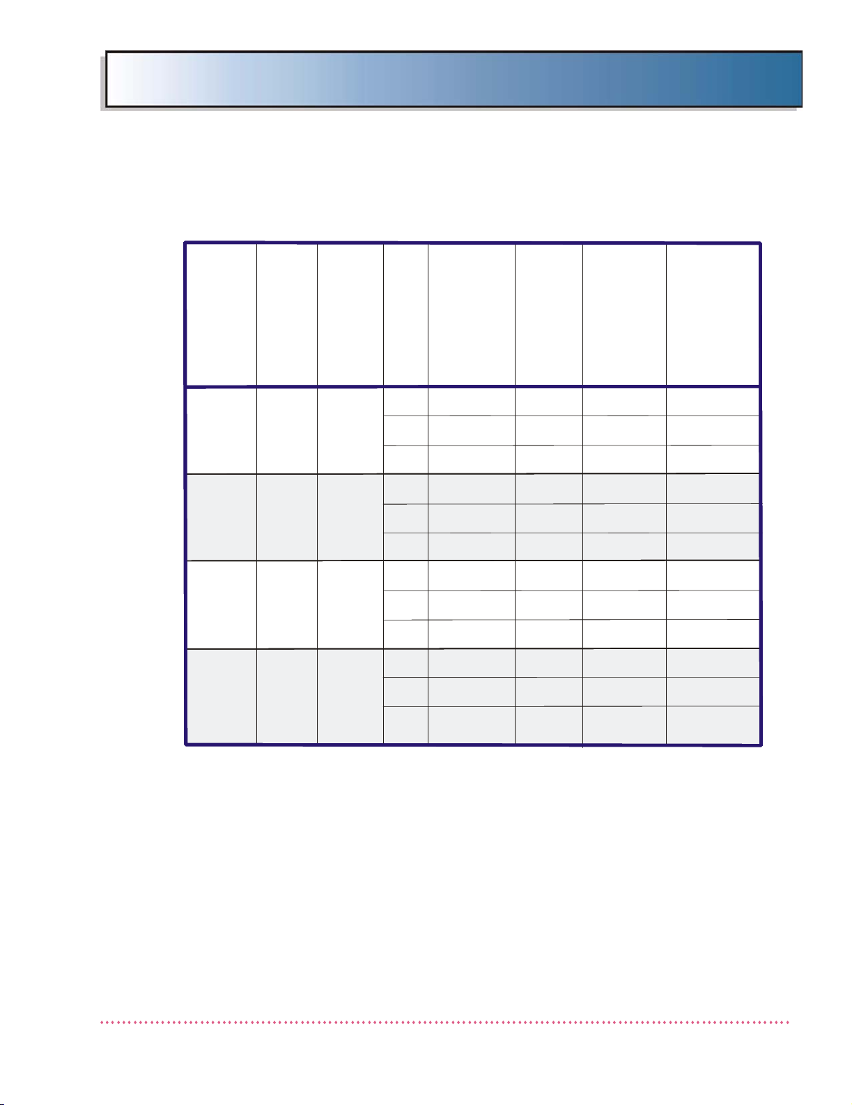
SYSTEM CONFIGURATIONS
The tables below show model numbers of components in each type of HF Series
X-ray Generator system (hereinafter referred to as the "HF Series X-ray Generators").
Note: The X-Ray Control Models shown in the following
tables are not used if the HF generator system is integrated
with computed radiographic (CR) or digital radiographic (DR)
workstation computer (e.g., Agfa NX, Canon CXDI, etc.).
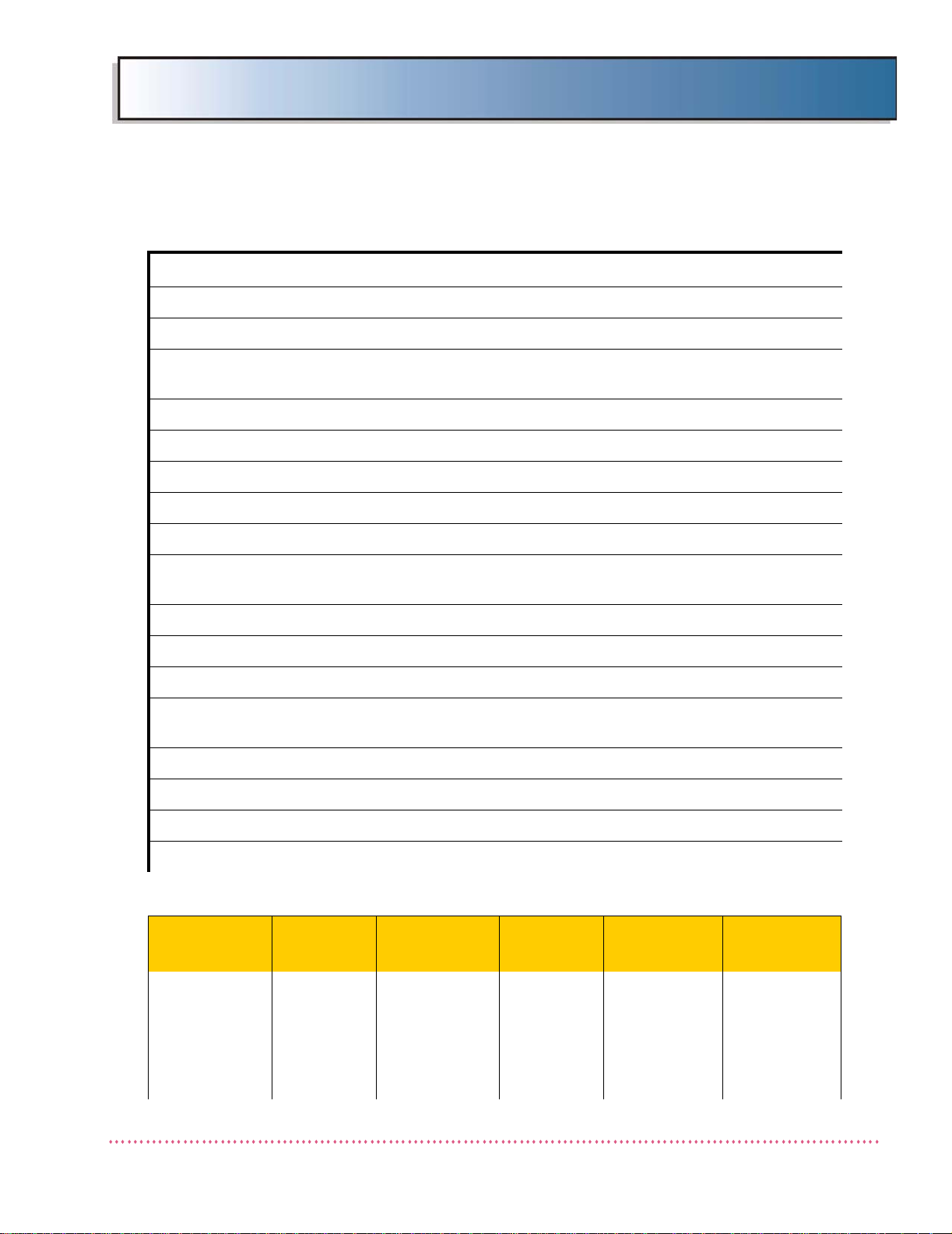
Single-Phase Model Generators
TM
SYSTEM
TYPE
ODYSSEY HF
32 kW
ODYSSEY HF
32 kW
ODYSSEY HF
40 kW
ODYSSEY HF
40 kW
Q-VISION HF
32 kW
Q-VISION HF
40 kW
SYSTEM
TYPE
CATALOG
NO.
QG-3200
QG-4000
QGV-32 QG-32 QG-32G
QGV-32-5 QG-32-5 QG-32G-5
QGV-40 QG-40 QG-40G
QGV-40-5 QG-40-5 QG-40G-5
Three-Phase Model Generators
CATALOG
NO.
SYSTEM
MODEL
QG-32 QG-32G QG-3200
QG-32-5 QG-32G-5 QG-3200
QG-40 QG-40G QG-4000
QG-40-5 QG-40G-5 QG-4000
SYSTEM
MODEL
GENERATOR
CABINET
MODEL
GENERATOR
CABINET
MODEL
X-RAY
CONTROL
MODEL*
QGV-32
QGV-40
X-RAY
CONTROL
MODEL
ODYSSEY
HF 32 kW
ODYSSEY
HF 40 kW
ODYSSEY
HF 50 kW
QG-3200
QG-4000
QG-5000
QG-32-2 QG-32G-2
QG-3200
QG-32-3 QG-32G-3
QG-40-2 QG-40G-2
QG-4000
QG-40-3 QG-40G-3
QG-50-2 QG-50G-2
QG-5000
QG-50 QG-50G
HF Series X-ray Generators - Service Manual Revision W
Quantum Medical Imaging 1-3
Page 18
Chapter 1 Specifications
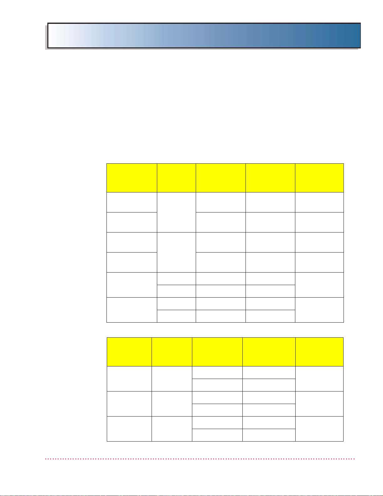
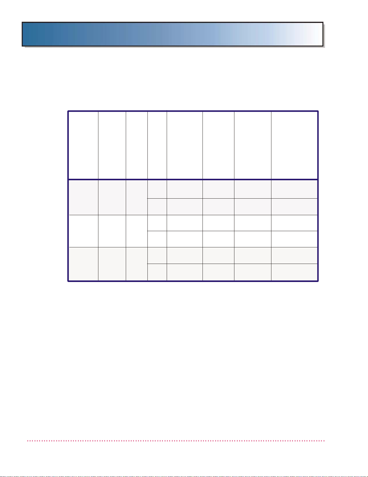
Three-Phase Model Generators
SYSTEM
TYPE
ODYSSEY
HF 65 kW
ODYSSEY
HF 80 kW
Q-VISION
HF 32 kW
Q-VISION
HF 40 kW
Q-VISION
HF 50 kW
Q-VISION
HF 65 kW
Q-VISION
HF 80 kW
CATALOG
NO.
QG-6500 QG-65 QG-65G QG-6500
QG-8000 QG-80 QG-80G QG-8000
QGV-32-2 QG-32-2 QG-32G-2
QGV-32-3 QG-32-3 QG-32G-3
QGV-40-2 QG-40-2 QG-40G-2
QGV-40-3 QG-40-3 QG-40G-3
QGV-50-2 QG-50-2 QG-50G-2
QGV-50 QG-50 QG-50G
QGV-65 QG-65 QG-65G QGV-65
QGV-80 QG-80 QG-80G QGV-80
SYSTEM
MODEL
GENERATOR
CABINET
MODEL
X-RAY
CONTROL
MODEL
QGV-32
QGV-40
QGV-50
STORED ENERGY (SE) Model Generators
SYSTEM
TYPE
ODYSSEY
HF 32 kW
ODYSSEY
HF 40 kW
ODYSSEY
HF 50 kW
Q-VISION
HF 32 kW
Q-VISION
HF 40 kW
Q-VISION
HF 50 kW
CATALOG
NO.
QG-3200-SE QG-32-SE QG-32G-SE QG-3200
QG-4000-SE QG-40-SE QG-40G-SE QG-4000
QG-5000-SE QG-50-SE QG-50G-SE QG-5000
QGV-32-SE QG-32-SE QG-32G-SE QGV-32-SE
QGV-40-SE QG-40-SE QG-40G-SE QGV-40-SE
QGV-50-SE QG-50-SE QG-50G-SE QGV-50-SE
SYSTEM
MODEL
GENERATOR
CABINET
MODEL
X-RAY
CONTROL
MODEL
Revision W HF Series X-ray Generators - Service Manual
1-4 Quantum Medical Imaging
Page 19

Chapter 1 Specifications
PHYSICAL SPECIFICATIONS
The following are physical specifications of the HF Series X-ray Generators:
GENERATOR CABINET SPECIFICATIONS
Width: 24.0 inches (609.6 mm)
Depth: 20.0 inches (508.0 mm)
Height: 34.7 inches (881.4 mm)
Weights:
Single-Phase (non-SE units): 298 lbs. (135.2 kg)
32, 40 and 50 kW Stored
Energy (SE) units: 431 lbs. (195.5 kg)
50, 65, 80 kW Three-Phase
units): 380 lbs. (712.4 kg) w/o internal HSS
388 lbs. (176.0 kg) w/internal HSS
OPERATOR CONTROL PANEL SPECIFICATIONS
Note: X-Ray Control Panels below are utilized with HF generator systems integrated with computed radiographic (CR) or
digital radiographic (DR) workstation computers (e.g., Agfa
NX, Canon CXDI, etc.).
The Q-VISION all-in-one operator control is not powered from the generator cabinet; it requires a separate 100-240 VAC, 3A power input.
ODYSSEY HF Control Panel:
Width: 17.9 inches (454.7 mm)
Depth: 12.25 inches (311.2 mm)
Height (without pedestal): 3.3 inches (83.8 mm)
Height (with pedestal): 36.5 inches (927.4 mm)
Weight (without pedestal): 5 lbs. (2.3 kg)
Weight (with pedestal): 25 lbs. (11.3 kg)
Q-VISION HF Control Panel:
Width: 18.7 inches (476.0 mm)
Depth (without stand): 1.9 inches (49.0 mm)
Depth (with stand): 7.125 inches (181.0 mm)
Height: 14.4 inches (365.0 mm)
Weight: 13 lbs. (5.9 kg)
SYSTEM SPECIFICATIONS
System Compatibility: Compatible with all Quantum Medical
Tube Compatibility: Toshiba Models E7239X, E7242X, E7252X,
Imaging tube stands, overhead tube
cranes, radiographic tables and wall stands
E7254X, E7255X, E7813X, E7869X
Varian Models RAD-8, RAD-13, RAD-14,
RAD-21, RAD-44, RAD-56, RAD-60,
RAD-68, RAD-74, RAD-92, A192, A272,
A292
HF Series X-ray Generators - Service Manual Revision W
Quantum Medical Imaging 1-5
Page 20

Chapter 1 Specifications
Collimators: Huestis Manual, Model 150MC
Note: The HF Series radiographic systems are compatible with any
automatic collimating system that provides an isolated normally open switch that closes when the Automatic Collimation System presents an “EXPOSURE READY” mode to the
control; they are also compatible with any beam limiting
device that complies with 21 CFR Subchapter J intended for
radiographic equipment.
POWER REQUIREMENTS
Dunlee Models PX 1302, PX 1429, PX 1436,
PX 1312, DU 309, DA 1092, MX100
replacement tube for GE Radiographic
Systems
(For tube types not listed, consult factory.)
Huestis Automatic, Model 150PBL
Huestis Selectable, Model 150A,
Progeny Linear MC150 (Manual)
Progeny Linear II and Linear IV
(Automatic)
In order to assure the proper operation of our equipment and subsequently, the production of high-qua lity radiographs, it is es se ntial that all pow er r e q u irements, as sp ec if ied in
the tables that follow, are suitably met by the facility in which the equipment is installed.
This includes usage of the proper size conductor between distribution transformer and disconnect switch, connection to a supply transformer of sufficient capacity (specified in
terms of KVA), insuring the AC input voltage tolerance meets specification (±5% or ±10%
depending on model), and voltage regulation of 5% at full load is maintained. All wiring
and grounding at the installation site must be in accordance with applicable National Electric Code (NEC) and/or local electrical codes.
THe generator requires a 3-phase "Y" connection, measured line-to-line, balanced to
earth or neutral. The "Y" connection can be 4-wire (L1, L2, L3, Neutral) and GND or
3-wire (L1, L2, L3) and GND. The 4-wire connection may be required by local electrical code and in connection where a roughly balanced 3-phase source exists (e.g.,
when using a delta-to-Y transformer).
Note that failure to comply with the above requirements not only may result in
improper generator operation and/or performance, but it will also void the warranty,
as the warranty is exclusive of the following conditions:
• "Failure of customer to prepare the site or provide power requirements or
operating environmental conditions in compliance with any applicable
instructions or recommendations of QMI.
• "Failure of customer to provide the proper incoming power required to support
the equipment in accordance with the recommendation of QMI.
• "Improper or extraordinary use of the Product, improper maintenance of the
Product, or failure to comply with any applicable instructions or
recommendations of Quantum Medical Imaging, LLC.
Revision W HF Series X-ray Generators - Service Manual
1-6 Quantum Medical Imaging
Page 21

Chapter 1 Specifications
NOTE: All single-phase x-ray generator input ratings assume the use of a
single-phase distribution transformer. When utilizing two legs of a 3phase transformer, review the National Electrical Code and any applicable local electrical code(s) to ensure the correct rating distribution
transformer (in terms of KVA) is used to assure line stability. This
configuration would require an increase in the overall power (KVA) of
the distribution transformer, depending on whether the input line
transformer is Wye or Delta type. Under no circumstances should a
Delta type transformer be used for input power to a 3-phase generator.
SINGLE-PHASE X-RAY GENERATORS
Non-Stored Energy Single-phase x-ray genera tors require three-wire line inputs in
either of the following two configurations:
• one hot wire, one neutral wire, and one earth ground wire
• two hot wires and one earth ground.
Refer to Table 1-1 for power requirements of single-phase (non-stored energy)
HF Series Generators.
25 kW Single Phase (Model QG-25)
Line Voltage: 208-260 VAC (±5%), 100 Amps, 50/60 Hz
Momentary Current: 200 Amps (@208VAC)
Long Term Current: less than 1.0 Amp
Mode of Operation: Intermittent operation
25 kW Single Phase (Model QG-25-5)*
Line Voltage: 380 - 480 VAC (±10%), 60 Amps, 50/60 Hz
Momentary Current: 110 Amps @ 415 VAC
Long Term Current: less than 1.0 Amp
Mode of Operation: Intermittent operation
32 kW Single Phase (Model QG-32)
Line Voltage: 208-260 VAC (±5%), 120 Amps, 50/60 Hz
Momentary Current: 240 Amps (@208VAC)
Long Term Current: less than 1.0 Amp
Mode of Operation: Intermittent operation
32 kW Single Phase (Model QG-32-5)*
Line Voltage: 380 - 480 VAC (±10%), 75 Amps, 50/60 Hz
Momentary Current: 140 Amps @ 415 VAC
Long Term Current: less than 1.0 Amp
Mode of Operation: Intermittent operation
HF Series X-ray Generators - Service Manual Revision W
Quantum Medical Imaging 1-7
Page 22

Chapter 1 Specifications
40 kW Single Phase (Model QG-40)
Line Voltage: 208-260 VAC (±5%), 150 Amps, 50/60 Hz
Momentary Current: 300 Amps (@208VAC)
Long Term Current: less than 1.0 Amp
Mode of Operation: Intermittent operation
40 kW Single Phase (Model QG-40-5)*
Line Voltage: 380-480 VAC (±10%), 100 Amps, 50/60 Hz
Momentary Current: 170 Amps @ 415 VAC
Long Term Current: less than 1.0 Amp
Mode of Operation: Intermittent operation
32 kW Single Phase, Stored Energy
Line Voltage: 105-130 (±10%), 10 Amps, 50/60 Hz
Momentary Current: 13 Amps @ 115 VAC
Long Term Current: less than 1.0 Amp
Mode of Operation: Intermittent operation
40 kW Single Phase, Stored Energy
Line Voltage: 105-130 (±10%), 10 Amps, 50/60 Hz
Momentary Current: 13 Amps @ 115 VAC
Long Term Current: less than 1.0 Amp
Mode of Operation: Intermittent operation
50 kW Single Phase, Stored Energy
Line Voltage: 105-130 (±10%), 10 Amps, 50/60 Hz
Momentary Current: 13 Amps @ 115 VAC
Long Term Current: less than 1.0 Amp
Mode of Operation: Intermittent operation
210-250 VAC (±10%), 10 Amps, 50/60 Hz
7 Amps @ 230 VAC
210-250 VAC (±10%), 10 Amps, 50/60 Hz
7 Amps @ 230 VAC
210-250 VAC (±10%), 10 Amps, 50/60 Hz
7 Amps @ 230 VAC
Note: Models QG-25-5, QG-32-5, and QG-40-5 are not UL classified.
Revision W HF Series X-ray Generators - Service Manual
1-8 Quantum Medical Imaging
Page 23

Chapter 1 Specifications
THREE-PHASE X-RAY GENERATORS
Three-phase x-ray generators require three "hot" wires and one earth ground
wire. Refer to Tables 1-2 and 1-3 for power requirements of three-phase HF
Series Generators.
32 kW Three Phase (Model QG-32-2)
Line Voltage: 208-240 VAC (±5%), 70 Amps, 50/60 Hz
Momentary Current: 140 Amps (@220 VAC)
Long Term Current: less than 1.0 Amp
Mode of Operation: Intermittent operation
32 kW Three Phase (Model QG-32-3)
Line Voltage: 380-480 VAC (±10%), 60 Amps, 50/60 Hz
Momentary Current: 117 Amps (@440 VAC)
Long Term Current: less than 1.0 Amp
Mode of Operation: Intermittent operation
40 kW Three Phase (Model QG-40-2)
Line Voltage: 208-240 VAC (±5%), 85 Amps, 50/60 Hz
Momentary Current: 170 Amps (@220 VAC)
Long Term Current: less than 1.0 Amp
Mode of Operation: Intermittent operation
40 kW Three Phase (Model QG-40-3)
Line Voltage: 380-480 VAC (±10%), 60 Amps, 50/60 Hz
Momentary Current: 125 Amps (@440 VAC)
Long Term Current: less than 1.0 Amp
Mode of Operation: Intermittent operation
50 kW Three Phase (Model QG-50-2)
Line Voltage: 208-240 VAC (±5%), 110 Amps, 50/60 Hz
Momentary Current: 220 Amps (@220 VAC)
Long Term Current: less than 1.0 Amp
Mode of Operation: Intermittent operation
50 kW Three Phase (Model QG-50-3)
Line Voltage: 380-480 VAC (±10%), 80 Amps, 50/60 Hz
Momentary Current: 144 Amps (@440 VAC)
Long Term Current: less than 1.0 Amp
Mode of Operation: Intermittent operation
HF Series X-ray Generators - Service Manual Revision W
Quantum Medical Imaging 1-9
Page 24

Chapter 1 Specifications
65 kW Three Phase (Model QG-65)
Line Voltage: 380-480 VAC (±10%), 90 Amps, 50/60 Hz
Momentary Current: 190 Amps (@440 VAC)
Long Term Current: less than 1.0 Amp
Mode of Operation: Intermittent operation
80 kW Three Phase (Model QG-80)
Line Voltage: 380-480 VAC (±10%), 100 Amps, 50/60 Hz
Momentary Current: 200 Amps (@440 VAC)
Long Term Current: less than 1.0 Amp
Mode of Operation: Intermittent operation
HIGH-SPEED STARTER POWER REQUIREMENTS
A High-Speed Starter (HSS) unit is optional on Models QG-40 and
QG-50, and is standard equipment on Models QG-65 and QG-80.
The external HSS (QG-HSS) configuration requires a separate 200 - 240 VAC, 20A
line input. Note that a separate 200- 240 VAC line input is
erators equipped with Internal High Speed Starter (Q-HSS) configuration.
not required
on gen-
Revision W HF Series X-ray Generators - Service Manual
1-10 Quantum Medical Imaging
Page 25

Chapter 1 Specifications
QG-25
QG-32
QG-40
GENERATOR
MODEL NO.
MAX. POWER
OUTPUT (kW)
NOMINAL LINE
VOLTAG E (VAC)
DISCONNECT
TO GENE R ATO R
15 FT. (5 M) M A X .
*SERVICE
RATING
*RECOMMENDED
DISTR IBU T IO N
TRANSFORMER
CAPACITY
MAX. INPUT LINE
RESISTANCE
(AT FULL-LOAD
RMS)
NOTE: All installations must meet the requirements of local electrical codes.
The above values are recommended as typical (unless otherwise specified).
*
1.
±5%)
Line Regulation: 5% at full load.
7. Ground wire size is 4 AWG.
8. Specifications are subject to change.
9. Specifications for single-phase “stored en ergy” Models QG-20-SE, QG-32-SE,
QG-40-SE and QG-50-SE are as follows:
105-130 VAC (±10%), 10 Amps, 50/60 Hz
210-250 VAC (±10%), 10 Amps, 50/60 Hz
All wire must be copper.
2. Actual wire size depends on power quality and distance between mains power
and the generator.
3. All wiring and grounding must be in accordance with National
Electric Code (NFPA #70) or local electrical codes.
4. The disconnect switch must be located within reach of the operator.
5. Input Voltage: 208-257 ( VAC 50/60 Hz (configured at time of installation).
6.
QG-250
QG-320,
QG-3200,
QGV-32
QG-400,
QG-4000,
QGV-40
GENERATOR
CATALOG NO.
208
25
32
40
240
208
240
208
240
#4 AWG
#4 AWG
#2 AWG
#2 AWG
#1 AWG
#1 AWG
100 AMPS
80 AMPS
120 AMPS
100 AMPS
150 AMPS
120 AMPS
30 KVA
30 KVA
40 KVA
40 KVA
50 KVA
50 KVA
0.06 OHMS
0.08 OHMS
0.04 OHMS
0.05 OHMS
0.035 OHMS
0.04 OHMS
Table 1-1. HF Series Generators -
Electrical Wiring Requirement s (208 - 260 VAC Single-Phase Input Units)
HF Series X-ray Generators - Service Manual Revision W
Quantum Medical Imaging 1-11
Page 26

Chapter 1 Specifications
*NOTE: All installations must meet the requirements of local electrical codes.
The above values are recommended as typical (unless otherwise specified).
*
1.
Input Voltage: 380-480 (±10%) VAC 50/60 Hz (configured at time of installation)
. Ground wire size is 4 AWG.
7. Specifications are subject to change.
All wire must be copper.
2. Actual wire size depends on power quality and distance between mains power
and the generator.
3. All wiring and grounding must be in accordance with National
Electric Code (NFPA #70) or local electrical codes.
4. The disconnect switch must be located within reach of the operator.
5. .
6
GENERATOR
MODEL NO.
MAX. POWER
OUTPUT (kW)
NOMINAL LINE
VOLTAGE (VAC)
DISCONNECT
TO GENERATOR
15 FT. (5 M) MAX.
*SERVICE
RATING
*RECOMMENDED
DISTRIBUTION
TRANSFORMER
CAP ACITY
MAX. INPUT LINE
RESISTANCE
(A T F U L L-LOAD
RMS)
GENERATOR
CATALOG NO .
25
32
40
QG-25-5
QG-32-5
QG-40-5
QG-250-5
QG-320-5,
QG-3200-5,
QGV-32-5
QG-400-5,
QG-4000-5,
QGV-40-5
380
#6 AWG 60 AMPS
32 KVA
0.028 OHMS
415 #6 AWG 55 AMPS 32 KVA 0.028 OHMS
480 #6 AWG 40 AMPS 32 KVA 0.032 OHMS
380 #6 AWG 75 AMPS 40 KVA 0.024 OHMS
415 #6 AWG 70 AMPS 40 KVA 0.024 OHMS
480
#6 AWG 60 AMPS
40 KVA
0.028 OHMS
380 #4 A WG 100 AMPS 50 KVA 0.015 OHMS
415
#4 AWG 90 AMPS
50 KVA
0.020 OHMS
480
#6 AWG 70 AMPS
50 KVA
0.024 OHMS
Table 1-2. HF Series Generators -
Electrical Wiring Requirements (380 - 480 VAC Single-Phase Input Units)
Revision W HF Series X-ray Generators - Service Manual
1-12 Quantum Medical Imaging
Page 27
Chapter 1 Specifications
QG-32-3,
QG-40-3
QG-50
QG-65
QG-80
32
(QG-32
-3)
40
(QG-40-3)
50
65
80
G
E
N
E
R
A
T
O
R
M
O
D
E
L
N
O
.
MAX. POWER
O
UTPUT (kW)
N
O
M
I
N
A
L
L
I
N
E
V
O
L
T
A
G
E
(
V
A
C
)
DISCONNECT
TO GENERATOR
15 FT. (5 M) MAX.
*
S
E
R
V
I
C
E
R
A
T
I
N
G
*
R
E
C
O
M
M
E
N
D
E
D
D
I
S
T
R
I
B
U
T
I
O
N
T
R
A
N
S
F
O
R
M
E
R
C
A
P
A
C
I
T
Y
MAX. INPUT LINE
RESISTANCE
(AT FULL-LO AD RMS)
380#6 AWG60 AMP
S
50 KV
A
0.23 OHMS380#4 AWG80 AMPS65 KVA0.17 OHMS380#4 AWG90 AMPS80 KVA0.12 OHMS380#4 AWG100 AMPS100 KVA0.10 OHMS440#6 AWG60 AMPS50 KVA0.33 OHMS440#6 AWG80 AMPS65 KVA0.20 OHMS440#4 AWG90 AMPS80 KVA0.17 OHMS440#4 AW
G
100 AMP
S
100 KVA
0.14 OHMS
480#6 AWG50 AMPS50 KVA0.4 OHMS480#6 AWG75 AMPS65 KVA0.24 OHMS480#4 AWG90 AMPS80 KVA0.19 OHMS480
#4 AWG100 AMPS100 KVA0.16 OHM
S
QG-320,
QG-3200,
QGV
-32-3,
QG-400,
QG-4000,
QG
V-40-3
QG-500,
Q
G-5000,
Q
GV-50
QG-6500,
QGV-65
QG-8000,
QGV-80
G
E
N
E
R
A
T
O
R
C
A
T
A
L
O
G
N
O
.
*NOTE: All installations must meet the requirements of local electrical codes.
The above values are recommended as typical (unless otherwise specified).
*
1.
Input Voltage: 380-480 (±10%) VAC 50/60 Hz (configured at time of installation)
. Voltage is three-phase Y-configuration, measured line-to-line, balanced to earth
ground. (Note: Additional Neutral wire may be used if required by local electrical code.)
7. Ground wire size is 4 AWG.
8. Specifications are subject to change.
All wire must be copper.
2. Actual wire size depends on power quality and distance between mains power
and the generator.
3. All wiring and grounding must be in accordance with National
Electric Code (NFPA #70) or local electrical codes.
4. The disconnect switch must be located within reach of the operator.
5. .
6
Table 1-3. HF Series Generators - Electrical Wiring Requirements
(380-480 VAC Three-Phase Input Units)
HF Series X-ray Generators - Service Manual Revision W
Quantum Medical Imaging 1-13
Page 28
Chapter 1 Specifications
QG-32-2
QG-40-2
QG-50-2
208
32
40
50
240
208
240
208
240
#6 AWG
#6 AWG
#4 AWG
#6 AWG
#4 AWG
#4 AWG
70 AMPS
60 AMPS
90 AMPS
70 AMPS
110 AMPS
90 AMPS
40 KVA
40 KVA
50 KVA
50 KVA
65 KVA
65 KVA
0.026 OHMS
0.023 OHMS
0.017 OHMS
0.024 OHMS
0.014 OHMS
0.016 OHMS
GENERATOR
MODEL NO.
MAX. POWER
OUTPUT (kW)
NOMINAL LINE
VOLTAGE (VAC)
DISCONNECT
TO GENERATOR
15 FT. (5 M) MAX.
*SERVICE
RATING
*RECOMMENDED
DISTRIBUTION
TRANSFORMER
CAPACITY
MAX. INPUT LINE
RESISTANCE
(AT FULL-LOAD
RMS)
QG-320,
QG-3200,
QGV-32-2
QG-400,
QG-4000,
QGV-40-2
QG-500,
QG-5000,
QGV-50-2
GENERATOR
CATALOG NO.
*NOTE: All installations must meet the requirements of local electrical codes.
The above values are recommended as typical (unless otherwise specified).
*
1.
Input Voltage: 208-257 (±5%) VAC 50/60 Hz (configured at time of installation)
. Voltage is three-phase Y-configuration, measured line-to-line, balanced to earth
ground. (Note: Additional Neutral wire may be used if required by local electrical code.)
Line Regulation: 5% at full load.
8. Ground wire size is 4 AWG.
9. Specifications are subject to change.
All wire must be copper.
2. Actual wire size depends on power quality and distance between mains power
and the generator.
3. All wiring and grounding must be in accordance with National
Electric Code (NFPA #70) or local electrical codes.
4. The disconnect switch must be located within reach of the operator.
5. .
6
7.
Table 1-4. HF Series Generators -
Electrical Wiring Requirements (208-240 VAC Three-Phase Input Units)
Revision W HF Series X-ray Generators - Service Manual
1-14 Quantum Medical Imaging
Page 29
Chapter 1 Specifications
GENERATOR AUXILIARY POWER SUPPLIES
The HF Series X-ray Generator supplies the following supply voltages for powering
X-ray room equipment:
• 24 VDC, 1.5A
• 24 VAC, 150W (collimator lamp not to exceed 150W)
• 115 VAC, 3A
NOTE: The above voltage outputs are not to be used as power
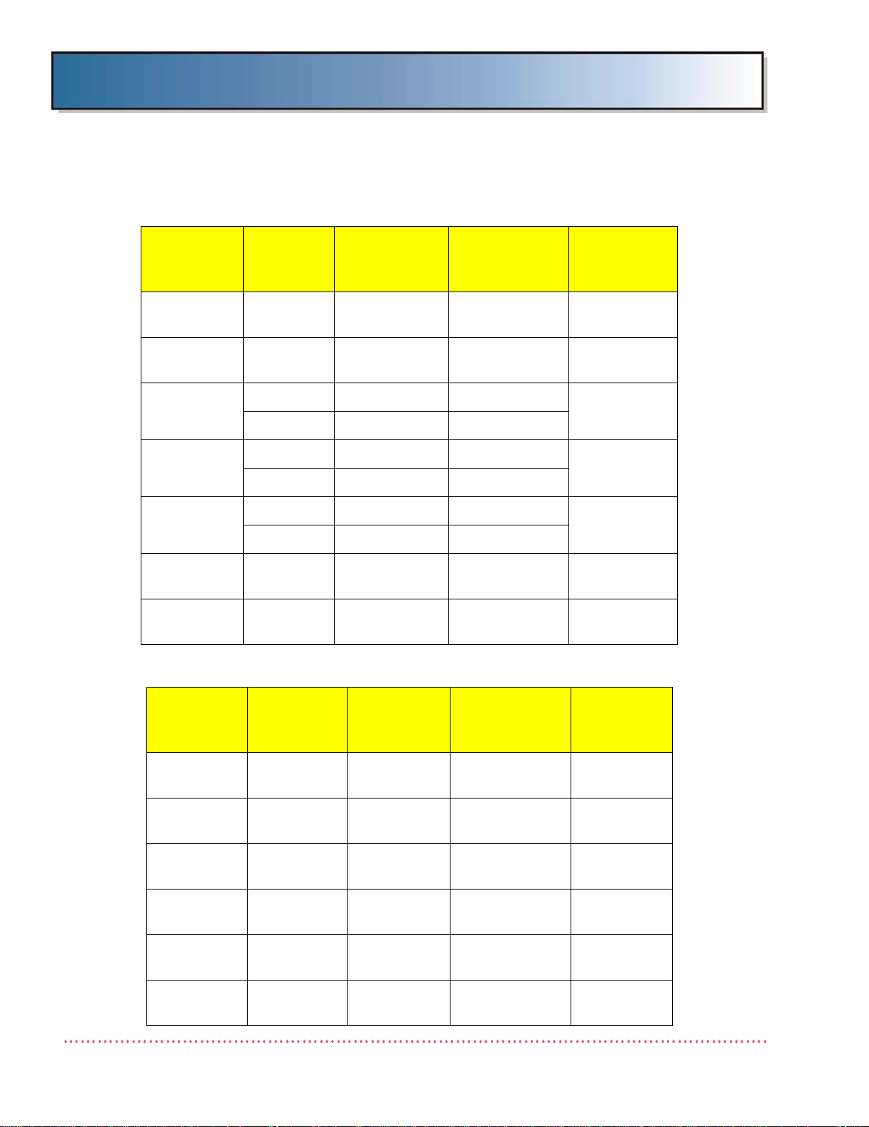
PERFORMANCE SPECIFICATIONS
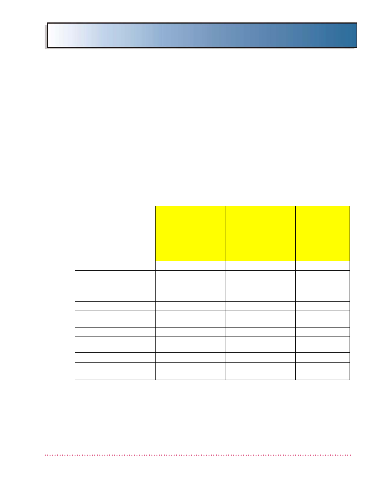
Table 1-5 provides performance specifications of single-phase (non-stored
energy) HF Series Generators.
Table 1-5. HF Series Single-Phase Generator Performance Specifications
sources for collimator lamps or for inductive loads (e.g.,
motorized tables, solenoids, etc.)
Cat. No.
N/A
QG-3200,
QGV-32
Models
N/A
QG-32,
QG-32-5
Maximum kW N/A 32 40
mA Stations;
Small Focus (S)
Large Focus (L)
kVp Range (kVp) N/A 40-125 40-125
kVp increments (kVp/step) N/A 1.0 1.0
150 kVp option N/A Yes Yes
Time Range (sec.)* N/A 0.001 - 6.3 0.001 - 6.3
Minimum Exposure Time
(sec.)
mAs Range†
High-Speed Starter
Ripple Voltage (output) N/A 5% 5%
* Time measured at 75% of the peak kVp waveform
NOTE: AEC TECHNIQUES SHOULD HAVE EXPOSURE TIMES EXCEEDING 8
MILLISECONDS.
†
mAs is tube dependent
N/A
N/A 0.001 0.001
N/A 0.025-600 0.025-600
N/A No No
25S, 75S, 150S
100L, 200L, 250L,
320L, 400L, 500L
Cat. No.
QG-4000,
QGV-40
Models
QG-40,
QG-40-5
25S, 75S, 150S
100L, 200L,
250L, 320L,
400L, 500L
HF Series X-ray Generators - Service Manual Revision W
Quantum Medical Imaging 1-15
Page 30
Chapter 1 Specifications
Refer to Table 1-6 for performance specifications of single-phase stored energy (SE) HF
Series Generators.
Table 1-6. HF Series Single-Phase STORED ENERGY Generator Performance Specifications
Cat. No.
N/A
QG-3200-SE,
QGV-32-SE
Model QG-32-SE
N/A
(STORED
ENERGY)
Maximum kW N/A 32 40 50
mA Stations;
Small Focus (S)
Large Focus (L) N/A
kVp Range (kVp) N/A 40-125 40-125 40-125
kVp increments
(kVp/step)
150 kVp optional? N/A No No No
Time Range
(sec.)*
Minimum Expo-
sure Time (sec.)*
mAs Range
High-Speed Starter
Ripple Voltage
(output)
N/A 1.0 1.0 1.0
N/A 0.001 - 6.3 0.001 - 6.3 0.001 - 6.3
N/A 0.001 0.001 0.001
N/A 0.025-400 0.025-500 0.025-500
N/A No No No
N/A 5% 5% 5%
25S, 50S, 75S, 150S
100L, 160L, 200L,
250L, 320L, 400L
Cat. No.
QG-4000-SE,
QGV-40-SE
Model QG-40-SE
(STORED
ENERGY)
25S, 50S, 75S, 150S
100L, 200L, 250L,
320L, 400L, 500L
Cat. No.
QG-5000-SE,
QGV-50-SE
Model QG-50-SE
(STORED
ENERGY)
25S, 50S, 75S,
150S
100L, 200L, 250L,
320L, 400L, 500L,
600L
* Maximum exposure time is a function of kV and mAs settings and the age of the
batteries; Time measured at 75% of the peak kVp waveform
NOTE: AEC TECHNIQUES SHOULD HAVE EXPOSURE TIMES EXCEEDING 8
MILLISECONDS.
mAs is tube dependent; the generator may not reach maximum mAs due t o tube type.
In AEC mode, the mAs is limited to 600.
Revision W HF Series X-ray Generators - Service Manual
1-16 Quantum Medical Imaging
Page 31

Chapter 1 Specifications
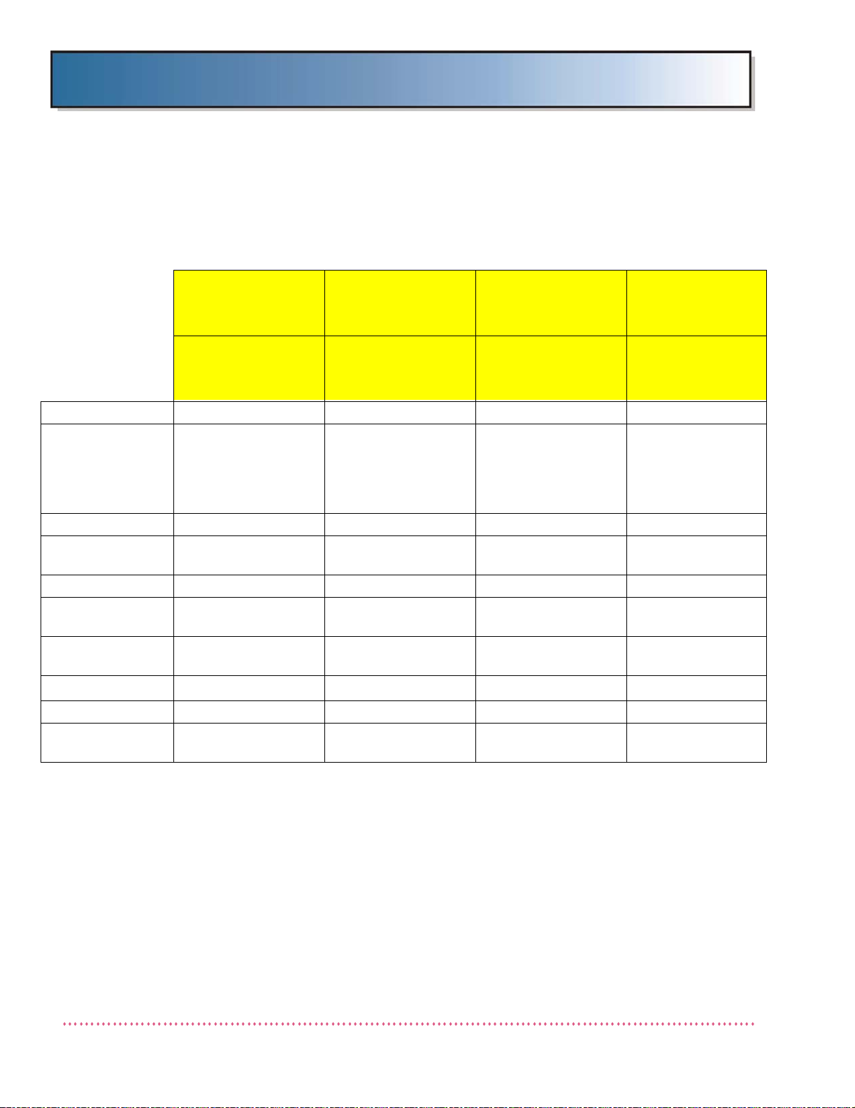
Refer to Table 1-7 for performance specifications of three-phase HF Series Generators.
Table 1-7. HF Series Three-Phase Generator Performance Specifications
Cat. No.
QG-3200-2,
QG-3200-3
QGV-32-2,
QGV-32-3
Model
Model QG-32-2,
QG-32-3
Maximum kW 32 40 50 65 80
mA Stations;
Small Focus (S)
Large Focus (L)
kVp Range
(kVp) 40-125
kVp increments
(kVp/step)
150 kVp
optional?
Time Range
(sec.)*
Minimum Exposure Time (sec.)
mAs Range† 0.025-600 0.025-600 0.025-800 0.025-800 0.025-800
High-Speed
Starter
Ripple Voltage
(output)
25S, 75S, 150S
100L, 200L,
250L, 320L,
400L, 500L
1.0 1.0 1.0 1.0 1.0
Yes Yes Yes Standard Standard
0.001 - 6.3 0.001 - 6.3 0.001 - 6.3 0.001 - 6.3 0.001 - 6.3
0.001 0.001 0.001 0.001 0.001
No Option Option Yes Yes
5% 5% 5% 5% 5%
Cat. No.
QG-4000-2,
QG-4000-3
QGV-40-2,
QGV-40-3
Model
Model QG-40-2,
QG-40-3
25S, 75S, 150S
100L, 200L,
250L, 320L,
400L, 500L
40-125
(40-150 with
QG-150 option)
Cat. No.
QG-5000-2,
QG-5000-3
QGV-50,
QGV-50-2
Model
QG-50-2,
QG-50
25S, 75S, 150S
100L, 200L,
320L, 400L,
500L, 650L
40-125
(40-150 with
QG-150 option)
Cat. No.
QG-6500,
QGV-65
Model
Model QG-65
25S, 75S, 150S
100L, 200L,
320L, 400L,
500L, 650L, 800
40-150 40-150
25S, 75S, 150S
Cat. No.
QG-8000,
QGV-80
Model
Model QG-80
100L, 200L,
320L, 400L,
500L, 650L,
800
* Time measured at 75% of the p eak kVp waveform
NOTE: AEC TECHNIQUES SHOULD HAVE EXPOSURE TIMES EXCEEDING 8
MILLISECONDS.
†
mAs is tube dependent; the generator may not reach maximum mAs
due to tube type. In AEC mode, the mAs is limited to 600.
High-Speed Starter Duty Cycle: do no t to exceed two activations
within any one minute period
HF Series X-ray Generators - Service Manual Revision W
Quantum Medical Imaging 1-17
Page 32

Chapter 1 Specifications
Accuracy Specifications
kVp Accuracy: kVp = ± ( 4.0% kV )
mA Accuracy: mA = ± ( 5.0% mA + 1 mA )
Time Accuracy:
mAs Accuracy:
mAs = ± ( 5.0% mAs + 0.5 mAs )
time = ± ( 2.0% time + 1 msec. )
time = ± ( 1.0% time + 1 msec. )
time = ± ( 0.5% time + 1 msec. )
Table 1-8. Accuracy Specifications
Revision W HF Series X-ray Generators - Service Manual
1-18 Quantum Medical Imaging
Page 33

Chapter 1 Specifications
SYSTEM OPTIONS
The following lists the available options for HF Series X-Ray Generators. Note that
some options, such as QG-150 and Q-HSS, may only be used on certain generator
models (refer to Tables 1-5 through 1-7 for compatibility):
• R80-HS: Exposure Hand Switch and R80-FS Foot Switch
• QG-PDL: Operator Control Panel Pedestal Mount (used with ODYSSEY
control panel)
• QG-WM: Operator Control Panel Wall Mount (used with ODYSSEY control
panel)
• QGV-WM: Operator Control Panel Wall Mount (used with Q-VISION control
panel)
• QG-150: 150 kV High Voltage Transformer (standard equipment on Models
QG-65 and QG-80)
• Q-HSS: Internal High (Dual) Speed Starter Unit (standard equipment on
Models QG-65 and QG-80
• Q-Connect: Enables ethernet connection to a PC computer using Quantum’s
"QBus" network integration software; required on systems utilizing a touchscreen operator control panel
• QG-28VPS: Internally mounted Auxiliary +28 VDC/8A Power Supply (only
available with three-phase input generators)
• QG-TOMO: Provides interface for operation with Siemens and Pausch
tomographic systems (not available with Q-VISION HF Series OCP’s)
• TechVision: Supplementary x-ray control panel, mounts on tube support
device. Refer to the TechVision Remote Control Panel Service and
Operator’s Manuals for complete installation and operation instructions.
NOTE: The use of ACCESSORY equipment not complying with the
equivalent safety requireme nts of this equipment may lead to
a reduced level of safety of the resulting system. Consideration relating to the choice shall include:
-use of the accessory in the PATIENT VICINITY
-evidence that the safety certification of the ACCESSORY has
been performed in accordance with the appropriate IEC 601-1
and/or IEC 601-1-1 harmonized national standard.
SYSTEM OPERATING ENVIRONMENT
Ambient Temperature: +10°C to +40°C
Relative Humidity: 30 to 75%, non-condensing
Atmospheric Pressure: 700 hPa to 1060 hPa
Typical Heat Output of
Generator Cabinet: 3600 BTU per hour
Typical Heat Output of
operator control panel (OCP): 130 BTU per hour
HF Series X-ray Generators - Service Manual Revision W
Quantum Medical Imaging 1-19
Page 34

Chapter 1 Specifications
NOTE: The above calculations are typical, based upon average usage.
Air circulation around the electronic cabinet must be provided.
This includes the sides, back, front and top of cabinet.
NON-OPERATING ENVIRONMENT
Ambient Temperature: -18°C to +70°C
Relative Humidity: 20 to 95%, non-condensing
Atmospheric Pressure: 500 hPa to 1060 hPa
Figure 1-1. HF Series X-ray Generator Cabinet Dimensions
Revision W HF Series X-ray Generators - Service Manual
1-20 Quantum Medical Imaging
Page 35

Chapter 1 Specifications
Figure 1-2. Odyssey HF Series X-ray Generator Operator Control
Panel Dimensions
HF Series X-ray Generators - Service Manual Revision W
Quantum Medical Imaging 1-21
Page 36

Chapter 1 Specifications
18.7
(476.0)
14.4
(365.0)
7.125
(181.0)
Figure 1-3. Q-VISION HF Series X-Ray Generator Operator Control
Panel Dimensions
Revision W HF Series X-ray Generators - Service Manual
1-22 Quantum Medical Imaging
Page 37

Chapter
2
ASSEMBLY &
INSTALLATION
2-1
Page 38

2-2
Page 39

Chapter 2 Assembly & Installation
OVERVIEW
This chapter provides procedures for installing the HF Series x-ray generator, from
pre-installation guidelines to final system inspection prior to operational readiness.
These procedures should be reviewed carefully before beginning the actual installation. Preparing the X-r ay generator f or operation require s completion of the following
tasks:
• Installing the X-ray generator cabinet
• Installing the Operator Control Panel (OCP)
• Making the Electrical Cable Connections
•Power-up
• Calibrating the generator
• Inspecting the system
• Verifying programmed techniques
WARNING! Equipment installation and servicing
procedures should be performed by properly
trained and qualified service personnel only.
PRE-INSTALLATION GUIDELINES
While site planning is the customer's responsibility, the following are recommended guidelines.
Verify Equipment Location
In radiology site preparation, it is essential to verify the location and space
allocated for the equipment is sufficient. See Figures 1-1 through 1-3 for HF
Series x-ray generator dimensions. The room plan should show the following
for the equipment:
• All working and parked positions
• Overall dimensions
• Total equipment weights and power outputs
• Structural mounting and attachment methods
Ensure sufficient air circulation space is provided between the rear side of
Generator Cabinet and wall (4.0" min.). The floor where the generator is
installed should be flat and approximately level (minor shimming is acceptable) and capable of supporting a load of 500 lbs. (226.8 kg).
If the generator is equipped with the "Q-Connect option" (ethernet adapter
for connection to Q-VISION or for integration with a Digital Radiographic System), the associated computer monitor functions as the generator operator
control panel (OCP). If the workstation is qualified to standard UL 60950/IEC
HF Series X-ray Generators - Service Manual Revision W
Quantum Medical Imaging 2-3
Page 40

Chapter 2 Assembly & Installation
2.5 m
1.5 m
1.5 m
1.5 m
60950 for Information Technology Equipment, the workstation must be
placed outside the radius of the patient environment, shown in Figure 2-1.
Only devices conforming to UL 60601-1/IEC 60601-1 may be placed within
this environment. Consult with the user of the system when determining the
location for the workstation computer; consider all areas the patient may
access, including the room entrance and/or exit, when establishing the
patient environment.
Figure 2-1. Patient Environment
Revision W HF Series X-ray Generators - Service Manual
2-4 Quantum Medical Imaging
Page 41

Chapter 2 Assembly & Installation
NOTE
Examine all cartons an d cr a t es
carefully at time
of delivery. If
damage is apparent, have del i very driver write a
"Damaged Shipment Note" on
copies of freight
bill, sign it, and
file appropriate
carrier claim.
Should you discove r co nc e aled
damage, immediately notify the
transporting
age nt and ask
for an
"Inspection of
Damage". Carrier
will not accept
concealed damage claim if filed
after 15 days
from date of
receipt of merchandise.
Electrical Requirements
In addition to providing for the physical requirements of the equipment,
it is also vital to prepare for the power requirements. Refer to Chapter
1, SPECIFICATIONS for model-dependent power specifications. This
information should be used to prepare system wiring and cabling.
UNPACKING
The HF Series x-ray generator is shipped in a single crate. To unpack, proceed as follows:
1. Remove packing list and use it as a guide to open the remaining cartons.
Do not dispose of packing material until packing list is matched with
actual parts received. Should there be a shortage or damage, notify
Quantum Medical Imaging, LLC.’s customer service department immediately . The manufacturer is relieved of any responsibility for damage during shipment after unit is picked up by the carrier.
HF Series X-ray Generators - Service Manual Revision W
Quantum Medical Imaging 2-5
WARNING! The X-ray generator cabinet can
weigh as much as 430 lbs. (195 kg), depending on configuration. Use lifting straps and
hoist or other suitable lifting device to transport generator. The H.V. Tank weighs
approximately 100 lbs. and requires two persons to lift.
2. Remove the Generator Cabinet from its crate (lifting straps and hoist or
other suitable lifting device is recommended).
3. Using a hand truck from the rear side of the cabinet, lift the generator
and place it as close to its final installation location as possible.
WARNING! When unpacking the generator;
keep upright at all times. Verify there is no
damage caused during shipping, with no
apparent oil leakage from H.V. Tank; check that
the tank lid and oil plug (in tank lid) are secure.
4. Locate the OCP and Pedestal (optional) or Wall Mount Bracket (optional) and
place on the side (not applicable on Q-VISION equipped systems or with integrated systems (e.g., Agfa, Canon, etc.).
Page 42

Chapter 2 Assembly & Installation
INSTALLATION
The following paragraphs provide information necessary for installing the Generator
Cabinet and Operator Control Panel (OCP), including all required external equipment
cable connections with the X-ray generator.
CAUTION! This equipment contains electrostatic
sensitive devices. Observe proper grounding precautions before handling components or printed
circuit boards.
REQUIRED TOOLS AND MATERIALS
The following lists the tools and materials required to perform the procedures
included in this chapter:
• Hoist with lifting straps (or other suitable lifting device)
• Tape measure
• Standard hand tools
• Drill bit, suitable size for installing floor mounting hardware
• Bubble level
• Various wiring connectors and cable ties
GENERATOR CABINET SETUP
1. Loosen six (6) phillips head screws (3 each on left and right sides of cabinet)
and remove three (3) phillips head screws (in lower front side) securing generator cabinet cover to generator chassis (see Figure 2-1a). Grasp cover on
each side, lift up slightly and remove.
Figure 2-1a. Generator Cabinet Cover Screw Locations
Revision W HF Series X-ray Generators - Service Manual
2-6 Quantum Medical Imaging
Page 43

Chapter 2 Assembly & Installation
WARNING! Approximately 200 VDC is present on
each battery tray. This voltage is live even when
generator cabinet power switch is set to OFF. Use
extreme caution when servicing battery tray(s).
2. On stored energy (SE) units, open the two (2) modular fuse holders located
on the front of each battery tr ay. Note that there are two pairs of fuses on 32
kW and 40 kW units, one pair for each battery tray.
3. If mounting generator to floor, mark locations of the four mounting holes on
floor in accordance with dimensions given in Figure 2-2. Drill four holes using
proper diameter drill bit (depending on mounting hardware used).
Figure 2-2. Generator Cabinet Mounting Hole Locations
4. Position the generator chassis in its mounting location and place a level on
flat horizontal surface of chassis. If chassis is not level, add shim(s) below
generator as required until level.
5. After all cable connections that require access to the rear of the generator are
complete, secure cabinet to floor using 3/8" diameter mounting hardware
suitable for floor construction type.
HF Series X-ray Generators - Service Manual Revision W
Quantum Medical Imaging 2-7
Page 44

Chapter 2 Assembly & Installation
NOTE
STORED ENERGY
(SE) models can
operate between
105 and 130 VAC
and non-SE,
single-phase
models between
200 and 270
VAC. Refer to
Chapter 1, SPECIFICATIONS.
Transformer Line Tap Adjustment (Single Phase Non-SE Systems)
WARNING! Extreme care MUST be exercised to
ensure the safety of service or other personnel in
the area when working with live AC mains.
Proceed as follows:
1. Using a calibrated DVM, measure the AC input (mains) voltage (i.e., lineto-line or line-to-neutral, when applicable).
2. Verify that power to x-ray generator is disconnected.
3. Adjust transformer taps by relocating the leads on the top side of transformer terminal block TB2 to match the input line voltage as closely as
possible. Refer to Figure 2-3 for 208 - 260 VAC single-phase input line
tap configurations, and Figure 2-4 for 380 - 480 VAC single-phase input
line tap configurations.
Revision W HF Series X-ray Generators - Service Manual
2-8 Quantum Medical Imaging
Figure 2-3. Single-Phase 208 - 260 VAC Single-Phase Input
AC Transformer Line Tap Connections
Page 45

Chapter 2 Assembly & Installation
Figure 2-4. Single-Phase 380 - 480 VAC Single-Phase Input
AC Transformer Line Tap Connections
4. For single-phase non-SE models, it is necessary to insure that the line
resistance meets the maximum allowed as stated in Chapter 1, SPECIFICATIONS . If line resistance exceeds the specification, the gener ator must
be derated. Refer to Chapter 3, CALIBRATION for derating instructions.
5. Verify Line Monitor Board A8 "line input jumper" is configured correctly
based on the installation site’s measured line input voltage as follows:
a. For 208 - 260 VAC input models (QG-25, QG-32 and QG-40), refer to
Line Monitor Board A8 (AY40-022T1) Test Point/Jumper Location Diagram in Chapter 6, DIAGRAMS and, if necessary, set "line input"
jumpers to match the line input supply voltage (i.e., 208 - 260 VAC,
three "240" jumpers are installed). Also, for 208 - 260 V AC line input
configurations, fuses A8F1 and A8F3 should be 1/2A.
b. For 380 - 480 VAC input models (QG-25-5, QG-32-5 and QG-40-5),
refer to Line Monitor Board A8 (AY40-022T2) Test Point/Jumper Location Diagram in Chapter 6, DIAGRAMS and, if necessary, set "line
input" jumpers to match the line input supply voltage (i.e., for 342403 VAC input, install jumper"380"; for 404-459 VAC input, install
jumper "430"; for 460-528 VAC input, install jumper "480"). Also,
for 380 - 480 VAC line input configurations, fuses A8F1 and A8F3
should be 1/4A.
HF Series X-ray Generators - Service Manual Revision W
Quantum Medical Imaging 2-9
Page 46

Chapter 2 Assembly & Installation
Transformer Line Tap Adjustment (Single Phase SE Systems)
WARNING! Extreme care MUST be exercised to
ensure the safety of service or other personnel in
the area when working with live AC mains.
1. Using a calibrated DVM, measure the AC input (mains) voltage (i.e., lineto-line or line-to-neutral, when applicable).
2. Verify that power to x-ray generator is disconnected.
3. Adjust transformer taps by relocating the leads on the left side of transformer terminal block TB1 to match the input line voltage as closely as
possible. Refer to Figure 2-5 for STORED ENERGY (SE) input line tap
configurations.
6. Refer to Line Monitor/Battery Charger Board A8 (AY40-028T) Test Point/
Jumper Location Diagram in Chapter 6, DIAGRAMS a nd verify "line input"
jumpers are configured to match the line input supply voltage (115 or
230 VAC). Also, for 115 VAC line input configurations, fuses A8F5 and
A8F7 should be 2A; for 230 VAC line input configurations, these fuses
should be 1A.
Figure 2-5. STORED ENERGY Input AC Transformer Line Tap Connections
Revision W HF Series X-ray Generators - Service Manual
2-10 Quantum Medical Imaging
Page 47

Chapter 2 Assembly & Installation
198 VAC
208 VAC
220 VAC
240 VAC
198 VAC
208 VAC
220 VAC
240 VAC
198 VAC
208 VAC
220 VAC
240 VAC
PHASE A PHASE B
LA40-056 REV. C
234523452345
380 VAC
415 VAC
440 VAC
480 VAC
380 VAC
415 VAC
440 VAC
480 VAC
380 VAC
415 VAC
440 VAC
480 VAC
PHASE A
PHASE B
LA40-033 REV. F
56785
6785678
380-480 VAC LINE INPUT CONFIGURATION
208-240 VAC LINE INPUT CONFIGURATION
TA P ADJUSTMENT
LEADS
WARNING! Extreme care MUST be exercised to
ensure the safety of service or other personnel in
the area when working with live AC mains.
Proceed as follows:
1. Using a calibrated DVM, measure the AC input (mains) voltage (i.e., lineto-line).
2. Verify that power to x-ray generator is disconnected.
3. Adjust transformer taps by relocating the leads on the top side of transformer terminal block TB2 to match the input line voltage as closely as
possible. Refer to Figure 2-6 for input line tap configurations.
HF Series X-ray Generators - Service Manual Revision W
Quantum Medical Imaging 2-11
Figure 2-6. Three-Phase Input AC Transformer Line Tap Connections
4. For three-phase models, it is necessary to insure that the line resistance
meets maximum allowed as stated in Chapter 1, SPECIFICATIONS. If
line resistance exceeds the specification, the generator must be derated.
Refer to Chapter 3, CALIBRATION for derating instructions.
Page 48

Chapter 2 Assembly & Installation
5. On Line Monitor Board A8 (part number AY40-053S2 used on 380-480
VAC line input configuration, part number AY40-053S3 used on 208-240
VAC line input configuration), verify 380/430/480 jumper is configured
correctly based on incoming line voltage measurement as follows (see
Line Monitor Board A8 Chapter 6, DIAGRAMS):
AC INPUT VOLTAGE (MEASURED) JUMPER POSITION
342-403 VAC 380
404-459 VAC 430
460-528 VAC 480
198-252 VAC 240 (3 jumpers)
AC Input (Mains) Connection
WARNING! Verify incoming power supply (mains
disconnect) is turned OFF and all mains cables are
de-energized before connecting to the generator.
All electrical connections must be made in compliance with local and/or NEC
requirements. The generator is factory configured to accept line input specified when the order was placed. However, if it is necessary to change the
generator line input configuration, refer to the previous procedure entitled
"Transformer Line Tap Adjustment".
Non-STORED ENERGY (SE) version generators require a mains disconnect
box (with switch) before the x-ray generator (refer to your local code). This
switch should be within reach of the operator. A separate earth ground, #6
AWG insulated wire, must be installed. This wire must be the only wire connected to the generator ground terminal.
Revision W HF Series X-ray Generators - Service Manual
2-12 Quantum Medical Imaging
Page 49

Chapter 2 Assembly & Installation
GENERATOR
CHASSIS
LINE INPUT
CABLE CLAMP
(TYPICAL)
TERMINAL
BLOCK TB1
GROUND
LUG
For non-SE generators, connect AC input cable as follows:
1. Mount cable clamp (included with system) to the hole on the lower right
or left side of generator cabinet chassis (see Figure 2-7).
Figure 2-7. Line Input Cable Clamp Installation
2. Route the AC input cable through cable clamp to Terminal Block TB1 and
tighten cable clamp.
3. On single-phase systems:
a. Connect ground wire to ground lug mounted on rear wall of genera-
tor chassis, to the left of terminal block TB1 (see Figure 2-8).
Figure 2-8. Single-Phase Systems - Ground Lug and Terminal
Block TB1 Locations
HF Series X-ray Generators - Service Manual Revision W
Quantum Medical Imaging 2-13
Page 50

Chapter 2 Assembly & Installation
GROUND
LUG
TERMINAL
BLOCK TB1
b. Connect mains line and neutral wires to TB1 term i n al s L1 an d L2 ,
respectively. Do not turn mains power on at this time.
4. On three-phase systems:
a. Connect Phase A, B and C wires to TB1 terminals L1 through L3,
respectively. Do not turn mains power on at this time. (See
Figure 2-9).
Figure 2-9. Ground Lug and Terminal Block TB1 Locations
b. If available, connect Neutral wire to TB1 terminal L4 (N). (Neutral
connection may be required; check local electrical code.)
5. On STORED ENERGY (SE) type generators, the battery tray fuse(s) are
shipped in the non-inserted position to minimize battery discharge and
high voltage hazards. With fuse in holder, close the fuse holder(s). The
SE system can be plugged into a standard switched 115/230 VAC
grounded receptacle. The switch controlling the receptacle should be
within reach of the operator control console. For 115 V AC installations, a
25-foot power cord with a hospital-grade plug is factory pre-wired to the
generator. For 230 VAC installations, a 25-foot "HAR" power cord is factory pre-wired to the generator.
If power cord is replaced, ensure that impedance between the protective
contact in the mains plug and any accessible metal part which is protectively earthed does not exceed 0.1 Ohms.
Revision W HF Series X-ray Generators - Service Manual
2-14 Quantum Medical Imaging
Page 51

Chapter 2 Assembly & Installation
HV TANK (TOP VIEW)
PRESSURE RELIEF SCREW:
AT TIME OF INSTALLATION,
TURN SCREW COUNTERCLOCKWISE TWO (2) TURNS
AND LEAVE IN THIS
POSITION.
High Voltage (H.V.) Tank
The HF Series X-ray Generator is shipped with the H.V. Tank installed at the
factory . Locate the Pressure R elief Screw on the top side of the H.V. T ank near
the front right corner (see Figure 2-10). To permit venting, loosen screw two
(2) turns (counterclockwise) and leave in this position.
Figure 2-10. H.V. Tank (Top View)
The following instructions are provided should it be necessary to install the
H.V. Tank. When installing the H.V. Tank, keep it upright at all times. See
Figure 2-11 and proceed as follows:
WARNING! After completing the following procedure, double-check the H.V. Tank wiring connections to make sure they are correctly connected.
Incorrect wiring can cause damage to the generator. Ensure that ground wires are connected.
HF Series X-ray Generators - Service Manual Revision W
Quantum Medical Imaging 2-15
Page 52

Chapter 2 Assembly & Installation
CAUTION! The H.V. Tank weighs approximately
92 lbs. (41.7 kg). Lift with proper assistance.
1. Loosen four (4) screws securing the clear plastic high-voltage acrylic protection panel from the generator chassis and remove panel.
2. Position H.V. Tank on Tank Mounting Brackets so mounting holes in tank
align with those in mounting brackets. Secure tank to brack ets using four
(4) 1/4-20 x 3/4" hex head screws, flat washers and lock washers.
3. Connect H.V. Tank cable terminal PC1 to Power Module A19 IGBT lower
right terminal. Tighten screw securely.
4. Connect H.V. Tank cable terminal PC2 to right terminal lug on Capacitor
C7. Tighten nut securely.
5. Connect H.V. Tank cable terminal PA1 to left terminal lug on Capacitor C4.
Tighten nut securely.
6. Connect H.V. Tank cable terminal PA2 to Power Module A18 lower left
IGBT terminal. Tighten screw securely.
7. Locate ground wires for H.V. Tank (yellow/green) and securely fasten to
H.V. Tank ground stud (GND) using 8/32 kep nut (provided on stud).
8. Insert plug A17P1 (16-pin plug on Cable Assembly AY51-017) into connector A17J1 on the H.V. Tank and tighten plug securely.
9. Re-install the clear plastic high-voltage protection panel on the generator
chassis and re-tighten four (4) mounting screws.
Revision W HF Series X-ray Generators - Service Manual
2-16 Quantum Medical Imaging
Page 53

Chapter 2 Assembly & Installation
Figure 2-11. H.V. Tank Connections
HF Series X-ray Generators - Service Manual Revision W
Quantum Medical Imaging 2-17
Page 54

Chapter 2 Assembly & Installation
BEFORE INSERTING
CABLE, LOOSEN
SET SCREW
COAT WITH
INSULATING
COMPOUND
BEFORE
INSERTING
1
TIGHTEN RING NUT
ONTO RECEPT ACLE
2
FULLY TIGHTEN
SET SCREW
3
High Voltage Cables
It is important that these instructions be followed for the proper installation
of the High Voltage Cable terminals into the tube housing and H.V. Tank
receptacles. Use proper handling to ensure cable terminals and receptacles
are clean and free of moisture. Connect High Voltage Cables, respecting
proper anode and cathode polarity, as follows:
Figure 2-12. High Voltage Cable Connection to H.V. Tank
Revision W HF Series X-ray Generators - Service Manual
2-18 Quantum Medical Imaging
Page 55

Chapter 2 Assembly & Installation
ROTOR
CABLE
ALL OTHER
CABLES
GENERATOR CABINET (VIEWED FROM REAR)
HIGH
VOLTAGE
CABLES
CAUTION! When routing the High Voltage Cables
into the generator cabinet through the access
openings, the anode and cathode cable must each
be routed separate from all other system cables,
except the Tube Rotor Cable, as shown in Figure
2-13. Doing so will reduce the possibility of electromagnetic noise coupling and subsequent degradation of system performance.
Figure 2-13. Routing High Voltage Cables into the Generator Cabinet
HF Series X-ray Generators - Service Manual Revision W
Quantum Medical Imaging 2-19
Page 56

Chapter 2 Assembly & Installation
1. If not already done so, assemble onto the High Voltage Cable end a cable
retaining nut, grounding washer and strain relief (see Figure 2-14).
Ensure the 10-32 x 1/4" locking screw is turned out so as not to interfere
with engagement.
Figure 2-14. High Voltage Cable Assembly (Typical)
2. The High Voltage Cable terminals and tube housing and H.V. Tank receptacles must be clean and dry. Be sure compression gaskets are in place
on the cable terminal.
3. To insure proper locking and grounding of the cable sheath, do not omit
the compression gasket on the cable terminal, as it is necessary for
proper contact between cable nut and flare.
4. Insert the cable terminal into the receptacle socket (watch the nipple on
the terminal to ensure correct positioning of the contact pins). Coat the
entire surface of the cable terminal insulator with insulating
compound (supplied with cables) using clean, dry plastic spoon
or wooden stick. Do not use fingers. Fully cover the entire surface
with a heavy coat (approximately 1/16" to 1/8"). Build a pyramid at the
tip of the terminal with the height of the compound even with the contact
ends.
5. With terminal key aligned with receptacle key way, insert the cable terminal into receptacle until all excess compound has oozed out. Make sure
the contact pins are engaged in the holes in the socket insulator. Wipe
off any excess compound.
6. Tighten the cable nut while holding the cable firmly in place. Re-tighten
after calibration as some loosening may take place after the housing has
been heated and cooled. With cable nut properly tightened, secure with
10-32 x 1/4" locking screw.
Revision W HF Series X-ray Generators - Service Manual
2-20 Quantum Medical Imaging
Page 57

Chapter 2 Assembly & Installation
24VAC
24 VAC
CHASSISGND.24VD
C
24V RTN
SPARE
15V RTN
15 VD
C
CHASSIS
GND
.
COL RDY
SLO-BLO
250 VAC
8 AMP
220VAC
110VAC
DOOR INTERLOCK
TERMINAL BLOCK TB6
TUBESTAND
TERMINAL
BLOCK TB2
COLLIMATOR
CONNECTIONS
TERMINAL BLOCK TB1
EXPOSURE
HOLD
CONNECTIONS
(AUTO COLL.)
X-RAY ON LIGHT
TERMINAL BLOC K TB5
JP1 INSTALLED
ON SYSTEMS WITH
MANUAL COLLIMATOR
JP2 INSTALLED
ON SYSTEMS WITH
NON-BUCKY TABLE
RECEPTOR
JP3 INSTALLED
ON SYSTEMS WITH
NON-BUCKY WALL
RECEPTOR
TABLE BUCKY POWER
TERMINAL BLOCK TB3
WALL STAND BUCKY POWER
TERMINAL BLOCK TB4
MIDWEST BUCKY SWITCHES
(SEE T ABLE /WALL BUCKY
CONNECTION INSTRUCTIONS)
TUBE ROTOR
BOOST VOLTAGE
JUMPER
(REV. R AND
HIGHER BOARDS
ONLY)
INTERFACE BOARD SETTINGS & CONNECTIONS
The generator’s Inte rface Board A9 pr ovides the means for ele ctrically connecting
external system components, such as collimators, tube stands, buckies, etc., and
verifying the correct Rotor Boost Voltage setting (non-high speed starter systems
only). Figure 2-15 shows connection locations on a typical non-digital (filmbased) system Interface Board; Figure 2-16 shows connection locations on a typical digital imaging system Interface Board.
Figure 2-15. Non-Digital System Interface Board A9 - Connection Locations
HF Series X-ray Generators - Service Manual Revision W
Quantum Medical Imaging 2-21
Page 58

Chapter 2 Assembly & Installation
1
24VAC
24VAC
CH GND
24V
24V RTN
SPARE
COLL RDY
15V RTN
15V
GND
D2
D4
D7
D8
D12
D13
D14
K3
R11
R12
R16
R17
R19
TB5
D20
D19
F18
F19
F13
DOOR INTERLOCK
TERMINAL BLOCK TB6
TUBESTAND
TERMINAL
BLOCK TB2
COLLIMATOR
CONNECTIONS
TERMINAL BLOCK TB1
EXPOSURE
HOLD
CONNECTIONS
(AUTO COLL.)
X-RAY ON LIG HT
TERMINAL BLOCK TB5
TABLE BUCKY POWER
TERMINAL BLOCK TB3
TUBE ROTOR BOOST
VOLTAGE JUMPER
(REV. J AND HIGHER
BOARDS ONLY)
WALL STAND BUCKY POWER
TERMINAL BLOCK TB7
Figure 2-16. Digital System Interface Board A9 - Connection Locations
Door Interlock Switch Connection
To wire a door interlock circuit, remove jumper and connect door interlock
wires (supplied by installer) to terminal block TB6 pins 1 and 2 on Interface
Board A9 [(P/N AY40-023T/or AY40-061T on internal high-speed starter systems) or (AY40-034T/or A Y40-062T on internal high-speed starter systems)].
See Figures 2-15 or 2-16 for terminal board TB6 location. When the door is
closed, the circuit will be continuous (contacts closed).
"In Use" Light Switch Connection
To wire an "X-ray On" or "In-Use light", connect wires from light circuit (supplied by installer) to terminal board TB5 pins 1 and 2 on Interface Board A9
[(P/N AY40-023T/or AY40-061T on internal high-speed starter systems) or
(AY40-034T/or AY40-062T on internal high-speed starter systems)] (On
AY40-062T boards, pin 3 is not used). See Figures 2-15 or 2-16 for terminal
block TB5 location. When the X-ray generator is in either PREP or EXPOSE
states, the circuit will be continuous (contacts closed).
Revision W HF Series X-ray Generators - Service Manual
2-22 Quantum Medical Imaging
Page 59

Chapter 2 Assembly & Installation
P2-1 (+)
P2-2 (-)
OUTPUT
VOLTAGE
ADJ. POT.
Collimator Connections
Terminal block TB1 (see Figures 2-15 or 2-16 for terminal block TB1 location)
provides 24 VAC (TB1-1 and TB1-2) and chassis ground (TB1-3) outputs for
connection to a collimator. On systems equipped with a manual collimator,
verify jumper A9JP1 is installed; remove A9JP1 if system is equipped with an
automatic collimator.
Also available on terminal block TB2 is the COL RDY terminal (at TB2-4) for
connection to automatic collimator with "exposure hold" interlock (use CHASSIS GND terminal TB2-7 for return). Refer to collimator manual for specific
connection details.
Tube Stand/Peripheral Equipment Connections
Interface Board A9 Terminal block TB2 (see Figures 2-15 or 2-16 for terminal
board TB2 location) provides +28 VDC (TB2-1) and +28 VDC RTN (TB2-2)
terminals for connection of a tube stand power input cable, when applicable.
Maximum load current is 1.5A at these terminals.
Internal +28 VDC Power Supply Option (QG-28VPS)
If generator is equipped with +28 VDC Internal Power Supply Option
(QG-28VPS), see Figure 2-16a and connect the tubestand/wallstand’s power
supply input leads as follows:
1. Positive lead to terminal P2-1 (+) on power supply
2. Negative lead to terminal P2-2 (-) on power supply
Figure 2-16a. Internal +28 VDC Power Supply Option (QG-28VPS) Location
HF Series X-ray Generators - Service Manual Revision W
Quantum Medical Imaging 2-23
Page 60

Chapter 2 Assembly & Installation
The output of the +28 VDC Power Supply is adjusted depending on the type
of Quantum product it will supply power to, as indicated below:
Table 2-1a: Internal +28 VDC Power Supply Option (QG-28VPS) Adjustment
Quantum Product Type Adjust Power Supply Output To:
Model RS-580 Overhead Tube Crane +30 VDC
Model QV-800 Universal System +28 VDC
Model QW-420-T, QW-420-T-D Vertical
Tilting Wall Stand
When using the +28 VDC Power Supply Option to provide power for a Model
RS-580 Overhead Tube Crane, the +30 VDC output is intended for operating
the tube crane’s transverse and longitudinal electromagnetic locks (brakes).
Refer to the RS-580 Service Manual for connection instructions.
CAUTION! The Internal +28 VDC Power Supply
Option (QG-28VPS) is only available with 3-phase
generators, and is intended to supply power to a
single, external device.
Tube Rotor Boost Voltage Verification (Systems without High (Dual) Speed Starter Option)
Ensure Interface Board A9 [P/N A Y40-023T (non-digital systems, revision R or
later boards only)/AY40-023T1 (non-digital stored energy systems, r evision K
or later boards only)/AY40-034T (digital systems, revision J or later boards
only)] Tube Rotor Boost V oltage Jumper is configured correctly depending on
the type of tube the generator is being interfaced with according to table
below:
Table 2-1: Tube Rotor Boost Vol tage Jumper Setting
+28 VDC
TUBE TYPE
Toshiba E7252X, E7813X,
E7242X, E7239X
All others (220 VAC stator) Pins 2-3 220 VAC Stator
JUMPER
POSITION
Pins 1-2 100 VAC Stator
ROTOR BOOST VOLTAGE
SETTING
Revision W HF Series X-ray Generators - Service Manual
2-24 Quantum Medical Imaging
Page 61

Chapter 2 Assembly & Installation
RADIOGRAPHIC SYSTEM EQUIPMENT CONNECTIONS
The following paragraphs provide instructions for cable connections between the
HF Series x-ray generator and the x-ray tube, table, and wall bucky, as necessary.
Refer to Generator Interconnection Diagrams in Chapter 6, DIAGRAMS for additional guidance.
Ensure the generator is configured with the correct value rotor phase capacitor
C1 (on the Generator door) for tube installed in the system (refer to Table 2-2).
Table 2-2: Standard Single-Speed Rotor Phase Capacitor Configuration
Tube Type Rotor Phase Capacitors
E7239X, E7242X 25 uF
E7254X, E7255X, ALL VARIAN,
ALL DUNLEE (including MX100 Replacement for GE Radiographic System)
E7813X, E7252X 45 uF
Tube Rotor Cable (Systems without High (Dual) Speed Starter Option)
Route the X-ray Tube Rotor Cable AY51-014 through the middle cable access
opening located in the top rear wall of the generator chassis. Connect one
end of the cable to the appropriate terminals on Terminal Block TB1 on Rotor
Drive Board A10 (P/N AY40-013T) as shown in Figure 2-17. Connect the
opposite end to the X-ray tube’s terminal strip (refer to appropriate interconnection diagram in Chapter 6, DIAGRAMS for tube connections).
30 uF
HF Series X-ray Generators - Service Manual Revision W
Quantum Medical Imaging 2-25
Page 62

Chapter 2 Assembly & Installation
TERMINAL BLOCK TB1
POTENTIOMETER R20
TUBE CURRENT ADJ.
POTENTIOMETER R24
TUBE CURRENT ADJ.
1MAIN
2 PHASE
3 COMMON
4 NOT USED
5 NOT USED
6 GROUND
7TEMP
TERMINAL
SIGNAL
TEST POINT 7
ROTOR RUN
TEST POINT 10
+15 VDC
TEST POINT 4
PHASE
TEST POINT 1
COMMON
TEST POINT 2
MAIN
TEST POINT 3
AC RETURN
TEST POINT 13
60 VAC
TEST POINT 12
200 VAC
U3
TP3
R26
R15
R12
MOV4
MOV3
J3
R37
PD2
TB1
K2
D18
C14
R35
TP1
TP2
+
C16
Q10
U6
PD1
Q9
R46
J5
TP4
R20
R25
R24
D4
D5
+
C7
D7
D12
R36
R27
R19
Q6
J4
D8
TP15
U5 7 8
D15
C15
R41
Q8
TP14
R30
R29
R11
Q7
D17
R22
R45
TP7
TP10
D10
D1
TP8
U4
D3
Q5
R6
R9
D14
R3
Q3
C4
D6
D9
D11
C1
TP6
10W
R2
10W
R14
PD3
MOV2
C8
TP13
J1
TP12
Q1
MOV1
C6
Q4
C2
PD4
TP11
R4
C3
U1
Q2
U2
R10
D2
R8
R7
R5
TP9
TP5
R33
R32
R17
R16
7
1
1
3
B
CE
B
B
EEC
1
2
ECEBCBC
9
10
1
1
4
T2
T1 G
T1
T2
G
B
CE
9
Revision W HF Series X-ray Generators - Service Manual
2-26 Quantum Medical Imaging
Figure 2-17. Rotor Board AY40-013T Tube Rotor Cable Connections
Page 63

Chapter 2 Assembly & Installation
Tube Rotor Cable (Systems with AID External High Speed Starter QG-HSS Option Only)
Refer to Figure 2-18, the AID High Speed Starter installation manual and/or
the appropriate interconnection diagram in Chapter 6, DIAGRAMS for high
speed starter connections.
tems equipped with the externally-connected AID High Speed
Starter option.
1. Connect one end of X-ray Tube Rotor Cable AY51-032T to the appropriate
connector/terminals on AID High Speed Starter LC102 terminal block TS2
(see Figure 2-18).
2. Connect the opposite end to the X-ray tube’s terminal strip.
3. Route the X-ray Tube Rotor Cable AY51-033 (Toshiba tubes) through the
middle cable access opening located in the top rear wall of the generator
chassis.
4. Connect one end of the High Speed Starter Cable AY51-033 to the appropriate connector/terminals on AID High Speed Starter terminal strips TB1
and TB2 and connect to Cable Assembly AY51-032T (temperature sense
connector).
Note: This procedure applies only to sys-
5. Connect the opposite end of the High Speed Starter Cable AY51-033 to
connector J8 on Logic Board A1, AY40-006S.
6. Connect 220 VAC power input to High Speed Starter.
7 . The AID High Speed Starter was factory pre-configured for the x-ra y tube
supplied with the generator. Verify boost and brake settings are correct
according tube manufacturer’s data sheets (ref er to Table 2-3). Verify the
high speed starter is configured with the correct capacitors for the tube
used with the system: Toshiba E7252X and E7813X should be configured
for 45 uF. All other tube types require 30 uF.
HF Series X-ray Generators - Service Manual Revision W
Quantum Medical Imaging 2-27
Page 64

Chapter 2 Assembly & Installation
Table 2-3: AID High Speed Starter DIP Switch Settings
TUBE TYPE
TOSHIBA
E7813X,
E7252X
TOSHIBA
E7254X,
E7255X
VARIAN
(ALL 3 INCH
DIA.)
VARIAN
(ALL 4 INCH
DIA.)
START
VOLTAGE
(180 HZ)
220 VAC
(#6 tap*)
490 VAC (use
370 VAC tap
#10*)
320 VAC
(use 370 VAC
tap #10*)
450 VAC
(use 370 VAC
tap #10*)
RUN
VOLTAGE
(180 HZ)
60 VAC
(75 VAC #3
tap*)
165 VAC
(75 VAC #3
tap*)
100 VAC
(75 VAC #3
tap*)
100 VAC
(75 VAC #3
tap*)
HSS SWITCH
SW1 (BOOST
TIME)
1.2 seconds:
SW1-1 = OFF
SW1-2 = ON
SW1-3 = ON
SW1-4 = OFF
SW1-5 = OFF
2.0 seconds:
SW1-1 = OFF
SW1-2 = ON
SW1-3 = OFF
SW1-4 = ON
SW1-5 = OFF
1.0 seconds
SW1-1 = ON
SW1-2 = OFF
SW1-3 = ON
SW1-4 = OFF
SW1-5 = OFF
2.2 seconds
SW1-1 = ON
SW1-2 = ON
SW1-3 = OFF
SW1-4 = ON
SW1-5 = OFF
HSS SWITCH
SW2 (BRAKE
TIME)
2.0 seconds:
SW2-1 = OFF
SW2-2 = ON
SW2-3 = OFF
SW2-4 = ON
SW2-5 = OFF
2.0 seconds:
SW2-1 = OFF
SW2-2 = ON
SW2-3 = OFF
SW2-4 = ON
SW2-5 = OFF
2.0 seconds:
SW2-1 = OFF
SW2-2 = ON
SW2-3 = OFF
SW2-4 = ON
SW2-5 = OFF
2.0 seconds:
SW2-1 = OFF
SW2-2 = ON
SW2-3 = OFF
SW2-4 = ON
SW2-5 = OFF
Revision W HF Series X-ray Generators - Service Manual
2-28 Quantum Medical Imaging
Page 65

Chapter 2 Assembly & Installation
Figure 2-18. AID High Speed Starter Connections
HF Series X-ray Generators - Service Manual Revision W
Quantum Medical Imaging 2-29
Page 66

Chapter 2 Assembly & Installation
Tube Rotor Cable (Systems with Internal High Speed Starter QHSS Option Only)
The Q-HSS High Speed Starter is factory pre-configured for the x-ray tube
supplied with the generator and, with the exception of the Rotor Cable, does
not require any field connections or adjustments. Tables 2-3a and 2-3b are
provided in the event tube replacement is necessary or if the HSS Power
Driver Board AY40-036S needs replacement. The table indicates the proper
connections of the various transformer voltage inputs (380, 220, 120, 80, 60
and 0 VAC) to the HSS Driver Board at Termin al Block TB1 for each of the
compatible tubes used with t he generator.
Also, ensure the generator is configured with the correct value rotor capacitors for the installed tube as indicated in Table 2-3a.
Table 2-3a: Quantum High-Speed Starter Rotor Phase Capacitor Configuration
Tube Type Rotor Phase Capacitors
E7813X, E7252X, E7869X Install one (1) 40 uF cap (low speed), two (2) 12 uF in series
(high speed)
E7254X, all Varian, all
Dunlee (except MX100 GE
replacement, see below)
Dunlee MX100 Replacement for GE Radiographic
System
If not already connected, connect transformer input wires to HSS Driver
Board AY40-036S terminal block TB1 plug for corr ect tube type in ac cordance
with table below:
Table 2-3b: HSS Driver Board AY40-036S Boost and Run Voltage Requirements: Transformer
TUBE MODEL
TOSHIBA E7255,
E7254
Install one (1) 25 uF cap (low speed), two (2) 12 uF in series
(high speed)
Install one (1) 25 uF cap (low speed), two (2) 15 uF in series
(high speed)
Input Wires to Terminal Block Plug TB1
TB1-1 TB1-3 TB1-5 TB1-6 TB1-7
HIGH SPEED
BOOST
VOLTAGE
WIRE #5
(380 VAC)
LOW SPEED
BOOST
VOLTAGE
WIRE #4
(220 VAC)
HIGH SPEED
RUN
VOLTAGE
WIRE #3
(120 VAC)
LOW SPEED
RUN
VOLTAGE
WIRE #2A
(80 VAC)
COMMON
WIRE #1
(0 VAC)
TOSHIBA E7252,
E7813
WIRE #4
(220 VAC)
WIRE #3
(120 VAC)
WIRE #2A
(80 VAC)
WIRE #2
(60 VAC)
WIRE #1
(0 VAC)
Revision W HF Series X-ray Generators - Service Manual
2-30 Quantum Medical Imaging
Page 67

Chapter 2 Assembly & Installation
Table 2-3b: HSS Driver Board AY40-036S Boost and Run Voltage Requirements: Transformer
Input Wires to Terminal Block Plug TB1
TB1-1 TB1-3 TB1-5 TB1-6 TB1-7
TUBE MODEL
VARIAN RAD 92,
RAD 60, RAD 56,
RAD 44, A292,
A272;
DUNLEE DA 1092,
DU309, PX 1302,
PX 1312, PX 1429,
PX 1436
VARIAN RAD 21,
RAD 14, RAD 13,
A192;
TOSHIBA E7869X
DUNLEE MX100
Replacement for GE
HIGH SPEED
BOOST
VOLTAGE
WIRE #5
(380 VAC)
WIRE #5
(380 VAC)
LOW SPEED
BOOST
VOLTAGE
WIRE #4
(220 VAC)
WIRE #4
(220 VAC)
HIGH SPEED
RUN
VOLTAGE
WIRE #3
(120 VAC)
WIRE #2A
(80 VAC)
LOW SPEED
RUN
VOLTAGE
WIRE #2
(60 VAC)
WIRE #2
(60 VAC)
COMMON
WIRE #1
(0 VAC)
WIRE #1
(0 VAC)
NOTE 1: Stow unused WIRE #2 (60 VAC) or WIRE #2A (80 VAC) in unused terminal block
TB1-2 location.
NOTE 2: Terminal block location TB1-4 is not used.
Non-Overhead Tube Crane Rotor Cable Wiring Instructions
Refer to Figure 2-18a and the steps below to connect the Rotor Cable to the
HSS Driver Board x-ray tube on a system
Crane.
1. Route the X-ray Tube Rotor Cable from the tube through the middle cable
access opening located in the top rear wall of the generator chassis.
2. Connect the MAIN (BLK) conductor to terminal 1 on HSS Driver Board
A20A2 Terminal Block TB2.
3. Connect the PHASE (RED) conductor to terminal 3 on HSS Driver Board
A20A2 Terminal Block TB2.
4. C onnect the COMMON (WHT) conductor to terminal 6 on HSS Driver
Board A20A2 Terminal Block TB2.
5. Connect the TEMP SENSE (ORN) conductor to terminal 1 on HSS Driver
Board A20A2 Terminal Block TB4.
6. Connect the TEMP SENSE (GRN) conductor to terminal 2 on HSS Driver
Board A20A2 Terminal Block TB4.
not using
an Overhead Tube
HF Series X-ray Generators - Service Manual Revision W
Quantum Medical Imaging 2-31
Page 68

Chapter 2 Assembly & Installation
L4A
L5A
L5B
L4B
1
B
B
B
E
E
E
DANGER
HIGH VOLTAGE
HIGH VOLTAGE
DANGER
C17
C21
C27
C28
C29
C30
C33
C37
C42
C47
C49
C51
J1
J3
2
0
R5
R11
R13
R15
R16
R17
R18
R20
R26
R42
R43
R47
R50
R54
R55
R58
R60
TB1
TP1
TP2
TP6
TP8
TP10
U9
R2
R67
R68
R72
R71
R73
R28
D6
D11
D12
D14
D4
D31
D22
R63
R64
R66
C7
C6
C2
L4
L5
B
L
K
RED
W
H
T
O
R
N
G
R
N
R
O
T
O
R
C
A
B
L
E
A
2
0
A
2
T
B
2
A
2
0
A
2
T
B
4
H
S
S
D
R
I
V
E
R
B
O
A
R
D
A
2
0
A
2
(
A
Y
4
0
-
0
3
6
S
)
R
O
T
O
R
C
A
B
L
E
C
O
N
N
E
C
T
I
O
N
S
:
M
A
I
N
(
B
L
K
)
T
O
A
2
0
A
2
T
B
2
-
1
P
H
A
S
E
(
R
E
D
)
T
O
A
2
0
A
2
T
B
2
-
3
C
O
M
M
O
N
(
W
H
T
)
T
O
A
2
0
A
2
T
B
2
-
6
T
E
M
P
S
E
N
S
E
(
O
R
N
)
T
O
A
2
0
A
2
TB4
-
1
T
E
M
P
S
E
N
S
E
(
G
R
N
)
T
O
A
2
0
A
2
TB4
-
2
7. Connect the opposite end to the X-ray tube’s terminal strip.
Figure 2-18a. Non-Overhead Tube Crane System Rotor Cable Connections
Revision W HF Series X-ray Generators - Service Manual
2-32 Quantum Medical Imaging
Overhead Rotor Cable Wiring Instructions
Refer to Figure 2-18b and the steps below to connect the Rotor Cable to the
x-ray tube on a system using an Overhead Tube Cranes:
1. Route the X-ray Tube Rotor Cable from the tube through the middle cable
2. Connect the MAIN (BLK 0) conductor to terminal 1 on HSS Driver Board
3. Connect the PHASE (BLK 1) conductor to terminal 3 on HSS Driver Board
4. Connect the COMMON (BLK 2) conductor to terminal 6 on HSS Driver
access opening located in the top rear wall of the generator chassis.
A20A2 Te rminal Block TB2.
A20A2 Te rminal Block TB2.
Board A20A2 Terminal Block TB2.
Page 69

Chapter 2 Assembly & Installation
L4A
L5A
L5B
L4B
1
B
B
B
E
E
E
DANGER
HIGH VOLTAGE
HIGH VOLTAGE
DANGER
C17
C21
C27
C28
C29
C30
C33
C37
C42
C47
C49
C51
J1
J3
2
0
R5
R11
R13
R15
R16
R17
R18
R20
R26
R42
R43
R47
R50
R54
R55
R58
R60
TB1
TP1
TP2
TP6
TP8
TP10
U9
R2
R67
R68
R72
R71
R73
R28
D6
D11
D12
D14
D4
D31
D22
R63
R64
R66
C7
C6
C2
L4
L5
B
L
K
0
BLK 1
B
L
K
2
B
L
K
W
H
T
R
O
T
O
R
C
A
B
L
E
A
2
0
A
2
T
B
2
A
2
0
A
2
T
B
4
H
S
S
D
R
I
V
E
R
B
O
A
R
D
A
2
0
A
2
(
A
Y
4
0
-
0
3
6
S
)
R
O
T
O
R
/
T
E
M
P
CABL
E CON
NECTI
ONS
:
M
A
I
N
(
B
L
K
0
)
T
O A20
A
2TB2-
1
P
H
A
S
E
(
B
L
K
1) TO A20A2
TB2
-
3
C
O
M
M
O
N
(
B
L
K
2) T
O
A2
0
A2TB2
-
6
T
E
M
P
S
E
N
S
E
(
BLK) TO A
20A2T
B4-
1
T
E
M
P
S
E
N
S
E
(
WHT)
TO A2
0A2TB4-
2
T
U
B
E
T
E
MP
CAB
L
E
L
X
1
-
D
160
X
6
.
1
s
w
;3w
s
5. Connect the TEMP SENSE (BLK) conductor to terminal 1 on HSS Driver
Board A20A2 Terminal Block TB4.
6. Connect the TEMP SENSE (WHT) conductor to terminal 2 on HSS Driver
Board A20A2 Terminal Block TB4.
7. Connect the opposite end to the X-ray tube’s terminal strip.
HF Series X-ray Generators - Service Manual Revision W
Quantum Medical Imaging 2-33
Figure 2-18b. Overhead Tube Crane System Rotor Cable Connections
Page 70

Chapter 2 Assembly & Installation
Table/Wall Bucky Connections
Wall stand and/or table buckies are interconnected to the HF Series x-ray
generator via Interface Board A9, P/N AY40-023T terminal blocks A9TB4
(Wall Stand) and A9TB3 (Table) or Digital Interface Board AY40-034T terminal blocks A9TB7 (Wall Stand) and A9TB3 (Table) using 5-conductor, 18AWG
cable (P/N EL75-025), which is provided with the table and/or wall stand.
IMPORTANT! When interfacing to a 14" x 17"
Midwest table or wall bucky, switches A9SW1 or
A9SW2, respectively, must be set to the "M" position. For 14" x 36" Midwest, Progeny, or LF type
buckies, switches A9SW1 or A9SW2 must not be
set to the "M" position.
Refer to bucky manufacturer’s installation manual (provided with system) for
specific bucky wiring information and to Figures 2-15, 2-16, and in Chapter 6,
DIAGRAMS, Figures 6-6 through 6-9. Bucky cable entrance/exit is provided
through the access opening in the top rear panel of the generator chassis.
DO NOT route cables through an opening containing a High Voltage Cable
(see Figure 2-13). When connecting a table bucky, remove jumper JP2 on
Interface Board A9. When connecting a wall bucky, remove jumper JP3 on
Interface Board A9.
Table/Wall Ion Chamber Connections (AEC Option Only)
Systems equipped with standard type AEC (AEC Board AY40-031S):
If using a wall ion chamber, connect wall ion chamber cable to AEC Board
A11, P/N AY40-031S connector J2. If using a table ion chamber, connect
table ion chamber cable to AEC Board A11 connector J4. Table 2-4 shows
AID type ion chamber connector pin assignments. Route the ion chamber
cable(s) as necessary to exit through the access opening in top rear side of
generator chassis, and secure as required. DO NOT route through an opening containing a High Voltage Cable (see Figure 2-13).
Table 2-4: AID ICX-153 or ICX-1153 Ion Chamber 9-Pin Sub-D Connector Pin-Outs
9-PIN SUB-D
CONNECTOR PIN
1NONE
2 FIELD 2 SELECT
3 FIELD 1 SELECT
4RESET
5OUTPUT
6 FIELD 3 SELECT
7 NEGATIVE SUPPLY
8 POSITIVE SUPPLY
9GROUND
FUNCTION
Revision W HF Series X-ray Generators - Service Manual
2-34 Quantum Medical Imaging
Page 71

Chapter 2 Assembly & Installation
(Note: Perform ion chamber balance procedure in accordance with manufacturer’s instructions provided with chamber.)
Typically, when the HF Series x-ray generator is shipped with an AID ICX ion
chamber, the chamber jumpers are pre-set in the following configuration:
Table 2-5: AID ICX-153 or ICX-1153 Ion Chamber Jumper Configuration
JUMPER POSITION FUNCTION
61135A W1 1-2 & 3-4 LOW ACTIVE RESET
61135A W2, W3, W4 1-2 & 3-4 LOW ACTIVE FIELD SELECT
61135A W5, W6 1-2 & 3-4 A-B-C = 2-1-3
61135A W7 2-3 POSITIVE OUTPUT SIGNAL
CAUTION! The ion chamber must be electrically
isolated from the bucky to ensure proper AEC system performance.
For systems equipped with universal type AEC (AEC Board AY40-027S):
Up to four ion chambers can be used. Connect ion chambers as follows:
• Wall#1 ion chamber to A11J8
• Wall#2 ion chamber to A11J12
• Table ion chamber to A11J10
• Auxiliary ion chamber to A11J13
Note that to connect a Siemens ion chamber AEC cable to universal AEC
Board A11 requires an interface cable assembly AY51-061 for each chamber.
This cable assembly adapts the ion chamber connector to 9-pin D-Sub type
used on the AEC Board, and provides a separate 300 VDC wire f or connection
to A11TB1.
Route the ion chamber cable(s) as necessary to exit through the access opening in top rear side of generator chassis, and secure as required. DO NOT
route through an opening containing a High Voltage Cable (see Figure 2-13).
Interfacing to Canon Digital Radiographic Receptor (When Applicable)
The digital radiographic receptor is interconnected to the HF Series x-ray generator via Interface Board A9, P/N AY40-034T terminal blocks A9TB7 (Wall
Stand) and A9TB3 (Table), respectively, using 4-conductor, 18AWG cable.
Refer to the digital receptor manufacturer’s installation manual for more
detailed wiring instructions.
HF Series X-ray Generators - Service Manual Revision W
Quantum Medical Imaging 2-35
Page 72

Chapter 2 Assembly & Installation
Digital receptor cable entrance/exit is provided through the access opening in
the top rear panel of the generator chassis. DO NOT route signal cables
through an opening containing a High Volt age Cable (see Figure 2-13). When
connecting to a table digital receptor, remove jumper JP2 on Interface Board
A9. When connecting to wall digital receptor, remove jumper JP3 on Interface Bo ard A9.
Interfacing to CMT Digital Radiographic Receptor (When Applicable)
Refer to CMT digital receptor installation manual for detailed wiring instructions.
Interfacing to Siemens Ion Chambers (When Applicable)
Note: When interfacing the generator to a Siemens table/wall
ion chamber and a Quantum table/wall ion chamber (AID type),
only the Siemens ion chambers require the use of cable
assembly AY51-061. The Quantum table/wall ion chamber can
be connected directly to AEC Board A11 (AY40-027S) connector
J10 (TABLE) or J8 (WALL).
Interfacing of the HF Series x-ray generator to Siemens table and/or wall ion
chambers, such as in Siemens Tomography System, is facilitated using the
"universal" type AEC Board A11 (AY40-027S) located on the front side of the
generator cabinet PCB door. The VERTIX wall stand and MULTIX table ion
chambers are connected as shown in Figure 2-19. Note that cable assemblies
AY51-061 shown in the illustration should already be connected to both the
MULTIX table AEC cable EK14 and the VERTIX wall stand AEC cable. Any
additional ion chambers used with the system are connected as described in
"Table/Wall Ion Chamber Connections (AEC Option Only)" procedure included
in this chapter.
Figure 2-19. AEC Ion Chamber Connections (Siemens Tomography System)
Revision W HF Series X-ray Generators - Service Manual
2-36 Quantum Medical Imaging
Page 73

Chapter 2 Assembly & Installation
SECURE ONE ION
CHAMBER CABLE
CONNECTOR HERE
SECURE OTHER
ION CHAMBER
CABLE CONNECTOR
HERE
Secure the ion chamber cables to the PCB Door using cable ties as shown in
Figure 2-20.
HF Series X-ray Generators - Service Manual Revision W
Quantum Medical Imaging 2-37
Figure 2-20. Siemens Ion Chamber Cable Management
Interfacing to Siemens Tomography System (When Applicable)
The Siemens tomo interface cable (supplied with the Siemens system) has
attached to it at one end three plugs identified as "KK1B G1,G2 X10", "KK1B
G1,G2 X11" and "KK1B G1,G2 X12". Plugs "X10" (TABLE), "X11" (W ALL) and
"X12" (TOMO SWEEP TIME) will need to be cut off and the wire ends stripped
to allow connection to the universal AEC Board A11 (AY40-027S) pluggable
Page 74

Chapter 2 Assembly & Installation
terminal blocks A11TB10, A11TB12 and A11TB11, respectively. Refer to Figure 2-21 for Siemens tomo interface cable wire connections. Secure the
tomo interface cable securely using cable ties.
Figure 2-21. Siemens Tomo/Ion Chamber Interface Cable Interconnection Diagram
Check that jumper JP1 is installed on Universal AEC Board A11 (AY40-027S).
If not, install a jumper.
Revision W HF Series X-ray Generators - Service Manual
2-38 Quantum Medical Imaging
Page 75

Chapter 2 Assembly & Installation
Interfacing to Pausch Tomography System (When Applicable)
To interface the HF Series generator to Pausch tomo system, two lengths of
10-conductor shielded cable is required (supplied with the HF Series generator). No wire terminations are required for interconnecting the cables. Ref er
to Figure 2-22 for Pausch tomo/generator interface wiring. After interfacing,
secure the tomo interface cable securely using cable ties as required.
Check that jumper JP1 is not installed on Universal AEC Board A11
(AY40-027S). If installed, remove this jumper.
IMPORTANT! Be sure to re-program the tomo
sweep times on the Pausch tomography system to
correspond with available time settings selectable
at the HF Series generator Operator Control
Panel.
HF Series X-ray Generators - Service Manual Revision W
Quantum Medical Imaging 2-39
Page 76

Chapter 2 Assembly & Installation
Figure 2-22. Pausch Tomography System Interconnection Diagram
Revision W HF Series X-ray Generators - Service Manual
2-40 Quantum Medical Imaging
Page 77

Chapter 2 Assembly & Installation
OPERATOR CONTROL PANEL SETUP
The HF Series X-ray Generator is available with several different types of operator
control panel (OCP) configurations. These include:
• ODYSSEY Operator Control Panel
• Q-VISION Touch-Screen Operator Control Panel
• Integrated Workstation Control Panel (e.g., Canon DR Workstation, Agfa
NX Workstation, etc.)
The paragraphs that follow describe the installation and setup procedures for
each type control panel.
ODYSSEY Operator Control Panel
The ODYSSEY Operator Control Panel (OCP) is provided with a 50-ft. interconnect cable. Extended length OCP cables are available; part number QGCBL65 is 65-ft. length, and part number QG-CBL85 is 85-ft. length. The OCP
can be placed directly on a shelf, table top, or on top of the Generator Cabinet, resting on its rubber-tipped feet. It may also be mounted on a pedestal
(requires QG-PDL option) or on a wall-mounted bracket (requires QG-WM
option). The following are installation instructions for each option.
OCP Pedestal Mounting (QG-PDL Option)
1. On systems equipped with Pedestal Mount option QG-PDL, mount the
OCP on the pedestal as follows:
Turn the OCP over and rest it on a surface covered with soft material.
2. Remove four (4) OCP front panel screws.
3. Turn over the OCP. Lift up OCP front panel to access OCP mounting holes
(if necessary, insert a small flat blade screwdriver under the edge of the
panel, in the upper left side, and lift up panel).
4. P osition the OCP on the pedestal aligning the pedestal mounting holes in
the bottom of OCP with the mount ing holes in the top flange of the pedestal.
5. Secure the OCP to the pedestal using four (4) 1/4-20 x 3/4" pan head
phillips screws, flat washers and nuts.
6. Re-install four (4) OCP front panel screws.
CAUTION! The OCP serial cable shield (yellow/
green wire) provides a protective earth ground
from the OCP to the generator cabinet. Verify
both ends of the OCP serial cable are properly
secured to grounded mounting screws as
described in the following step.
7. Connect OCP serial cable (P/N AY51-018) between connector A16J1 on
the OCP and connector J5 on CPU Board A1 (P/N AY40-006T).
HF Series X-ray Generators - Service Manual Revision W
Quantum Medical Imaging 2-41
Page 78

Chapter 2 Assembly & Installation
8. Connect the yellow/green ground wires at each end of OCP serial cable to
the nearest mounting screw on OCP Control Board A16A1 (AY40-004S)
and Logic Board A1 (AY40-006S).
9. Ensure the connector screws and PCB mounting screws are fully tightened.
CAUTION! The OCP serial cable shield is electrically connected to the connector shells at either
end of the cable. It is recommended the OCP
serial cable connectors not be removed so as not
to compromise integrity of cable shield connections. If necessary to remove connector, verify
that after the connectors are re-installed, there is
less than 0.1 ohm resistance between connector
shell at one end of cable and the connector shell
at opposite end of the cable.
10. If mounting OCP to floor, either transfer drill four mounting holes in floor
using the OCP base plate as a guide or mark the floor in accordance with
dimensions given in Figure 2-23, and then drill holes where marked. Drill
holes using a #W drill bit (0.390" diameter). After OCP cable connection
is complete, secure OCP to floor using 3/8" ha rdware suitable for floor
type.
Figure 2-23. OCP Mounting Hole Locations
Revision W HF Series X-ray Generators - Service Manual
2-42 Quantum Medical Imaging
Page 79

Chapter 2 Assembly & Installation
MOUNTING CONFIGURATION A
(SIDE VIEW)
MOUNTING CONFIGURATION B
(SIDE VIEW)
1.00
11.01
10.25
(REAR VIEW)
6.50
O.203 THRU
6X
6.50
1.00
.44
2X
(TOP VIEW)
15.00
(DIMENSIONS SHOWN
IN INCHES)
OCP Wall Mounting (QG-WM Option)
Figure 2-24. QG-WM Wall Mount Option Installation Configurations
On systems equipped with Wall Mounting option QG-WM, mount the OCP to
the wall as follows:
1. Secure the Wall Mount to the wall using hardware suitable for wall construction type (each screw capable of supporting 15 lbs. pull load).
2. Turn the OCP over and rest it on a surface covered with soft material.
3. Remove four (4) OCP front panel screws.
4. Turn over the OCP. Lift up OCP front panel (if necessary, insert a small
flat blade screwdriver under the edge of the panel, in the upper le ft side ,
and lift up panel) to access OCP mounting holes.
HF Series X-ray Generators - Service Manual Revision W
Quantum Medical Imaging 2-43
Page 80

Chapter 2 Assembly & Installation
5. Position the OCP on the Wall Mount bracket aligning the mounting holes
in the bottom of OCP with the mounting holes in the wall bracket.
6. Secure the OCP to the Wall Mount Bracket using four (4) 1/4-20 x 3/4"
pan head phillips screws, flat washers and nuts.
7. Re-install four (4) OCP front panel screws.
8. Connect one end of the OCP serial cable (P/N AY51-018) to connect or J3
on the OCP. Route the OCP serial cable through the access opening in
the Wall Mount Bracket and connect to connector J5 on CPU Board A1
(P/N AY40-006T). Ensure the connector screws are fully tightened. DO
NOT route serial cable through an opening containing a High Voltage
Cable (see Figure 2-13).
Q-VISION Operator Control Panel
The Q-VISION Operator Control Panel (OCP) is an all-in-one PC, with the
computer integrated with the touch-screen monitor in a single case. The QVISION OCP is provided with a Power/Expose Control Box (AY20-27 1), which
contains a two-stage, hand-held PREP/EXPOSE switch and a built-in generator ON/STANDBY rocker switch for remotely powering on/off the Generator.
Cables for interconnection of the Q-VISION OCP and Power/Expose Control
Box to the generator are available in either 50-ft. or a 100-ft. interconnect
lengths, as specified at the time of order. In order to interface Q-VISION with
the generator, the generator must be equipped with the "Q-Connect" option,
which provides an OCP Interface Board (AY40-073S) that enables Ethernet
connectivity to the generator’s Logic Board AY40-006S.
The Q-VISION OCP monitor is intended for use as a "touch-screen" input
device; however, a keyboard and mouse are provided for use by field service
technicians if and when it becomes necessary to perform operations external
to the Q-VISION program environment (such as when performing operating
system functions).
The Q-VISION OCP can be placed directly on a flat surface such as a table top
or desk, or on can be wall-mounted using Wall Mount option QGV-WM. Refer
to the Q-Connect Option System Interconnection Diagram in Chapter 6, DIAGRAMS and proceed as follows:
1. Connect AC power adapter plug to power jack on the All-in-One PC (Q-VISION) in
accordance with manufacturer’s instructions (provided with PC).
2. If optional keyboard and/or mouse are provided, connect these in accordance with manufacturer’s instructions (provided with PC).
3. Connect Ethernet cable from All-in-One PC (Q-VISION) to an Ethernet
Switch provided with Q-VISION OCP.
4. Connect Ethernet cable EL75-058-XXX between Ethernet Switch and Generator OCP Interface Board (A Y40-073S) connector J1 (see Figure 2-24a).
5. Install the Ethernet Switch Power Supply connector, and plug transformer
into 110 VAC, 60Hz electric outlet (220 VAC, 50Hz power source applica-
Revision W HF Series X-ray Generators - Service Manual
2-44 Quantum Medical Imaging
Page 81

Chapter 2 Assembly & Installation
GENERATOR
LOGIC BOARD
(AY40-006S)
ETHERNET
CABLE
CONNECTION
OCP INTERFACE
BOARD
(AY40-073S)
tions are compatible with the supplied dual v oltage power adaptor). See
Figure 2-24b.
Figure 2-24a. OCP Interface Board - AY40-073S (Ethernet Connection)
Figure 2-24b. Ethernet Switch Box (Grounded)
HF Series X-ray Generators - Service Manual Revision W
Quantum Medical Imaging 2-45
Page 82

Chapter 2 Assembly & Installation
6-PIN
MODULAR
PLUG
6. The Power/Expose Control Box (AY20-271) must be installed between the
Generator and the "Non-patient Area" in which the Q-VISION OCP and
the Operator will be positioned. The Power/Expose Control Box should
be securely mounted in close proximity to the Operator’ s position for easy
access to the ON/ STANDBY Switch, and in clear view of the Q-VISION
OCP. A 30-inch expansion cable for the 2-stage Expose Switch is hardwired to the Power/Expose Control Box.
Figure 2-24c. Power/Expose Control Box
7. A prefabricated 50-ft. or 100 ft. cable with 6-pin modular plugs (AY51243-XXX), is supplied for connect ing the Power/Expose Cont rol Box to the
generator OCP Interface Board (A Y40-073S ). See Figur e 2-24c. DO NOT
route cable through an opening in the generator containing a High Voltage Cable (see Figure 2-13).
8. On systems provided with a Wall Mount Kit (option QGV-WM), install the
wall mount components (VESA Mount Adapter, VESA Mount Plate, and
Wall Mount Bracket) in accordance with instructions provided with the
Wall Mount Kit.
9. Ensure wall attachment hardware is suitable for wall construction type
(each screw capable of supporting 25 lbs. pull load).
Integrated Workstation Operator Control Panel
If the generator is to be integrated with an external digital imaging workstation computer for operation as a generator control panel, the "Q-Connect"
option must be installed in the generator. This option provides an Ethernet
adapter to enable connection of the generator to the workstation personal
computer (PC). T ypically, this adapter is factory installed, and is ready for use
when the unit is shipped. If the Q-Connect Ethernet adapter is needed,
Revision W HF Series X-ray Generators - Service Manual
2-46 Quantum Medical Imaging
Page 83

Chapter 2 Assembly & Installation
DANGER HIGH VOLTAGE
RESET
11
1
10
20
1
1
1
1
1
1
RS-232
1
4
1
TP10
R23
D19
JP11 C43
R18
C41
JP12
U10
C27
U19
R35
R34
TP9
JP7
R13
R12
JP6
JP16
R11
R16
TP1
D16
PD6PD7
R37
D2
D4
D3
TB1
P
R
E
P
E
X
P
O
S
E
C
O
M
M
G
N
D
upgrade kits are available (contact Quantum Technical Support for more
information).
Refer to the Integration System Service Manual provided, depending on the
the type system integration, for system interconnection and softwar e installation instructions. A general Q-Connect Option System Interconnection Diagram is provided in Chapter 6, DIAGRAMS in this manual for reference.
Optional Remote Expose Switch Connection
This option is not applicable on generators equipped with Q-Con-
nect option. Optional remote expose switch (R80-HS) is wired into the OCP
Board A16A1 (P/N AY40-004S) at TB1 as shown in Figure 2-25, below. If
desired, removing jumpers JP6 and JP7 on OCP Control Board A16A1 (AY40004S1) disables the operation of the PREP and EXPOSE buttons on the operator control panel (see figure below).
HF Series X-ray Generators - Service Manual Revision W
Quantum Medical Imaging 2-47
Figure 2-25. Operator Control Panel (OCP) Control Board Terminal Block TB1
Connections for Remote Expose Switch
INITIAL POWER UP
With the generator completely assembled and when electrical checks are complete, the system is ready for initial power up. Proceed as follows:
Page 84

Chapter 2 Assembly & Installation
1. Set ON/OFF circuit breaker CB1 on the generator cabinet to ON position.
2. Set the power on/standby switch on the Operator Control Panel or Power/
Expose Control Box on Q-VISION equipped generators to the on ( ) posi-
tion.
3. The system begins the start up sequence (the "Welcome Screen" is displa yed
and "Testing. Standby." is flashing). After a few seconds, the normal operation screen will display.
IMPORTANT! If the system is a STORED ENERGY
(SE) type, and it has been longer than one month
since being shipped from factory, allow the system approximately four hours to re-charge the
batteries before taking any exposures. The system must be turned on with auto-shutoff disabled
to re-charge. Refer to "Generator Time-out Setting" paragraph in Chapter 3, CALIBRATION for
detailed instructions.
4. If necessary, the operator control panel LCD display intensity can be
increased or decreased by adjusting the rotary potentiometer on the rear side
of the operator console.
TRANSFORMER TAP VALIDATION
1. On single-phase non-SE versions, using a DMM, measure the DC voltage
across the (+) and (-) terminals of the Anode DC capacitor bank (i.e., C13C16). The voltage should be 400 (±20) VDC. If not, re-check line voltage
and adjust transformer taps as required. (Refer to "Transformer Line Adjustment" procedure in this chapter for detailed instructions.)
2. On SE versions, verify that 220VAC (±10%) exists between A8P1-4 and
A8J1-7. If these voltages are out of range, test the incoming AC line and confirm the correct taps have been selected at TB1. Monitor the charger output
voltages at A8TP2 (positive supply) and A8TP3 (negative supply) while allowing the chargers to recharge the battery tray(s) until each test point rises to
±205 (±1.0) VDC. Note: Charging to these levels may take up to 2 hours. If
these levels cannot be achieved, check the integrity of the batteries in the
affected side of each tray.
3. On three-phase models (see Figures 6-49 and 6-50), correct transformer tap
connections will yield
220 VAC measured between phases A, B and C as follows:
a. Phase A located on Line Monitor Board A8 Fuse F4.
b. Phase B located on Line Monitor Board A8 Fuse F5.
c. Phase C located on Line Monitor Board A8 Fuse F6.
d. In addition, using a DMM, measure 265 VAC between terminal block
TB1 (neutral) and each Phase A, B and C.
Revision W HF Series X-ray Generators - Service Manual
2-48 Quantum Medical Imaging
Page 85

Chapter 2 Assembly & Installation
DC voltage measurement should be made across the (+) and (-) terminals of the
anode DC capacitor bank (i.e., capacitors C13 - C16). The measured voltage
should be +400 (±20) VDC. If not, re-check line voltage and adjust transformer
taps as required to achieve as close to +400 VDC as possible.
Q-VISION OPERATOR CONTROL PANEL - NETWORK SETTINGS VERIFICATION
NOTE! Both the generator cabinet and Q-VISION
network IP addresses are set at the factory to
assure initial communication between the two
components. If the generator will be conncetred
to the internet (such as when utilizing the remote
servicing feature), the factory default IP
addresses must be changed in accordance with
facility Inoformation Technology (IT) administrator’s requirements.
If system is equipped with a Q-VISION operator control panel, verify Generator
Network Settings as follows:
1. Set ON/OFF circuit breaker CB1 on the generator cabinet to ON position.
2. Set the power on/standby switch on the Power/Expose Control Box to the on
() position.
3. The system begins the start up sequence. After a few seconds, the Q- VISION
control panel screen will display.
HF Series X-ray Generators - Service Manual Revision W
Quantum Medical Imaging 2-49
Page 86

Chapter 2 Assembly & Installation
4. Touch the Help button located on the lower right corner of the QVISION screen (shown on right). The Generator Help Services
Screen (Figure 2-25a) appears:
Figure 2-25a. Generator Help Services Screen
5. Touch the Login button at the lower left corner of the screen. A password
entry keypad displays.
Figure 2-25b. Enter Password Screen
6. In the Enter Password screen, enter the default Service Technician password
(58623) using the keypad, then select Enter. The word "Login" is replaced
with "FieldTech" on the Generator Help Services screen to indicate successful
login.
Revision W HF Series X-ray Generators - Service Manual
2-50 Quantum Medical Imaging
Page 87

Chapter 2 Assembly & Installation
7. On the Generator Help Services screen, select Service option. The General
Service Options Menu appears:
Figure 2-25c. General Service Options Menu
8. Select Network Settings. The following screen appears:
Figure 2-25d. Network Settings Screen
9. The Network Settings Screen displays the network configuration settings of
the personal computer housed within the all-in-one Q-VISION operator control panel. Verify the fields are set as follows:
HF Series X-ray Generators - Service Manual Revision W
Quantum Medical Imaging 2-51
Page 88

Chapter 2 Assembly & Installation
ONLY PRESS THESE
BUTTONS WHEN
DIRECTED TO DO SO BY
TECHNICAL SUPPORT
•DHCP = Off
• IP Address = 10.0.0.71
• Subnet mask = 255.255.255.1
• Default gateway = 10.0.0.1
• Preferred DNS server = 10.0.0.3
10. If necessary, each of these fields can be modified by selecting the field, and
then entering the correct information using the data input Touch Pad that
appears. Note that the touch pad display includes numerical input buttons 0
through 9, including a decimal point, a plus sign (+), a minus sign (-), a clear
(Clr) button, a delete (Del), a Cancel button and an Enter button; however,
erroneous input via the numbers buttons will cause the displayed address to
turn red, indicating that an error has been made either in acceptable value or
entry format. Should an input error occur, it can be corrected by touching the
Del button, followed by touching the correct key. The Clr button clears the
Address window, and allows immediate re-entry of Address values.
11. Touch the Apply button to save new settings.
12. Return to the Generator Help Services Screen by touching the Back to Ser-
vice button at lower left corner of screen.
13. On the Generator Help Services screen, select Generator Service. The
Generator Service Options Menu appears:
Figure 2-25e. General Service Options Menu
Revision W HF Series X-ray Generators - Service Manual
2-52 Quantum Medical Imaging
Page 89

Chapter 2 Assembly & Installation
CURRENT IP ADDRESS OF
GENERATOR Q-NODE
14. Select Service Configuration. The following screen appears:
Figure 2-25f. Service Configuration Screen
15. The Service configuration Screen displays the network configuration settings
of the generator cabinet, specifically of the Q-Node board (located on the
Logic Board A1), which is a component of the Q-Connect generator option.
The current Generator IP Address appears in the Generator IP Address
field as shown in Figure 2-25f (10.0.0.175 is assigned at the factory as the
default address).
16. Touch the Identify button. An audible tone will be emitted by the Power/
Expose Control Box if the Q-VISION OCP and the generator cabinet IP are
communicating properly via the ethernet network connection.
HF Series X-ray Generators - Service Manual Revision W
Quantum Medical Imaging 2-53
Page 90

Chapter 2 Assembly & Installation
17. If the generator IP address needs to be changed, press the Load button to
causes the lower portion of the "Service Configuration" screen to populate
with data relevant to the Generator with the IP Address shown in the top portion of the screen, as shown below:
Figure 2-25g. Service Configuration Screen
18. T o change the IP Address, SubnetMask, or DefaultGateway field, touch the ...
button to the right of the field to open a data input Touch Pad, which operates in the same manner as described previously on the Network Settings
Screen.
19. After all changes are made, touch Save button. This saves the new IP
Address settings for the Generator.
Note: The Generator Q-Node and Q-VISION Subnet Addresses
must match in order for the Service Configuration program to
become operational. Once communication between the QVISION OCP Computer and the Generator has been established,
the technician may then set the Generator IP Address in
accordance with instructions provided by the cognizant IT
professional for the facility at which the System is installed.
Revision W HF Series X-ray Generators - Service Manual
2-54 Quantum Medical Imaging
Page 91

Chapter 2 Assembly & Installation
2.5 - 3.0 ms
14.0 to
15.0V(peak)
A10TP15
Waveform
14.0 to
15.0V(peak)
A10TP14
Waveform
ROTOR DRIVE BOARD A10 (AY40-013T) PERFORMANCE VERIFICATION
Note: This procedure is not required on systems equipped with high
speed starter option.
Refer to Rotor Drive Board A10 (AY40-013T) Terminal Block Location Diagram in
Chapter 6, DIAGRAMS and verify Rotor Drive Board adjustments as follows:
1. Set A10R20 to approximately mid range.
2. Connect one channel of oscilloscope to A10TP15 and second channel to
A10TP14.
3. Press and hold the PREP key for approximately 3 seconds. Verify that during
the run cycle, the amplitude of the phase and main pulses are +14 VDC to
+15 VDC and waveforms are as shown in Figure 2-26 (i.e., the peaks of
waveforms at TP15 and TP14 should be between 2.5 and 3.0 milliseconds
apart).
4. Press and hold PREP key for approximately 3 seconds.
5. Verify the peak v oltage at A10TP14 after PREP has been pressed for at least 2
6. Set A10R24 to approximately midrange.
7. Press and hold PREP key for approximately 3 seconds.
Figure 2-26. Rotor Board Phase and Main Pulses
seconds (rotor in boost mode) is
A10R20 to achieve the correct voltage.
greater than
14 V
. If necessary , adjust
PEAK
HF Series X-ray Generators - Service Manual Revision W
Quantum Medical Imaging 2-55
Page 92

Chapter 2 Assembly & Installation
8. Verify the peak voltage at A10TP15 after PREP key has been pressed for at
least 2 seconds (rotor in boost mode) is
adjust A10R24 to achieve the correct voltage.
9. Connect a DMM between A10TB1-1 and A10TB1-3.
10. Press the PREP key and verify the voltages as follows:
• For 110 VAC stator tubes (Toshiba E7242X, E7813X, E7252X, E7239X)
96 - 140 VAC during boost, 54 - 66 VAC during run
• For 220 VAC stator tubes (all others tubes not listed above)
183 - 227 VAC during boost, 54 - 66 VAC during run
11. Install cabinet cover.
12. Proceed with system calibration procedure described in Chapter 3,
CALIBRATION.
greater than
14 V
. If necessary ,
PEAK
Revision W HF Series X-ray Generators - Service Manual
2-56 Quantum Medical Imaging
Page 93

Chapter
3
CALIBRATION
3-1
Page 94

3-2
Page 95

Chapter 3 Calibration
OVERVIEW
This chapter provides instructions for configuring and calibrating the HF Series X-ray
generator following installation. For additional information, NEMA Standards Publication/No. XR8-1979(R1994), Test Methods for Diagnostic X-ray Machines for Use During Initial Installation is recommended as a reference.
IMPORTANT NOTE: If the generator is equipped with the
Q-Connect option" (Ethernet Adapter) for Agfa DiRex
Integration (i.e., the Agfa NX workstation computer functions as
the operator control panel), proceed to Appendix B,
CALIBRATION (Agfa DiRex) for generator configuration and
calibration instructions.
If the generator is equipped with the "Q-Connect option"
(Ethernet Adapter) for use with a Q-VISION operator control
panel (OCP), or it is integrated with a workstation computer
other than an Agfa DiRex Integration (e.g., the Canon DR
Integration System, Agfa NX-DR Series Integration), refer to
Appendix D, CALIBRATION (Insight - Canon) for generator
configuration and calibration instructions.
REQUIRED TOOLS AND MATERIALS
The following lists the tools and materials required to perform the procedures
contained in this chapter:
• Digital Voltmeter: Fluke Model 87 (or equivalent)
• kV and mAs meter: Radcal Dynalyzer III (or equivalent)
• Radiation meter (0-1000 mR)
• Oscilloscope, 50 Mhz storage: Tek 2210 (or equivalent)
• 5 CM, 10 CM, 15 CM, 25 and 30 CM acrylic phantoms (required for
calibrating systems equipped with QG-AEC option).
SYSTEM CONFIGURATION/CALIBRATION
The HF Series x-ray generator has been factory configured and calibrated. It is necessary, however, to perform the following procedures to validate system compliance.
Perform the procedures in the sequence presented, unless otherwise instructed.
HF Series X-ray Generators - Service Manual Revision W
Quantum Medical Imaging, LLC 3-3
Page 96

Chapter 3 Calibration
PRESS TO
ACCESS
PASSWORD
MENU
FIELD SELECT KEYS
ACCESSING SERVICE MODE
Calibration and configuration can only be performed by accessing the X-ray generator’s Service Mode. To gain access to the Service Mode, password entry is
required. This is to prevent unintended and/or unauthorized changes to system
settings. To access the Service Menu, proceed as follows:
1. Set the ON/OFF circuit breaker CB1 on the generator cabinet to ON position.
2. Set the power on/standby switch on the Operator Control Panel (OCP) to the
standby ( ) position, then to the on ( ) position.
3. The "Welcome Screen" appears with "Testing. Stand by." displayed in the
lower portion of screen (see Figure 3-1.).
Figure 3-1. Welcome Screen
4. Within five seconds of start up, press the upper left field select key as shown
in Figure 3-1). The Password menu displays:
Revision W HF Series X-ray Generators - Service Manual
Figure 3-2. Password Menu
3-4 Quantum Medical Imaging, LLC
Page 97

Chapter 3 Calibration
5. In the Password menu, enter the default Service Technician password
(58623) using the field select keys next to the corresponding numbers.
(This password enables access to Service Mode for modification of system
configuration, calibration and settings and for access to the APR Edit utility.)
6. Upon validation of the password, the Service Mode Menu displays:
Figure 3-3. Service Menu
The Service Menu offers a selection of service-oriented system utilities, each of
which is described briefly below:
• Configuration utility: Provides access to system configuration settings,
such as AEC type, rotor drive settings, tube type, etc.
• Calibration utility: Provides access to system calibration functions, such
as filament, mA, kVp calibration and, if equipped with QG-AEC option,
AEC and film/screen calibrations.
• Reports utility: Provides access to Service Reports menu, which
provides Generator, Tube, Error Warnings, and Diagnostic reports (refer
to Chapter 5, SERVICE MAINTENANCE for more information).
• Self-Test utility: Currently not accessible.
• Last Calibration Date: Currently not accessible.
• Settings utility: Provides access to system settings, such as the
language, date, time, date format (international or U.S.) and backup
time/mAs settings.
• APR Edit utility: Used to edit existing APR screens or use to create new
screens (refer to Chapter 4, APR EDITOR in the operator’s manual for
more information).
Pressing the key next to the Exit field returns the system to the Start Up screen
(see Figure 3-1).
HF Series X-ray Generators - Service Manual Revision W
Quantum Medical Imaging, LLC 3-5
Page 98

Chapter 3 Calibration
SYSTEM CONFIGURATION
Press the key next to the Configuration field to access system configuration
functions. The Service Configuration Menu displays:
Figure 3-4. Service Configuration Menu
The Service Configuration Menu provides access to the system's configuration
settings. For proper operation of the generator, the settings must accurately
reflect the actual configuration of both the generator and the components to
which it is interfaced. Typically, these settings are made at the factory in accordance with sales order specifications. However, it is recommended that you
review the current configuration settings for accuracy. The following briefly
describes the various Service Configuration Menu selections:
• Printer: Enables data output to an external label printer when one is
interfaced to the generator
• Generator Model setting: Accesses the generator maximum power
output derating setting (from 80% to 100%). Access to other functions
is restricted to authorized QMI factory personnel only
• AEC setting: displays AEC option setting (i.e., AEC "Standard", AEC
"Universal", AEC OFF)
• Rotor Drive setting: Accesses the rotor drive settings - 60 Hz (no high
speed starter), 50 Hz (no high speed starter), Quantum internal highspeed starter (QMI HSS), or AID external high-speed starter (AID HSS)
• Edit Welcome/Facility: Accesses the facility name text editing and, on
ODYSSEY systems, the dealer name text editing utilities, which provide
functions necessary to edit the information appearing on the "Welcome
Screen" displayed during start-up
• Main: returns the system to the Service Menu (see Figure 3-3)
• Tube Type setting: Accesses the Tube Type Setting screen, for
selection of x-ray tube model used with system
• Edit Digital: Accesses the digital receptor settings including digital
receptor type (i.e., Canon, Konica, CMT, Generic, or NONE), Universal
system type (i.e., Quantum QV-800, Pausch COSMOS-2, or NONE), and
PREP HOLD setting (on or off).
Revision W HF Series X-ray Generators - Service Manual
3-6 Quantum Medical Imaging, LLC
Page 99

Chapter 3 Calibration
• Ion Chamber Configuration setting: Accesses the Ion Chamber
Configuration screen, which is used to configure each ion chamber
interfaced with the system (two separate ion chambers, of either slope
or level type, can be interfaced to the generator)
• Tomo setting - Accesses the Tomo configuration screens for setting up
the system for interfacing with the Siemens or Pausch tomography
systems (available settings are Siemens, Pausch, or OFF (none))
To change a configuration setting, press the key next to the configuration selection to be changed. After all configuration settings are set appropriately, press
the key next to the Main field. The configuration settings are saved in non-volatile read-only memory (NVROM) and the system returns to the main Service Menu
(see Figure 3-3).
The following paragraphs provide specific instructions for setting each of the
available configuration selections.
Printer On/Off Setting
When configured to do so, the HF Series X-ray generator will print
post-exposure factors (kVp, mA, time, mAs, etc.) to an externally interfaced
device such as a label printer. The label printer must comply with the following serial communication protocol:
1 stop bit, no parity
between the printer and the RS-232 A16J2 9-pin connector on the rear panel
of the Operator Control Panel.
The Service Configuration Screen displays the current printer setting. When
set to On, the generator will provide serial output data to an externally connected printer. When set to Off, serial data output for a printer is disabled.
Note: The printer setting has no affect on upload or download functionality
using Q-Ware software.
. To connect a printer, attach an RS-232 serial cable
9600 baud rate, no handshake, 1 start bit,
HF Series X-ray Generators - Service Manual Revision W
Quantum Medical Imaging, LLC 3-7
Page 100

Chapter 3 Calibration
PRESS THIS
KEY TO SET
THE POWER
OUTPUT
DERATING
PERCENTAGE
Generator Configuration/Derating Settings
The Generator Configuration Screen, shown below, displays the generator
model and the power output derating setting (presented as a percentage of
total power output (kW) capacity).
Figure 3-5. Generator Configuration Screen
The power output derating function is used to limit the power output of the
system to a percentage of the maximum power capacity. For example, on a
50 kW system, setting the "KW%" to 90% will limit the maximum power output to 45 kW (50kW x .9 = 45kW). To set the power output derating, proceed as follows:
1. Press the key next to the KW% field to choose a derating percentage
(choices are 80%, 85%, 90%, 95% or 100% [i.e., no derating]).
2. Press the key located next to the Save field. The derating percentage
setting is saved in non-volatile read-only memory (NVROM) and the system returns to the Service Configuration Menu (see Figure 3-4).
Revision W HF Series X-ray Generators - Service Manual
3-8 Quantum Medical Imaging, LLC
 Loading...