

Page 1

User’s Guide User’s Guide User’s Guide User’s Guide User’s Guide
Quantum PX500 Series
Quantum PX500 Series
PX500 Series
81-81290-05 B01
Page 2

Quantum PX500 Series User’s Guide, 81-81290-05 B01, April 2007, Made in USA.
Quantum Corporation provides this publication “as is” without warranty of any kind, either express or
implied, including but not limited to the implied warranties of merchantability or fitness for a particular
purpose. Quantum Corporation may revise this publication from time to time without notice.
COPYRIGHT STATEMENT
Copyright 2007 by Quantum Corporation. All rights reserved.
Your right to copy this manual is limited by copyright law. Making copies or adaptations without prior
written authorization of Quantum Corporation is prohibited by law and constitutes a punishable violation of
the law.
TRADEMARK STATEMENT
DLT, SDLT, DLTtape III, DLTtape IV and Super DLTtape I are all trademarks of Quantum Corporation.
Other trademarks may be mentioned herein which belong to other companies.
Page 3

Contents
Preface xvi
StorageCare Guardian..................................................................................... xx
Chapter 1 Library Description 1
Overview............................................................................................................. 2
Library Models............................................................................................ 2
Tape Drives....................................................................................................... 11
Tape Drive Types...................................................................................... 11
Library Features............................................................................................... 17
Front Panel................................................................................................. 17
Internal Layout.......................................................................................... 22
Back Panel.................................................................................................. 26
DLTSage™ Tape Security............................................................................... 31
Mixed Media Support ..................................................................................... 31
Library Scalability (Stacked Configurations)............................................... 31
Getting Started ................................................................................................. 35
Installing the Quantum PX500 Series.................................................... 35
Cabling the Quantum PX500 Series....................................................... 38
Loading Tape Cartridges......................................................................... 38
Initial Configuration................................................................................. 39
Quantum PX500 Series User’s Guide iii
Page 4

Contents
Chapter 2 Basic Library Operations 40
Installing Tape Cartridges .............................................................................. 40
Taking ESD Precautions ..........................................................................42
SDLT Cartridges ....................................................................................... 43
LTO Cartridges .........................................................................................45
Cleaning Cartridges..................................................................................46
Preparing the Library for Operation............................................................. 48
Close the Cabinet Doors and Access Panels .........................................48
Connecting to Host Workstations ..........................................................51
Turning the Library On and Off .................................................................... 59
Turning On the Library............................................................................ 59
Turning Off the Library ...........................................................................60
Placing the Library On-line or Off-line.................................................. 60
Using the OCP.................................................................................................. 60
Home Screen.............................................................................................. 60
OCP Home Screen .................................................................................... 61
OCP Buttons .............................................................................................. 61
OCP Components ............................................................................................ 61
Info Screen ................................................................................................. 63
Operations Screen..................................................................................... 68
Setup Screen...............................................................................................73
Diags Screen .............................................................................................. 80
Load Port Configuration................................................................................. 83
Chapter 3 Quantum PX500 Series Remote Management 85
Quantum PX500 Series Web Pages ............................................................... 86
Quantum PX500 Series Web Page Menu Items....................................86
Accessing PX500 Series Web Pages........................................................ 89
Using the Quantum PX500 Series Web Pages ...................................... 89
Quick Status............................................................................................... 90
Status.................................................................................................................. 92
Overview Page .......................................................................................... 92
Hardware Status Page..............................................................................93
Event Log Page.......................................................................................... 94
Statistics Page ............................................................................................ 95
Operations......................................................................................................... 98
Accessing the Operations Page............................................................... 99
Find Page....................................................................................................99
Move Page................................................................................................102
Inventory Page ........................................................................................103
Quantum PX500 Series User’s Guide iv
Page 5

Contents
Drives Page.............................................................................................. 104
Setup ................................................................................................................ 106
Accessing the Setup Page ......................................................................106
Identification............................................................................................107
Users ......................................................................................................... 108
Key Users ................................................................................................. 110
SCSI/Fibre ...............................................................................................113
FC/iSCSI Bridge .....................................................................................114
Network ...................................................................................................115
Events .......................................................................................................117
Date & Time.............................................................................................121
Library......................................................................................................122
Partitions ..................................................................................................124
Field Service............................................................................................. 128
Secure Key.......................................................................................................128
Protection Mode for Cartridges............................................................ 130
Enable/Disable Secure Key for Drives................................................ 131
Select Secure Key for Library................................................................ 132
Assign Secure Key to Cartridge............................................................132
Create Secure Key Name/Secure Key Pair......................................... 133
Delete Secure Key Name .......................................................................134
Backup Secure Key File.......................................................................... 135
Upload Secure Key File.......................................................................... 136
Secure Key Best Practices and Tape Migration .........................................137
Best Practices ...........................................................................................137
Key Migration Scenarios........................................................................ 137
Utilities ............................................................................................................139
Library......................................................................................................139
System Tests ............................................................................................ 142
Maintenance ............................................................................................ 144
Logs...........................................................................................................146
Reference .........................................................................................................147
Logout..............................................................................................................149
Chapter 4 SNMP Trap List 150
Chapter 5 Troubleshooting 177
Common Problems and Solutions...............................................................177
Start-up Problems ...................................................................................178
Quantum PX500 Series User’s Guide v
Page 6

Contents
OCP Problems .........................................................................................179
Robotics (Gripper) Problems.................................................................179
Operating Problems ............................................................................... 181
Interpreting System LED Status .................................................................. 183
Operator Control Panel (OCP) LED Status......................................... 183
System Controller Board (SCB) LED Status........................................184
Power Supply LED Status .....................................................................187
Tape Drive LED Status...........................................................................188
Appendix A Specifications 189
Physical Specifications ..................................................................................190
Performance Specifications........................................................................... 192
Reliability Specifications...............................................................................193
Tape Drive Specifications .............................................................................194
Environmental Specifications.......................................................................194
Noise Levels.............................................................................................195
SCSI Specifications.........................................................................................195
Appendix B SDLTtape Cartridge Maintenance 196
Handling DLTtape Cartridges.....................................................................196
Visual Inspection of DLTtape Cartridges...................................................197
When To Visually Inspect a DLTtape Cartridge................................197
Visual Inspection Procedure .................................................................197
Appendix C Installing the PX502 Library 201
Selecting an Installation Location................................................................201
Rack Space Requirements...................................................................... 202
Environmental Conditions....................................................................203
Preparing for the Installation ....................................................................... 203
Providing Necessary Tools and Equipment .......................................203
Taking ESD Precautions ........................................................................203
Installing the Library.....................................................................................204
Locating the Mounting Position ...........................................................204
Installing the Library.............................................................................. 206
Loading the Tape Cartridges ................................................................221
Initial Configuration...............................................................................221
Quantum PX500 Series User’s Guide vi
Page 7

Contents
Emergency Library Access ........................................................................... 226
Appendix D Repacking the PX502 Library 229
Removing the Library from the Rack..........................................................230
Installing the Internal Shipping Restraints ................................................232
Packing the Library for Shipment ............................................................... 238
Appendix E Regulatory Statements 240
Notice for USA and CANADA Only .......................................................... 242
Laser Statement....................................................................................... 242
Dichiarazione sulla batteria della libreria ........................................... 251
Disposal of Electrical and Electronic Equipment .....................................262
Declaration of Conformity............................................................................ 263
Glossary 264
Index 266
Quantum PX500 Series User’s Guide vii
Page 8

Figures
Figure 1 Slot Numbering, PX502 SDLT.................................................... 3
Figure 2 Slot Numbering, PX502 LTO...................................................... 4
Figure 3 Slot Numbering, PX506 SDLT.................................................... 6
Figure 4 Slot Numbering, PX506 LTO...................................................... 7
Figure 5 Slot Numbering, PX510 SDLT.................................................... 9
Figure 6 Slot Numbering, PX510 LTO.................................................... 10
Figure 7 PX502 Front Panel...................................................................... 18
Figure 8 PX506 Front Panel...................................................................... 19
Figure 9 PX510 Front Panel...................................................................... 20
Figure 10 PX502 Internal Layout............................................................... 22
Figure 11 PX506 Internal Layout............................................................... 23
Figure 12 PX510 Internal Layout (Right-View) ....................................... 24
Figure 13 PX510 Internal Layout (Right-View) ....................................... 25
Figure 14 PX502 Back Panel ....................................................................... 28
Figure 15 PX506 Back Panel ....................................................................... 29
Figure 16 PX510 Back Pane ........................................................................ 30
Figure 17 Multiple Library Stack (Cross Section..................................... 32
Figure 18 Connecting the Library to the Local Area Network ............. 38
Quantum PX500 Series User’s Guide viii
Page 9

Figures
Figure 19 Inserting a Barcode Label (SDLT) ............................................44
Figure 20 SDLT Cartridges......................................................................... 45
Figure 21 LTO Cartridges...........................................................................46
Figure 22 SDLT Cleaning Cartridges........................................................ 47
Figure 23 LTO Cleaning Cartridges .......................................................... 47
Figure 24 Closing the PX502 Front Doors ................................................48
Figure 25 Closing the PX506 Front Doors ................................................49
Figure 26 Closing the PX510 Front Doors ................................................50
Figure 27 PX502 Cabling Configuration (SCSI)....................................... 52
Figure 28 PX502 Cabling Configuration (Surrogate)..............................53
Figure 29 PX502 Cabling Configuration (Native Fibre Channel) .........53
Figure 30 PX506 Cabling Configuration (SCSI)....................................... 54
Figure 31 PX506 Cabling Configuration (Native Fibre Channel) .........55
Figure 32 PX510 Cabling Configuration (SCSI)....................................... 56
Figure 33 PX510 Cabling Configuration (Native Fibre Channel) .........57
Figure 34 PX502 Stacked Cabling Configuration....................................58
Figure 35 Turning On the Library ............................................................. 59
Figure 36 OCP Component Tree................................................................62
Figure 37 Info Screen...................................................................................63
Figure 38 Overview Screen.........................................................................64
Figure 39 Hardware Screen........................................................................ 65
Figure 40 Hardware Information .............................................................. 65
Figure 41 Event Log Screen........................................................................66
Figure 42 Statistics Screen...........................................................................67
Figure 43 Operations Screen....................................................................... 68
Figure 44 Library Operations Screen ........................................................ 69
Figure 45 Match Label Screen ....................................................................70
Figure 46 Move From Screen...................................................................... 71
Figure 47 Drive Operations Screen ........................................................... 72
Quantum PX500 Series User’s Guide ix
Page 10

Figures
Figure 48 Setup Screen ................................................................................73
Figure 49 Cabinet Setup Screen ................................................................. 74
Figure 50 Library Setup Screen..................................................................76
Figure 51 Security Screen............................................................................77
Figure 52 Network Screen ..........................................................................78
Figure 53 Date and Time Screen................................................................ 79
Figure 54 Diagnostic Screen .......................................................................80
Figure 55 System-level Test Screen ...........................................................80
Figure 56 Subsystem Tests Screen............................................................. 81
Figure 57 Component Tests Screen ........................................................... 82
Figure 58 Load Port Settings ......................................................................84
Figure 59 Quantum PX500 Series Web Page Menu Items .....................87
Figure 60 Quantum Tape Security Menus ............................................... 88
Figure 61 Overview Page............................................................................ 89
Figure 62 Status Page ..................................................................................92
Figure 63 Hardware Status Page ............................................................... 93
Figure 64 Event Log Page ...........................................................................94
Figure 65 Statistics Page.............................................................................. 98
Figure 66 Operations Page..........................................................................99
Figure 67 Find Page ...................................................................................100
Figure 68 Move Page .................................................................................102
Figure 69 Inventory Page.......................................................................... 104
Figure 70 Drives Page................................................................................ 105
Figure 71 Setup Page .................................................................................107
Figure 72 Users Page ................................................................................. 109
Figure 73 Create Key User........................................................................111
Figure 74 Remove Secure User ................................................................ 111
Figure 75 Change Key User Password....................................................112
Figure 76 SCSI Page...................................................................................113
Quantum PX500 Series User’s Guide x
Page 11

Figures
Figure 77 Fibre Channel/iSCSI Page ...................................................... 115
Figure 78 Network Page ...........................................................................116
Figure 79 Events Page ...............................................................................118
Figure 80 SNMP Section of Event Page ..................................................121
Figure 81 Date & Time Page..................................................................... 122
Figure 82 Library Page..............................................................................123
Figure 83 Partitions Page ..........................................................................125
Figure 84 Secure Key Page........................................................................ 129
Figure 85 Protection Mode for Cartridges..............................................130
Figure 86 Enable/Disable Secure Key for Drives.................................. 131
Figure 87 Select Secure Key for Library.................................................. 132
Figure 88 Assign Secure Key to Cartridge ............................................. 132
Figure 89 Create Secure Key Name/Secure Key Pair .......................... 133
Figure 90 Delete Secure Key Name.........................................................134
Figure 91 Backup Secure Key File ........................................................... 135
Figure 92 Upload Secure Key File ...........................................................136
Figure 93 Utilities Page ............................................................................. 139
Figure 94 Library Page..............................................................................140
Figure 95 Selftest Page...............................................................................142
Figure 96 System Tests Page .................................................................... 143
Figure 97 Maintenance Page .................................................................... 144
Figure 98 Logs Page...................................................................................146
Figure 99 View Log Page .........................................................................147
Figure 100 Reference Page..........................................................................148
Figure 101 About Page................................................................................148
Figure 102 Location of the Reel Locks and the Hub ............................... 198
Figure 103 Opening the Tape Cartridge Door.........................................199
Figure 104 Write Protect Switch ................................................................ 200
Figure 105 Rack Space Requirements .......................................................202
Quantum PX500 Series User’s Guide xi
Page 12

Figures
Figure 106 Rail Adapter Orientation......................................................... 208
Figure 107 Assembling the Left-Hand Rack Mount Shelves................. 209
Figure 108 Assembling the Right-Hand Rack Mount Shelves .............. 210
Figure 109 Installing the Rack Mount Shelves......................................... 211
Figure 110 Back Mounting Brackets..........................................................213
Figure 111 Installing the PX502 in the Rack............................................. 214
Figure 112 Securing the Back of the Library............................................215
Figure 113 PX502 Tape Drive Numbering ...............................................216
Figure 114 PX502 Cabling Configuration.................................................217
Figure 115 PX502 Cable Configuration (Surrogate)................................ 218
Figure 116 PX502 Cable Configuration (Native Fibre Channel)........... 219
Figure 117 PX502 Stacked Cabling Configuration (SCSI Shown)......... 220
Figure 118 Turning On the Library ........................................................... 222
Figure 119 Setup Screen..............................................................................223
Figure 120 Library Options Screen............................................................223
Figure 121 Date and Time Screen..............................................................224
Figure 122 Network Screen ........................................................................225
Figure 123 Opening the Right and Left Magazine Access Doors .........227
Figure 124 Removing the Magazines........................................................ 228
Figure 125 Removing the PX502 Library..................................................231
Figure 126 Removing the Top Cover ........................................................233
Figure 127 Moving the Robotics ................................................................ 234
Figure 128 Inserting the Metal Restraint..................................................235
Figure 129 Installing the Robotics Restraints........................................... 236
Figure 130 Securing the Robotics...............................................................237
Figure 131 Preparing the Library for Shipping .......................................239
Quantum PX500 Series User’s Guide xii
Page 13

Tables
Table 1 SDLT 320 Performance Characteristics................................... 11
Table 2 SDLT 600 Performance Characteristics................................... 12
Table 3 DLT-S4 Performance Characteristics....................................... 13
Table 4 HP LTO Performance Characteristics ..................................... 14
Table 5 HP LTO-3 Performance Characteristics.................................. 15
Table 6 Front Panel Features .................................................................. 21
Table 7 Capacity, PX502 Multiple Library Stack (42U High Rack) .. 33
Table 8 Capacity, PX506 Multiple Library Stack (42U High Rack) .. 34
Table 9 Capacity, PX510 Multiple Library Stack (42U High Rack) .. 34
Table 10 Rack Space Requirements (PX502 and PX506)....................... 36
Table 11 Rack Space Requirements (PX510) .......................................... 37
Table 12 Library Operations Options...................................................... 69
Table 13 Drive Options ............................................................................. 73
Table 14 Cabinet Setup.............................................................................. 74
Table 15 Library Setup.............................................................................. 76
Table 16 Security Setup............................................................................. 77
Table 17 Import/Export Option Settings ............................................... 83
Quantum PX500 Series User’s Guide xiii
Page 14

Tables
Table 18 Quick Status Library Health Conditions ................................ 90
Table 19 Quick Status Health Messages ................................................. 90
Table 20 Statistics Information.................................................................96
Table 21 Identification Information....................................................... 107
Table 22 User Information......................................................................109
Table 23 Native Fibre Channel Configuration Options...................... 114
Table 24 Network Configuration Fields ...............................................117
Table 25 Email Notification ....................................................................118
Table 26 Send Email Test ........................................................................119
Table 27 SNMP Trap Selections............................................................. 121
Table 28 Library Configuration.............................................................. 123
Table 29 Creating a Partition..................................................................126
Table 30 Configuration File Types......................................................... 145
Table 31 Start-up Problems..................................................................... 178
Table 32 OCP Problems........................................................................... 179
Table 33 Robotics (Gripper) Problems..................................................180
Table 34 Problems During Library Operation.....................................181
Table 35 OCP LED States........................................................................183
Table 36 SCSI SCB LED........................................................................... 185
Table 37 Fibre Channel SCB LED ..........................................................186
Table 38 Power Supply LEDs................................................................. 187
Table 39 Tape Drive LEDs ......................................................................188
Table 40 Unit Dimensions/Weight .......................................................190
Table 41 Capacities................................................................................... 190
Table 42 Performance Specifications..................................................... 192
Table 43 Library Performance................................................................192
Table 44 Reliability Specifications ......................................................... 193
Table 45 Tape Drive Specifications........................................................194
Table 46 Power .........................................................................................194
Quantum PX500 Series User’s Guide xiv
Page 15

Tables
Table 47 Climate.......................................................................................194
Table 48 Rack Hole Types.......................................................................204
Table 49 PX502 Rail Hole Patterns and Mounting Positions............. 205
Table 50 Library Mounting Hardware..................................................206
Table 51 Back Mounting Bracket Orientation...................................... 212
Table 52 Setting Up the Cabinet.............................................................224
Quantum PX500 Series User’s Guide xv
Page 16

Preface
Audience
Purpose
Document Organization
This document is written for operators of the PX500 Series consisting of
the PX502, PX506, and PX510 tape libraries.
This document explains how to use the PX502, PX506, and PX510 tape
libraries.
This document is organized as follows:
• Chapter 1, Library Description, provides an overview of the PX500
Series libraries.
• Chapter 2, Basic Library Operations, introduces the library OCP
screens and explains how to use them to perform basic library
operations such as moving tape cartridges within the library,
removing the tape cartridge magazines, and viewing library
information.
• Chapter 3, Quantum PX500 Series Remote Management, explains
how to change the library configuration and manage the library using
the remote GUI.
• Chapter 4, SNMP Trap List, lists the SNMP traps supported by the
PX500 series libraries.
Quantum PX500 Series User’s Guide xvi
Page 17

Preface
• Chapter 5, Troubleshooting, discusses problems you may encounter
during the setup and operation of the PX500 Series library.
• Appendix A, Specifications, lists the specifications for the
PX500 Series libraries.
• Appendix B, SDLTtape Cartridge Maintenance, provides
guidelines for handling SDLT cartridges and visually
inspecting them if necessary.
• Appendix C, Installing the PX502 Library, provides installation
information for the PX502 library.
• Appendix D, Repacking the PX502 Library, provides repacking
information for the PX502 library.
• Appendix E, Regulatory Statements, provides regulatory
information for the PX500 Series libraries.
This document concludes with a glossary and a detailed index.
Notational Conventions
This manual uses the following conventions:
Note: Notes emphasize important information related to the main
topic.
Caution: Cautions indicate potential hazards to equipment and are
included to prevent damage to equipment.
Warning: Warnings indicate potential hazards to personal safety and
are included to prevent injury.
This manual uses the following:
• Right side of the library — Refers to the right side as you face
the component being described.
• Left side of the library — Refers to the left side as you face the
component being described.
Quantum PX500 Series User’s Guide xvii
Page 18

Preface
Related Documents
Documents related to the PX502, PX506, and PX510 tape libraries are
shown below:
Quantum PX500 Series Documentation 0
Document No. Title Description
81-81292 PX500 Series Quick Start Provides information on
installing the PX502
library in a rack.
81-81301 PX500 Series Tape Drive
Installation Instructions
Provides information on
installing tape drives in
the PX500 Series library.
81-81303 PX500 Series Tape Drive
Replacement Instructions
Provides information on
replacing tape drives in
the PX500 Series library.
81-81354 FC1202 Fibre Channel
Bridge User’s Guide
Provides web and serial
interface information for
the FC1202 Fibre
Channel bridge.
81-81539 TC2201 iSCSI Bridge
User’s Guide
Provides web and serial
interface information for
the TC2201 iSCSI bridge.
81-81357 PX500 Series Magazine
Upgrade Instructions
Provides installation
information for both the
SDLT and LTO tape
magazines.
6311658 SNMP Integration Guide Provides integration
information for SNMP.
81-81627 PX500 Series DLTSage™
Secure Tape Quick Start
Guide
Provides information on
creating secure keys on
your library.
Refer to the appropriate product manuals for information about your
tape drives and cartridges.
Quantum PX500 Series User’s Guide xviii
Page 19

Preface
SCSI-2 Specification 0
The SCSI-2 communications specification is the proposed American
National Standard for information systems, dated March 9, 1990. Copies
may be obtained from:
Global Engineering Documents
15 Inverness Way, East
Englewood, CO 80112
(800) 854-7179 or (303) 397-2740
Contacts
Quantum company contacts are listed below.
Quantum Corporate Headquarters 0
To order documentation on the PX500 Series or other products contact:
Quantum Corporation
P.O. Box 57100
Irvine, CA 92619-7100
(949) 856-7800
(800) 284-5101
Technical Publications 0
To comment on existing documentation send e-mail to:
doc-comments@quantum.com
Quantum Home Page 0
Visit the Quantum home page at:
http://www.quantum.com
Getting More Information or
Help
StorageCare™, Quantum’s comprehensive service approach, leverages
advanced data access and diagnostics technologies with crossenvironment, multi-vendor expertise to resolve backup issues faster and
at lower cost.
Quantum PX500 Series User’s Guide xix
Page 20

Preface
StorageCare Guardian
Accelerate service issue resolution with these exclusive Quantum
StorageCare services:
• Service and Support Website - Register products, license software,
browse Quantum Learning courses, check backup software and
operating system support, and locate manuals, FAQs, firmware
downloads, product updates and more in one convenient location.
Benefit today at:
• eSuport - Submit online service requests, update contact information,
add attachments, and receive status updates via email. Online
Service accounts are free from Quantum. That account can also be
used to access Quantum’s Knowledge Base, a comprehensive
repository of product support information. Sign up today at:
www.quantum.com/support.
• StorageCare Guardian - Securely links Quantum hardware and the
diagnostic data from the surrounding storage ecosystem to
Quantum's Global Services Team for faster, more precise root cause
diagnosis. StorageCare Guardian is simple to set up through the
internet and provides secure, two-way communications with
Quantum’s Secure Service Center. More StorageCare Guardian
information can be found at:
www.quantum.com/support.
www.quantum.com/guardian.
For further assistance, or if training is desired, contact Quantum
Technical Assistance Center:
North America: +1-800-284-5101
UK, France and Germany 00800 4 QUANTUM
EMEA +44 1256 848 766
For worldwide support: www.quantum.com/contactsupport
StorageCare Guardian 0
StorageCare Guardian is a remote monitoring and diagnostic solution that
enables Quantum to proactively monitor the health of Quantum
products, use diagnostic data to predict possible failures, and determine
whether or not the problem involves a Quantum product or other critical
component in the environment.
Quantum PX500 Series User’s Guide xx
Page 21

Preface
StorageCare Guardian
Benefits
More Reliable Backups
Faster Resolution Time
StorageCare Guardian gives the customer added assurance that Quantum
will make sure its products are running optimally to ensure maximum
operational efficiency. Deploying this solution is easy and enables
customers to minimize the costs associated with system downtime and
service issues should a problem arise.
Through continuous 24x7x365 monitoring, StorageCare Guardian
proactively checks Quantum systems for common errors and alerts the
customer when a Quantum product is underperforming. By proactively
identifying red flags, the risk of failed backups and machine downtime
can be mitigated.
When the system is down, StorageCare Guardian provides the necessary
diagnostics data that enables Quantum to identify the root cause and
expedite the problem resolution process. Problems that used to take days
to fix can now be fixed in minutes. When problems require onsite
support, field engineers will have better information along with the right
parts necessary to fix the problem.
StorageCare Guardian allows Quantum to 0
• Monitor diagnostic data related to Quantum products
• Receive alarms that notify Quantum of issues at the customer site
• Run diagnostic utilities to more quickly determine the root cause of
issues
• Initiate remote connection to remote management interface to get
more in-depth information about the health of your Quantum
product.
• Distribute software/firmware upgrades - this will be available as a
future enhancement
Product Features 0
• Continuous Monitoring - Proactive 7x24x365 monitoring of Quantum
products enabling Quantum Support to be alerted on events such as
errors or marginal conditions that are defined by the user.
Quantum PX500 Series User’s Guide xxi
Page 22

Preface
StorageCare Guardian
• Root Cause Diagnosis - Allows Quantum to quickly isolate and
identify the root cause of a problem.
• Rapid Problem Resolution- Quantum can rapidly recommend and/
or implement the corrective actions needed to resolve a problem
ensuring minimal impact to the IT environment.
• Quantum Remote Software Update - Distributed software update
capability allows fast updates to agent software and Quantum
hardware installed at customer sites
• Real-time Data Collection - Instant on-demand or scheduled
diagnostic data collection from Quantum products as well as the
ability to run user-defined data collection scripts from agent.
• Access Management - Customer has full control over Quantum's
access rights and privileges.
• Audit Logging - Audit logs are kept for all communications to and
from the agent.
How it works: 0
1 Customers can download the StorageCare Guardian agent software
from
http://www.quantum.com/guardiandownload.
2 Customer installs the StorageCare Guardian agent on any Windows
2000/2003/XP or Solaris 8/9 server located at the customer’s site.
3 The StorageCare Guardian agent monitors Quantum products, and
provides information and updates to the Quantum Enterprise Server
that resides at Quantum Support.
4 If an error or problem is detected, Quantum queues a request to the
StorageCare Guardian agent for data collection or real-time access to
the system.
5 The StorageCare Guardian agent checks access policy settings to
determine if access is allowed.
6 If approved, the information is transferred to Quantum, or a remote
connection is initiated.
7 Quantum Support will diagnose the problem and, if necessary, send
the needed parts and/or field personnel to resolve the issue.
Quantum PX500 Series User’s Guide xxii
Page 23

Preface
StorageCare Guardian
8 Quantum can identify if the backup problem is not associated with
the Quantum device and then direct the customer to resolve the issue
with appropriate third-party vendor.
Quantum PX500 Series User’s Guide xxiii
Page 24

Chapter 1
1Library Description
This chapter provides an overview of the PX500 Series consisting of the
PX502, PX506, and PX510 libraries. The chapter is divided into the
following sections:
• Overview
• Tape Drives
• Library Features
• DLTSage™ Tape Security
• Mixed Media Support
• Library Scalability (Stacked Configurations)
• Getting Started
Quantum PX500 Series User’s Guide 1
Page 25

Overview
Chapter 1 Library Description
Overview
Quantum PX500 Series libraries are automated tape storage and retrieval
devices that (depending on library model, see
consist of up to 20 tape drives and up to 170 SDLT or 200 LTO tape
cartridges. Both SDLT and LTO tape cartridges can be installed in a single
library as long as the appropriate magazines and drives are installed.
Library Models) may
Library Models 1
The PX500 Series libraries consist of the following models:
• PX502 Library
• PX506 Library
• PX510 Library
PX502 Library 1
The PX502 library supports up to two tape drives and up to 32 SDLT
cartridges or 38 LTO cartridges. Cartridges are stored in two removable
cartridge magazines and two fixed slots.
# Tape
Drives # Magazines
SDLT 0 - 2 2 (15 slots per
magazine)
Quantum PX500 Series User’s Guide 2
# Fixed
Slots
232
#
Cartridges
Page 26

Chapter 1 Library Description
0000
0030
0001
0002
0003
0004
0005
0006
0007
0008
0009
0010
0011
0012
0013
0014
0015
0016
0017
0018
0019
0020
0021
0022
0023
0024
0025
0026
0027
0028
0029
0031
Tape
drive 2
Tape
drive 1
Gripper
To p
Fixed cartridge slotsSDLT magazines have 15 cartridges
Mag 1
Mag 2
Overview
Figure 1 Slot Numbering,
PX502 SDLT
# Tape
Drives # Magazines
LTO 0 - 2 2 (18 slots per
magazine)
# Fixed
Slots
#
Cartridges
238
Quantum PX500 Series User’s Guide 3
Page 27

Figure 2 Slot Numbering,
0027
0017
0036
0037
0000
0001
0002
0003
0004
0006
0007
0008
0009
0010
0012
0013
0014
0015
0016
0019
0020
0021
0022
0023
0025
0026
0029
0031
0032
0033
0034
0035
0005 0011
003000240018
0028
Tape
drive 1
Tape
drive 2
Gripper
To p
Fixed cartridge slots
LTO magazines have 18 cartridges
Mag 1
Mag 2
PX502 LTO
Chapter 1 Library Description
Overview
Quantum PX500 Series User’s Guide 4
Page 28

Chapter 1 Library Description
Overview
PX506 Library 1
The PX506 library supports up to six tape drives and up to 88 SDLT
cartridges or 100 LTO cartridges. Cartridges are stored in four removable
cartridge magazines and twenty-eight fixed slots.
# Tape
Drives # Magazines
SDLT 0 - 6 4 (15 slots per
# Fixed
Slots
#
Cartridges
28 88
magazine)
LTO 0 - 6 4 (18 slots per
28 100
magazine)
Quantum PX500 Series User’s Guide 5
Page 29

Figure 3 Slot Numbering,
0087
0000
0001
0002
0003
0004
0005
0006
0007
0008
0009
0010
0011
0012
0013
0014
0060
0061
0062
0063
0064
0065
0066
0067
0068
0086
0085
0084
0083
0082
0081
0080
0079
0078
0015
0016
0017
0018
0019
0020
0021
0022
0023
0024
0025
0026
0027
0028
0029
0030
0031
0032
0033
0034
0035
0036
0037
0038
0039
0040
0041
0042
0043
0044
0069
0070
0071
0072
0073
0074
0075
0076
0077
0045
0046
0047
0048
0049
0050
0051
0052
0053
0054
0055
0056
0057
0058
0059
Top
Ta pe
drive 1
Ta pe
drive 2
Gripper
To p
Mag 1
Mag 2
SDLT magazines have 15 cartridges Right-hand magazines
9 Fixed cartridge slots
9 Fixed cartridge slots
Left-hand magazines
Ta pe
drive 4
Ta pe
drive 3
Ta pe
drive 6
Ta pe
drive 5
To p
Mag 1 Mag 2
Mag 3 Mag 4
10 fixed cartridges slots
PX506 SDLT
Chapter 1 Library Description
Overview
Quantum PX500 Series User’s Guide 6
Page 30

Figure 4 Slot Numbering,
0099
0000
0001
0002
0003
0004
0006
0007
0008
0009
0010
0012
0013
0014
0015
0016
0005 0011 0017
0018
0019
0020
0021
0022
0024
0025
0026
0027
0028
0030
0031
0032
0034
0023 0029 0035
0036
0037
0038
0039
0040
0042
0043
0044
0045
0046
0048
0049
0050
0051
0052
0041 0047 0053
0054
0055
0056
0057
0058
0060
0061
0062
0063
0064
0066
0067
0068
0069
0070
0059 0065 0071
0072
0073
0074
0075
0076
0077
0078
0079
0080
0081
0082
0083
0084
0085
0086
0087
0088
0089
0098
0097
0096
0095
0094
0093
0092
0091
0090
Top
0033
Tape
drive 1
Tape
drive 2
Gripper
To p
LTO magazines have 18 cartridges Right-hand magazines
9 Fixed cartridge slots
9 Fixed cartridge slots
Left-hand magazines
Tape
drive 3
Tape
drive 2
Tape
drive 6
Tape
drive 5
To p
Mag 1 Mag 2
Mag 3 Mag 4
10 fixed cartridges slots
PX506 LTO
Chapter 1 Library Description
Overview
Quantum PX500 Series User’s Guide 7
Page 31

Chapter 1 Library Description
Overview
PX510 Library 1
The PX510 library supports up to ten tape drives and up to 171 SDLT
cartridges or 201 LTO cartridges. Cartridges are stored in ten removable
cartridge magazines and twenty-one fixed slots.
# Tape
Drives # Magazines
SDLT 0 - 10 10 (15 slots per
# Fixed
Slots
#
Cartridges
21 171
magazine)
LTO 0 - 10 10 (18 slots per
21 201
magazine)
Quantum PX500 Series User’s Guide 8
Page 32

Figure 5 Slot Numbering,
0108
0112
0040
0019
0018
0017
0016
0015
0024
0023
0022
0021
0020
0029
0028
0027
0026
0025
0034
0033
0032
0031
0030
0039
0038
0037
0036
0035
0044
0043
0042
0041
0049
0048
0047
0046
0045
0054
0053
0052
0051
0050
0059
0058
0057
0056
0055
0064
0063
0062
0061
0060
0069
0068
0067
0066
0065
0074
0073
0072
0071
0070
0004
0003
0002
0001
0000
0009
0008
0007
0006
0005
0014
0013
0012
0011
0010
0094
0093
0092
0091
0090
0099
0098
0097
0096
0095
0104
0103
0102
0101
0100
0109
0107
0106
0105
0114
0113
0111
0110
0119
0118
0117
0116
0115
0124
0123
0122
0121
0120
0129
0128
0127
0126
0125
0134
0133
0132
0131
0130
0139
0138
0137
0136
0135
0144
0143
0142
0141
0140
0149
0148
0147
0146
0145
0079
0078
0077
0076
0075
0084
0083
0082
0081
0080
0089
0088
0087
0086
0085
0167
0166
0165
0164
0163
0162
0161
0160
0159
0158
0157
0156
0155
0154
0153
0152
0151
0150
0170
0169
0168
SDLT magazines have 15 cartridges
To p
Mag 1 Mag 2 Mag 3 Mag 4
21 fixed cartridges slots
Left-hand magazines Right-hand magazines
Mag 5
Mag 6 Mag 7 Mag 8 Mag 9 Mag 10
Ta pe
drive 2
Tape
drive 1
Ta pe
drive 4
Tape
drive 3
Tape
drive 6
Tape
drive 5
Tape
drive 8
Tape
drive 7
Tape
drive 10
Tape
drive 9
PX510 SDLT
Chapter 1 Library Description
Overview
Quantum PX500 Series User’s Guide 9
Page 33

Figure 6 Slot Numbering,
0112
0176
0049
0050
0004
0003
0002
0001
0000
0010
0009
0008
0007
0006
0016
0015
0014
0013
0012
001700110005
0022
0021
0020
0019
0018
0028
0027
0026
0025
0024
0034
0033
0032
0031
0030
003500290023
0040
0039
0038
0037
0036
0046
0045
0044
0043
0042
0052
0051
0048
005300470041
0058
0057
0056
0055
0054
0064
0063
0062
0061
0060
0070
0069
0068
0067
0066
007100650059
0076
0075
0074
0073
0072
0082
0081
0080
0079
0078
0088
0087
0086
0085
0084
008900830077
0093
0092
0091
0090
0100
0099
0098
0097
0096
0106
0105
0104
0103
0102
01070101
0094
0111
0109
0108
0118
0117
0116
0115
0114
0124
0123
0122
0121
0120
012501190113
0130
0129
0128
0127
0126
0136
0135
0134
0133
0132
0142
0141
0140
0139
0138
014301370131
0148
0147
0146
0145
0144
0154
0153
0152
0151
0150
0160
0159
0158
0157
0156
016101550149
0166
0165
0164
0163
0162
0172
0171
0170
0169
0168
0178
0177
0175
0174
017901730167
0095
0110
0195
0199
0198
0197
0196
0200
0193
0192
0191
0190
0189
0194
0187
0186
0185
0184
0183
0188
0182
0181
0180
LTO magazines have 18 cartridges
To p
Mag 1 Mag 2 Mag 3 Mag 4
21 fixed cartridges slots
Left-hand magazines Right-hand magazines
Mag 5
Mag 6 Mag 7 Mag 8 Mag 9 Mag 10
Tape
drive 2
Tape
drive 1
Tape
drive 4
Tape
drive 3
Ta pe
drive 6
Tape
drive 5
Ta pe
drive 8
Tape
drive 7
Ta pe
drive 10
Tape
drive 9
PX510 LTO
Chapter 1 Library Description
Overview
Quantum PX500 Series User’s Guide 10
Page 34

Tape Drives
Chapter 1 Library Description
Tape Drives
PX500 Series tape libraries are equipped with either SCSI or native Fibre
Channel tape drives. One SCSI or Fibre bus is provided for the library
robotics (gripper) and for each tape drive installed. SCSI buses are SCSI-2
fast/wide (8/16 bit), Ultra 3 SCSI, Ultra 160, or Ultra 320 SCSI, depending
on the drives installed.
LVD SCSI configurations have a maximum allowable bus length of 12
meters. To determine the cable length of the bus, measure the lengths of
the SCSI cables connecting each device to that bus and add those lengths
together. To that total length, add 12.25 inches (31.10 cm) for the internal
SCSI cable length of each SCSI tape drive.
Tape Drive Types 1
Table 1 SDLT 320
Performance Characteristics
PX500 Series libraries support the following tape drives:
• Quantum SDLT320 (SCSI only)
• Quantum SDLT600 (SCSI and Native Fibre Channel)
• Quantum DLT-S4 (SCSI and Native Fibre Channel)
• HP LTO-2 (SCSI only)
• HP LTO-3 (SCSI and Native Fibre Channel)
Refer to the following tables for tape drive performance characteristics.
Both SDLT and LTO tape drive can exist in the same library as long as the
appropriate magazines are installed in the library.
Quantum PX502 SDLT Model (drives/slots) 2/32
Capacity in Terabytes (TB) (160 GB per cartridge) 5.12
*Compressed Capacity in TB (320 GB per cartridge) 10.24
Throughput (GB/hr) based on 16 MB/sec transfer rate 115.2
*Compressed Throughput (GB/hr) based on 32 MB/
sec transfer rate
230.4
* Compressed capacity assumes a 2:1 compression ratio.
Quantum PX500 Series User’s Guide 11
Page 35

Chapter 1 Library Description
Tape Drives
Quantum PX506 SDLT Model (drives/slots) 6/88
Capacity in Terabytes (TB) (160 GB per cartridge) 14.8
*Compressed Capacity in TB (320 GB per cartridge) 28.16
Throughput (GB/hr) based on 16 MB/sec transfer rate 345.6
Table 2 SDLT 600
Performance Characteristics
*Compressed Throughput (GB/hr) based on 32 MB/
691.2
sec transfer rate
* Compressed capacity assumes a 2:1 compression ratio.
Quantum PX510 SDLT Model (drives/slots) 10/171
Capacity in Terabytes (TB) (160 GB per cartridge) 27.36
*Compressed Capacity in TB (320 GB per cartridge) 54.72
Throughput (GB/hr) based on 16 MB/sec transfer rate 576
*Compressed Throughput (TB/hr) based on 32 MB/
1.152
sec transfer rate
* Compressed capacity assumes a 2:1 compression ratio.
Quantum PX502 SDLT Model (drives/slots) 2/32
Capacity in Terabytes (TB) (300 GB per cartridge) 9.6
*Compressed Capacity in TB (600 GB per cartridge) 19.2
Throughput (GB/hr) based on 36 MB/sec transfer rate 259
*Compressed Throughput (GB/hr) based on 72 MB/
518
sec transfer rate
* Compressed capacity assumes a 2:1 compression ratio.
Quantum PX500 Series User’s Guide 12
Page 36

Chapter 1 Library Description
Quantum PX506 SDLT Model (drives/slots) 6/88
Capacity in Terabytes (TB) (300 GB per cartridge) 26.4
*Compressed Capacity in TB (600 GB per cartridge) 52.8
Throughput (GB/hr) based on 36 MB/sec transfer rate 777
Tape Drives
Table 3 DLT-S4 Performance
Characteristics
*Compressed Throughput (TB/hr) based on 72 MB/
1.6
sec transfer rate
* Compressed capacity assumes a 2:1 compression ratio.
Quantum PX510 SDLT Model (drives/slots) 10/171
Capacity in Terabytes (TB) (300 GB per cartridge) 51
*Compressed Capacity in TB (600 GB per cartridge) 102
Throughput (TB/hr) based on 36 MB/sec transfer rate 1.3
*Compressed Throughput (TB/hr) based on 72 MB/
2.6
sec transfer rate
* Compressed capacity assumes a 2:1 compression ratio.
Quantum PX502 DLT-S4 Model (drives/slots) 2/32
Capacity in Terabytes (TB) (800 GB per cartridge) 25.6
*Compressed Capacity in TB (1600 GB per cartridge) 51.2
Throughput (GB/hr) based on 60 MB/sec transfer rate 432
*Compressed Throughput (GB/hr) based on 120 MB/
864
sec transfer rate
* Compressed capacity assumes a 2:1 compression ratio.
Quantum PX500 Series User’s Guide 13
Page 37

Chapter 1 Library Description
Tape Drives
Quantum PX506 DLT-S4 Model (drives/slots) 6/88
Capacity in Terabytes (TB) (800 GB per cartridge) 70.4
*Compressed Capacity in TB (1600 GB per cartridge) 140.8
Throughput (TB/hr) based on 60 MB/sec transfer rate 1.3
Table 4 HP LTO Performance
Characteristics
*Compressed Throughput (TB/hr) based on 120 MB/
2.6
sec transfer rate
* Compressed capacity assumes a 2:1 compression ratio.
Quantum PX510 DLT-S4 Model (drives/slots) 10/171
Capacity in Terabytes (TB) (800 GB per cartridge) 136.8
*Compressed Capacity in TB (1600 GB per cartridge) 273.6
Throughput (TB/hr) based on 60 MB/sec transfer rate 2.2
*Compressed Throughput (TB/hr) based on 120 MB/
4.4
sec transfer rate
* Compressed capacity assumes a 2:1 compression ratio.
Quantum PX502 HP LTO Model (drives/slots) 2/38
Capacity in Terabytes (TB) (200 GB per cartridge) 7.6
*Compressed Capacity in TB (400 GB per cartridge) 15.2
Throughput (GB/hr) based on 30 MB/sec transfer rate 216
*Compressed Throughput (GB/hr) based on 60 MB/
432
sec transfer rate
* Compressed capacity assumes a 2:1 compression ratio.
Quantum PX500 Series User’s Guide 14
Page 38

Chapter 1 Library Description
Tape Drives
Quantum PX506 HP LTO Model (drives/slots) 6/100
Capacity in Terabytes (TB) (200 GB per cartridge) 20
*Compressed Capacity in TB (400 GB per cartridge) 40
Throughput (GB/hr) based on 30 MB/sec transfer rate 648
Table 5 HP LTO-3
Performance Characteristics
*Compressed Throughput (TB/hr) based on 60 MB/
1.3
sec transfer rate
* Compressed capacity assumes a 2:1 compression ratio.
Quantum PX510 HP LTO Model (drives/slots) 10/201
Capacity in Terabytes (TB) (200 GB per cartridge) 40
*Compressed Capacity in TB (400 GB per cartridge) 80
Throughput (TB/hr) based on 30 MB/sec transfer rate 1.1
*Compressed Throughput (TB/hr) based on 60 MB/sec
2.2
transfer rate
* Compressed capacity assumes a 2:1 compression ratio.
Quantum PX502 HP LTO-3 Model (drives/slots) 2/38
Capacity in Terabytes (TB) (400 GB per cartridge) 15.2
*Compressed Capacity in TB (800 GB per cartridge) 30.4
Throughput (TB/hr) based on 80 MB/sec transfer rate 5.8
*Compressed Throughput (TB/hr) based on 160 MB/sec
11.5
transfer rate
* Compressed capacity assumes a 2:1 compression ratio.
Quantum PX500 Series User’s Guide 15
Page 39

Chapter 1 Library Description
Quantum PX506 HP LTO-3 Model (drives/slots) 6/100
Capacity in Terabytes (TB) (400 GB per cartridge) 40
*Compressed Capacity in TB (800 GB per cartridge) 80
Tape Drives
Throughput (TB/hr) based on 80 MB/sec transfer
17.3
rate
*Compressed Throughput (TB/hr) based on 160
34.6
MB/sec transfer rate
* Compressed capacity assumes a 2:1 compression ratio.
Quantum PX510 HP LTO-3 Model (drives/slots) 10/201
Capacity in Terabytes (TB) (400 GB per cartridge) 80
*Compressed Capacity in TB (800 GB per cartridge) 160
Throughput (TB/hr) based on 80 MB/sec transfer
28.8
rate
*Compressed Throughput (TB/hr) based on 160
57.6
MB/sec transfer rate
* Compressed capacity assumes a 2:1 compression ratio.
Note: When fewer than the maximum number of drives are
installed in a Quantum PX500 Series library, the tape
drives must occupy consecutive drive bays, beginning
with drive bay 1.
If a drive experiences read/write errors when the AutoClean
function is enabled, the library issues an error message stating
that drive cleaning is required. Without user intervention, the
library gripper replaces the data cartridge with a cleaning
Quantum PX500 Series User’s Guide 16
Page 40

Library Features
Chapter 1 Library Description
Library Features
cartridge. When the cleaning procedure finishes, the library gripper
returns the data cartridge to the drive.
Note: When a cleaning cartridge has completed its 20-use
limit, it is automatically exported from the library,
requiring a new one to be loaded through the load
port.
Front Panel 1
Figure 7 illustrates the features of the PX502 library front panel. Figure 8
illustrates the features of the PX506 library front panel. Figure 9 illustrates
the features of the PX510 library front panel
These features are described in table 6.
Quantum PX500 Series User’s Guide 17
Page 41

Figure 7 PX502 Front Panel
PX502
Operator control panel (OCP)
Chapter 1 Library Description
Library Features
Quantum PX500 Series User’s Guide 18
Page 42
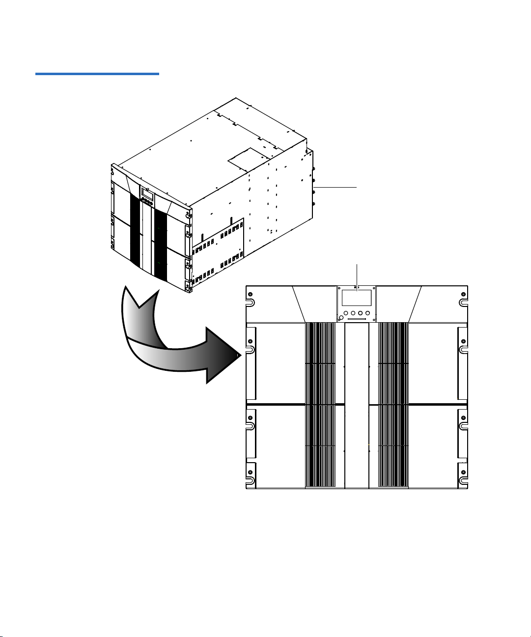
Figure 8 PX506 Front Panel
PX506
Operator control panel (OCP)
Chapter 1 Library Description
Library Features
Quantum PX500 Series User’s Guide 19
Page 43

Figure 9 PX510 Front Panel
PX510
Operator control panel (OCP)
Chapter 1 Library Description
Library Features
Quantum PX500 Series User’s Guide 20
Page 44

Table 6 Front Panel Features
Feature Description
Chapter 1 Library Description
Library Features
Operator
control panel
(OCP)
Magazine
access doors
The operator control panel consists of the following elements:
• OCP display The OCP displays library status information and allows
you to access the library menus. These menus allow you to
view or change the library settings and run diagnostic
tests.
•Five OCP
buttons
The OCP is discussed in detail in chapter 2
These buttons in combination with the OCP are used to
scroll through screens and select options or commands.
.
The functionality of these buttons changes depending on
the currently displayed OCP screen. The power button is
used to turn the library on and off.
• Light emitting
diode (LED)
indicator
The operator control panel has one LED indicators:
• Steady green - indicates a idle state
• Flashing green - indicates a busy state
• Flashing amber - indicates an attention state
• Steady amber - indicates an error
These doors protect the data cartridge magazines.
Quantum PX500 Series User’s Guide 21
Page 45

Chapter 1 Library Description
Elevator
2 fixed bins
Right cartridge
magazine
Tape drives
Gripper
Left cartridge
magazine
Library Features
Internal Layout 1
Figure 10 PX502 Internal
Layout
Figure 10 illustrates the internal layout of a PX502 library. Figure 11
illustrates the internal layout of a PX506 library.
Quantum PX500 Series User’s Guide 22
Page 46

Elevator
Fixed bins (19 on right side)
Cartridge Magazines
(2 on left side)
Tape drives
Gripper
Tap e
drives
Fixed bins
(9 on left side)
Cartridge Magazines
(2 on right side)
Chapter 1 Library Description
Library Features
Figure 11 PX506 Internal
Layout
Quantum PX500 Series User’s Guide 23
Page 47

Figure 12 PX510 Internal
Elevator
Gripper
Tape
drives
Fixed bins
(21 on right side)
Cartridge Magazines
(5 on right side)
(21 on right side)
Layout (Right-View)
Chapter 1 Library Description
Library Features
Quantum PX500 Series User’s Guide 24
Page 48

Figure 13 PX510 Internal
Tap e
drives
Cartridge Magazines
(5 on left side)
(21 on right side)
Layout (Right-View)
Chapter 1 Library Description
Library Features
Quantum PX500 Series User’s Guide 25
Page 49

Chapter 1 Library Description
Library Features
Each cartridge magazine holds 15 SDLT cartridges or 18 LTO cartridges.
The bins in the left magazines are numbered from 1 through 15 (18 in
LTO libraries) from front to back. The bins in the right magazines are
numbered from 1 through 15 (18 in LTO libraries) from back to front.
The PX502 has two fixed slots behind the right magazine. The PX506 has
twenty-eight fixed cartridge slots, nine above each left and right
magazine and ten in a column at the back of the library. PX510 has twenty
one fixed slots in a column at the back of the library. Fixed slots are used
for data cartridges, or for cleaning cartridges, which are moved to a tape
drive when the drive requires cleaning.
A bar code reader is attached to the library’s robotic hand. This bar code
reader automatically identifies the cartridges in the library, if the
cartridges are fitted with acceptable bar code labels.
Back Panel 1
The library back panel provides access to the following items:
• System Controller Board (SCB)
• Power Supplies
• CPCI Card Cage
• Tape Drives
• Cooling Fans
System Controller Board (SCB) 1
The system controller board (SCB) contains the library firmware and
processor. Two Ethernet ports are available for remote management of
the library. The SCB (when not in surrogate mode) also provides a
connection to a host system. There are three types of SCBs:
• SCSI SCB - provides two SCSI ports for a host connection and a
tape drive connection
• Fibre Channel SCB - provides a single Fibre Channel port for a
host connection
• Surrogate SCB (PX502 Only) - provides the ability to allow the
SCSI bus on tape drive one to also act as the media changer
Quantum PX500 Series User’s Guide 26
Page 50

Chapter 1 Library Description
:DUQLQJ +D]DUGRXV 0RYLQJ 3DUWV
.HHS )LQJHUV DQG 2WKHU %RG\
3DUWV $ZD\ :KHQ 5HPRYLQJ
DQ
G ,QVWDOOLQJ 7DSH
'ULYHV
:DUQLQJ +D]DUGRXV 0RYLQJ 3DUWV
.HHS
)LQJHUV DQG 2WKHU %RG\
3DU
WV $ZD\ :KHQ 5HPRYLQJ
DQG ,QVWDOOLQJ 7DSH
'ULYHV
:DUQXQJ *HIlKUOLFKH EHZHJOLFKH
7HLOH +DOWHQ 6LH GLH
)LQJHU XQG DQGHUH
.|USHUWHLOH ZHJ ZHQQ
6LH %DQGODXIZHUNH
HQWIHUQHQ XQG
DQEULQJHQ
:DUQXQJ *HIlKUOLFKH EHZHJOLFKH
7HLOH +DOWHQ 6LH GLH
)LQJHU
XQG DQGHUH
.|USHUWHLOH
ZHJ ZHQQ
6LH %DQGODXIZHUNH
HQ
WIHUQHQ
XQG
DQEULQJHQ
Library Features
Power Supplies 1
The power supplies provide redundant power to the library. The PX502
can contain up to two power supplies (one power supply in the base
unit). The PX506 can contain up to four power supplies (two power
supplies in the base unit). The PX510 contains six power supplies.
CPCI Card Cage 1
The CPCI (compact PCI) card cage provides space for option cards such
as the FC1202 Fibre Channel bridge and TC2201 iSCSI bridge. The PX502
can contain one option card. The PX506 can contain up to four option
cards. The PX510 can contain up to six option cards.
Tape Drives 1
The PX502 can contain up to two tape drives. The PX506 can contain up to
six tape drives. The PX510 can contain up to ten tape drives.
Quantum PX500 Series User’s Guide 27
Cooling Fans 1
Both the PX506 and PX510 contain cooling fans in the library chassis in
addition to the cooling fans located in each tape drive and power supply.
The PX506 and PX510 both contain two cooling fans in the library chassis.
Figure 14 illustrates the back panel of the PX502 library. Figure 15
illustrates the back panel of the PX506 library. Figure 16 illustrates the
back panel of the PX510 library.
Page 51

Figure 14 PX502 Back Panel
Tap e
drives
CPCI card cage
System controller board
Power connectorsPower supplies
Chapter 1 Library Description
Library Features
Quantum PX500 Series User’s Guide 28
Page 52

Figure 15 PX506 Back Panel
Tap e
drives
CPCI card cage
System controller
board
Power
connectors
Power supplies x 4
Cooling fanCooling fan
Tape drives x 6
Chapter 1 Library Description
Library Features
Quantum PX500 Series User’s Guide 29
Page 53

Figure 16 PX510 Back Pane
CPCI card cage
System controller
board
Power
connectors
Power supplies x 6
Cooling fans
Tape drives
x 10
Power
connectors
Chapter 1 Library Description
Library Features
Quantum PX500 Series User’s Guide 30
Page 54

DLTSage™ Tape Security
The PX500 Series tape libraries with DLT-S4 tape drives are capable of
utilizing DLTSage Tape security. DLTSage Tape Security is a unique
solution designed to prevent unauthorized access to tape cartridges
which is particularly valuable when protecting tapes that are transported
offsite. DLTSage Tape Security is a firmware feature designed into the
DLT-S4 tape drive which uses an electronic key to prevent or allow
reading and writing of data on to a tape cartridge. This key is managed
through the remote management pages of the PX500 Series tape library
(see
chapter 3, “Quantum PX500 Series Remote Management,”). DLTSage
Tape Security is available at no additional cost as an integrated feature in
of the DLT-S4 tape drive and PX500 Series tape library (firmware version
20 or later).
Chapter 1 Library Description
DLTSage™ Tape Security
Mixed Media Support
The PX500 Series libraries are capable of supporting mixed media in the
same library (SDLT and LTO media) tape drives and media in the same
library frame. You must have at least one magazine type (SDLT or LTO)
for each tape drive type (SDLT or LTO).
Library Scalability (Stacked Configurations)
The PX502, PX506, and PX510 library modules can be used as stand-alone
libraries, or combined with other PX500 Series library modules in a
standard 19-inch rack to form a larger library system (called a multiple
Quantum PX500 Series User’s Guide 31
Page 55

Figure 17 Multiple Library
Bottom robot lifting pass
through into top library
Pass through in top
library
Top gripper
Stack (Cross Section
library stack). The multiple library or stacked configuration appears as a
single large capacity library to the host (see
Note: It is recommended to place the Master library in the middle of
the library stack for improved performance.
Chapter 1 Library Description
Library Scalability (Stacked Configurations)
figure 17).
Table 7 lists the capacities of all the sizes of multiple library stacks created
using PX502 library modules. Table 8 lists the capacities of all multiple
library stacks created using PX506 library modules. Table 9 lists the
capacities of all multiple library stacks created using PX510 library
modules.You can obtain different capacities by combining PX502, PX506,
and PX510 library modules in a multiple library stack.
Quantum PX500 Series User’s Guide 32
Page 56

Table 7 Capacity, PX502
Multiple Library Stack (42U
High Rack)
# of
Cartridges
Chapter 1 Library Description
Library Scalability (Stacked Configurations)
*
Capacity (in TB)
SDLT 320 SDLT 600 DLT-S4 HP LTO Gen 2 HP LTO Gen 3
*
†
# of PX502 Library Modules
Max. # of Tape Drives
SDLT
LTO
Native
Compressed
Native
†
Compressed
Native
†
Compressed
Native
†
Compressed
†
Native
1 2 32 40 5.1 10.2 9.6 19.2 26.4 52.8 7.6 15.2 15.2 30.4
2 4 64 80 10.2 20.4 19.2 38.4 52.8 105.6 14.4 28.8 28.8 57.6
3 6 96 120 15.3 30.6 28.8 57.6 79.2 158.4 22.0 44.0 44.0 88.0
4 8 128 160 20.4 40.8 38.4 76.8 105.6 211.2 29.6 59.2 59.2 118.4
5 10 160 200 25.5 51 48.0 96.0 132 264 37.2 74.4 74.4 148.8
6 12 192 240 30.6 61.2 57.6 115.2 158.4 316.8 44.8 89.6 89.6 179.2
7 14 224 280 35.7 71.4 67.2 134.4 184.8 369.6 52.4 104.8 104.8 209.6
8 16 256 320 40.8 81.6 76.8 153.6 211.2 422.4 60.0 120.0 120.0 240.0
9 18 288 360 45.9 91.8 86.4 172.8 237.6 475.2 67.6 135.2 135.2 270.4
10 20 320 400 51 102 96 288 264 528 75.2 150.4 150.4 300.8
*.The values in the # of Cartridges and Capacity columns assume that all the magazines and fixed cartridge slots are fully populated
with data cartridges.
†
Compressed values assume 2:1 compression ratios.
Compressed
Quantum PX500 Series User’s Guide 33
Page 57

Table 8 Capacity, PX506
Multiple Library Stack (42U
High Rack)
# of
Cartridges
*
Chapter 1 Library Description
Library Scalability (Stacked Configurations)
Capacity (in TB)
SD LT 320 SD LT 600 DLT-S4 H P LTO Gen 2 HP LTO Ge n 3
*
†
# ofPX506 Library Modules
Max. # of Tape Drives
SDLT
LTO
Native
Compressed
Native
†
Compressed
Native
†
Compressed
Native
†
Compressed
Native
1 6 88 100 14.8 28.7 26.4 52.8 70.4 140.8 20.0 40.0 40.0 80.0
2 12 176 200 29.6 57.4 52.8 105.6 140.8 281.6 40.0 80.0 80.0 160.0
3 18 264 300 44.4 86.1 79.2 154.8 211.2 422.4 60.0 120.0 120.0 240.0
4 24 352 400 59.2 114.8 105.6 207.6 281.6 563.2 80.0 160.0 160.0 320.0
*.The values in the # of Cartridges and Capacity columns assume that all the magazines and fixed cartridge
slots are fully populated with data cartridges.
†
Compressed values assume 2:1 compression ratios.
Table 9 Capacity, PX510
Multiple Library Stack (42U
High Rack)
# of
Cartridges
*
Capacity (in TB)
SD LT 320 SD LT 600 DLT-S 4 HP LTO Ge n 2 HP LTO G en 3
*
†
Compressed
# ofP X510 Library Modules
†
Max. # of Tape Drives
SDLT
LTO
Native
Compressed
Native
†
Compressed
Native
†
Compressed
Native
†
Compressed
Native
†
Compressed
1 10 170 200 51 102 136.8 273.6 40 80 80 160
2 20 340 400 102 204 273.6 555.2 80 160 160 320
Quantum PX500 Series User’s Guide 34
Page 58

Chapter 1 Library Description
Getting Started
*.The values in the # of Cartridges and Capacity columns assume that all the magazines and fixed cartridge
slots are fully populated with data cartridges.
†
Compressed values assume 2:1 compression ratios.
Getting Started
This chapter describes the procedures necessary to get your Quantum
PX500 Series up and running. Have the following equipment and
accessories available before installing the library:
• SCSI cables to support 1 host bus adapter (HBA) per two tape drives
• HBAs in the host
•2 tape drives per SCSI bus)
Note: SDLT 600, DLT-S4, and LTO-3 tape drives require a
dedicated SCSI bus for each tape drive (1 tape drive per
SCSI bus).
• Power source (see appendix A on page 189 for power requirements)
• Tape cartridges (LTO and/or SDLT)
After the Quantum PX500 Series is in it’s final location, the following
steps are required to complete the installation:
• Installing the Quantum PX500 Series
• Cabling the Quantum PX500 Series
• Loading Tape Cartridges
• Initial Configuration
Installing the Quantum
PX500 Series 1
The PX500 Series library modules fit into a standard 19-inch wide rack.
Refer to
figure 10 and figure 11 for rack space requirements. Complete
mounting information is provided in the Quantum PX502 Series Quick
Start (PN 81-81292-01 A01) and the Quantum PX506 and PX510 Unpacking
and Installation Instructions (PN 81-81338-01_A01).
Quantum PX500 Series User’s Guide 35
Page 59

Table 10 Rack Space
8 LQ PP
LQ PP
LQ PP
LQ PP
LQ PP
LQ PP
7RSRIUDFN
LQ P P
LQ PP
+ROHSDWWHUQ
1 PX502 library
module (4U)
1 PX506 library
module (10U)
Requirements (PX502 and
PX506)
Chapter 1 Library Description
Getting Started
Quantum PX500 Series User’s Guide 36
Page 60

Table 11 Rack Space
8 LQ PP
LQ PP
LQ PP
LQPP
LQ PP
LQ PP
7RSRIUDFN
LQ P P
LQPP
+ROHSDWWHUQ
1 PX510 library
module (18U)
Requirements (PX510)
Chapter 1 Library Description
Getting Started
Quantum PX500 Series User’s Guide 37
Page 61

Chapter 1 Library Description
Ethernet port
System controller board
PX502 shown
Getting Started
Warning: If the rack is empty at the time of installation, do NOT
install the PX-Series modules too high in the rack. The
combined weight of the components may cause the rack
to become “top heavy” and unstable if installed in the top
of an empty rack. If installing a multiple library stack,
begin installing the bottom library module first.
Cabling the Quantum PX500 Series 1
Figure 18 Connecting the
Library to the Local Area
Network
After the Quantum PX500 Series is in its final location, the tape drives
and system controller board must be connected to the backup host
system(s).
To cable the Quantum PX500 Series:
1 The PX500 Series tape drives and system controller board are
accessed from the back of the library (refer to
“Connecting to Host
Workstations” on page 51).
2 Connect Ethernet port located on the back of the library on the
system controller board to the local area network (see
figure 18).
Loading Tape Cartridges 1
Before operating the library, load the appropriate tape cartridges (LTO or
SDLT) into the library starting with the left-hand panels (see
“Library
Models” on page 2 for slot locations).
Quantum PX500 Series User’s Guide 38
Page 62

Chapter 1 Library Description
Getting Started
Initial Configuration 1
The Quantum PX500 Series must be initially configured with an IP
address before the remote management software is available. Refer to
“Using the OCP” on page 60 for information on configuring your PX500
Series network information and preparing for operation.
Quantum PX500 Series User’s Guide 39
Page 63

This chapter describes the following basic library operating procedures:
• Installing Tape Cartridges
• Preparing the Library for Operation
• Turning the Library On and Off
• Using the OCP
Installing Tape Cartridges
Chapter 2
2Basic Library Operations
To install tape cartridges:
1 Label each cartridge (see “SDLT Cartridges” on page 43 and “LTO
Cartridges” on page 45 for information on cartridge labels).
2 Set the write-protect switch to either write protect or write enable (see
“SDLT Cartridges” on page 43 and “LTO Cartridges” on page 45 for
information on write-protect switches).
Quantum PX500 Series User’s Guide 40
Page 64

Chapter 2 Basic Library Operations
Installing Tape Cartridges
3 Place cartridges (right side up) in the fixed slots and magazines:
a Open the library doors (see “Library Operations” on page 68 to
open the library doors).
Note: In a PX506 and PX510 library, the bottom doors must be
open to open the top doors.
b Remove the magazines (see “Library Operations” on page 68 to
release the magazines).
Note: You have approximately 10 seconds to open the doors and
remove the magazines. If you did not complete the
operation, repeat the steps.
Note: In a PX506 and PX510 library, only the bottom magazines
must be released from the OCP. All other magazines can
be removed without being released.
c Load the tape cartridges in the magazines and fixed bins. It is
recommended to start loading tape cartridges in magazine 1, bin
0000 (see
“Library Models” on page 2 for magazine and bin
locations).
Warning: Do NOT reach into the library to load tape cartridges
into the fixed bins. Use the
Operations tab from the remote management pages
(see
chapter 3 on page 85) to move tape cartridges
Move page located on the
from the magazines into the fixed bins.
d Replace the magazines in the library.
e Close the library doors.
Caution: Placing the cartridges in the bins upside down can
cause damage to the library (see
figure 20 for SDLT
cartridges and figure 21 for LTO cartridges).
Quantum PX500 Series User’s Guide 41
Page 65

Chapter 2 Basic Library Operations
Unplug all AC cords to remove power from equipment.
Installing Tape Cartridges
Caution: Handle tape cartridges with care. Do not drop or bang
them, or place them near sources of electromagnetic
interference. Rough handling can displace the tape
leader, making the cartridge unusable and potentially
hazardous to the tape drives. Loss of data could result
from damaged tape cartridges inserted in tape drives.
Taking ESD Precautions2
Components within the PX500 Series contain static-sensitive parts. To
prevent damage to these parts while performing installation,
maintenance, or replacement procedures, observe the following
precautions:
• Keep the cabinet turned off during all installation, maintenance, and
replacement procedures.
• Keep the cabinet power cord connected to a grounded power outlet
except when working with AC electrical components.
Warning: Avoid contact with the power supplies, EMI filter, and all
other AC electrical components while the cabinet is
connected to a power outlet.
• Use an antistatic wrist strap when touching internal cabinet
components. To use the wrist strap properly, place the band around
your wrist and attach the clip to the cabinet frame. Keep the strap on
until you are ready to close the cabinet doors.
• Keep static-sensitive parts in their shipping containers until ready for
installation.
• Do not place static-sensitive parts on any metal surface. If you need to
Quantum PX500 Series User’s Guide 42
put down a static-sensitive part, place it inside its protective shipping
bag or on a grounded antistatic mat.
Page 66

Chapter 2 Basic Library Operations
Installing Tape Cartridges
• Avoid direct contact with static-sensitive parts. Avoid touching
connectors and discrete components.
• Close cabinet door and access panel when not working on the
cabinet.
• Be very careful when installing the cabinet or handling components
in dry climates or environments where cold weather heating is used.
Environments such as these with lower relative humidity have
greater potential to produce static electricity.
Note: In environments with high potential for static electricity,
take additional precautions such as the use of an antistatic
smock or a grounded antistatic mat.
SDLT Cartridges 2
The following section shows you how to label SDLT tape cartridges, as
well as setting the write-protect switch and proper orientation.
Labeling 2
Attaching a barcode label to each tape cartridge enables the cabinet to
identify the cartridge quickly, thereby speeding up inventory time.
The SDLT cartridge label has eight characters (e.g. AAANNNS#). The
first six characters are called the volume identifier which is made up of
three alpha characters and three numeric characters. These characters
allow each cartridge to have a unique identifier. The last two characters
are called the media identifier and indicate the following media types:
• S1 = SDLT 220
• S2 = SDLT 320
• S3 = SDLT 600
•S4 = DLT-S4
Note: You cannot choose the sequence of labels inside the bar code
label packs. No two packs are ever the same to avoid issues
with duplicate bar code IDs.
Place the label in the slide-in slot on the front of the cartridge (see
figure 19).
Quantum PX500 Series User’s Guide 43
Page 67

Figure 19 Inserting a Barcode
Slide-in slot
Label (SDLT)
Chapter 2 Basic Library Operations
Installing Tape Cartridges
Note: Only use barcode labels that have been designed for
cartridges. Do not adhere labels to a cartridge anywhere
except the slide-in slot.
Setting the Write-Protect Switch 2
Each tape cartridge has a write-protect switch similar to that shown in
figure 20. This switch determines whether new data can be written to the
cartridge (write-enabled) or whether data on the cartridge is protected
from being erased or overwritten (write-protected). Set the write-protect
switch to enabled when inserting new cartridges into the library. Set the
write-protect switch to protected archiving tape cartridges.
Proper Insertion Orientation 2
Refer to figure 20 for proper label placement, write protection settings
and insertion orientation.
Quantum PX500 Series User’s Guide 44
Page 68

Figure 20 SDLT Cartridges
Barcode label
Insertion arrow
I
n
s
e
r
t
t
h
i
s
e
n
d
i
n
t
o
t
h
e
s
l
o
t
Orange
window
Write
protect
Write
enable
(SDLT cartridge shown)
Slide right (default)
Slide left
Chapter 2 Basic Library Operations
Installing Tape Cartridges
LTO Cartridges 2
Quantum PX500 Series User’s Guide 45
LTO tape cartridges are different in size to the SDLT cartridges as well as
in the barcode labeling and write-protect switch setting (see
The LTO cartridge label has eight characters (e.g. AAANNNL#). The first
six characters are called the volume identifier which is made up of three
alpha characters and three numeric characters. These characters allow
each cartridge to have a unique identifier. The last two characters are
figure 21).
called the media identifier and indicate the following media types:
• L1 = LTO generation 1 (LTO)
• L2 = LTO generation 2 (LTO-2)
• L3 = LTO generation 3 (LTO-3)
Note: You cannot choose the sequence of labels inside the bar code
label packs. No two packs are ever the same to avoid issues
with duplicate bar code IDs.
Page 69

Figure 21 LTO Cartridges
ABC123L1
Barcode label
Insertion arrow
In
se
r
t
t
h
is
en
d
in
t
o
t
h
e s
lo
t
Write
protect
Write
enable
Slide left (default)
Slide right
Chapter 2 Basic Library Operations
Installing Tape Cartridges
Adhesive-backed barcode labels are used on LTO tape cartridges. Refer
to
figure 21 for proper label placement, write protection settings and
insertion orientation.
Cleaning Cartridges 2
Quantum PX500 Series User’s Guide 46
Caution: LTO tape drive media cannot be degaussed due to the fact
that it uses "magnetic servos." Do not attempt to degauss
LTO tape drive media. If this media is degaussed, it will
no longer work.
Cleaning cartridges are used when a tape drive within the library
requires cleaning. When Autoclean is enabled (either through the OCP or
remote management screens), the library will automatically clean the
tape drive when needed. A fixed bin (see
“Library Models” on page 2 for
bin locations) is generally used to store a cleaning cartridge, however, the
cartridge can be placed anywhere in the library. When the library
completes the inventory, the system stores the cleaning cartridge location
so it will be available when a tape drive requires cleaning.
Both SDLT and LTO cleaning cartridge labels begin with CLN (see
figure 22 for SDLT and figure 23 for LTO).
Page 70

Figure 22 SDLT Cleaning
Cartridges
Chapter 2 Basic Library Operations
Installing Tape Cartridges
Figure 23 LTO Cleaning
Cartridges
Quantum PX500 Series User’s Guide 47
Page 71

Preparing the Library for Operation
Right door
Left door
To prepare the cabinet for operation:
• Close the Cabinet Doors and Access Panels
• Connecting to Host Workstations
Chapter 2 Basic Library Operations
Preparing the Library for Operation
Close the Cabinet Doors
and Access Panels 2
Figure 24 Closing the PX502
Front Doors
The PX500 Series libraries have doors covering the tape cartridge
magazines.
1 Close the front doors until they latch:
• PX502 - see figure 24
• PX506 - see figure 25
• PX510 - see figure 26
Quantum PX500 Series User’s Guide 48
Page 72

Figure 25 Closing the PX506
Right doors
Left doors
Front Doors
Chapter 2 Basic Library Operations
Preparing the Library for Operation
Quantum PX500 Series User’s Guide 49
Page 73

Figure 26 Closing the PX510
Right doors
Left doors
Front Doors
Chapter 2 Basic Library Operations
Preparing the Library for Operation
Quantum PX500 Series User’s Guide 50
Page 74

Chapter 2 Basic Library Operations
Preparing the Library for Operation
Connecting to Host Workstations 2
Connect the SCSI or Fibre Channel cables as shown in the following
figures:
PX502 Cabling Configurations 2
• PX502 Cabling Configuration (SCSI)
• PX502 Cabling Configuration (Surrogate)
• PX502 Cabling Configuration (Native Fibre Channel)
PX506 Cabling Configurations 2
• PX506 Cabling Configuration (SCSI)
• PX506 Cabling Configuration (Native Fibre Channel)
PX510 Cabling Configurations 2
• PX510 Cabling Configuration (SCSI)
• PX510 Cabling Configuration (Native Fibre Channel)
Note: Quantum ships sufficient SCSI cables and terminators with the
libraries to set up two-drives per SCSI bus.
Stacked Configuration 2
• PX502 Stacked Cabling Configuration
Quantum PX500 Series User’s Guide 51
Page 75

Figure 27 PX502 Cabling
SCSI jumper cables SCSI terminator
Host computer
Tape
drive 1
Tape
drive 2
Configuration (SCSI)
Chapter 2 Basic Library Operations
Preparing the Library for Operation
Quantum PX500 Series User’s Guide 52
Page 76

Figure 28 PX502 Cabling
SCSI jumper cables
SCSI terminator
Host computer
Tape
drive 1
Ta pe
drive 2
SCSI surrogate cabling shown. Native Fiber
Channel systems also have the host connected to
tape drive one.
Fibre Channel host/SAN
Tape
drive 1
Tape
drive 2
Fibre Channel ports
LTO-2, -3 native Fibre
Channel drives shown. SDLT
600 and DLT-S4 native Fibre
Channel drives have only one
FC port
Configuration (Surrogate)
Chapter 2 Basic Library Operations
Preparing the Library for Operation
Figure 29 PX502 Cabling
Configuration (Native Fibre
Channel)
Quantum PX500 Series User’s Guide 53
Page 77

Figure 30 PX506 Cabling
Host computer
Host computer
Host computer
SCSI
jumper
SCSI jumper
SCSI
terminators
SCSI jumper
Tape
drive 1
Tape
drive 3
Tape
drive 5
Tape
drive 2
Tape
drive 4
Tape
drive 6
Configuration (SCSI)
Chapter 2 Basic Library Operations
Preparing the Library for Operation
Quantum PX500 Series User’s Guide 54
Page 78

Figure 31 PX506 Cabling
Tape
drive 1
Tape
drive 3
Tape
drive 5
Tape
drive 2
Tape
drive 4
Tape
drive 6
Fibre Channel
host/SAN
Fibre Channel
ports
Fibre Channel
ports
Fibre Channel
ports
LTO-2, -3 native
Fibre Channel
drives shown.
SDLT 600 and DLTS4 native Fibre
Channel drives
have only one FC
port
Configuration (Native Fibre
Channel)
Chapter 2 Basic Library Operations
Preparing the Library for Operation
Quantum PX500 Series User’s Guide 55
Page 79

Figure 32 PX510 Cabling
Host computer
Host computer
Host computer
SCSI jumper
SCSI
terminators
SCSI
jumper
Host computer
Host computer
SCSI
terminators
SCSI
jumper
SCSI
jumper
Tape
drive 1
Tape
drive 3
Tape
drive 5
Tape
drive 2
Tape
drive 4
Tape
drive 6
Tape
drive 7
Tape
drive 8
Tape
drive 9
Tape
drive 10
Configuration (SCSI)
Chapter 2 Basic Library Operations
Preparing the Library for Operation
Quantum PX500 Series User’s Guide 56
Page 80

Figure 33 PX510 Cabling
Tape
drive 1
Tape
drive 3
Tape
drive 5
Tape
drive 2
Tape
drive 4
Tape
drive 6
Tape
drive 7
Tape
drive 8
Tape
drive 9
Tape
drive 10
Fibre Channel
host/SAN
Fibre Channel
ports
Fibre Channel
ports
Fibre Channel
ports
Fibre Channel
ports
Fibre Channel
ports
LTO-2, -3 native
Fibre Channel
drives shown. SDLT
600 and DLT-S4
native Fibre
Channel drives
have only one FC
port
Configuration (Native Fibre
Channel)
Chapter 2 Basic Library Operations
Preparing the Library for Operation
Quantum PX500 Series User’s Guide 57
Page 81

Figure 34 PX502 Stacked
PX502 (master library)
PX502 (slave library)
PX502 (slave library)
Host computer
Tape
drive 1
Tape
drive 2
Tape
drive 2
Tape
drive 1
Tape
drive 1
Tape
drive 2
Host computer
Host computer
Ethernet
The library host and Ethernet
network are connected only to
the Master library.
Cabling Configuration
Chapter 2 Basic Library Operations
Preparing the Library for Operation
Quantum PX500 Series User’s Guide 58
Page 82

Turning the Library On and Off
Power button
OCP
This section explains:
• Turning On the Library
• Turning Off the Library
• Placing the Library On-line or Off-line
Chapter 2 Basic Library Operations
Turning the Library On and Off
Turning On the Library 2
Figure 35 Turning On the
Library
To turn on the library:
1 Verify that:
• Power cables are firmly in place
• All doors are closed
2 Push the power button located in the lower left-hand corner of the
OCP (see
figure 35).
During the power up sequence, the library performs an inventory.
The power up sequence can take several minutes.
Quantum PX500 Series User’s Guide 59
Page 83

Chapter 2 Basic Library Operations
Using the OCP
Turning Off the Library 2
Placing the Library Online or Off-line 2
Using the OCP
To turn off the library:
1 Push the power button located on the front of the library and hold for
approximately 1 second (see
The library begins the shutdown sequence. The shutdown sequence
can take up to two minutes to complete.
With the library turned on, press the button corresponding to Ops on the
OCP to access the
Library on/offline to turn the library off-line. Select Yes or No to confirm
the library state change. For more information on the
see
“Library Operations” on page 68.
The operator control panel (OCP) is located on the front of the library.
The menus on the OCP allow you to obtain information about the library,
execute library commands, and test library functions. Before using the
OCP to perform library functions, familiarize yourself with the:
Operations screen. Select Library Operations and then
figure 35).
Operations screen,
• Home Screen
• OCP Buttons
Home Screen 2
Quantum PX500 Series User’s Guide 60
The first screen the OCP displays after library initialization is the main
screen. This screen displays library status and provides information on
the number of tape drives, slots, and serial number (see
figure 2).
Page 84

OCP Home Screen 2
Power
button
Library
status
Button
labels
Push
buttons
Press this
button
To s e l ec t t hi s
function
Chapter 2 Basic Library Operations
OCP Components
OCP Buttons 2
OCP Components
Quantum PX500 Series User’s Guide 61
At the bottom of each OCP screen are four button labels. These labels
indicate the functions of the four push buttons below the OCP. To select a
function, press the push button directly below the button label on the
OCP screen. The OCP also contains a power button for turning the library
on and off.
The OCP allows the user to perform various functions on the Quantum
PX500 Series library.
Table Figure 36 provides a list of the OCP
functionality available from the Home screen (see figure 2).
Page 85

Figure 36 OCP Component
,QIRPHQX
2YHUYLHZ
)LUPZDUH,QIRUPDWLRQ
)LUPZDUHUHYLVLRQ
'DWHDQGWLPHRIUHY
1HWZRUN,QIRUPDWLRQ
,3DGGUHVV
1HWZRUN0DVN
*DWHZD\
6\VWHP
'RRUV
3RZHU6XSSO\
5RERWLFV
2&3
'ULYHV
+DUG(YHQWV
6RIW(YHQWV
&RGH8SGDWH(YHQWV
%RRW(YHQWV
+DUGZDUH,QIRUPDWLRQ
(YHQW/RJV
/LEUDU\RQRIIOLQH
5HOHDVH0DJD]LQHV
3DUNIRU6KLSSLQJ
/LEUDU\2SHUDWLRQV
6HDUFKIRUODEHO
6HDUFKIRUPHGLD,'
)LQG7DSH
(ODSV7P
3F\FOHV
6ORW*HW
6ORW3XW
6OW5HW*
6OW5HW3
'UY*HW
'UY3XW
'UY5HW*
'UY5HW3
6WDWLVWLFV
+HDOWKWHVW
6HOIWHVW
&DOLEUDWLRQVWDWV
5DQGRPORDGXQORDG
5DQGRPVORWVRQO\
5DQGRPGULYHIRFXV
6HTXHQWLDOELQV
6HTXHQWLDOGULYHV
6\VWHPOHYHOWHVWV
+RVWEXV
6WDFNUROH
/HIWORDGSRUW
5LJKWORDGSRUW
'ULYH)83IURPWDSH
)XOO,QYHQWRU\
&DELQHW
%DUFRGHVZDS
(PXODWLRQ
$XWRFOHDQ
&RQILJXUH6ORWV
3DUWLWLRQV
6HWDGPLQ3,1
6HWRSHUDWRU3,1
6HFXULW\
'+&3
,3DGGUHVV
6XEQHWPDVN
'HIDXOWJDWHZD\
(WKHUQHW
1HWZRUN
7LPH]RQH
6WDQGDUGWLPH
'D\OLJKWVDYLQJVWLPH
'DWHDQG7LPH
'UY/G5
'UY8QO5
;<PRYH
=PRYH
3PRYH
5PRYH
;<UHWU\
=UHWU\
3UHWU\
5UHWU\
2SVPHQX 6HWXSPHQX 'LDJVPHQX
/HIWPDJV
5LJKWPDJV
0RYH7DSH
'ULYHV
+DQG7RS3DVVWKUX
'ULYH2SHUDWLRQV
6FDQ,QYHQWRU\
'ULYHV
3ZURQ
3ZURII
UHVHW
'ULYH7\SH
6HULDO1XPEHU
)LUPZDUH5HYLVLRQ
;<WHVW
=WHVW
5RWDWLRQVWDWV
7UDQVODWLRQWHVW
&DPHUDWHVW
7HPSHUDWXUHWHVW
+RPHSRVLWLRQ
&RPSRQHQWWHVWV
;<=WHVW
+DQGDVVHPEO\WHVW
6XEV\VWHPWHVWV
Tree
Chapter 2 Basic Library Operations
OCP Components
Quantum PX500 Series User’s Guide 62
Page 86

Chapter 2 Basic Library Operations
Enter
OCP Components
The following sections provide information on each function available
from the Quantum PX500 Series OCP:
• Info Screen
• Operations Screen
• Setup Screen
• Diags Screen
Info Screen 2
Figure 37 Info Screen
The Info screen provides access to library information such as hardware
status, event logs, and statistics.
To access the Info screen, press Info from the Home screen. The OCP
displays the
Info screen (see figure 37):
The Info screen provides the following choices:
• Overview Information
• Hardware Information
• Event Logs
• Statistics Information
Overview Information 2
To view overview information:
Quantum PX500 Series User’s Guide 63
Page 87

Figure 38 Overview Screen
Chapter 2 Basic Library Operations
OCP Components
1 From the Info screen, use the up and down arrows to highlight
Overview and press Enter.
The Overview screen displays (see figure 38):
The Overview screen displays the following information about the
library:
•Firmware revision
• Time and date the firmware was built
2 Press Back or Next to review the network information such as the
current IP address, network mask, and gateway information.
3 When you are finished viewing overview information, press Exit to
return to the
Info screen.
Quantum PX500 Series User’s Guide 64
Page 88
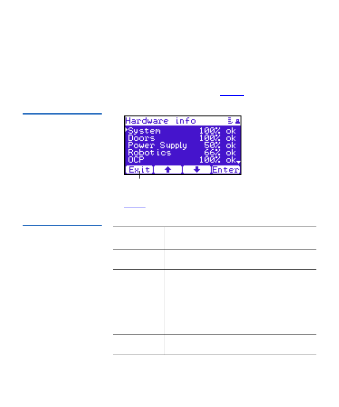
Figure 39 Hardware Screen
Exit
Chapter 2 Basic Library Operations
OCP Components
Hardware Information 2
To view hardware information:
1 From the Info screen, use the up and down arrows to highlight
Hardware and press Enter.
The Hardware screen displays (see figure 39):
The Hardware screen displays the following information (see
table 40):
Figure 40 Hardware
Information
Hardware
Information Description
System System information displays the overall sensor
details for the library.
Doors Door information displays the door sensor details.
Power Supply Power supply information displays the power
supply sensor details.
Robotics Robotics information displays the robotic sensor
details.
OCP OCP information displays the OCP sensor details.
Drives Drives information displays the tape drive sensor
details.
Quantum PX500 Series User’s Guide 65
Page 89
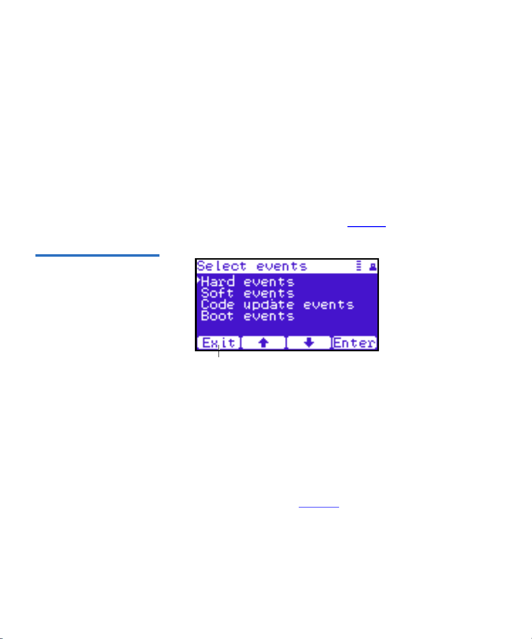
Figure 41 Event Log Screen
Exit
Chapter 2 Basic Library Operations
OCP Components
2 Use the up and down arrows to highlight the information you wish
to display and press
Enter.
3 When you are finished viewing the hardware information, press Exit
to return to the
Info screen.
Event Logs 2
To view the event logs:
1 From the Info screen, use the up and down arrows to highlight Event
Logs
and press Enter.
The Event Log screen displays (see figure 41).
2 Use the up and down arrows to highlight the event type you wish to
view (
Hardware, Software, Code updates, or Boot events).
The OCP displays the event severity list.
3 Use the up and down arrows to highlight the severity type you wish
to view (
All, Critical, Warning, and Informational).
The OCP displays the event or list of events in the specific severity
category. Use the Back and Next buttons to move between events.
4 When you are finished viewing the event logs, press Exit to return to
the
Info screen. Refer to chapter 4 on page 150 for detailed event
information.
Statistics Information 2
To view statistics information:
Quantum PX500 Series User’s Guide 66
Page 90

Figure 42 Statistics Screen
Exit
Chapter 2 Basic Library Operations
OCP Components
1 From the Info screen, use the up and down arrows to highlight
Statistics and press Enter.
The Statistics screen displays (see figure 42):
The Statistics screen displays the following information about the
library:
• ElapsTm – seconds since boot.
• PCycles – total number of power cycles or reboots.
• SlotGet – count of cartridge retrievals from slots.
• SlotPut – count of cartridge deliveries to slots.
• SltRetG – count of retries in retrievals from slots.
• SltRetP – count of retries in deliveries to slots.
• DrvGet – count of cartridge retrievals from drives.
• DrvPut – count of cartridge deliveries to drives.
• DrvRetG – count of retries in retrievals from drives.
• DrvRetP – count of retries in deliveries to drives.
• DrvLdR – count of retries for cartridge loads in drives.
• DrvUnlR – count of retries for cartridge unloads in drives.
• XYmove – count of horizontal moves.
• Zmove – count of vertical moves.
• Pmove – count of extension moves.
• Rmove – count of rotation moves.
Quantum PX500 Series User’s Guide 67
Page 91

Chapter 2 Basic Library Operations
Exit
OCP Components
• XYretry – count of horizontal move retries.
• Zretry – count of vertical move retries.
• Pretry – count of extension move retries.
• Rretry – count of rotation move retries.
When you are finished viewing the statistics information, press Exit
to return to the
Info screen.
Operations Screen 2
Figure 43 Operations Screen
The Operations (Ops) screen allows the user to view the status and issue
commands to the cabinet and tape drives.
To access the Operations screen, press Ops from the Home screen. The
OCP displays the
Operations screen (see figure 43):
The Ops screen provides the following choices:
• Library Operations
• Find Tape
• Move Tape
• Drive Operations
• Scan Inventory
Library Operations 2
To view library operations information:
Quantum PX500 Series User’s Guide 68
Page 92

Figure 44 Library Operations
Screen
Chapter 2 Basic Library Operations
OCP Components
1 From the Ops screen, use the up and down arrows to highlight
Library Operations and press Enter.
The Library Operations screen displays (see figure 44):
The following library operations options are available (see table 12):
Table 12 Library Operations
Options
Library Operations
Options Description
Library on/offline When the cabinet is
for host communication and for backup jobs
to proceed. When the cabinet is
host is no longer able to communicate with
the library. Self tests, diagnostics, and
inventory can only be performed when the
library is
offline.
Use the up and down arrows to highlight
Library on/offline and press Enter to toggle the
Release magazines
library
the command or
Use the up and down arrows to highlight
Release magazines and press Enter to view the
online or offline. Press Yes to confirm
No to cancel.
release magazines screen. Select the magazine
you wish to release and press
to cancel.
Note: If there are no magazines installed or if
the magazines are configured as load ports,
this line will not display.
online, the library is ready
offline, the
Enter. Press Exit
Quantum PX500 Series User’s Guide 69
Page 93

Chapter 2 Basic Library Operations
OCP Components
Library Operations
Options Description
Park for shipping Note: You must remove all tape cartridges
from the library prior to parking the library
robotics for shipment.
Figure 45 Match Label Screen
Use the up and down arrows to highlight
for shipping
and press Enter to move the robot
Park
to a safe position for transport. After the robot
is in it’s final position, the library shuts down.
After the library is shut down, you must
complete the repacking procedure before
transporting the library (see appendix D
on
page 229).
2 When you are finished viewing the library operations information,
press
Exit to return to the Ops screen.
Find Tape 2
To view media or tape cartridge information:
1 From the Ops screen, use the up and down arrows to highlight Find
Tape
and press Enter.
The Match Label screen displays (see figure 45):
2 Use the up and down arrows to cycle through the alpha, numeric, or
wildcard (?) characters to enter the tape cartridge label. After each
character, press
Quantum PX500 Series User’s Guide 70
Enter.
Page 94

Figure 46 Move From Screen
Chapter 2 Basic Library Operations
OCP Components
If a match is found, the cartridge type and location displays.
3 If more than one match is found, a list of matching cartridges
displays. Select the tape cartridge from the list and press
Enter.
The tape cartridge type and location displays.
Move Tape 2
To view the move tape screen:
1 From the Ops screen, use the up and down arrows to highlight Move
Tape
and press Enter.
The Move From screen displays (see figure 46):
To move a tape cartridge within the library:
Note: If this is a master library in a multiple library stack, you
cannot move cartridges from one library into another. You
can only move cartridges manually from one library into
another via the remote management pages (see chapter 3
on page 85).
2 Use the up and down arrows to select a magazine, tape drive, or fixed
slot group and press
Enter.
The Move from screen displays a list of storage bins within the
selected magazine, tape drive, fixed slot group, and hand/top
passthru.
3 Use the up and down arrows to select a tape cartridge from an
occupied bin and press
Quantum PX500 Series User’s Guide 71
Enter.
Page 95

Chapter 2 Basic Library Operations
OCP Components
The Move to screen displays a list of magazine, tape drive, or fixed
slot groups.
4 Use the up and down arrows to select a magazine, tape drive, or fixed
slot group to receive the cartridge and press
Enter.
The Move to screen displays a list of storage elements within the
selected magazine, tape drive, or fixed slot group.
5 Use the up and down arrows to select an empty bin to receive the
tape cartridge and press
Enter.
The Move in progress screen displays. When the tape cartridge has
completed the move, a
Success screen displays.
6 When you are finished moving tape cartridges, press Exit to return to
the
Ops screen.
Drive Operations 2
To perform a drive operation:
1 From the Ops screen, use the up and down arrows to highlight Drive
Operations
and press Enter.
The Drive Operations screen displays (see figure 47):
Figure 47 Drive Operations
Screen
1 Use the up and down arrows to select a tape drive and press Enter.
The following drive options are available (see table 13):
Caution: Ensure that the tape drive does not contain a tape
cartridge prior to powering down the tape drive.
Quantum PX500 Series User’s Guide 72
Page 96

Chapter 2 Basic Library Operations
Enter
OCP Components
Table 13 Drive Options
Device Options Description
Drive Pwr on
This option powers on a specific tape drive
within the cabinet.
Pwr off
This option shuts down a specific tape
drive within the cabinet in preparation for
tape drive removal.
Reset
This option re initializes a specific tape
drive within the cabinet.
2 When you are finished viewing tape drive information, press Exit to
return to the
Ops screen.
Scan Inventory 2
To perform an inventory of the library:
1 From the Ops screen, use the up and down arrows to highlight Scan
Inventory
and press Enter.
The Success screen displays. Press Done to complete.
Setup Screen 2
The Setup screen allows the user to view or edit various library settings
such as date and time, network and host bus information.
To access the Setup screen, press Setup from the Home screen. The OCP
displays the
Figure 48 Setup Screen
Quantum PX500 Series User’s Guide 73
Setup screen (see figure 43):
Page 97

Figure 49 Cabinet Setup
Screen
Chapter 2 Basic Library Operations
OCP Components
The Setup screen provides the following choices:
• Cabinet Setup
• Partitions Setup
• Security
• Network
• Date and Time
Cabinet Setup 2
To view the cabinet setup screen:
1 From the Setup screen, use the up and down arrows to highlight
Cabinet Setup and press Enter.
The Cabinet Setup screen displays (see figure 49):
The Cabinet Setup screen displays the following options (see
table 14):
Table 14 Cabinet Setup
Cabinet Setup Description
Host bus
Select the host bus option to view or edit the SCSI
IDs for the changer (library) and tape drives. The
Host bus option also allows you to set the Fibre
Channel settings for any Fibre Channel tape drives
installed. Loop ID, topology, and speed for each tape
drive can be set.
Quantum PX500 Series User’s Guide 74
Page 98

Chapter 2 Basic Library Operations
OCP Components
Cabinet Setup Description
Stack role Select the stack role option to view or set the library
stack role (stand alone, master, or slave).
Left load port
Select the left load port options to enable/disable the
left load port and also to designate one column or the
entire magazine as a load port.
Right load port
Select the right load port options to enable/disable
the right load port and also to designate one column
or the entire magazine as a load port.
Drive FUP
from tape
Select the magazine or fixed that contains the
firmware update cartridge (FUP) and then the
specific tape drive to update. The library must be
offline to update the tape drive firmware.
Full Inventory When full inventory is on, the library will complete a
full inventory of the tape cartridges whenever a door
is opened. When full inventory is off and a load port
is accessed, the library will only inventory the load
port and not the entire library.
2 When you are finished viewing the cabinet setup information, press
Exit to return to the Setup screen.
Partitions Setup 2
To view or edit the partition information:
1 From the Setup screen, use the up and down arrows to highlight
Partitions and press Enter.
The Partitions Setup screen displays (see figure 50):
Quantum PX500 Series User’s Guide 75
Page 99

Figure 50 Library Setup
Screen
Chapter 2 Basic Library Operations
OCP Components
The Partitions Setup screen displays the following options (see
table 15):
Table 15 Library Setup
Partitions Setup Description
Barcode swap Select the barcode swap to change the barcode
swap option (enable/disable). When enabled, the
media type prefix is swapped from the back of
barcode to the beginning.
Emulation
Select the emulation option to change the library
emulation mode. Emulation options are: PX500 or
P2000.
Auto clean
Select the auto clean option to change the library
autoclean mode (enable/disable). When enabled,
the library will automatically load a cleaning
cartridge when a tape drive requests a cleaning.
Configure Slots The configured slots option allows you to
designate the number of slots available and
reported to the host. Use the up and down arrows
to highlight
the number of configured slots and press
Configure Slots and press Enter. Enter
Enter.
The library will reconfigure with the new slot
count.
2 When you are finished viewing/editing the library setup
information, press
Exit to return to the Setup screen.
Quantum PX500 Series User’s Guide 76
Page 100

Figure 51 Security Screen
Chapter 2 Basic Library Operations
OCP Components
Security 2
To view or edit the security information:
1 From the Setup screen, use the up and down arrows to highlight
Security and press Enter.
The Security screen displays (see figure 51):
The Security screen displays the following options (see table 15):
Table 16 Security Setup
Security Setup Description
Set admin PIN
The admin PIN allows access to all areas of the
OCP. Select
Set admin PIN and use the up and down
arrows to cycle through the PIN numbers. Press
Enter to accept each digit and press Enter twice after
the last digit of the PIN. You must verify the PIN
number. The admin PIN can be 0 to 8 characters
long, numbers only.
Set operator
PIN
The operator PIN only allows access to the
Ops menus of the OCP. The operator cannot change
any library settings. Select
Set operator PIN to set
Info or
the operator PIN. use the up and down arrows to
cycle through the PIN numbers. Press
accept each digit and press
Enter twice after the last
Enter to
digit of the PIN. You must verify the PIN number.
The operator PIN can be 0 to 8 characters long,
numbers only.
Quantum PX500 Series User’s Guide 77
 Loading...