

Page 1

Quantum PX500
Series Tape Drive
Installation Instructions
Introduction 3
Tape Drive Numbering................................................................................3
Upgrade Kits.................................................................................................. 6
Required Tools .............................................................................................. 6
Unpacking the Tape Drive 7
Installing the Tape Drives 7
Cabling the Tape Drives 8
PX502 Libraries..............................................................................................9
PX506 Libraries............................................................................................11
PX510 Libraries............................................................................................13
Setting the Tape Drive SCSI ID 15
Setting the SCSI ID Using the OCP .......................................................... 15
Setting the SCSI ID from the Remote Management Pages ................... 16
Completing the Native Fibre Channel Installation 18
Determining the WWNs World Wide Names........................................18
Verifying Library Connectivity.................................................................22
Fibre Channel Connectivity Troubleshooting 24
Fibre Channel Connectivity Troubleshooting ........................................24
SCSI ID Assignment with Native Fibre Channel Tape Drives............. 25
81-81301-04 A01, August 2006 1
Page 2

Quantum PX500 Series Tape Drive Installation Instructions
81-81301-04 A01
August 2006
Made in the USA.
Quantum Corporation provides this publication “as is” without warranty of any kind, either express or implied, including but not limited to
the implied warranties of merchantability or fitness for a particular purpose. Quantum Corporation may revise this publication from time to
time without notice.
COPYRIGHT STATEMENT
© Copyright 2006 by Quantum Corporation. All rights reserved.
Your right to copy this document is limited by copyright law. Making copies or adaptations without prior written authorization of Quantum
Corporation is prohibited by law and constitutes a punishable violation of the law.
TRADEMARK STATEMENT
Capacity on Demand (CoD), Crosslink Mechanism, DLT, DLTSage, DLTtape, Super DLTtape, Performance on Demand, (PoD), PRISM,
PRISM Storage Architecture logo, SiteCare, StackLink, StorageCare, SuperLoader, and ValueLoader are all trademarks of Quantum
Corporation. Quantum, the Quantum logo, and the DLTtape logo are all registered trademarks of Quantum Corporation.
Other trademarks may be mentioned herein which belong to other companies.
2
Page 3

Quantum PX500 Series Tape Drive Installation Instructions
81-81301-04 A01
August 2006
Introduction 0
This document provides instructions for adding a tape drive to an Quantum
PX500 Series tape library. The tape drive upgrade procedure consists of the
following steps:
• Unpacking the Tape Drive
• Installing the Tape Drives
• Cabling the Tape Drives
• Setting the Tape Drive SCSI ID
• Completing the Native Fibre Channel Installation
• Fibre Channel Connectivity Troubleshooting
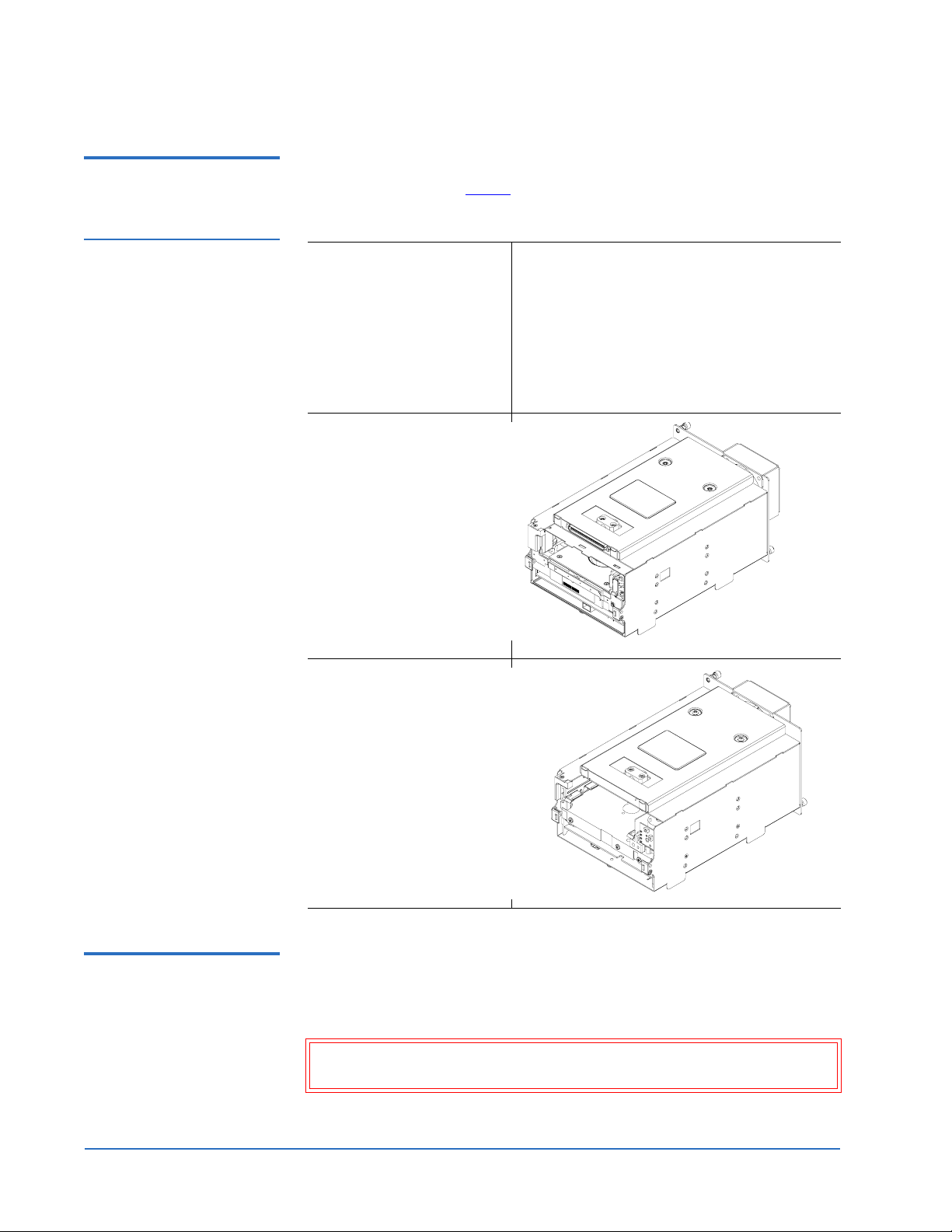
Tape Drive Numbering 0 The Quantum PX500 Series tape library may contain up to 10 tape drives
depending on the library model. Refer to the following figures:
Figure 1 Quantum PX502
Tape Drive Numbering
• Figure 1
• Figure 2
• Figure 3
- PX502 Tape Drive Numbering (up to two tape drives)
- PX506 Tape Drive Numbering (up to six tape drives)
- PX510 Tape Drive Numbering (up to ten tape drives)
Tape drive 2 Tape drive 1
Introduction 3
Page 4

Quantum PX500 Series Tape Drive Installation Instructions
81-81301-04 A01
August 2006
Figure 2 Quantum PX506
Tape Drive Numbering
Tape
drive 2
Tape
drive 1
Tape
drive 4
Tape
drive 6
Tape
drive 3
Tape
drive 5
4 Introduction
Page 5

Figure 3 Quantum PX510
Tape Drive Numbering
Quantum PX500 Series Tape Drive Installation Instructions
81-81301-04 A01
August 2006
Tape
drive 2
Tape
drive 4
Tape
drive 6
Tape
drive 8
Tape
drive 10
Tape
drive 1
Tape
drive 3
Tape
drive 5
Tape
drive 7
Tape
drive 9
Introduction 5
Page 6
Quantum PX500 Series Tape Drive Installation Instructions
81-81301-04 A01
August 2006
Upgrade Kits 0 The tape drive upgrade kit differs depending on the tape drive type needed
for the library (refer to table 1
):
Table 1 Tape Drive
Upgrade Kits
Part Number PC-UUBQA-YF (SDLT320, SCSI)
PR-UU1QA-YF (SDLT600, SCSI)
PR-UU4QC-YF (SDLT600, Native Fibre)
PC-UUAQA-YF (DLT-S4, SCSI)
PC-UU8QC-YF (DLT-S4, Native Fibre)
PR-UU2QA-YF (HP LTO2, SCSI)
PR-UU3QA-YF (HP LTO3, SCSI)
PR-UU5QC-YF (HP LTO3, Native Fibre)
SDL T320/600 and DLT -S4
Tape Drive Module
HP-LTO2/3 Tape Drive
Module
Required Tools 0 The following tools are required to perform the tape drive upgrade
procedure:
• Flat blade screwdriver
Caution: Use appropriate electrostatic discharge (ESD) precautions
when installing the tape drive.
6 Introduction
Page 7

Quantum PX500 Series Tape Drive Installation Instructions
81-81301-04 A01
August 2006
Unpacking the Tape Drive 0
To unpack the tape drive:
1 Open the shipping carton.
2 Remove the tape drive from the carton.
The tape drive is protected by two pieces of foam and an antistatic bag.
3 Remove the foam from the wrapped tape drive. Remove the tape drive
from the antistatic bag.
Installing the Tape Drives 0
To install tape drives in a PX500 Series library:
Note: If this is an initial library installation, it is recommended to turn
the library off prior to installing tape drives. If this is an existing
library that is receiving a tape drive upgrade, the library can
remain powered on.
Note: Each tape drive ships from Quantum with a version of library
firmware as well as drive firmware on the tape drive interface
PWA. When you install the tape drive, the library will check the
version of library firmware on the tape drive and verify if the
firmware is newer than the version currently running. If the
library firmware on the tape drive is newer than the version
currently running on the library, the OCP will prompt you with
the option to upgrade the library firmware.
1 At the back of the library, use a flat blade screwdriver to loosen the
captive screws that secure the cover plate to the empty drive bay.
2 Set the cover plate aside.
3 Insert the tape drive into the drive bay slowly until the connectors are
seated (see figure 4
4 Tighten the tape drive captive screws using a flat blade screwdriver.
5 Repeat steps 1
location, if desired.
).
through 4 to install another tape drive in a different
Unpacking the Tape Drive 7
Page 8

Quantum PX500 Series Tape Drive Installation Instructions
81-81301-04 A01
August 2006
Figure 4 Installing a Tape
Drive
Tape drive 1
Captive screw
PX502 shown
Tape drive 2
Captive screw
Proceed to Cabling the Tape Drives.
Cabling the Tape Drives 0
After the tape drive(s) have been installed, you must connect SCSI or Fibre
Channel cables to each drive.
Refer to the following figures to cable the tape drives:
• PX502 Libraries
• SCSI tape drives (see figure 5
• SCSI tape drives in surrogate mode (see figure 6
• Native Fibre Channel tape drives (see figure 7
• PX506 Libraries
• SCSI tape drives (see figure 8
• Native Fibre Channel tape drives (see figure 9
• PX510 Libraries
on page 9
)
)
)
on page 11
)
)
on page 13
• SCSI tape drives (see figure 10
• Native Fibre Channel tape drives (see figure 11
8 Cabling the Tape Drives
)
)
Page 9
Quantum PX500 Series Tape Drive Installation Instructions
81-81301-04 A01
August 2006
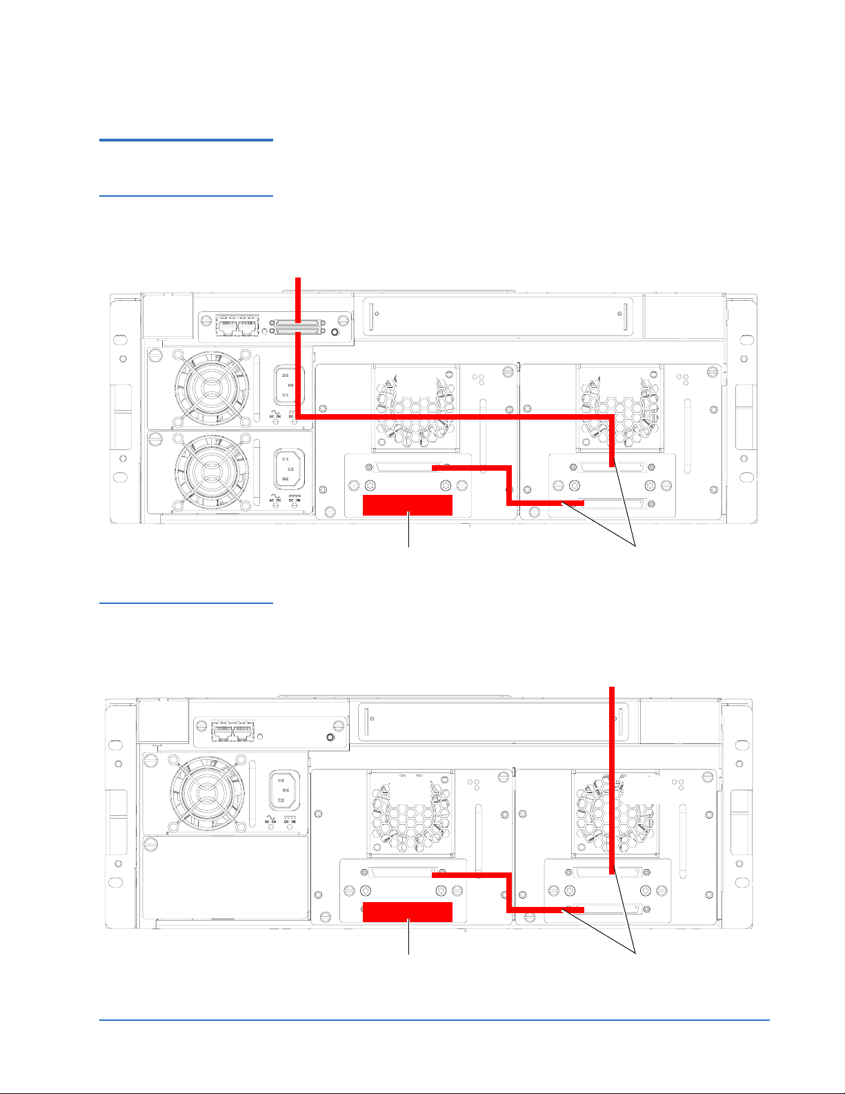
PX502 Libraries 0 The following figures illustrate tape drive cabling for the PX502 libraries
Figure 5 Cabling the Tape
Drives in a PX502 Library
(SCSI)
Host computer
Figure 6 Cabling the Tape
Drives in a PX502 Library
(SCSI Surrogate)
Tape
drive 2
SCSI terminator
Tape
drive 1
SCSI jumper cables
Host computer
Tape
drive 2
SCSI terminator
SCSI jumper cables
Tape
drive 1
Cabling the Tape Drives 9
Page 10

Quantum PX500 Series Tape Drive Installation Instructions
81-81301-04 A01
August 2006
Figure 7 Cabling the Tape
Drives in a PX502 Library
(Native Fibre Channel)
Fibre Channel host/SAN
LTO-2, -3 native Fibre Channel drives
shown. SDLT 600 and DLT-S4 native
Fibre Channel drives have only one
FC port
Tape
drive 2
Fibre Channel host/SAN
Tape
drive 1
Fibre Channel host/SAN
10 Cabling the Tape Drives
Page 11
Quantum PX500 Series Tape Drive Installation Instructions
81-81301-04 A01
August 2006
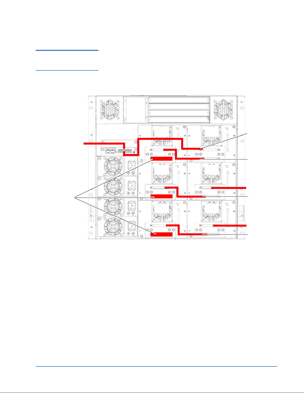
PX506 Libraries 0 The following figures illustrate tape drive cabling for the PX506 library.
Figure 8 Cabling the Tape
Drives in a PX506 Library
(SCSI)
Host computer
SCSI
terminators
Tape
drive 2
Tape
drive 4
Tape
drive 6
Tape
drive 1
Tape
drive 3
Tape
drive 5
SCSI
jumper
SCSI jumper
Host computer
SCSI jumper
Host computer
SCSI jumper
Cabling the Tape Drives 11
Page 12

Quantum PX500 Series Tape Drive Installation Instructions
81-81301-04 A01
August 2006
Figure 9 Cabling the Tape
Drives in a PX506 Library
(Native Fibre Channel)
Fibre Channel
host/SAN
LTO-2, -3 native
Fibre Channel
drives shown. SDLT
600 and DLT-S4
native Fibre
Channel drives have
only one FC port
Tape
drive 2
Tape
drive 4
Tape
drive 6
Tape
drive 1
Fibre Channel
host/SAN
Tape
drive 3
Fibre Channel
host/SAN
Tape
drive 5
Fibre Channel
host/SAN
12 Cabling the Tape Drives
Page 13

Quantum PX500 Series Tape Drive Installation Instructions
81-81301-04 A01
August 2006
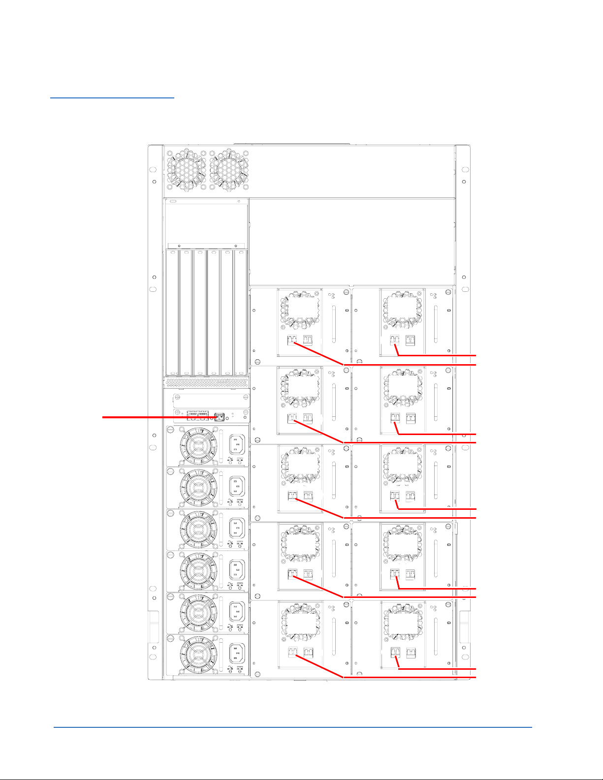
PX510 Libraries 0 The following figures illustrate tape drive cabling for the PX510 library.
Figure 10 Cabling the
Tape Drives in a PX510
Library (SCSI)
SCSI jumper
Host computer
SCSI
terminators
Tape
drive 2
Tape
drive 4
Tape
drive 6
Tape
drive 8
Tape
drive 1
Tape
drive 3
Tape
drive 5
Tape
drive 7
SCSI
jumper
Host computer
SCSI
jumper
Host computer
SCSI
jumper
Host computer
Tape
drive 10
Tape
drive 9
SCSI
jumper
Host computer
Cabling the Tape Drives 13
Page 14
Quantum PX500 Series Tape Drive Installation Instructions
81-81301-04 A01
August 2006
Figure 11 Cabling the Tape
Drives in a PX510 Library
(Native Fibre Channel)
Fibre Channel
host/SAN
Tape
drive 2
Tape
drive 4
Tape
drive 6
Tape
drive 8
Tape
drive 1
Fibre Channel
host/SAN
Tape
drive 3
Fibre Channel
host/SAN
Tape
drive 5
Fibre Channel
host/SAN
Tape
drive 7
LTO-2, -3 native Fibre
Channel drives
shown. SDLT 600 and
DLT-S4 native Fibre
Channel drives have
only one FC port
Tape
drive 10
14 Cabling the Tape Drives
Fibre Channel
host/SAN
Tape
drive 9
Fibre Channel
host/SAN
Page 15
Quantum PX500 Series Tape Drive Installation Instructions
81-81301-04 A01
August 2006
Setting the Tape Drive SCSI ID 0
The next step in the installation procedure is to set the required SCSI ID for
the new tape drive.
Note: The library assigns SCSI IDs based on the drive order. Drive bay
1 = SCSI ID 1, drive bay 2 = SCSI ID 2, and so forth. It is only
necessary to perform the steps in this section if you need to set the
tape drive SCSI ID to an ID other than the default.
There are two ways to set the tape drive SCSI ID:
• Setting the SCSI ID Using the OCP
• Setting the SCSI ID from the Remote Management Pages
Setting the SCSI ID Using the OCP
Figure 12 Setup Screen
Figure 13 Library Options
Screen
To set the tape drive SCSI ID on an PX500 Series library with an LCD:
0
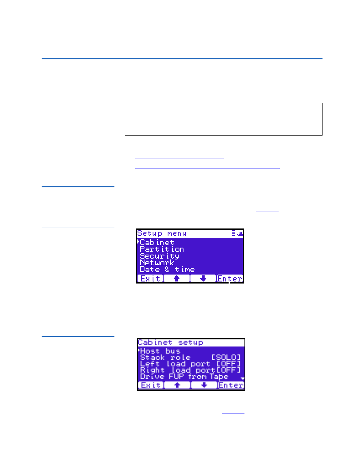
1 From the operator control panel (OCP), press
screen. The OCP displays the
Setup screen (see figure 12):
Enter
Setup from the Home
2 Use the up and down arrows to highlight Cabinet and press Enter.
The
Cabinet screen displays (see figure 13):
3 Use the up and down arrows to highlight Host bus and press Enter.
The
Host bus screen displays (see figure 14):
Setting the Tape Drive SCSI ID 15
Page 16
Quantum PX500 Series Tape Drive Installation Instructions
81-81301-04 A01
August 2006
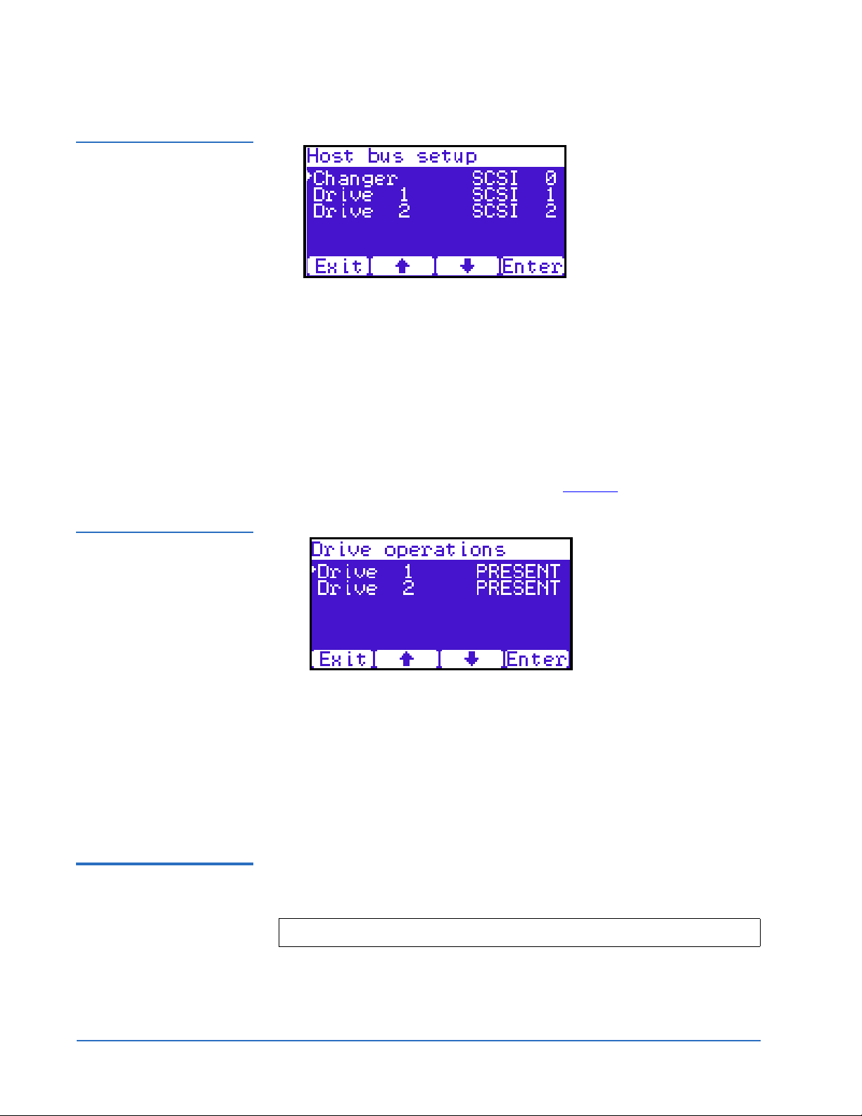
Figure 14 Host Bus
Options Screen
4 Use the up and down arrows to highlight the tape drive receiving the new
SCSI ID and press
Enter.
Figure 15 Drive
Operations Screen
5 Use the up and down arrows to select a SCSI ID and press
Enter to set the
ID.
6 When you have completed setting the SCSI IDs, press
Cabinet screen.
7 From the
Operations
The
Ops screen, use the up and down arrows to highlight Drive
and press Enter.
Drive Operations screen displays (see figure 15):
Exit to return to the
8 Use the up and down arrows to select a tape drive and press Enter.
9 Use the up and down arrows to select
The tape drive powers down and returns to the
Off and press Enter.
Drive Operations screen.
10 Use the up and down arrows to select
The tape drive powers on and is ready for use. The tape drive installation
is complete.
Setting the SCSI ID from the Remote Management Pages
0
To set the tape drive SCSI ID on a PX500 Series library from the remote
management pages:
Note: The library must be off-line during this procedure.
1 On the host computer, open the internet browser software.
2 In the
Address field, type http://IPaddress/ where IP address is the IP
address for the Quantum PX500 Series library.
16 Setting the Tape Drive SCSI ID
On and press Enter.
Page 17

Figure 16 Overview Page
Banner area
Quick status
Navigation area
Content area
Quantum PX500 Series Tape Drive Installation Instructions
3 Enter the username and password and click OK.
Note: The default username and password is admin.
The
Overview page displays (see figure 16):
81-81301-04 A01
August 2006
Figure 17 SCSI Page
4 Click the Setup tab.
The
Setup tab displays.
5 Click on the
The
SCSI page displays (see figure 17).
SCSI tab at the top of the Setup tab.
Setting the Tape Drive SCSI ID 17
Page 18

Quantum PX500 Series Tape Drive Installation Instructions
81-81301-04 A01
August 2006
6 To change a SCSI ID, enter the ID number in the field next to the device
and click
Apply.
Figure 18 Drives Page
Drive operations
7 From the
The
Operations page, click on the Drives tab.
Drives page displays (see figure 18):
8 Enter the new tape drive number
9 Select
shutdown and click Apply.
The tape drive powers down.
10 Enter the new tape drive number
11 Select
Power on and click Apply.
The tape drive powers on. The tape drive installation is complete.
Completing the Native Fibre Channel Installation 0
After native Fibre Channel tape drives are installed, additional information
must be gathered to complete the installation and verify connectivity.
Competing the native Fibre Channel tape drive installation consists of the
following steps:
• Determining the WWNs World Wide Names
• Verifying Library Connectivity
Determining the WWNs World Wide Names
0
The media changer (robot) and tape drives within the library have WWNs
World Wide Names assigned to them by the system controller board (SCB).
The WWNs must be determined and recorded both for the customer and for
18 Completing the Native Fibre Channel Installation
Page 19

Quantum PX500 Series Tape Drive Installation Instructions
81-81301-04 A01
August 2006
Quantum customer support. This information is important when replacing
the Fibre Channel SCB and tape drives. Using the following procedures,
complete table 2
and retain a copy of the table for your records. Have this
table available when contacting Quantum Customer Support for any library
or tape drive connectivity issues.
Table 2 Library World
Wide Names
Library/Tape Drive World Wide Name (e.g. 50:05:08: 40:00:16:47:00)
Media Changer
(robot)
Tape drive 1
Tape drive 2
Tape drive 3
Tape drive 4
Tape drive 5
Tape drive 6
Tape drive 7
Tape drive 8
Tape drive 9
Tape drive 10
Using the Remote Management to Determine the WWNs 0
To determine the WWNs from the library remote management pages:
1 On the host computer, open the internet browser software.
2 In the
Address field, type http://IPaddress/ where IP address is the IP
address for the Quantum PX500 series library.
3 Enter the username and password and click
Note: The default username and password is
The
Overview page displays (see figure 19):
Completing the Native Fibre Channel Installation 19
OK.
admin.
Page 20

Quantum PX500 Series Tape Drive Installation Instructions
81-81301-04 A01
August 2006
Figure 19 Overview Page
4 Click Setup from the contents frame.
Figure 20 Setup Page
The management frame displays the
5 Click on the SCSI/Fibre tab.
The
SCSI/Fibre page displays (see figure 21).
Setup page (see figure 20).
20 Completing the Native Fibre Channel Installation
Page 21

Figure 21 SCSI/Fibre
Page
Quantum PX500 Series Tape Drive Installation Instructions
81-81301-04 A01
August 2006
Media changer
Tape drives
Figure 22 Media Changer
Configuration Screen
Connectivity
type
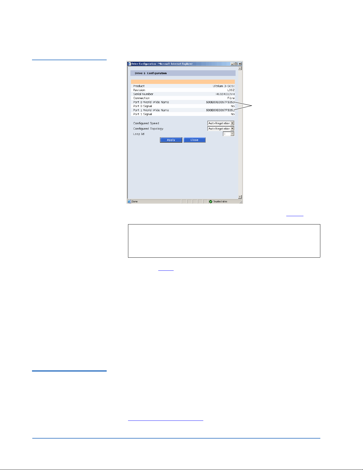
6 For the Media Changer and Tape Drives, click Fibre under the Connectivity
type
.
The
Media Changer (see figure 22) and Tape Drive Configuration (see
figure 23
) screen displays.
World wide name
Completing the Native Fibre Channel Installation 21
Page 22
Quantum PX500 Series Tape Drive Installation Instructions
81-81301-04 A01
August 2006
Figure 23 Tape Drive
Configuration Screen
World wide names
(port 0 and port 1)
Verifying Library Connectivity
7 Record the WWNs for the media changer and tape drives in table 2.
Note: These numbers are the world wide NODE names for the
library and tape drives. The World Wide Port Name is very
similar to the World Wide Node Name, however, the last hex
byte is 01h greater than the last hex byte of the node name.
• Repeat step 6
for all tape drives in the library
or
•Add
04h to the last hex byte to derive the WWN for the next tape
drive.
Example:
50:05:08:40:16:6B:
8 To determine the WWN for the media changer, subtract
to last hex byte of the WWN for
Example:
be 50:05:08:40:16:
Drive 0 WWN is 50:05:08:40:16:6B:00, Drive 1 WWN will be
04, Drive 2 WWN will be 50:05:08:40:16:6B:08.
01h from the next
Drive 0.
Drive 0 WWN is 50:05:08:40:16:6B:00, Media Changer WWN will
6A:00.
To verify the tape drive installation, you should verify that the library and
0
tape drives are recognized from the host or from the SAN switch.
If the SAN switch is available, it is possible to verify connectivity by
connecting to the switch. There are two ways to directly access the SAN
switch:
• Connect Via a Telnet Session
22 Completing the Native Fibre Channel Installation
Page 23
Quantum PX500 Series Tape Drive Installation Instructions
81-81301-04 A01
August 2006
• Connect Via a Web Browser
Note: The information below applies to a Brocade SAN switch. For other
SAN switches, contact the SAN administrator.
Connect Via a Telnet Session 0
To connect via a Telnet session to a SAN switch:
1 Connect the service laptop to the SAN switch using an Ethernet cross-
over cable, or by connecting to the LAN (if available).
2 On the service laptop, open a command prompt window.
3 From the command prompt, enter the following command and press
<Enter>:
telnet <IP address of SAN switch>
The SAN switch login prompt displays.
Figure 24 Nsshow
Command
4 Enter the
username and password and press <Enter>.
Note: For Brocade SAN switches, the default login is admin for the
username and
password for password. This may have been
changed by the system administrator. For all other switches,
contact the system administrator.
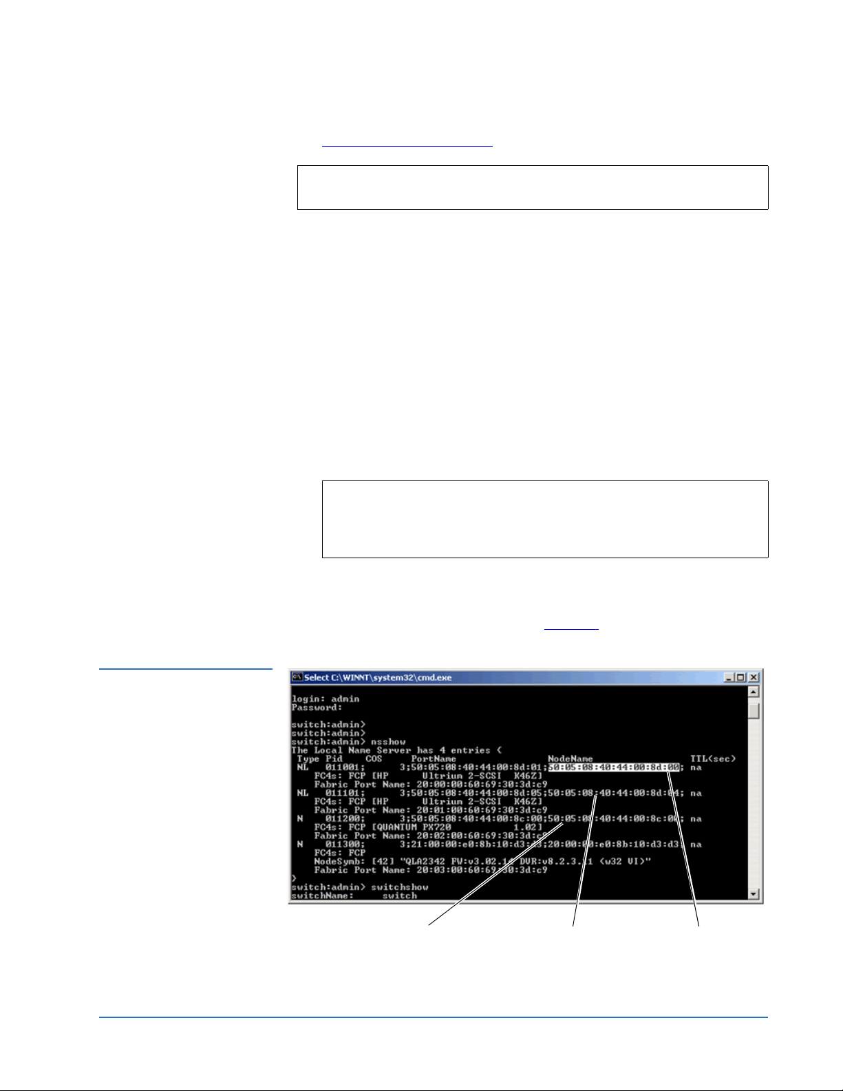
5 For Brocade switches, at the command prompt, type
nsshow and press
<Enter>.
The nsshow command displays (see figure 24
).
WWN for the library
Completing the Native Fibre Channel Installation 23
WWN for the second
Native Fibre channel
drive
WWN for the first
Native Fibre channel
drive
Page 24

Quantum PX500 Series Tape Drive Installation Instructions
81-81301-04 A01
August 2006
If the world wide names are visible from the nsshow command, the
connectivity is verified.
Connect Via a Web Browser
To connect via a web browser:
1 Connect the service laptop to the SAN switch using an Ethernet cross-
over cable.
2 On the service laptop, launch a web browser such as Internet Explorer.
3 In the
4 Examine the Name Server table for the status of the switch ports and the
Address field, type http://IPaddress/ where IP address is the IP
address for the SAN switch and press <Enter>.
The SAN switch web based utility displays.
WWNs of the connected devices.
If the WWNs for the library and all tape drives are visible, the
connectivity is verified.
Fibre Channel Connectivity Troubleshooting 0
Refer to the following sections Fibre Channel connectivity troubleshooting:
• Fibre Channel Connectivity Troubleshooting
0
Fibre Channel Connectivity Troubleshooting
• SCSI ID Assignment with Native Fibre Channel Tape Drives
0
The following section provides Fibre Channel connectivity problems and
resolutions when connecting via Fibre Channel to the SAN switch, or directly
to the library and drives.
1 Medium changer and drives are not visible in the device manager
a Check all cable connections.
b Check the SAN switch port LEDs for connection status to the library
Fibre Channel HBA and tape drives.
c If you are connected to the SAN switch, verify that you are connected
to the same zone as the library and tape drives. If you are unsure, try
one of the ports on the SAN switch that a tape drive is connected to.
Note: If you are not on a port in the same zone as the library and all
of the drives, you will not be able to verify connectivity.
d Verify that the SAN switch is powered on and operating normally.
24 Fibre Channel Connectivity Troubleshooting
Page 25
Quantum PX500 Series Tape Drive Installation Instructions
81-81301-04 A01
August 2006
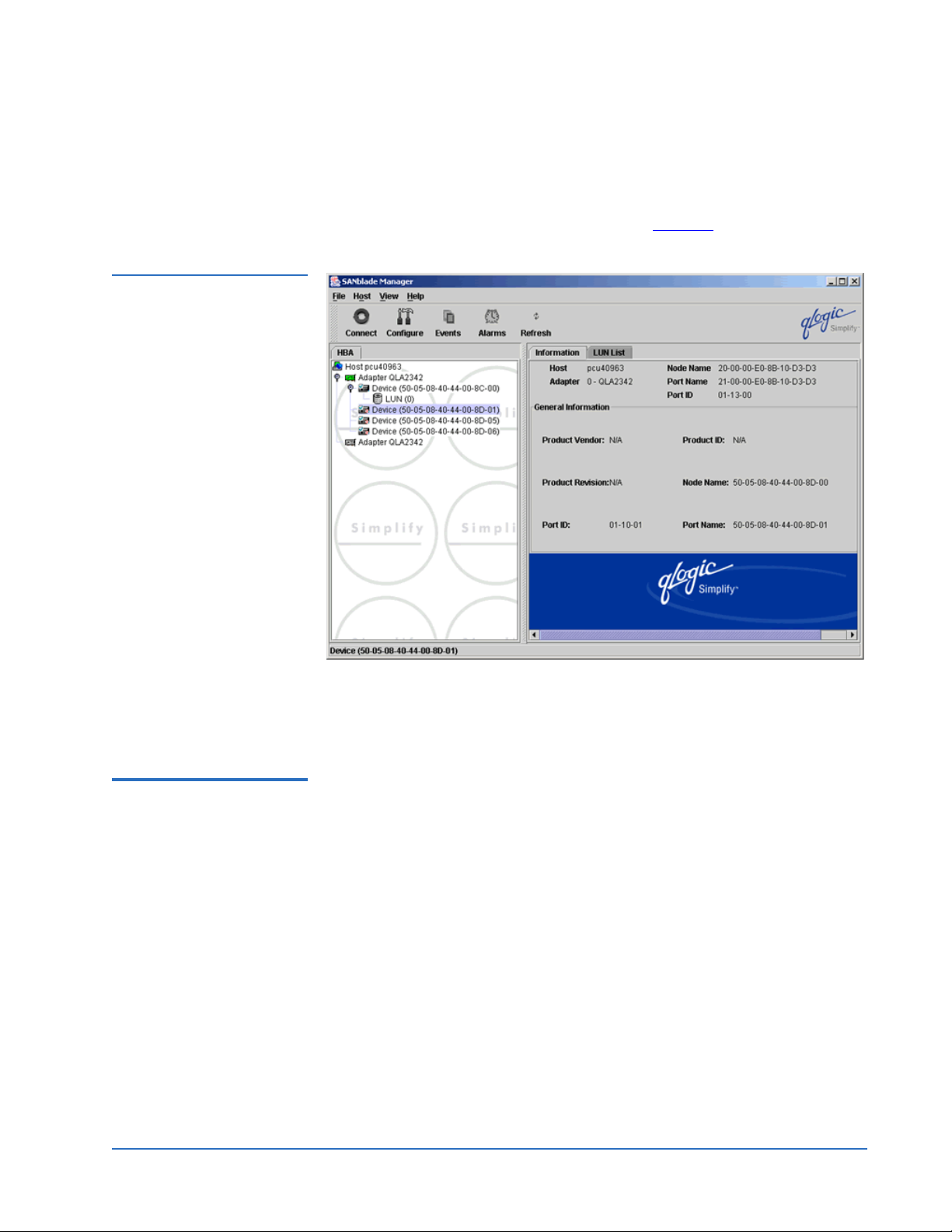
e If you are still unable to view the Fibre Channel devices, launch the
SANsurfer SANblade manager and click Connect. Accept the default
“localhost” entry.
Figure 25 SANblade
Manager
The SANblade manager displays (see figure 25
).
SCSI ID Assignment with Native Fibre Channel Tape Drives
The SANblade manager should display all connected Fibre Channel
devices. If the library and tape drives do NOT display, check the
cabling and connection status.
With native Fibre Channel tape drives, each tape drive is it’s own Fibre
Channel target with a dedicated WWN and on LUN 0. The host (including
0
the laptop using MAGMA box) will pick up the devices and assign local SCSI
IDs in the order that the SAN devices are discovered. This will in almost
every case NOT match the order of the devices as they are installed in the
library. This is not a problem from the customer point of view, as long as
drive serialization is enabled on the library and serialization is supported by
the customers ISV application. This will allow the ISV application to put the
drives in the correct order within the application.
In some rare cases it may be necessary to re-map the local SCSI ID
assignments so that the library changer is at SCSI ID 0 and the drive SCSI ID
assignments follow in order. The important thing to remember is that the
order of the SCSI IDs on your system will probably not match the order of the
drives in the library. Make sure to check the SCSI ID that is assigned to the
WWN of the drive you want to communicate with or you may be
communicating to the wrong drive
Fibre Channel Connectivity Troubleshooting 25
Page 26

Quantum PX500 Series Tape Drive Installation Instructions
81-81301-04 A01
August 2006
To display the SCSI ID assignments:
Figure 26 Port
Configuration Screen
1 From the SANblade manager program, click
The port configuration screen displays (see figure 26
Configure.
).
SCSI ID
assignment
The port configuration screen allows you to change the SCSI ID order if
the Fibre Channel HBA drive supports persistent bindings.
Click on the drop down ID box to change the SCSI ID assignment as
desired.
26 Fibre Channel Connectivity Troubleshooting
 Loading...