

Page 1

Declaration of Conformity
QUANTUM DESIGNS(HK) L TD.
20th Floor, Devon House, Taikoo Place, 979 King’s Road,
Quarry Bay, Hong Kong
declares that the product
Motherboard
PlatiniX 2
is in conformity with
(reference to the specification under which conformity is declared in
accordance with 89/336 EEC-EMC Directive)
!"EN 55022 Limits and methods of measurements of radio disturbance
characteristics of information technology equipment
!"EN 50081-1 Generic emission standard Part 1:
Residential, commercial and light industry
!"EN 50082-1 Generic immunity standard Part 1:
Residential, commercial and light industry
European Representative:
QDI COMPUTER( UK ) L TD. QDI COMPUTER( SCANDINAVIA )A/S
QDI SYSTEM HANDEL GMBH QDI EUROPE B.V
QDI COMPUTER( FRANCE ) SARL QDI COMPUTER HANDELS GMBH
LEGEND QDI SPAIN S.L. QDI COMPUTER( SWEDEN )AB
Signature : Place / Date : HONG KONG/2001
Printed Name : Xu Wenge Position/ Title : Assistant President
Page 2

Declaration of Conformity
Trade Name: QDI Computer ( U. S . A. ) Inc.
Model Name: PlatiniX 2
Responsible Party: QDI Computer ( U. S. A.) Inc.
Address: 41456 Christy Street
Fremont, CA 94538
Telephone: (510) 668-4933
Facsimile: (510) 668-4966
Equipment Classification: FCC Class B Subassembly
Type of Product: Motherboard
Manufacturer: Quantum Designs (HK) Inc.
Address: 20th Floor, Devon House, Taikoo Place
979 King’s Road, Quarry Bay, HONG
KONG
Supplementary Information:
This device complies with Part 15 of the FCC Rules. Operation is subject to
the following two conditions : (1) this device may not cause harmful interference, and (2) this device must accept any interference received, including
interference that may cause undesired operation.
Tested to comply with FCC standards.
Signature : Date : 2001
Page 3

CONTENTSCONTENTS
CONTENTS
CONTENTSCONTENTS
1. Introduction................................................ 1
Overview........................................................................1
Key Features ..................................................................1
2. Instal latio n Inst ructi ons ............................. 4
External Connectors .............................................. 4
PS/2 Keyboard /Mouse Connector ...................................4
USB1, USB2 and LAN Connectors...................................4
Parallel Port, Serial Port Connectors................................... 4
Line-in jack, Mic-in jack, Speaker-out jack and MIDI/Joystick
Connector............................................................................5
ATX 12V Power Supply Connectors & Power Switch......5
Hard Disk LED Connector ( HD_LED )...............................6
Reset Switch ( RESET )...................................................6
Speaker Connector ( SPEAKER ) .....................................6
Power LED Connector( PWR_LED ) .................................6
Green LED Connector( GREEN_LED ) ..............................6
ACPI LED Connector( ACPI_LED ) ....................................6
Hardware Green Connector ( SLEEP SW ) ...................... 6
Key Lock Connector( KEYLK ) ........................................6
USB3, 4...........................................................................7
Infrared Header ( IrDA )...................................................7
Sound Connector( PC-PCI )..............................................7
Fan Connectors( CPUF AN , CHSFAN, PWRF AN )..............8
Intruder Detect Switch( JINTR )........................................8
Wake-Up On LAN ( WOL ) ...............................................9
Wake-Up On Internal Modem ( WOM ) ..............................9
Audio Connectors ( AUXIN, CD_IN, MODEM )....................10
4-pin SMBus Connector( SMBUS ).....................................10
Chassis Security Switch( CHSSEC )..................................1 1
Communication and Networking Riser Slot( CNR )..............11
Audio Interface....................................................................12
Jumper Settings.............................................................13
BIOS-ProtectEasy Jumper( JA V )........................................13
Overclocking Jumper Setting( JFS1 )..................................14
II
Page 4

CONTENTSCONTENTS
CONTENTS
CONTENTSCONTENTS
Clear CMOS( JCC ).......................................................15
CPU Core Voltage Setting( JVID0~4 )............................15
Enable Front/Back Panel USB Device Wake-up Function
( JUSB, JFUSB )............................................................17
Enable/Disable onboard Audio( JSD )...........................17
Enable keyboard password power-on function(JKB)..18
3. BIOS Description..................................19
Utility Support...........................................................19
AWDFLASH.EXE ..........................................................19
A WARD BIOS Description......................................20
Entering Setup ..............................................................20
Load Optimized Defaults ..............................................20
Standard CMOS Features Setup...................................20
CPU SpeedEasy Setup..................................................24
Advanced BIOS Features Setup...................................25
Advanced Chipset Features Setup...............................27
Power Management Setup............................................29
PnP/PCI Configurations Setup........................................32
Integrated Peripherals...................................................33
PC Health Status............................................................36
Password Setting..........................................................38
Boot with BIOS defaults................................................38
Appendix
QDI Driver CD...........................................................A.1
ManageEasy ............................................................A.2
BIOS-ProtectEasy.....................................................A.2
Norton AntiVirus.......................................................A.2
LogoEasy...................................................................A.3
SpeedEasy.................................................................A.4
BootEasy....................................................................A.6
RecoveryEasy............................................................A.10
StepEasy....................................................................A.18
PlatiniX 2( Francais ).............................................A.20
Layout
II
Page 5

Chapter 1
Chapter 1
Chapter 1
Introduction
Introduction
Overview
PlatiniX 2 series of green mainboards utilize Intel® 845 chipset consisting of two components: the Intel
troller Hub2(ICH2), providing a fully compatible, high performance and cost-effective PC/
A TX platform. The new integrated technologies, together with AGP 4X support, AC’97
audio(optional, Upgradable to 6 channels audio with CNR card), integrated LAN(optional),
4 USB ports, and A TA100/66/33, give customers an advanced, multimedia solution at an
reasonable price. It provides 400MHz host bus speed to support Intel
478 processors. It also provides advanced features such as Wake up by USB devices,
Wake-on-LAN, Wake-on-Modem, ACPI and Keyboard Password Power-on functions.
Suspend to RAM, the optimal implementation of the Advanced Configuration and Power
Interface (ACPI) specification, makes the PC’s power consumption drop to the lowest
possible level and enable quick wakeup. ManageEasy , our system management applica-
tion is also supplied to enable remote monitoring and configuration of the system. BootEasy ,
lets the PC boot freely and rapidly . StepEasy(optional), our new innovation is also supplied
to enable you to adjust CPU frequency step by step easily to meet your need.
®
i845 Memory Controller Hub(Brookdale MCH) and the 82801BA I/O Con-
®
Pentium 4 socket
Key Features
Form factor
#"A TX form factor of 305mm x 224mm
Microprocessor
#"Supports Intel
#"Supports 400MHz host bus speed
®
Pentium 4 socket 478 processors at 1.4/1.5/1.7/1.8GHz and above
System memory
#"Provides three 168-pin, 133MHz SDRAM interfaces
#" Supports PC133 SDRAM
#"Supports up to 384MB using 64Mb technology
#"Supports up to 1.5GB using 256Mb technology
#"Supports up to 3GB using 512Mb technology
Onboard IDE
#"Supports Independent timing of up to 4 drives
#"Supports Ultra A T A 100/66/33, PIO mode
#"Implements Write Ping-Pong Buffer for faster write performance
#"Two fast IDE interfaces supporting four IDE devices including IDE hard disks and CD
ROM drives
Manual for PlatiniX 2 series
Page 6

Introduction
Onboard LAN (available on PlatiniX 2-L/-AL, PlatiniX 2I-L/-AL)
#"10/100 Mbit/sec Ethernet support
#"10/100M LAN interface built-in on board
4 USB
#"USB 1.1 compliant
#"Supports wake-up from S1 (power on suspend), S3 (STR) (depend on device)
Onboard I/O
#" Winbond W83627 HF-AW I/O chip
#"One floppy port supporting up to two 3.5
″
or 5.25″ floppy drives with 360K/720K/1.2M/
1.44M/2.88M format
#" Two high speed 16550 compatible UART (COM1/COM2/COM3/COM4 selective) with 16
byte send/receive FIFO
#" One parallel port supports SPP/EPP/ECP mode
#"Infrared interface
#" All I/O ports can be enabled/disabled in the BIOS setup
Onboard Audio(available on PlatiniX 2-A/-AL, PlatiniX 2I-A/-AL)
#" AC’97 2.1 Specification Compliant
#"16bit stereo codec
#"Multiple stereo input mixer
#"Mono and stereo volume control
#"Provides onboard Line-in Jack, Microphone-in Jack, Speaker-out Jack with onboard
amplifier and MIDI/Joystick Connector
#"Upgradable to 6 channels audio with CNR card
AGP Interface
#"AGP 1.5V Connector supports AGP 2.0 including AGP 4x data transfers
Advanced features
#" PCI 2.2 Specification Compliant
#"Provides Trend ChipAwayVirus On Guard
#"Supports Windows 98/2000/ME soft-off
#" Supports Wake-on-LAN and Wake-on-Modem
#"Supports Keyboard Password Power-on function
#" Supports system monitoring(monitors CPU and system temperatures, system
voltages, fan speed)
#" Providing QDI innovations: StepEasy(optional), SpeedEasy, RecoveryEasy ,
BIOS-ProtectEasy , LogoEasy, ManageEasy, BootEasy
Manual for PlatiniX 2 series
Page 7

Chapter 1
BIOS
#"Licensed advanced AWARD(Phoenix) BIOS, supports flash ROM with 2Mb memory
size, plug and play ready
#"Supports IDE CD-ROM or SCSI boot up
Green function
#"Supports ACPI (Advanced Configuration and Power Interface) and ODPM (OS
Directed Power Management)
#"Supports ACPI power status: S0 (full-on), S1 (power on suspend), S3 (STR),
S4(STD)(Windows Me, Windows 2000) and S5 (soft-off)
Main Expansion Slots and Connectors
Slot/Port ( Quantity ) Description
IDE( 2 ) IDE ports
FLOPPY( 1 ) Floppy drive port
DIMM( 3 ) SDRAM DIMM slots
USB( 4 ) USB connectors
AGP( 1 ) AGP slot
IrDA( 1 ) IrDA connector
PCI( 6 )( optional ) PCI slots
ISA( 1 )( optional ) ISA slot
LAN( 1 )( optional ) LAN connector
MIDI/Joystick( optional ) MIDI/Joystick connector
Manual for PlatiniX 2 series
Page 8

T-- This page is intentionally left blank --his
Page 9

Chapter 2
Chapter 2
Chapter 2
Installation Instructions
Installation Instructions
This section covers External Connectors and Jumper Settings. Refer to the mainboard
layout chart for locations of all jumpers, external connectors, slots and I/O ports. Furthermore, this section lists all necessary connector pin assignments for your reference. The
particular state of the jumpers, connectors and ports are illustrated in the following figures. Before setting the jumpers or inserting these connectors, please pay attention to the
directions.
Be sure to unplug the AC power supply before adding or removing expansion
cards or other system peripherals, otherwise your mainboard and expansion
cards might be seriously damaged.
External Connectors
PS/2 Keyboard/Mouse Connector
PS/2 keyboard connector is for the usage of PS/2 keyboard. If using a standard AT size
keyboard, an adapter should be used to fit this connector. PS/2 mouse connector is for the
usage of PS/2 mouse.
PS/2 Mouse Connector
PS/2 Keyboard Connector
USB1, USB2 and LAN Connectors
(LAN connector is only available on PlatiniX 2-L/-AL, PlatiniX 2I-L/-AL)
Two USB ports are for connecting USB devices. The RJ-45 connector is for onboard LAN.
LINK Active
LAN(optional)
USB1
USB2
Parallel Port, Serial Port Connectors (UART1, UART2)
The parallel port connector can be connected to a parallel device such as a printer. The serial
port UART1,2 connectors can be connected to a serial port device such as a serial port
mouse. Y ou can enable/disable them and choose the IRQ or I/O address in “Integrated Peripherals” from AW ARD CMOS SETUP .
Parallel Port
UART1
Manual for PlatiniX 2 series
UART2
Page 10

Installation Instructions
Line-in jack, Microphone-in jack, Speaker-out jack and MIDI/Joystick
Connector (available on PlatiniX 2-A/-AL, PlatiniX 2I-A/-AL)
The Line-in jack can be connected to devices such as a cassette or minidisc player to
playback or record. The Microphone-in jack can be connected to a microphone for voice input.
The Speaker-out jack allows you to connect speakers or headphones for audio output from
the internal amplifier.The MIDI/Joystick connector allows you to connect a game joystick or a
MIDI device.
MIDI/Joystick
Optional
Speaker out Line in Microphone in
A TX12V Power Supply Connectors & Power Switch (POWER SW)
The PlatiniX 2 series of mainboards must use ATX12V power supply . Be sure to connect the
ATX 12V power supply plugs to the connectors in their proper orientation. The difference
between ATX12V power supply and ATX power supply is that ATX12V power supply
provides two additional power connectors: AUX power connector and +12V power connector.
The power switch (POWER SW) should be connected to a momentary switch. When
powering up your system, first turn on the mechanical switch of the power supply (if one
is provided), then push once the power switch. When powering off the system, you
needn’t turn off the mechanical switch, just
Push once
*
the power switch.
12V 12V
+12V Power Supply Connector
GND
ATX Power Supply Connector
GND GND PS-ON -12V 3.3V
GND
5V GND PW-OK 3.3V
5V GND
GND
AUX Power Supply Connector
GND 3.3V 3.3V GND GND 5V
GND
1
3.3V
POWER
SW
1
GND
5V 5 V -5V
20
12V 5VSB
1
Note: * If you change “soft-off by PWR-BTTN” from default “Instant-off” to “Delay
4 Sec” in the “POWER MANAGEMENT SETUP” section of the CMOS SETUP, the
power button should be pressed for more than 4 seconds before the system
powers down.
Manual for PlatiniX 2 series
Page 11

Chapter 2
Hard Disk LED Connector (HD_LED)
The connector connects to the case’s IDE indicator LED indicating the activity status of IDE
hard disk. The connector has an orientation. If one way doesn’t work, try the other way.
Reset Switch (RESET)
The connector connects to the case’s reset switch. Press the switch once, the system
resets.
Speaker Connector (SPEAKER)
The connector can be connected to the speaker on the case.
Power LED Connector (PWR_LED)
When the system is in power up status, the LED is on. When the system is in suspend
status, the LED is blink. When the system is in suspend to RAM, the LED is off. When the
system is in soft-off status, the LED is off. The connector has an orientation.
GREEN LED Connector (GREEN_LED)
When the system is in power up, ACPI suspend or soft-off status, the LED is off. When the
system is in suspend to RAM status, the LED is on.
ACPI LED Connector (ACPI_LED)
The ACPI LED is a dual-color light with three pins. Pin1and Pin2 drive different color lights. If
Pin1 drives the orange light , then, Pin2 drives the green light, the following status will come
out. When the system is in power up status, the LED is green on. When the system is in
suspend status, the LED is green blink. When the system is in Suspend to RAM status, the
LED is orange on. When the system is in soft-off status, the LED is off.
Hardware Green Connector (SLEEP SW)
Push once the switch connected to this header, the system enters suspend mode.
Key Lock Connector (KEYLK)
The connector can be connected to the keyboard lock switch on the case for locking the
keyboard.
HD_LED
ACPI_LED
SPEAKER
POWER
SW
SLEEP
SW
PWR_LED
Manual for PlatiniX 2 series
ACPI_LED
POWER
SW
RESET GREEN_LED
SLEEP
SW
PWR_LED
KEYLK
HDD LED(+)
ORANGE(-)
GREEN(-)
LED+
POWER
GND
EMPTY
EMPTY
SLEEP
GND
LED+
LED-
LED- KEYLOCK
HDD LED(-)
VCC
GND
NC
SPKDA TA
RESET
GND
EMPTY
LED+
LEDLEDGND
SPEAKER
RESET
GREEN_LED
KEYLK
Page 12

Installation Instructions
USB3, USB4
Besides USB1,2 on the back panel, PlatiniX 2 series of mainboards also have a 10-pin header
on board which may connect to front panel USB cable( optional ) to provide additional two USB
ports.
+5V
D3-
D3+
GND
GND
GND
GND
D4+
D4 +5V
USB3,4
Infrared Header (IrDA)
This connector supports wireless transmitting and receiving device. Before using this
function, configure the settings for IR Address, IR Mode and IR IRQ from the “INTEGRA TED
PERIPHERALS” section of the CMOS SETUP .
VCC
NC
IRRX
GND
IRTX
VCC
IrDA
Sound Connector (PC-PCI)
This connector provides a bridge between the mainboard and PCI sound card to deliver
sound compatibility under DOS real-mode environment.
Manual for PlatiniX 2 series
GND
PC-PCI DMA REQUEST
SERIAL INTERRUPT REQUEST
PC-PCI
GND
NC
PC-PCI DMA ACKNOWLEDGE
Page 13

Chapter 2
Fan Connectors (PWRFAN, CPUF AN, CHSF AN)
The fan speed of these three fans can be detected and viewed in “PC Health” section of
the CMOS SETUP. These three fans will be automatically turned off after the system
enters suspend mode.
GND
+12V
CPUFAN
SENSE
GND
SENSE
+12V
PWRFAN
GND
+12V
CHSFAN
SENSE
Intruder Detect Switch(JINTR)(Reserved)
The connector connects to the chassis security switch on the case. The system can
detect the chassis intrusion through the status of this connector. If the connector has
been closed once, the system will send a message over the network to alert the network
manager through the on board LAN controller within ICH2.
Manual for PlatiniX 2 series
Indicate signal
GND
JINTR
Page 14

Installation Instructions
Wake-Up On LAN (WOL)
Through the Wake-Up On LAN function, a wake event occurring from the network can
wake up the system. If this function is to be used, please be sure an ATX12V power
supply of which 5VSB line is capable of delivering 720mA, and a LAN adapter which
supports this function is used. Then connect this header to the relevant connector on the
LAN adapter, set “Wake-Up by Ring/LAN” as Enabled in the “POWER MANAGEMENT
SETUP” section of the CMOS SETUP. Save and exit, then boot the operating system once
to make sure this function takes effect.
+5V standby
GND
Signal for waking up (active high)
WOL
Wake-Up On Internal Modem (WOM)
Through this function, the system which is in the suspend or soft-off status can be
waked up by a ring signal received from the internal modem. When this function is used,
be sure an internal modem card which supports this function is used. Then connect this
header to the relevant connector on the modem card, set “Wake-Up by Ring/LAN” as
Enabled in the “Power Management Setup” section of the CMOS SETUP . Save and exit,
then boot the operating system once to make sure this function takes effect.
Manual for PlatiniX 2 series
+5V standby
Signal for waking up (active low)
GND
WOM
Page 15

Chapter 2
Audio Connectors (CD_IN, MODEM, AUXIN)
(available on PlatiniX 2-A/-AL, PlatiniX 2I-A/-AL)
CD_IN is a Sony standard CD audio connector, it can be connected to a CD-ROM drive
through a CD audio cable. The MODEM connector allows the onboard audio to interface
with a voice modem card with a similar connector. It allows connecting the mono_in (such
as a phone) or mono_out (such as a speaker) between the onboard audio and the voice
modem card. AUXIN allows you to receive stereo audio input from sound sources such as
a CD-ROM,TV tuner,or MPEG card.
CD Right Channel
Common
CD Left Channel
CD_IN
Right Audio Channel
GND
Left Audio Channel
AUXIN
Mono-Out (to Modem)
GND
Phone-In (from Modem)
MODEM
4-pin SMBus Connector(SMBUS)
This connector allows you to connect SMBus devices. SMBus devices communicate
through the SMBus with a SMBus host and/or other SMBus devices. The SMBus or
System Management Bus is a specific implementation of I
bus, that is, multiple devices can be connected to the same bus and each one can act as
a master by initiating data transfer.
Manual for PlatiniX 2 series
2
C bus, which is a multi-master
SMBDAT A
SMBCLK
GND
5VSB
SMBUS
Page 16

Installation Instructions
Chassis Security Switch (CHSSEC)
The connector connects to the chassis security switch on the case. The system can
detect the chassis intrusion through the status of this connector. If the connector has
been closed once, the system will record the status and indicate the chassis has been
opened. Y ou can receive this information from QDI ManageEasy software.
Indicate signal
GND
CHSSEC
Communication and Networking Riser Slot(CNR)
The maiboard provides this Communication and Networking Riser(CNR) interface which can
support audio and/or modem functions . Furthermore, it provides a LAN interface for networking functions. What its superiority compared with AMR is being able to support plug-and-play
function. Mechanically the CNR shares a PCI slot, thus when you insert the CNR card, the
neighboring PCI slot cannot be used.
CNR Slot
By using an audio codec, the AC’97 digital link providing by CNR allows for cost-effective,
high-quality, integrated audio on the platform. AC’97 digital link also allows several external
codecs to be connected to the ICH2. The digital link is expanded to support two or three
audio codecs for up to 6 channels of PCM audio output (full AC-3 decode) or a combination
of an audio and modem codec.
Manual for PlatiniX 2 series
Page 17

Chapter 2
Pin
No.
Symbol Pin
No.
Symbol
1 Active LINE Out(R) 2 Active LINE Out(L)
3 GND (ALO) 4 GND (ALO)
5 GND(+12) 6 GND(+12)
7 +12V(1A) 8 (Cut away )
9 MIC 10 GND ( MIC )
11 Front LINE Out( R ) 12 LINE Next( R )
13 Front LINE Out( L ) 14 LINE Next( L )
15 GND (FLO) 16 (Cut away )
Audio Interface(Reserved)
The audio interface provides three kinds of audio output choices: the FrontAudio, the
RearAudio and the ActiveAudio. Their priority level is as sequence. When the FrontAudio
is available, the RearAudio and the ActiveAudio( in-case speakers ) will be cut off. When
the RearAudio is available, the ActiveAudio will be cut off. An onboard amplifier is provided for the case of earphone plugged into. When the FrontAudio is absent, Pin11 and
Pin12, Pin13 and Pin14 must be short connected.
Microphone in
Line in
Speaker
Earphone
Speaker Out
FrontLineOutR
LineNextR
LineNextL
FrontLineOutL
GND
468101214
2
1 3 57 9111315
16
BLSPK
(Audio Interface)
Manual for PlatiniX 2 series
Page 18

Installation Instructions
Jumper Settings
Jumpers are located on the motherboard, they represent, clear CMOS jumper JCC, enable
BIOS ProtectEasy function jumper JA V etc. Pin 1 of all jumpers are located on the side with
a thick white line ( Pin1→ ), refer to the motherboard’s silkscreen. Jumpers with
three pins will be shown as to represent pin1 & pin2 connected and to
represent pin2 & pin3 connected.
BIOS-ProtectEasy Jumper (JA V)
The BIOS of the mainboard is inside the FWH. If the jumper JAV is set as closed, you will
be unable to flash the BIOS to the mainboard. However in this status, the system BIOS is
protected from being attacked by serious virus such as CIH virus.
Flash Write
Disabled
Flash Write
Enabled
(default)
JAV
JAV
Under special conditions, the jumper “JAV” should be set as OPEN. For further details, refer
to the “BootEasy” part of appendix.
Setting the jumper JA V as open(default), meanwhile disabling the “Flash Write Protect” item
from “Advanced BIOS Features ” in AWARD BIOS CMOS Setup, allows you to flash the
BIOS to the Flash ROM.
The DMI (Desktop Management Interface) system information such as the CPU type/speed,
memory size, and expansion cards will be detected by the onboard BIOS and stored in the
flash ROM. Whenever the system hardware configuration is changed, DMI information will
be updated automatically. However , setting jumper JA V as closed makes flashing BIOS and
updating DMI information impossible. Therefore, set JAV as open when changing the system hardware configuration, or the error message “Unknown Flash Type” will be displayed
on the screen, and DMI information may not be updated.
Manual for PlatiniX 2 series
Page 19

Chapter 2
Overclocking Jumper Setting (JFS1)(optional)
Jumper JFS1 provides users with CPU overclocking feature. The host bus speed can be
set as 100x4/133x4MHz or AUTO. If CPU FSB is set as Auto, the system detects the CPU
FSB (front side bus) automatically. The table below is for your reference.
123
JFS1
CPU FSB AUTO 100x4MHz 133x4MHz
JFS1 1-2 2-3 OPEN
(default)
“1-2”: pin1 & pin2 closed
“2-3”: pin2 & pin3 closed
Whether or not your system can be overclocked depends on your processor’s capability .
Whether the processor is bus ratio locked or unlocked should also be taken into account.
For bus ratio unlocked processor, this overclocking feature can be implemented by setting
CPU FSB as 100x4/133x4MHz, meanwhile adjusting the bus ratio (multiplier) in “CPU
SpeedEasy Setup” in AWARD BIOS CMOS Setup.
You can also adjust the CPU frequency by running StepEasy(optional). We do not guarantee the overclocking system will be stable.
Warning: Be sure your selection is right. CPU over speed will be dangerous! We
will not be responsible for any damages caused.
Manual for PlatiniX 2 series
Page 20

Installation Instructions
Clear CMOS (JCC)
If you want to clear CMOS, unplug the AC power supply first, close JCC (pin1 & pin2)
once, set JCC back to the normal status with pin2 & pin3 connected, then power on the
system.
Normal status
(default)
Clear CMOS
2
3
2
3
1
JCC
1
JCC
(Unplug the AC power supply)
CPU Core Voltage Setting (JVID0~4)(optional)
The Jumpers JVID0~4 allow you to adjust the CPU Core Voltage Manually to improve the
CPU performance. But, we strongly recommend you not to adjust it unless you know the
CPU well. If the jumpers are set as Auto, the system will detect the CPU core voltage
automatically .
“Auto”: pin1 and pin2 of JVID0, JVID1, JVID2, JVID3 and JVID4 closed(default);
“0”: pin2 and pin3 closed;
“1”: pin1, pin2 and pin3 opened.
Manual for PlatiniX 2 series
2
3
1
JVID4
JVID3
JVID2
JVID0
JVID1
1
2
3
Page 21

JVID4 JVID3 JVID2 JVID1 JVID0 Vcore(V)
1 1 1 1 1 Output Off
1 1 1 1 0 1.1
1 1 1 0 1 1.125
1 1 1 0 0 1.15
1 1 0 1 1 1.175
1 1 0 1 0 1.2
1 1 0 0 1 1.225
1 1 0 0 0 1.25
1 0 1 1 1 1.275
1 0 1 1 0 1.3
1 0 1 0 1 1.325
1 0 1 0 0 1.35
1 0 0 1 1 1.375
1 0 0 1 0 1.4
1 0 0 0 1 1.425
1 0 0 0 0 1.45
0 1 1 1 1 1.475
0 1 1 1 0 1.5
0 1 1 0 1 1.525
0 1 1 0 0 1.55
0 1 0 1 1 1.575
0 1 0 1 0 1.6
0 1 0 0 1 1.625
0 1 0 0 0 1.65
0 0 1 1 1 1.675
0 0 1 1 0 1.7
0 0 1 0 1 1.725
0 0 1 0 0 1.75
0 0 0 1 1 1.775
0 0 0 1 0 1.8
0 0 0 0 1 1.825
0 0 0 0 0 1.85
Chapter 2
Warning: To set CPU core voltage higher than its default core voltage is not
suggested. If you do, we will not be responsible for any damages caused.
Manual for PlatiniX 2 series
Page 22

Installation Instructions
Enable Front/Back Panel USB Device Wake-up Function (JFUSB/JUSB)
The mainboard provides the advanced USB device wake-up function. The system can be
waked up from its power saving including ACPI S3 by activating USB device. Before using
this function, set JFUSB/JUSB with pin1 & pin2 closed. Otherwise, set JFUSB/JUSB with
pin2 & pin3 closed for disabling. Furthermore, the item “Wake-Up From S3 by USB”in
CMOS Setup should also be set correspondingly to enable or disable this function.
1
2
3
Disable
1
2
3JUSB
JFUSB JUSB
Enable
(default)
1
2
3
1
2
3
JFUSB JUSB
JFUSB
Enable/Disable onboard audio (JSD)
(available on PlatiniX 2-A/-AL, PlatiniX 2I-A/-AL)
If you want to use the on-board audio, set JSD with pin2 & pin3 closed. Otherwise, set
JSD with pin1 & pin2 closed for disabling this function.
Enable
onboard audio
(default)
2
3
1
JSD
Disable
onboard audio
Manual for PlatiniX 2 series
2
3
1
JSD
Page 23

Chapter 2
Enable keyboard password power-on function (JKB)
The mainboard provides the advanced keyboard password power-on function. Before
using this function, set JKB with pin1 & pin2 closed. Otherwise, set JKB with pin2 & pin3
closed for disabling.
3
JKB
Disable
2
1
Enable
(default)
3
2
JKB
1
Furthermore in order to implement this function, set “POWER ON Function” to Password
and enter the keyboard power-on password in the “INTEGRATED PERIPHERALS” section
of the CMOS SETUP. Save and exit, then power of f your system. In this case, the power
button’s power-on function has been disabled.
Note:
1. If using this function, 5VSB line of the power supply should be capable of
delivering enough current for all the devices connected to the keyboard port,
if not, you will be unable to power up the system using the keyboard.
2. If you set JKB with pin2 & pin3 closed, set “POWER ON Function” to BUTTON
ONLY, don’t set it to Password, or you’ll be unable to power up your system
by the keyboard or the power button.
3. If you encounter the above problems, clear CMOS and set the jumper and
BIOS option again.
Manual for PlatiniX 2 series
Page 24

T-- This page is intentionally left blank --his
Page 25

Chapter 3
Chapter 3
Chapter 3
BIOS Description
BIOS Description
Utility Support:
AWDFLASH.EXE
This is a flash memory write/read utility used for the purpose of upgrading your BIOS
when necessary. Before doing so, please note:
# We strongly recommend you only upgrade BIOS when encounter problems.
# Before upgrading your BIOS, review the description below to avoid making
mistakes, destroying the BIOS and resulting in a non-working system.
When you encounter problems, for example, you find your system does not support the
latest CPU released after our current mainboard, you may therefore upgrade the BIOS,
please don’t forget to set JA V as open and disable the “Flash Write Protect” item in
AWARD BIOS CMOS Setup first .
Follow the steps exactly for a successful upgrade.
1. Create a bootable system floppy diskette by typing Format A:/s from the DOS
prompt under DOS6.xx or Windows 9x environment.
2. Copy AWDFLASH.EXE(version>=7.95) from the directory \Utility located on QDI
Driver CD to your new bootable diskette.
3. Download the updated BIOS file from the Website (http://www .qdigrp.com). Please
be sure to download the suitable BIOS file for your motherboard.
4. Uncompress the file download, copy the BIOS file (xx.bin) to the bootable
diskette, and note the checksum of this BIOS which is located in readme file.
5. Reboot the system from the bootable diskette created.
6. Then run the AWDFLASH utility at the A:\ prompt as shown below:
A:\AWDFLASH xxxx.bin
Follow the instruction through the process. Don’t turn off power or reset the
system until the BIOS upgrade has been completed.
If you require more detailed information concerning AWDFLASH Utility , for example, the
different usage of parameters, please type A:\>AWDFLASH /?
Note: Because the BIOS Software will be updated constantly, the following BIOS screens
and descriptions are for reference purposes only and may not reflect your BIOS screens
exactly.
Manual for PlatiniX 2 series
Page 26

BIOS Description
AWARD BIOS Description
Entering Setup
Power on the computer, when the following message briefly appears at the bottom of the
screen during the POST (Power On Self T est), press <Del> key to enter the A WARD BIOS
CMOS Setup Utility .
Press <Del> to enter SETUP
When you have entered, the Main Menu (Figure 1) appears on the screen. Use the arrow
keys to select among the items and press the <Enter> key to accept or enter the sub-menu.
Figure-1 Main Menu
Load Optimized Defaults
The Optimized Defaults are common and efficient. It is recommended users load the
optimized defaults first, then modify the needed configuration settings.
Standard CMOS Features Setup
The basic CMOS settings included in “Standard CMOS Features” are Date, Time, Hard Disk
Drive Types, Floppy Disk Drive Types, and VGA etc. Use the arrow keys to highlight the
item, then use the <PgUp> or <PgDn> keys to select the value desired in each item.
Manual for PlatiniX 2 series
Page 27

Chapter 3
Figure-2 Standard CMOS Setup Menu
For the items marked, press enter, a window will pop up as shown below. Y ou can view
detailed information or make modifications.
Figure-2-1 IDE Primary Master Setup Menu
Hard Disk
Primary Master/Primary Slave/Secondary Master/Secondary Slave
These categories identify the HDD types of 2 IDE channels installed in the computer system.
There are three choices provided for the Enhanced IDE BIOS: None, Auto, and Manual. ‘None’
means no HDD is installed or set; ‘Auto’ means the system can auto-detect the hard disk when
booting up; by choosing ‘Manual’, the related information should be entered regarding the
following items. Enter the information directly from the keyboard and press < Enter>:
CYLS number of cylinders HEAD number of heads
PRECOMP write pre-compensation LANDZ landing zone
SECTOR number of sectors MODE
Manual for PlatiniX 2 series
HDD access mode
Page 28

BIOS Description
The Award BIOS supports 3 HDD modes: NORMAL, LBA and LARGE.
NORMAL
Generic access mode in which neither the BIOS nor the IDE controller will make any transformation during accessing. The maximum number of cylinders, heads and sectors for
NORMAL mode are 1024,16 and 63.
If the user sets his HDD to NORMAL mode, the maximum accessible HDD size will be 528
megabytes even though its physical size may be greater than that.
LBA (Logical Block Addressing) mode
A new HDD accessing method to overcome the 528 Megabyte bottleneck. The number of
cylinders, heads and sectors shown in setup may not be the number physically contained
in the HDD.
During HDD accessing, the IDE controller will transform the logical address described by
sector, head and cylinder number into its own physical address inside the HDD.
LARGE mode
Some IDE HDDs contain more than 1024 cylinder without LBA support (in some cases,
users do not want LBA). The Award BIOS provides another alternative to support these
kinds of HDD.
BIOS tricks DOS (or other OS) into divising the number of cylinders is less than 1024 by dividing
it by 2. At the same time, the number of heads is multiplied by 2. A reverse transformation
process will be made inside INT13h in order to access the right HDD address.
If using Auto detect, the BIOS will automatically detect the IDE hard disk mode and set it as
one of the three modes.
Remark
To support LBA or LARGE mode of HDDs, there must be some softwares involved which
are located in Award HDD Service Routine(INT13h).It may fail to access a HDD with LBA
(LARGE) mode selected if you are running under an Operating System which replaces the
whole INT 13h.
Manual for PlatiniX 2 series
Page 29

Chapter 3
Video
Set this field to the type of video display card installed in your system.
EGA/ VGA Enhanced Graphics Adapter / V ideo Graphic Array. For EGA,
VGA, SEGA, SVGA, or PGA monitor adapters.
CGA 40 Color Graphic Adapter, powering up in 40 column mode.
CGA 80 Color Graphic Adapter, powering up in 80 column mode.
MONO Monochrome adapter, including high resolution monochrome
adapters.
Halt On
This category determines whether or not the computer will stop if an error is detected
during powering up.
No errors The system boot will not stop for any errors that may be
detected.
All errors Whenever the BIOS detects a non-fatal error, the system will
stop and you will be prompted.
All, But Keyboard The system boot will not stop for a keyboard error; but it will
stop for all other errors.
All, But Diskette The system boot will not stop for a disk error; but it will stop
for all other errors.
All, But Disk/Key The system boot will not stop for a keyboard or disk error, but it will
stop for all other errors.
Memory
This is a Display-Only Category, determined by POST (Power On Self Test) of the BIOS.
Base Memory The POST of the BIOS will determine the amount of base
(or conventional) memory installed in the system.
Extended Memory The BIOS determines how much extended memory is
presented during the POST.
Total Memory Total memory of the system equals the sum of the above
memory.
Manual for PlatiniX 2 series
Page 30

BIOS Description
CPU SpeedEasy Setup
Figure-3 CPU SpeedEasy Setup Menu
The following indicates the options for each item and describes their meaning.
Item Option Description
#"CPU Clock Ratio
8~23
Select the multiplication of processor core
frequency. This item is only for users who
understand all the CPU parameters. How
ever the multiplier setting will not function for bus
ratio locked processor, only bus ratio unlocked
processor.
#"CPU Host/PCI
Clock
Default
100/33MHz
Set CPU/PCI Clock as default.
Set CPU/PCI Clock manually.
...
126/36MHz
Warning: Be sure your selection is right. CPU over speed will be dangerous! We
will not be responsible for any damages caused.
Manual for PlatiniX 2 series
Page 31

Chapter 3
Advanced BIOS Features Setup
Figure-4 Advanced BIOS Features Menu
The following indicates the options for each item and describes their meaning.
Item Option Description
#"QDI BootEasy
Feature
Disabled
Enabled
PC boots in the legacy BIOS way.
PC boots in rapid speed, without any redundant
waiting for the displaying of starting OS.
#" ChipAwayVirus
Enabled
Guard against boot virus threats early in the
On Guard boot cycle, before they have a chance to load
into your system, ensuring your computer boots
to a clean operating system.
#"CPU L1&L2
Cache
#"Compatible
FPU OPCODE
#"CPU Fast-Strings
#" Quick Power
Disabled
Enabled
Disabled
Enabled
Disabled
Enabled
Disabled
Enabled
Disable this function.
Enable CPU L1/L2 cache.
Disable CPU L1/L2 cache.
Enable Compatible FPU OPCODE function.
Disable this function.
Enable CPU Fast-Strings function.
Disable this function.
Allow the system to skip certain tests while
On Self Test booting. This will decrease the time needed to
boot the system.
#"First (Second,
Third) Boot Device
Disabled
Disabled
Floppy
Normal POST .
Select Your Boot Device Priority. It could be
Disabled, Floppy, LS/ZIP, HDD-0, HDD-1, HDD-2,
Boot Other Device HDD-3, SCSI, CDROM, LAN.
Manual for PlatiniX 2 series
Page 32

BIOS Description
#" Swap Floppy
Drive
Enabled
Disabled
If the system has two floppy drives, choose
enable to assign physical drive B to logical drive
A and vice-versa.
#"Boot Up
NumLock Status
#" Gate A20 Option
On
Off
Normal
Keypad is used as number keys.
Keypad is used as arrow keys.
The A20 signal is controlled by the keyboard
controller.
#"Typematic Rate
Setting
Fast
Enabled
Disabled
The A20 signal is controlled by Port92.
Keystrokes repeat at a rate determined by the
keyboard controller - when enabled, the typematic
rate and typematic delay can be selected.
#"Typematic Rate
6-30
The rate at which character repeats when you
(chars/sec) hold down a key.
#"Typematic Delay
250-1000
The delay before keystrokes begin to repeat.
(Msec)
#"Security Option
Setup
System
Select whether the password is required every
time the system boot or only when you enter
setup.
#"OS Select For
DRAM>64MB
Non-OS2
OS2
Select OS2 only if you are running OS/2 operating
system with more than 64MB of RAM.
#"HDD S.M.A.R.T.
Capability
#"Flash Write
Enabled
Disabled
Enabled
Enable hard disk S.M.A.R.T. support.
Invalidate this feature.
This option is for protecting the system BIOS from
Protect being attacked by severe virus such as CIH.
Disable you to upgrade the BIOS.
#" Show Bootup
Logo
Disabled
Enabled
Disabled
Enable you to upgrade the BIOS.
The QDI logo will be shown when system bootup.
The QDI logo will not be shown when system
bootup.
#"Report NO FDD
Yes
Report NO Floppy Disk Drive for WIN 95 to
for WIN 95 release IRQ6.
#"Small Logo(EPA)
Show
No
Enabled
Disabled
Do not report No Floppy Disk Drive for WIN 95.
The EPA logo will be shown when system bootup.
The EPA logo will not be shown when system
bootup.
Manual for PlatiniX 2 series
Page 33

Chapter 3
Advanced Chipset Features Setup
Figure-5 Advanced Chipset Features Menu
The following indicates the options for each item and describes their meaning.
Item Option Description
#"DRAM Timing
Selectable
By User
By SPD
DRAM timing is defined by user.
DRAM timing is defined by SPD.
#" CAS Latency
1.5~3
Set CAS latency time.
Time
#" Active to Precharge
5,6,7
Set precharge delay time.
Delay
#"DRAM RAS# to
2,3
Set DRAM RAS# to CAS# delay 3 SCLKs or 2
CAS# Delay SCLKs.
#"DRAM RAS#
2,3
Set DRAM RAS# precharge as 3 or 2.
Precharge
#"DRAM Data
Integrity Mode
ECC
This option allows you to select the Parity or ECC
Non-ECC
(Error-Checking and Correcting), according to the
type of installed DRAM.
#"System BIOS
Enabled
Besides conventional memory, the system BIOS
Cacheable area is a l s o cacheable.
Disabled
#"Video BIOS
Enabled
System BIOS area is not cacheable.
Besides conventional memory , video BIOS area
Cacheable is also cacheable.
Disabled
Video BIOS area is not cacheable.
Manual for PlatiniX 2 series
Page 34

BIOS Description
#"Video RAM
Enabled
Besides conventional memory , video RAM area
Cacheable is also cacheable.
#"Memory hole at
Disabled
Enabled
Video RAM area is not cacheable.
Memory hole at 15-16M is reserved for
15M-16M expanded ISA card.
#"Delayed Transaction
#"AGP
Aperture Size
#"Delay Prior to
thermal
#"Auto Detect
PCI Clk
#" Spread Spectrum
Disabled
Enabled
Disabled
4/8/16/32MB
64/128MB
256MB
4/8/16Min
32Min
Enabled
Disabled
+/-0.25%
...
Do not set this memory hole.
Enable Delayed Transaction.
Disable Delayed Transaction.
Set the effective size of the Graphics Aperture to
be used in the particular GART Configuration.
Setting time for CPU automatically enters thermal
mode.
Close empty PCI clock to reduce EMI.
Do not close empty PCI clock.
Enable Clock Spread Spectrum to reduce EMI.
+/-0.38%
Disabled
Disable this function.
Manual for PlatiniX 2 series
Page 35

Chapter 3
Power Management Setup
Figure-6 Power Management Setup Menu
The following indicates the options for each item and describes their meaning.
Item Option Description
#"ACPI function
Enabled
Disabled
Enable ACPI function.
Disable this function.
#"ACPI Suspend
Type
#" Power
S1(POS)
S3(STR)
User Define
Select the ACPI suspend type.
Users can configure their own Power Management
Management T imer.
Min Saving
Pre - defined timer values are used. All timers are
in their MAX values.
Max Saving
Pre - defined timer values are used. All timers are in
their MIN values.
#" Video Off
Blank Screen
The system BIOS will only blank off the screen
Method when disabling video.
V / H SYNC +
Blank
In addition to Blank Screen, BIOS will also turn
off the V-SYNC & H - SYNC signals from VGA
card to monitor.
DPMS
This function is enabled only for VGA cards
supporting DPMS.
Note: When the g reen monitor does not
detect the V/H-SYNC signals, the electron gun
will be turned off.
#" Video Off In
Yes
The system will disable video when entering
Suspend suspend mode.
No
Do not turn off video when entering suspend
mode.
Manual for PlatiniX 2 series
Page 36

BIOS Description
#"Suspend Type
Stop Grant
Select the Suspend type.
PwrOn Suspend
#"MODEM Use
IRQ
#"Suspend Mode
3,4,5,7,9,
Special Wake-up event for Modem.
10,11
NA
This function is not applied.
Disabled
1Min ~ 1Hour
The system never enter Suspend mode by timer.
Define the continuous idle time before the system
enters Suspend mode. If any items defined in
“PM Events” are on and activated, the system will
be woken up.
#"HDD Power
Down
Disabled
1 - 15 Min
HDD’s motor will not be off by timer.
Define the continuous HDD idle time before the
HDD enters power saving mode (motor off).
#" Soft-Off by
Instant-Off
The system will immediately power off once the
PWR-BTTN power button is pressed.
Delay 4 sec
The system will power off when power button is
pressed for 4 seconds.
#"Wake-Up by PCI
card
Enabled
Disabled
Allow the system to be waked up by PCI card.
Do not allow the system to be powered on by
PCI card.
#"Wake-Up by
Enabled
Allow the system to be powered on when a
Ring/LAN Ring indicator signal comes up to UART1 or
UART2 from external modem (to LAN Wake-up
Header from LAN adapter or to modem Ring on
Header from internal modem card).
Disabled
Do not allow Ring/LAN wake up.
#"Wake-Up From
Enabled
The system could be waken up by USB devices
S3 by USB from the Suspend to RAM status.
Disabled
The system cannot be waken up by USB devices
from the Suspend To RAM status.
#"CPU THRM-
Throttling
12.5%, 25%,
50%, 37.5%,
62.5%, 75%,
Select the duty cycle of the STPCLK# signal,
slowing down the CPU speed when the system
enters green mode.
87.5%
#"Resume
Enabled
RTC alarm can be used to generate a wake-up
by Alarm event to power up the system.
Disabled
RTC has no alarm function.
Manual for PlatiniX 2 series
Page 37

Chapter 3
#"Primary IDE 0/1,
Secondary IDE 0/1
#"FDD/COM/LPT
Enabled
Disabled
Enabled
Reload global timer, when there’s an IDE event.
Do not reload global timer.
Reload global timer, when there’s a FDD/COM/
Port LPT event.
#"PCI PIRQ[A - D]#
Disabled
Enabled
Disabled
Do not reload global timer.
Reload global timer, when there’s a PCI event.
Do not reload global timer.
Manual for PlatiniX 2 series
Page 38

BIOS Description
PNP/PCI Configurations Setup
Figure-7 PNP/PCI Configurations Setup Menu
The following indicates the options for each item and describes their meaning.
Item Option Description
#"PNP OS Installed
Yes
No
Device resources assigned by PnP OS.
Device resources assigned by BIOS.
This item is valid for the PlatiniX 2I/-A/-L/-AL.
# Reset Configuration
Enabled
The system BIOS will reset configuration data
Data once then automatically set this item as disabled.
#"Resources
Controlled By
#"IRQ-3~IRQ-15
assigned to
Disabled
Manual
Auto(ESCD)
PCI Device
Reserved
Disable this function.
Assign the system resources manually.
Assign system resources automatically by BIOS.
The specified IRQ-x will be assigned to PCI only.
The specified IRQ-x reserved.
This item is valid for the PlatiniX 2/-A/-L/-AL.
#"IRQ-3~IRQ-15
assigned to
Legacy ISA
PCI/ISA PnP
The specified IRQ-x will be assigned to ISA only.
The specified IRQ-x will be assigned to ISA or PCI.
This item is valid for the PlatiniX 2I/-A/-L/-AL.
# DMA-0~DMA-7
assigned to
Legacy ISA
PCI/ISA PnP
The specified DMA-x will be assigned to ISA only.
The specified DMA-x will be assigned to ISA or
PCI.This item is valid for the PlatiniX 2I/-A/-L/-AL.
#"Reserved Memory
Base
N/A
C800~DC00
This function is not applied.
Set the reserved memory base.
This item is valid for the PlatiniX 2I/-A/-L/-AL.
#"Reserved Memory
8~64K
Set the reserved memory length.
Length This item is valid for the PlatiniX 2I/-A/-L/-AL.
#"PCI/VGA Palette
Snoop
Enabled
Disabled
Enable PCI/VGA Palette Snoop.
Disable PCI/VGA Palette Snoop.
Manual for PlatiniX 2 series
Page 39

Chapter 3
Integrated Peripherals
Figure-8 Integrated Peripherals Menu
The following indicates the options for each item and describes their meaning.
Item Option Description
# On-Chip Primary/
Secondary PCI IDE
Enabled
Disabled
On-Chip Primary/Secondary PCI IDE is enabled.
On-Chip Primary/Secondary PCI IDE is disabled.
# IDE
Mode 0 - 4
Define the IDE primary/secondary master/slave
Primary/ Secondary PIO mode.
Master/Slave PIO
# IDE
Auto
Auto
The IDE PIO mode is defined by auto -detection.
Ultra DMA mode will be enabled if an Ultra DMA
Primary/ Secondary device is detected.
Master/Slave UDMA
#"USB Controller
#"USB Keyboard
Support
#"Init Display First
#" AC97 Audio
Disabled
Enabled
Disabled
Enabled
Disabled
PCI Slot
AGP
Auto
Disable this function.
Enable onchip USB controller.
Disable onchip USB controller.
Support USB Keyboard under legacy OS.
Do not support USB Keyboard under legacy OS.
Initialize the PCI VGA first.
Initialize the AGP first.
If audio codec was installed on board, the AC97
Audio function can be used. otherwise, the
function is disabled.
#"AC97 Modem
Disabled
Auto
Disable the AC97 Audio onboard.
If modem codec was installed on board, the AC97
modem function can be used. otherwise, the
function is disabled.
Disabled
Disable the AC97 Modem onboard.
Manual for PlatiniX 2 series
Page 40

BIOS Description
#"Onboard/CNR LAN
""Selection will be automatically disabled. Otherwise, the
Auto
If a CNR Interface is enabled, the onboard LAN
onboard LAN is enabled.
# IDE HDD Block
Onboard
Ext.CNR
Enabled
The onboard LAN is enabled.
CNR Interface is enabled.
Allow IDE HDD to read/write several sectors
Mode once.
# KBC input clock
# Power On
Function
# KB Power ON
Password
# Onboard FDC
Controller
# Onboard
Serial Port 1/2
Disabled
6/8 MHz
12/16 MHz
Button only
Password
Enter
Enabled
Disabled
3F8/IRQ4
2F8/IRQ3
IDE HDD only reads/writes a sector once.
Set the PS/2 Keyboard input clock as 6/8/12
/16MHz.
Power on by power button.
Power on with keyboard password
.
Enter keyboard password.
Onboard floppy disk controller is enabled.
Onboard floppy disk controller is disabled.
Define the onboard serial port address and
required interrupt number.
3E8/IRQ4
2E8/IRQ3
Auto
Onboard serial port address and IRQ are
automatically assigned.
Disabled
Onboard serial port is disabled.
# UART Mode Select
Normal, IrDA
ASKIR
# RxD, TxD Active
Hi, Lo/Lo, Hi
Lo, Lo/ Hi, Hi
# IR Transmission
Delay
# UR2 Duplex Mode
Enabled
Disabled
Half
Full
# Use IR Pins
IR-Rx2Tx2
RxD2, TxD2
Set UART mode.
Default is recommended.
Enable IR Transmission delay function.
Disable IR Transmission delay function.
Default is recommended.
Default is recommended.
Manual for PlatiniX 2 series
Page 41

Chapter 3
# Onboard Parallel
Port
378/IRQ7
278/IRQ5
3BC/IRQ7
Disabled
# Parallel Port Mode
"""""""""""""
SPP
EPP
ECP
ECP+EPP
# EPP Mode Select
# ECP Mode Use
DMA
# PWRON After
PWR-Fail
# Game Port
Address
#"Midi Port Address
EPP1.7
EPP1.9
3
1
OFF,ON
Former-Sts
Disabled
201,209
Disabled
290
300
330
Define parallel port address and IRQ channel.
Onboard parallel port is disabled.
Define the parallel port mode.
Set EPP Mode as EPP 1.7 or EPP1.9 Version.
Set ECP Mode Use DMA 1 or 3.
The system remains OFF/ON/Former state when
the AC power supply resumes.
This option is used to configure Game Port
Address.
This option is used to configure Midi Port
Address.
#"Midi Port IRQ
5
10
This option is used to configure Midi Port
IRQ.
Manual for PlatiniX 2 series
Page 42
BIOS Description
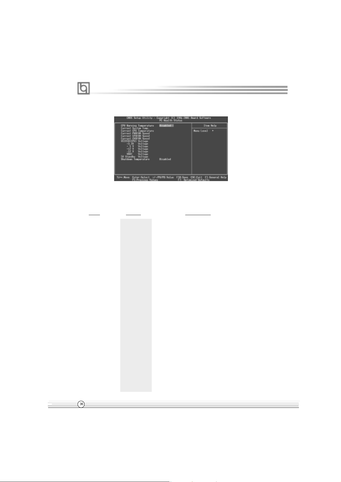
PC Health Status
Figure-9 PC Health Status Menu
The following indicates the options for each item and describes their meaning.
Item Option Description
# CPU Warning
Temperature
500C/1220F
530C/1270F
560C/1330F
600C/1400F
630C/1450F
660C/1510F
700C/1580F
750C/1670F
800C/1760F
850C/1850F
900C/1940F
950C/2050F
Disabled
An alarm will beep when the CPU
temperature reaches the previous setting,
500C/1220F, 530C/1270F, 560C/1330F,
600C/1400F, 630C/1450F, 660C/1510F, 700C/1580F.
750C/1670F, 800C/1760F, 850C/1850F, 900C/1940F,
950C/2050F.
No alarm beep.
# Current System The temperature inside the chassis.
Temp.
# Current CPU The temperature of CPU.
Temperature
# Current PWRFAN RPM (Revolution Per Minute) Speed of fan which
Speed is connected to the fan header, CPUFAN, CHSFAN
Current CPUFAN or PWRFAN. Fan speed value is based on an
Speed assumption that tachometer signal is two pulses
Current CHSFAN per revolution. In other cases, you should regard
Speed it relatively.
Manual for PlatiniX 2 series
Page 43

Chapter 3
# VCCVID(CPU) Display current voltage value including all
Voltage, significant voltages of the mainboard.
+3.3V +3.3V, +5V, +12V, -12V are voltages from the
+5 V power supply.
+12 V
-12 V VCCVID (CPU) Voltage is the CPU core
VBAT Voltage voltage from the on board switching Power
5V Standby Voltage Supply. The VBAT Voltage is the voltage of
battery.
#"Shutdown """"""
Temperature
650C/1490F
700C/1580F
750C/1670F
600C/1400F
Disabled
The system will shut down automatically under
the ACPI OS when the CPU temperature
reaches the previous setting.
The system remains on regardless of how
much the CPU temperature is.
Manual for PlatiniX 2 series
Page 44

BIOS Description
Password Setting
When this function is selected, the following message appears at the center of the screen
to assist you in creating a password.
ENTER PASSWORD
Type the password, up to eight characters, and press <Enter>. The password typed now
will clear any previously entered password from CMOS memory. You will be asked to
confirm the password. Type the password again and press <Enter>. You may also press
<Esc> to abort the selection.
To disable password, just press <Enter> when you are prompted to enter password. A
message will confirm the password being disabled. Once the password is disabled, the
system will boot and you can enter BIOS Setup freely.
PASSWORD DISABLED
If you have selected “System” in “Security Option” of “BIOS Features Setup” menu, you will
be prompted for the password every time the system reboots or any time you try to enter
BIOS Setup.
If you have selected “Setup” at “Security Option” from “BIOS Features Setup” menu, you will be
prompted for the password only when you enter BIOS Setup.
Supervisor Password has higher priority than User Password. You can use Supervisor
Password when booting the system or entering BIOS Setup to modify all settings. Also you
can use User Password when booting the system or entering BIOS Setup but can not
modify any setting if Supervisor Password is enabled.
Boot with BIOS defaults
If you have made all the changes to CMOS values and the system can not boot with the
CMOS values selected in setup, clear CMOS after power-down, then power on again.
System will boot with BIOS default settings.
Manual for PlatiniX 2 series
Page 45

Appendix
Appendix
QDI Utility CD
A QDI Utility CD is supplied with this mainboard, the contents contained in it are showed
as below:
1. Driver Install
Using this choice, you can install all the drivers for your mainboard easily. You should
install the drivers in order, and you need to restart your computer until all the drivers are
installed.
A. Chipset software B. Network Driver(optional)
C. Audio Driver(optional) D. DirectX
2. Accessory
A: QDI ManageEasy B: QDI StepEasy(optional)
C: Norton AntiVirus
3. Browse CD
You could read all the contents contained in this CD, including Utility and Documents.
The files included in Utility are:
A. Awdflash.exe B. Cblogo.exe
C. Lf.exe
The files included in Documents are:
A. Adobe Acrobat Reader V3.0 - Ar32e301.exe
B. RecoveryEasy-FR.doc, PlatiniX 2 FR.doc, Handbuch-manageEasy,etc.
Manual for PlatiniX 2 series
Page 46

Appendix
QDI ManageEasy V2.0
It is well known that guaranteeing the computer’s security and reliability is essential. Especially today, effectively managing and monitoring the computer’s hardware is even more
important; because processing and exchanging critical data through computer and network
are happening everyday .
Moving with the computer’s development, the system of the computer will become more and
more complex; at the same time, the control computer’s hardware will be strengthened.
T oday , it is possible to monitor and manage your complex hardware from Windows 9X and
Windows NT . QDI ManageEasy is a system tool, a bridge between the complex hardware
and OS, used to access hardware status and to execute control functions. It supports
stronger functions for Windows 9X and Windows NT. These functions enables you to view
more than one hundred of the basic information about the system and monitor some key
reference data concerning computer health in real time. QDI ManageEasy also helps you to
use remote access and control computers in your local area network. With QDI ManageEasy , you can improve your management level.
Installation of QDI ManageEasy V2.0
Run Setup.exe from the utility CD directory \QME2 to install the QDI ManageEasy V2.0. The
QDI ManageEasy Setup Wizard will guide you through the installation process. For detailed
information on how to use QDI ManageEasy V2.0, please refer to the QDI ManageEasy V2.0
online help.
BIOS-ProtectEasy
The BIOS of the mainboard is contained inside the Flash ROM. Severe viruses such as CIH
virus are so dangerous that it may overwrite the BIOS of the mainboard. If the BIOS has
been damaged, the system will be unable to boot. We provide the following solution which
protects the system BIOS from being attacked by such viruses.
There are two choices which implements this function.
1. Set the jumper (JAV) as closed, the BIOS can not be overwritten.
2. Set the jumper (JAV) as opened, meanwhile set “Flash Write Protect” as Enabled in
AWARD BIOS CMOS Setup. In this way, the BIOS can not be overwritten, but the DMI
information can be updated.
Norton AntiVirus
When you install Norton AntiVirus and accept options, your computer is safe. Norton
AntiVirus automatically checks boot records for viruses at system startup, checks programs for viruses at the time you use them, scans all local hard drives for viruses once per
week, and monitors your computer for any activity that might indicate the work of a virus in
action. It also scans files you download from the internet and checks floppy disks for boot
viruses when you use them. The list below shows the most important tasks Norton AntiVirus
helps you perform: scan for viruses on your computer; remove viruses from your computer; update your virus protection with LiveUpdate; quarantine an infected file.
You can go to the Symantec W eb site to view an online tutorial:
http://www.symantec.com/techsupp/tutorial/nav2001
Manual for PlatiniX 2 series
Page 47

Appendix
LogoEasy
When you power on or reset your system, the picture shown below will be displayed on
the screen.
Y ou can use “CBLOGO.EXE” ( included in the QDI Driver CD ) to replace it by any other logo
which you prefer.
Please follow the steps to use CBLOGO.EXE Utility:
1. Copy “CBLOGO.EXE”and “AWDFLASH.EXE” from the directory \Utility located on
QDI Driver CD to your hard disk.
2. Get the BIOS file from “AWDFLASH.EXE” or Download the BIOS file from the Website
(http://www.qdigrp.com) and copy the BIOS file(xxxxxx.bin) to your hard disk.
3. Boot the system into DOS environment, Put your favor picture into BIOS file by
“CBLOGO.EXE” command. F or example: CBLOGO.EXE xxxxxx.bin myphoto.bmp
4. Flash the BIOS to motherboard by “AWDFLASH.EXE”. For example: AWDFLASH
xxxxxx.bin
Reboot the system, you can see the new picture displayed on the screen. If you require
more parameters information concerning “CBLOGO.EXE”, please refer to the online help. If
you don’t prefer the logo displayed on the screen during bootup, set the “Show Bootup
Logo” option as Disabled in the “ADV ANCED BIOS FEA TURES ” section of the BIOS.
* We reserve the right of modifying the default full-logo of QDI without further
notification.
Manual for PlatiniX 2 series
Page 48

Appendix
SpeedEasy Quick Setup
Procedures :
1. Correctly insert the CPU.
2. Plug in other configurations and restore the system.
3. Switch on power to the system and press the <Del> key to enter BIOS Setup.
4. Enter “CPU SpeedEasy Setup” menu to set up the CPU speed.
5. Save and exit BIOS Setup, your system will now boot successfully.
Manual for PlatiniX 2 series
Page 49

Appendix
CPU SpeedEasy Setup Menu
Select <CPU SpeedEasy Setup> item from the main menu and enter the sub-menu:
CPU SpeedEasy Setup Menu
BIOS provides you with a set of basic values for your processor selection instead of the
jumper settings. The processor speed can be manually selected on the “CPU SpeedEasy
SETUP” menu screen.
Warning:
Do not set CPU frequency higher than its working frequency . If you do, we will
not be responsible for any damages caused.
Manual for PlatiniX 2 series
A.5
Page 50

Appendix
QDI BootEasy
BootEasy is a new member of legend QDI Easy series, which is the latest innovation comes
from legend QDI.
BootEasy Setup Menu
BootEasy technology enormously shorten the long BOOT process time of computers. Reducing the wait time every user has to suffer when starting their computer. BIOS without
BootEasy has to perform many routines every time when the system starts, such as
checking system core of the computer and initializing system peripherals. Now with the
BootEasy, BIOS will not run these repetitive Processes any longer , PC can boot-up without
any redundant waiting for the displaying of starting OS. BootEasy is quite easy to use ,
choose the right option in CMOS SETUP , ( refer to Advanced BIOS Features) it can be easily
booted quickly. BootEasy save all the information when PC first normally boot-up, and it
restores all the parameters for the system and thus let the PC boot freely and rapidly.
Note:
1. Under the following conditions, PC will boot-up in normal way.
(1) PC boot-up for the first times after set option as Enabled.
(2) the system information saved by BIOS was damaged.
(3) PC fail to boot-up continually over three times.
Note: Please make sure the jumper “JAV” is set as OPEN under these conditions.
2. Don’t power off or reset system while BootEasy initializing.
3. Set “QDI BootEasy Feature” as “Disabled” before you replace system equipment.
Set “QDI BootEasy Feature” as “Enabled” after you accomplished replacing.
Manual for PlatiniX 2 series
Page 51

Appendix
QDI BootEasy
Boot Easy e il nuovo software membro della famiglia legend QDI Easy, quale innovazione da
LEGEND- QDI.
BootEasy Setup Menu
La tecnologia Boot Easy abbrevia gli enormi tempi del computer in fase di BOOT .
Riduce le attese d’ogni utente che accede al suo computer. Il BIOS senza Boot Easy
deve eseguire molte routines ogni qualvolta il sistema parte, come controllo della sezione
centrale del computer oltre che inizializare le varie periferiche esterne.
Ora con Boot Easy, il BIOS non eseguirà questi processi ripetitivi cosi lunghi , il Pc potrà
partire senza attese ridondanti prima della presentazione del logo del sistema operativo.
Boot Easy e’ facile da usare, basta scegliere la giusta opzione nel BIOS setup,
( riferito al Advanced BIOS Features ) ed il computer potrà velocemente ripartire.
Boot Easy salva tutte le informazioni al primo avvio normale, tutti i parametri saranno restituiti
ai BOOT successivi
Nota:
1 Il Pc partira’ normalmente se saranno rispettate le seguenti condizioni
(1) Il Pc fa’ il primo BOOT con l’opzione Enable
(2) Le informazioni su i parametri salvati dal BIOS non erano DANNEGIATE
(3)Il PC fallisce l’avvio piu’ di tre volte
Non spegnere o resetta il PC durante l’avvio di BOOT EASY
Disabilita il “QDI BootEasy Feature” prima di sostituire le periferiche ad esso collegate ( HDD,
CD-ROM, ecc.) solo dopo riabilita il “QDI BootEasy Feature”.
Manual for PlatiniX 2 series
Page 52

Appendix
QDI BootEasy
BootEasy es el nuevo miembro de la familia de “Easies” de Legend QDI , que se acaba de
incorporar a los últimos modelos de placas base.
Menu de configuración de BootEasy
La tecnología BootEasy disminuye enormemente el tiempo dedicado al proceso de arranque
del ordenador, reduciendo considerablemente el tiempo de espera que tiene que sufrir el
usuario al arrancar su PC. Las BIOS normales, sin BootEasy, deben realizar multitud de
rutinas repetitivas cada vez que el sistema se arranca, como verificar el “core” del sistema
e inicializar periféricos. Ahora, con BootEasy, su BIOS no realizará estas tareas repetitivas
nunca más, su PC podrá arrancar sin ninguna necesidad de repetir estas tareas antes de
mostrar la pantalla de arranque de su sistema operativo. BootEasy es muy simple de utilizar,
basta con escoger la opción correcta en CMOS SETUP , (refiérase al apartado Advanced
BIOS Features); Así, conseguirá arrancar su sistema rápidamente. BootEasy guardará
toda la información durante el primer arranque correcto, y, la próxima vez que arranque,
restaurará esta información para permitir al sistema un arranque rápido y fiable.
Nota:
1. Bajo estas circunstancias, el PC arrancará en modo normal:
(1) La primera vez que arranque su PC después de haber activado la opción BootEasy
en BIOS (“Enabled”).
(2) La información guardada en BIOS es incorrecta.
(3) El arranque de su PC falla por tres veces consecutivas.
2. No apague su ordenador mientras se inicia BootEasy.
3. Desactive “QDI BootEasy Feature” seleccionándolo como “Disabled” antes de
cambiar algún componente de su PC. Puede restaurar la opción “QDI BootEasy
Feature” como “Enabled” al terminar la instalación de nuevos componentes.
Manual for PlatiniX 2 series
Page 53

Appendix
QDI BootEasy
BootEasy ist eine Neuentwicklung von Legend QDI, die neue Innovation der QDI Easy –
Technologien.
BootEasy Setup Menu
Mit der BootEasy- T echnologie Technik wird der Bootvorgang nur noch vier bis fünf
Sekunden in Anspruch nehmen, bis das Betriebssystem geladen wird. Der Grund für die
lange Warterei liegt in den Routine-Abfragen, die das BIOS bei jedem Start abarbeitet. So
wird beispielsweise jedes Mal die T aktfrequenz des Prozessors geprüft oder
angeschlossene Geräte aktiviert.
Die BootEasy-T echnik prüft diese Punkte nur beim erstmaligen Start des Rechners und
speichert die Ergebnisse in einem Flash ROM. Beim nächsten Start ruft das System
lediglich diese Informationen aus dem Speicher ab und kann so innerhalb von wenigen
Sekunden den Boot-Prozess abschließen.
Bei Änderungen am System, beispielsweise nach dem Einbau eines neuen Prozessors,
muss deshalb zuvor die BootEasy-Funktion deaktiviert werden, beim nächsten Start
werden die neuen Informationen dann erneut abgespeichert.
Falls Fehler im Flash ROM den Bootvorgang behindern, versucht das System drei Mal den
Rechner hochzufahren, bei Misserfolg schaltet es auf die althergebrachte Art zu booten
um, das heißt, es dauert wieder ebenso lang wie früher. Anschließend kann die
BootEasy – Technik wieder aktiviert werden.
Manual for PlatiniX 2 series
Page 54

8
8
8
8
8
8
Appendix
23456789012345678901234567890121234567
23456789012345678901234567890121234567
23456789012345678901234567890121234567
23456789012345678901234567890121234567
RecoveryEasyRecoveryEasy
RecoveryEasy
RecoveryEasyRecoveryEasy
RecoveryEasyRecoveryEasy
RecoveryEasyRecoveryEasy
RecoveryEasy
RecoveryEasy
RecoveryEasyRecoveryEasy
RecoveryEasyRecoveryEasy
23456789012345678901234567890121234567
23456789012345678901234567890121234567
Introduction:
RecoveryEasyTM, the latest QDI innovation, is able to protect the system from being
destroyed, by creating a so-called “mirror partition” for a current hard disk partition
and backuping all the data to the mirror area. This ideal utility provides disk partition,
disk data backup/recovery, CMOS settings backup/recovery and multi-boot functions.
RecoveryEasy is also able to prevent the system from being attacked by different
kinds of boot virus or other severe virus such as CIH. In case the system is ruined
either by mistake or virus, the system can be recovered from the mirror partition. It
applies the build-in BIOS technology that does not occupy either the hard disk space
or the system memory . It ’s the best choice for both corporations and PC users.
Operation Process:
There are two hotkeys – Ctrl+Bksp and F12 for RecoveryEasy to enter “Partition” and
“Recovery” user interfaces accordingly during BIOS booting up. If two or more hard
disks are installed, use F5 key to choose the hard disk.
1. Partition Interface (see figure-1)
Users can create and delete partitions/mirror partitions, activate partitions, and uninstall
RecoveryEasy in Partition User Interface.
figure-1 Partition Interface
1.0 Install RecoveryEasy for the first time
a. The utility checks the previous disk partition at first, and displays the status of
the first four partitions. If there are more than four disk partitions, users will be
asked to delete the redundant disk partitions, since only four partitions that can
be activated are allowed to exist. However, if there’re only four or fewer partitions, users can follow the system prompt and choose to install RecoveryEasy
based on the previous disk partitions. In this way, the original extension partitions will be changed to normal ones, and probably the sequence of the partitions will be changed also, but the contents contained in each partition will
remain the same.
Manual for PlatiniX 2 series
Page 55

Appendix
b. If choosing to install RecoveryEasy on an absolutely clear disk, the utility will
delete all the previous partitions.
c. The password is set as default setting “qdiqdi” after installing RecoveryEasy .
1.1 CREA TE P AR
Function : Creates a new partition.
Limitation: When no disk space remains or 4 partitions already exist, this button is
disabled.
Steps : After pressing the “CREA TE P AR” button.
a. The system will prompt whether users want to create a mirror partition for it or
not.
b. If answering “Y”, input the new partition size in Megabyte. Notice that the
maximum partition size that can be assigned is half of the left disk space, which
is also displayed in the status line. Another half is for the mirror partition. If
answering “N”, the whole disk space left can be assigned. See figure-2.
figure-2 Create Partition
Note:
a. The system will prompt “Insert system floppy, then reset” when the first
partition on the first hard disk is created.
b. After using DOS6.xx boot disk to format C partition, the system should be reset in
order to access the partition.
c. In Windows system 1,048,576 bytes equal 1 Megabyte, while in RecoveryEasy
1,000,000 bytes equal 1 Megabyte, therefore a smaller size will be displayed in
Windows system compared with the size displayed in RecoveryEasy .
1.2 DELETE P AR
Function : Deletes the last partition and its mirror partition.
Limitation: When no partition exists, this button is disabled.
Steps : After choosing this function, only the final partition can be deleted in
order to keep the continuous disk space. If the warning message is
confirmed, the partition will be deleted. By pressing “N” or “ESC” key,
the system quits.
Manual for PlatiniX 2 series
Page 56

Appendix
1.3 ACTIVE P AR
Function : Implements multi-boot function by activating one of the partitions.
Limitation: When no partition exists, this button is disabled.
Steps : If there’re two or more partitions, choose one of them by pressing F5
key.
Note : After setting active partition, a letter “A” will be shown in front of this
partition.
1.4 CREAT E MIR
Function : Adds mirror partition for the disk partition that has no mirror .
Limitation: This function should be performed by order, for example, from partition
1 to 4. If no disk space remains or the last partition has its mirror
partition already , this button is disabled.
Steps : After pressing the “CREA TE MIR” button, use F5 key to choose the
partition to create mirror. The partition of which the size is bigger than
the left disk space will be ignored.
1.5 DELETE MIR
Function : Deletes the mirror partition.
Limitation: If there is no mirror partition, this button is disabled. This function
should be performed in reverse order, for example, from partition 4 to 1.
Steps : After pressing the “DELETE MIR” button, only the final mirror partition
can be deleted in order to keep the continuous disk space. If the
warning message is confirmed, the mirror partition will be deleted. By
pressing “N” or “ESC” key , the system quits.
1.6 UNINST SFW
Function : Uninstall RecoveryEasy.
Limitation: None.
Steps : After pressing the “UNINST SFW” button and the warning message is
confirmed, RecoveryEasy will be uninstalled. By answering “N”, the
system quits.
Note : After RecoveryEasy is uninstalled, all the mirror areas have been
disconnected with the relate partitions. If no partition is deleted or
changed in size, or no other partition is created, users have chance to
“Recover existing RecoveryEasy settings” when next time entering
RecoveryEasy partition interface, meanwhile the password will be set
as default setting “qdiqdi”.
1.7 OTHERS
F12 : Switches to Recovery User Interface.
ESC : Exits from the Partition User Interface. If users made some mistakes, for
example, wrongly delete a partition, do not press the “ESC” key, press the
reset button on your system at once, in this way users can save their system.
Manual for PlatiniX 2 series
Page 57

Appendix
F5:
a. When two or more than two hard disks are installed on the system, use F5
key to choose the hard disk. Every time users use F5 key to switch the hard
disk, the operation result for the previous hard disk is saved. When processing
a certain hard disk, F5 key can be used to choose the partition.
b. In addition, when two or more than two hard disks are installed, the sign of
partitions will be changed from C, D, E, F to 1, 2, 3, 4 accordingly.
2. Recovery Interface (see figure-3)
Users can backup the partition to its mirror area, and recover the partition from its
mirror area from Recovery User Interface. This interface also provides users with
CMOS settings backup or recovery , and changing password functions.
figure-3 Recovery User Interface
2.1 BACKUP PAR
Function : Backups the content of the partition to its mirror area.
Limitation: If no mirror partition exists, this button is disabled.
Steps:
a. Use F5 key to choose the partition with mirror area existed.
b. If the partition chosen has been backuped before, a warning message will be
shown, and the time when last backup was done will be displayed in the status line.
After confirming the warning message, the system performs the backup. By pressing “N” or “ESC” key , the system quits.
2.2 RE-CVR P AR
Function : Recovers the content from the mirror area to the relate partition.
Limitation: If users didn’t backup any partitions before, this button is disabled.
Steps:
a. Use F5 key to choose the backuped partition.
b. The time when the latest backup was done will be displayed in the status line.
After confirming the warning message, the system performs the content
recovery. By pressing “N” or “ESC” key , the system quits.
Manual for PlatiniX 2 series
Page 58

Appendix
Note:
a. During the process of partition backup or recovery , a guage will be shown as
below, the backup or recovery speed is about 4-5Mbyte/s. See figure-4.
figure-4 Backup Partition
b. If a disk I/O error occurs during the process of partition backup or recovery, this
means there’s physical damage on the hard disk, however users can ignore it
and continue the process.
2.3 ATTRIB PAR
Function : Allows users to modify the properties of the partition (eg. FA T16 ->
FAT32) after entering OS.
Limitation: None.
Steps : After pressing this button, turn on/off the switch.
Note:
a. The switch resets to the default setting “disable” every time the system reboots.
b. In order to implement this function, users need to enable the switch wheninstall-
ing the OS or modifying the partition properties. Please note: Do not create or delete
partitions or change the partition size when modifying the partition properties.
2.4 BACKUP CMS
Function : Backups all CMOS settings.
Limitation: None.
Steps : After choosing this function, the current CMOS settings will be saved.
2.5 RE-CVR CMS
Function : Recovers all CMOS settings.
Limitation: None.
Steps : After choosing this function, the latest backup of the CMOS settings
will be recovered. The system needs reboot in order to validate the
new CMOS settings.
Note : If users have never backuped the CMOS settings, a wrong message
will be shown after choosing this function.
Manual for PlatiniX 2 series
Page 59

Appendix
2.6 CHANGE PWD
Function : Changes the password to enter RecoveryEasy Partition or Recovery
User Interface.
Limitation: None.
Steps : Follow the system prompt, input the password no more than 6
characters twice. To delete the password, follow the system prompt
and press the “Enter” key twice.
Note:
a. The password should be no more than 6 characters, only digital and alphabetic
letters are valid.
b. Once the password is enabled, users will be asked to input the password every
time they try to enter the RecoveryEasy user interfaces, and up to 3 times try is
permitted.
2.7 Others
Ctrl+Bksp : Switches to Partition User Interface.
ESC : Exits from the Partition User Interface.
F5 : When two or more than two hard disks are installed on the system,
use F5 key to choose the hard disk. When processing a certain hard
disk, F5 key can be used to choose the partition.
FAQ:
1. What does RecoveryEasy do?
RecoveryEasy creates a so-called “mirror partition” with same size for the
hard disk partition on the same hard disk, and then completely backups all the
data sector by sector to the mirror area. This mirror partition is reserved to
OS. When the OS ruins either by mistakes or virus, users can recover the
partition from its mirror .
2. Does RecoveryEasy occupy the system resources?
Although some hard disk data protection applications can automatically
protect the disk data in runtime, it lowers the system performance. Unlike
theseapplications, RecoveryEasy need users to backup or restore data
manually when needed, but it DOES NOT lower the system performance
when the system is running. It does not occupy either hard disk space or
system memory, additional floppy disk or ISA/PCI cards are unnecessary.
3. RecoveryEasy utilizes Build-in BIOS skill, what is build-in BIOS?
RecoveryEasy build-in BIOS means all functions of RecoveryEasy including
creating partition, backuping and restoring partition are built in BIOS. Users just
need to down load the latest BIOS from our Website (http://www .qdigrp.com)
when wanting to upgrade (It’s free!).
Manual for PlatiniX 2 series
Page 60

Appendix
4. Are there any hard disk limitations of RecoveryEasy?
RecoveryEasy supports all kinds of current IDE hard disks and has no limitation on the hard disk capacity. RecoveryEasy can not provide its function for
some special hard disk types such as SCSI, but it will not affect their usage.
5. Are there any OS limitations of RecoveryEasy?
RecoveryEasy supports current operating systems such as DOS, Windows
95/98. However in Windows NT , Windows 2000, Unix and OS2 systems,
users should notice that the disk tools bundled in the OS could change the
mirror partition. On the other hand, since users can create partition with
RecoveryEasy, it is unnecessary to use other disk tools.
6. Why does the remainder size plus partitions size not match the
total size shown in RecoveryEasy sometimes?
When the location of partitions is not continuous, the above problem exists.
7. Are there any other disk partition tools that can modify the partition
table made by RecoveryEasy?
RecoveryEasy provides a write-protect function, so the disk tools such as
Fdisk, Partition Magic, BootMenu, SmartDisk and BootStar can not modify the
partition table created by RecoveryEasy. Some of the applications even
terminate during operation. However the disk tools bundled in the OS such as
Windows NT , Windows 2000, Unix and OS2 could change the mirror partition.
8. Why does it happen that a prompt “
installation can not continue”
pops up when installing Windows98 or a yellow exclamation mark
shown beside IDE device in system properties?
During Windows 98 installation, the installation program will write to MBR
(Master Boot Record) which is protected by RecoveryEasy, therefore the
installation will be terminated. T o avoid this problem, a “A TTRIB P AR” button
is provided in Recovery User Interface. Enable this switch before installing
Windows 98, then the installation will be successfully completed. In order to
remove the yellow question mark before IDE devices in Device Manager,
enable this switch once more after system reboot.
9. Why does the converting of FAT16->FAT32 in PQ Magic go wrong?
MBR will be accessed when converting FAT16 to FAT32 with PQ Magic,
which is protected by RecoveryEasy, therefore the conversion will beinvalidate. Enabling the “ ATTRIB PAR” switch from Recovery User Interface
before converting can avoid this problem. It’s the same situation as “FAT32
Converter” provided in Windows98.
10. What if partitions be wrongly deleted in RecoveryEasy?
If users delete a partition in RecoveryEasy by mistake, they can save it by
pressing the Reset button on their system at once. Do not press the “ESC”
Manual for PlatiniX 2 series
Page 61

Appendix
key to quit RecoveryEasy , this will save the change. Do not try to create the
partition again, since creating partition will clear all the content of the partition.
11. What is multi-boot?
RecoveryEasy can implement the multi-boot function by activating different
partition. For example on the hard disk, partition C contains DOS, partition D
contains Windows 95 version, partition E contains Windows 98 version, when
activating partition C in RecoveryEasy , the system enters DOS, when activating
partition E, the system enters Windows 98 version. At the same time, the
sequence of the partitions is adjusted accordingly, partition E becomes C:,
partition C becomes D: and partition D becomes E:. This function is the same as
that of fdisk.exe, but the system needs reboot in order to make the change
validate for fdisk.exe.
12. What if computer accidentally power off when backuping (recovering)?
The partition should be completely backuped or recovered. If the computer
accidentally powers off, the partition should be backuped or recovered once
again.
13. What if users lose the password?
To make sure the security , the password is saved in the hard disk. It’s very
important for users to remember the password. If forgetting the
password, contact us, clearing CMOS is useless.
14. Does RecoveryEasy protect hard disk against CIH?
RecoveryEasy can strongly protect the hard disk from boot-virus, as well as the
attack of CIH. If the system is attacked by CIH, RecoveryEasy will automatically
recover the MBR and each partition boot record before system boots up, and try
to recover the F A T. In this way the system can basically boot up, then users can
use some anti-virus application to kill the virus. However this depends on how
th
CIH virus affects the system. CIH normally outbreaks on 26
every month, if the
system cannot boot up that day, power off the computer instantly , and use the
second safe way to recover the system, that is, recover the partition from its
mirror area from Recovery User Interface. Remember to create a mirror partition
and backup before virus attacks the system.
Manual for PlatiniX 2 series
Page 62

Appendix
QDI StepEasy(optional)
As one of the Legend QDI’s innovations, StepEasy is a powerful and efficient Easy Technology for PC DIY fans. It provides a friendly interface for you that you can adjust the CPU
frequency conveniently and directly. It is so powerful that you can change the CPU frequency
just in a few seconds under the operating system and have no need to reset the PC or change
the jumpers. In addition, StepEasy can decrease the risk of changing the CPU frequency to
minimum. As long as you conform to the steps of tuning the CPU frequency , there is almost no
risk to adjust the frequency.
10MHz decrease
1MHz decrease
button to run at the
select frequency
button to run at the
default frequency
10MHz increase
1MHz increase
Installation
Y ou can install the QDI StepEasy by the following two means:
1. Run CD, select the installation of QDI StepEasy, then, act step by step according to the
interface prompt.
2. Browse CD and run the setup.exe in the relative directory .
Instructions
Because there exist some risks for the CPU or the motherboard when you change the CPU
frequency , please read the following and refer to the figure above carefully before tuning the
CPU frequency .
A.18
Manual for PlatiniX 2 series
Page 63

Appendix
The select CPU frequency is shown in the LED window with three colors: green digits indicate
the frequency is entirely safe, yellow digits indicate the frequency is relatively safe, and red
flashing digits indicate the frequency is somehow dangerous that may lead the system down.
We recommend you not to select the Red Flashing frequency to run.
To avoid accident, we recommend you to save your program before run StepEasy.
1. Y ou can click on the 1MHz increase (decrease) or 10MHz increase (decrease) button to set
your wanted frequency , then click on the “GO” button to run at the select frequency.
2. Also, you can drag the slider to the wanted frequency , then click on the “GO” button to run
at the select frequency .
3. You can click on the “Default” button, then click on the “GO” button to run at the default
frequency.
4. StepEasy enables you to save the successful CPU tune frequency for next use. If you want
to save the current frequency , click on the “Save” button to realize it.
5. When click on the “Load” button, the saved CPU frequency is obtained immediately .
6. When click on the “Min” button, the utility will minimize to an icon in the right-bottom task tray .
Whenever click on the QSE(QDI StepEasy ) icon in the task tray , the utility will be activated in
the current window.
Note:
1. QDI StepEasy can only support the QDI motherboard with the clock chip that supports
StepEasy.
2. The performance of StepEasy depends on the CPU, SDRAM, peripheral equipments and the
software running.
3. There exist some risks to change the CPU frequency for the CPU or motherboard. StepEasy
can decrease the risks to minimum. But Legend QDI will not be responsible for any damages
caused.
4. In order to reduce the risks, it is recommended to increase/decrease the CPU frequency by 1MHz.
Manual for PlatiniX 2 series
A.19
Page 64

Appendix
Installation de la carte mère PlatiniX 2 :
1. Assurez-vous que votre ensemble est complet: carte mère, câbles IDE et FLOPPY,
notice d’utilisation et CD-ROM d’installation.
2. Vérifiez que l’alimentation est débranchée et reliez-vous à la terre par une courroie
à votre poignet. A défaut, maintenez le contact de vos deux mains avec un objet luimême relié à la terre, ou une partie en métal de votre système.
3. Fixez la carte mère dans le boîtier grâce aux vis fournies avec celui-ci.
4. Si votre carte mère est munie de cavaliers, placez les en fonction des options que
vous souhaitez utiliser: réglage de la fréquence du processeur si votre carte n’est
pas SpeedEasy, fonction allumage par saisie du mot de passe…(voir le manuel,
rubrique «configuration des cavaliers» pages 13 à 16)
5. Insérez le processeur dans son logement avec son ventilateur que vous
brancherez au connecteur «CPUFAN».
6. Insérez la/les barrette(s) mémoire dans les slots RIMM.
7. Installez vos éventuelles cartes PCI et AMR dans les slots prévus à cet effet (voir
page centrale du manuel).
8. Branchez vos périphériques IDE et FLOPPY sur les connecteurs prévus à cet effet
grâce aux nappes fournies avec la carte. Vérifiez que le sens de branchement est
correct (liseré rouge du câble sur la broche 1 du connecteur).
9. Reliez les câbles du boîtier aux connecteurs prévus à cet effet (Connecteur
d’alimentation, LED de marche/arrêt, disque dur , haut-parleur…voir manuel pages 9
à 12). Refermez le boîtier.
10. Branchez les périphériques externes sur les sorties du fond de panier: clavier,
souris PS/2, périphériques USB, moniteur, imprimante…(voir manuel pages 7-8)
11. Lorsque tous les éléments du système sont installés physiquement, rebranchez
l’unité centrale.
Installation du système.
1. Démarrez votre système en pressant le bouton «POWER».
2. Pressez la touche «Suppr» pour entrer dans le setup du BIOS.
3. Dans le menu «SpeedEasy CPU Setup», réglez la vitesse de votre processeur
(A TTENTION: il est recommandé de ne pas sélectionner une fréquence supérieure à
celle de votre processeur, nous déclinons toute responsabilité pour les dommages
qui en résulteraient)
4. Effectuez les autres réglages du BIOS selon votre configuration (nous vous
conseillons fortement de maintenir les réglages par défaut afin d’éviter toute
manipulation hasardeuse pouvant résulter en un dysfonctionnement). Pour plus
d’informations sur les fonctions du BIOS, vous pouvez consulter la version
française du manuel sur le CD-ROM.
A.20
Manual for PlatiniX 2 series
Page 65

Appendix
5. Pressez la touche F10 ou choisissez «Save and exit» pour enregistrer vos
paramètres et relancer la machine.
6. Installez votre système d’exploitation
7. Après installation, assurez-vous qu’il ne subsiste aucun conflit ou périphérique
inconnu dans votre système.
8. Installation des pilotes:
1. Driver Install
Avec cette option, vous pouvez installer les pilotes de votre carte mère facilement.
Vous devez installer les pilotes dans l’ordre et redémarrer votre ordinateur lorsque
tous les pilotes sont installés.
A. Pilotes du Chipset
B. Pilote audio
C . DirectX
2. QDI ManageEasy:
Lancez le setup.exe du répertoire \QME pour installer le ManageEasy. Pour des
informations détaillées sur le ManageEasy, référez-vous au manuel ManageEasy du
répertoire \Doc.
N’oubliez pas de redémarrer votre système pour que les changements soient pris
en compte.
3. RecoveryEasy
RecoveryEasy permet de protéger le système des destructions en créant une «partition
miroir» de la partition courante du disque dur et en sauvegardant toutes les données dans
ce «miroir».
Cette utilitaire fournit partition du disque, récupération/sauvegarde des données,
récupération/sauvegarde des réglages du CMOS et fonctions multi-boot.
RecoveryEasy permet également la protection du système contre les divers types de virus
de boot tels que CIH. Dans le cas où le système est perdu soit par erreur , soit à cause d’un
virus, il peut être récupéré depuis la partition miroir. Cette innovation utilise la technologie du
Bios intégré qui n’occupe ni l’espace disque, ni la mémoire du système. C’est la solution
idéale pour l’utilisateur .
Il faut presser les touches Ctrl + Bksp et F12 pour entrer dans les interfaces «Recovery»
et «Partition» durant le démarrage du Bios.
ATTENTION : lisez attentivement le manuel du RecoveryEasy traduit sur le CD-ROM QDI
avant d’installer cette fonction.
Très important : n’oubliez pas votre mot de passe, faute de quoi vous
n’auriez plus accès au RecoveryEasy, même après avoir effectué un Clear
CMOS.
Manual for PlatiniX 2 series
A.21
Page 66

Appendix
QDI BootEasy
BootEasy est la dernière née des technologies Legend QDI.
Voir figure page 14 du manuel en anglais.
BootEasy permet au PC de démarrer plus rapidement lorsqu’on allume, reset ou relance le
PC.
Avec le BootEasy , le PC peut démarrer en un instant, sans attente redondante pour
afficher le démarrage du système d’exploitation.
BootEasy est facile à utiliser, il suf fit de choisir l’option correcte dans le menu «Advanced
Bios Features Setup».
BootEasy sauvegarde toutes les informations lorsque le PC boote et restaure les
paramètres pour le système, permettant ainsi au PC de démarrer rapidement.
Note:
1. Le PC démarre de manière classique dans les cas suivants:
- Premier démarrage après activation de l’option
BootEasy
- Informations sauvegardées endommagées
- Echec au démarrage du PC à 3 reprises
2. N’arrêtez pas ou ne redémarrez pas le système lorsque BootEasy s’initialise
3. Placez «QDI BootEasy Feature» sur «Disabled» avant de changer un composant du
système
Placez «QDI BootEasy Feature» sur «Enabled» après avoir effectué le changement.
Le menu SpeedEasy
I. Insérez le processeur correctement.
I I . Connectez les autres éléments du système (voir Installation).
III. Au démarrage du système, pressez la touche <Suppr> pour entrer dans
le Bios
IV . Entrez dans le menu «CPU SpeedEasy setup»
Note: si vous ne déterminez pas la vitesse de votre unité centrale, votre
système fonctionnera par défaut
V. Sauvegardez et quittez le Bios.
A.22
Manual for PlatiniX 2 series
Page 67

Appendix
CMOS Setup Utility – Copyright© 1984-2000 Award Software
SpeedEasy CPU Setup
CPU Host/PCI Clock: 66/33MHz Item Help
Close empty DIMM/PCI Clk: Enabled
Spread Spectrum Disabled Menu Level >
Prévenir :
Le menu SpeedEasy vous fournit un ensemble de valeurs. Vous pouvez sélectionner
manuellement la vitesse de CPU dans ce menu soit en mode «SpeedEasy» soit en
mode «Jumper Emulation» (voir manuel).
ATTENTION: Ne pas sélectionner une fréquence de fonctionnement du CPU
supérieure à celle indiquée par le constructeur. Nous déclinons toute
responsabilité pour tout dégât qui en résulterait.
Manual for PlatiniX 2 series
A.23
Page 68

PlatiniX 4X
Form Factor: ATX
CPU: Socket-423
Chipset: Intel 850
FSB: 400MHz
Memory: 4 PC800/PC600 RDRAM
IDE: ATA 100/66/33
AGP: 4x
I/O: 4 PCI/1 AGP/1 CNR
1 IrDA/4 USB
Optional:
Onboard AC’97 Audio
QDI Innovations:
SpeedEasy , BootEasy, LogoEasy,
ManageEasy , BIOS-ProtectEasy,
RecoveryEasy
PlatiniX 1
Form Factor: mA TX
CPU: Socket-478
Chipset: Intel i845
FSB: 400MHz
Memory: 2 PC133 SDRAM
IDE: A T A 100/66/33
AGP: 4x
I/O: 3 PCI/1 AGP/1 CNR/
1 IrDA/4 USB
Optional:
Onboard AC’97 Audio
C-Media 6CH Hardware Audio
Onboard 100/10 Mb Ethernet
QDI Innovations:
SpeedEasy, BootEasy, LogoEasy ,
ManageEasy, BIOS-ProtectEasy ,
RecoveryEasy, StepEasy(optional)
Welcome to visit www.qdigrp.com for details
Page 69

Motherboard Layout
Motherboard Layout
Note:
The layout includes all options.
It is for your reference only.
Manual for PlatiniX 2 series
Page 70

Note:
This manual is suitable for PlatiniX 2 series of mainboards.
Each mainboard is carefully designed for the PC user who
wants different features.
PlatiniX 2: without ISA slot , onboard audio and LAN
PlatiniX 2I: with ISA slot, without onboard audio and LAN
-A: with onboard audio
-L: with onboard LAN
-AL: with onboard audio and LAN
Page 71

Caution
Be sure to unplug the AC power supply before adding or removing
expansion cards or other system peripherals, especially the SDRAM
memory, otherwise your mainboard or the system memory might be
seriously damaged.
Caution
Be sure to add some Silicone Grease between the CPU and the heatsink
to keep them fully contacted to meet the heat sink requirement.
Page 72

Item Checklist
Completely check your package. If you discover damaged or missing items, contact your
retailer .
PlatiniX 2 series mainboard
QDI Driver Utility CD
I/O shield(optional)
1 HD IDE cable
1 FDD cable
QDI Serial Product R.M.A. Warranty Card
User’s manual
Notice
The information in this document is subject to change in order to improve reliability, design,
or function without prior notice and does not represent a commitment on the part of this
company. In no event will we be liable for direct, indirect, special, incidental, or consequential damages arising out of the use or the possibility of such damages.
All trademarks are the property of their respective owners.
If you require further information, please visit our web-site: “www.qdigrp.com”.
 Loading...