

Page 1

Quantum P4000 and P7000
Libraries
User’s Guide
6434003-04
Ver. 4, Rel. 0
Page 2

Quantum P4000 and P7000 Libraries User’s Guide, 6434003-04, Ver. 4, Rel. 0, March 2004, Made in USA.
Quantum Corporation provides this publication “as is” without warranty of any kind, either express or
implied, including but not limited to the implied warranties of merchantability or fitness for a particular
purpose. Quantum Corporation may revise this publication from time to time without notice.
COPYRIGHT STATEMENT
Copyright 2004 by Quantum Corporation. All rights reserved.
Your right to copy this manual is limited by copyright law. Making copies or adaptations without prior
written authorization of Quantum Corporation is prohibited by law and constitutes a punishable violation of
the law.
TRADEMARK STATEMENT
DLT, SDLT, DLTtape III, DLTtape IV and Super DLTtape I , Prism Storage Architecture, IntelliGrip,
WebAdmin, and WebLibrarian are all trademarks of Quantum Corporation.
Other trademarks may be mentioned herein which belong to other companies.
6207947-06cP 84
Page 3
Contents
Preface xiii
Chapter 1 Library Description 1
Overview.............................................................................................................1
Library Models............................................................................................ 2
Shelf Bin Numbering Conventions .......................................................... 5
Features and Benefits....................................................................................... 19
Library Components........................................................................................ 20
Cabinet .......................................................................................................20
GUI.............................................................................................................. 24
IntelliGripTM Mixed Media CHM.........................................................26
Tape Drives................................................................................................27
Load Port and Magazines........................................................................ 28
Chapter 2 Basic Library Operations 31
Installing Tape Cartridges ..............................................................................32
Taking ESD Precautions .......................................................................... 32
DLT/SDLT Cartridges.............................................................................33
LTO Cartridges ......................................................................................... 35
Placing Tape Cartridges in the Library .................................................36
Quantum P4000 and P7000 Libraries User’s Guide iii
Page 4

Contents
Preparing the Library for Operation............................................................. 37
Closing the Library Doors and Access Panels...................................... 37
Connecting Host Workstations............................................................... 37
Turning the Library On and Off ....................................................................42
Turning On the Library............................................................................ 42
Placing the Library On-line or Off-line.................................................. 42
Turning Off the Library ...........................................................................42
Using the GUI...................................................................................................43
Opening a Screen ...................................................................................... 45
Library Status Information......................................................................45
Exiting a Screen......................................................................................... 46
Library Controls........................................................................................46
Obtaining Library Status................................................................................. 48
Overview Screen.......................................................................................48
Tapes Screen .............................................................................................. 51
Changing the GUI Security Levels ................................................................52
Securing the GUI.......................................................................................53
Operating the Load Port .................................................................................54
Loading a Tape Cartridge Magazine ..................................................... 55
Inserting Tape Cartridges into the Load Port.............................................. 55
Inserting DLT and SDLT Tape Cartridges............................................56
Inserting LTO Tape Cartridges............................................................... 57
Manually Ejecting a Tape Cartridge ............................................................. 58
DLT Tape Drives.......................................................................................58
Quantum SDLT and IBM LTO Tape Drives ......................................... 60
Chapter 3 Operator Commands 61
Opening the Operator Screen.........................................................................62
Configuring the Library.................................................................................. 63
SCSI ID Assignment Guidelines.............................................................65
Configuring Library Options .........................................................................66
Configuring a Library Option................................................................. 67
Performing an Inventory ................................................................................68
Moving Cartridges...........................................................................................68
Unloading a Drive ...........................................................................................70
Unloading the Load Port ................................................................................71
Quantum P4000 and P7000 Libraries User’s Guide iv
Page 5

Contents
Chapter 4 Service Commands 73
Opening the Service Screen ............................................................................74
Changing Passwords .......................................................................................75
If You Lose a Password............................................................................76
Generating Reports ..........................................................................................76
Generating Any Service Report ..............................................................77
Testing the Library...........................................................................................81
Performing a System Test ........................................................................82
Initializing Non-Volatile Information ...........................................................83
Executing Either Command ....................................................................83
Chapter 5 Multi-Unit Commands 85
Opening the Multi-Unit Screen......................................................................86
Configure Multi-Units (P4000/P7000) ..........................................................87
Calibrating the Libraries in a Multi-Unit Configuration ............................89
Chapter 6 Troubleshooting 91
Common Problems and Solutions .................................................................91
Start-up Problems......................................................................................92
GUI Problems ............................................................................................93
Robotics Problems.....................................................................................93
Operating Problems..................................................................................95
Tape Drive Problems ................................................................................96
Appendix A Library Specifications 97
Physical Characteristics...................................................................................98
Performance and Reliability Characteristics ..............................................100
Environmental Specifications................................................................101
v Quantum P4000 and P7000 Libraries User’s Guide
Page 6

Contents
Appendix B Relocating the Library 103
Checking the New Installation Site............................................................. 104
Preparing the Library for Relocation .......................................................... 104
Removing Tape Cartridges ................................................................... 105
Installing Shipping Restraints and Packing........................................ 105
Load Port Shipping Plate....................................................................... 111
Disconnecting Library Cables............................................................... 112
Crating the Library ........................................................................................ 112
Crating the Library.................................................................................112
Preparing the Library for Operation........................................................... 115
Appendix C Automatic Drive Cleaning 117
Drive Cleaning Modes .................................................................................. 117
Host-Initiated Cleaning Mode .............................................................. 117
Automatic Drive Cleaning Mode .........................................................118
Selection of Cleaning Mode.......................................................................... 118
Diagnostic Software................................................................................ 118
GUI............................................................................................................ 119
Mode Select Command..........................................................................119
Reporting of Cleaning Mode........................................................................ 119
Diagnostic Software................................................................................ 119
Mode Sense Command .......................................................................... 120
Cleaning Cartridges.......................................................................................120
Capacity....................................................................................................120
Identification............................................................................................ 120
Storage and Tracking .............................................................................121
Monitoring Usage...................................................................................121
Element Status Information...................................................................122
Monitoring the Drives................................................................................... 122
Media Movement to the Drive..................................................................... 123
Supervising the Drive Cleaning Operation................................................ 124
Media Movement from the Drive................................................................ 124
Unloading Cleaning Cartridges................................................................... 125
Appendix D Laser Regulations 127
Quantum P4000 and P7000 Libraries User’s Guide vi
Page 7

Contents
Appendix E Regulatory Statements 129
Glossary 137
Index 143
vii Quantum P4000 and P7000 Libraries User’s Guide
Page 8

Contents
Quantum P4000 and P7000 Libraries User’s Guide viii
Page 9

Figures
Figure 1 Bin Shelf Numbering Conventions P4000 8/171..................... 6
Figure 2 Bin Shelf Numbering Conventions P4000 8/322..................... 8
Figure 3 Bin Shelf Numbering Conventions P4000 10/100................. 10
Figure 4 Bin Shelf Numbering Conventions P4000 10/165................. 11
Figure 5 Bin Shelf Numbering Conventions P4000 10/316................. 13
Figure 6 Bin Shelf Numbering Conventions P7000 16/399................. 14
Figure 7 Bin Shelf Numbering Conventions P7000 16/555................. 16
Figure 8 Bin Shelf Numbering Conventions P7000 8/679................... 18
Figure 9 P4000 Cabinet-Front View ........................................................ 21
Figure 10 P7000 Cabinet-Front View ........................................................ 22
Figure 11 P4000 Cabinet-Back Panels ....................................................... 23
Figure 12 P7000 Cabinet - Back Panels ..................................................... 24
Figure 13 GUI—Initial Screen (P7000) ...................................................... 25
Figure 14 Advanced Robotics System....................................................... 26
Figure 15 DLT/SDLT Load Port................................................................ 29
Figure 16 LTO Load Port ............................................................................29
Figure 17 Inserting a Bar Code Label (DLT/SDLT)................................34
Figure 18 DLT and SDLT Cartridges ........................................................ 35
Quantum P4000 and P7000 Libraries User’s Guide vii
Page 10

Figure 19 LTO Cartridge .............................................................................36
Figure 20 Cabling Configuration 8 Drive P4000......................................38
Figure 21 Cabling Configuration 16 Drive P7000....................................39
Figure 22 Ethernet Cabling 8 Drive P4000................................................40
Figure 23 Ethernet Cabling 16 Drive P7000..............................................41
Figure 24 GUI—Initial Screen.....................................................................44
Figure 25 Library Status Indicators ...........................................................46
Figure 26 Library Controls..........................................................................47
Figure 27 Overview Screen.........................................................................49
Figure 28 Tape Drive Status Screen...........................................................50
Figure 29 Tapes Screen ................................................................................51
Figure 30 Password Screen .........................................................................53
Figure 31 Rotating the Load Port Drum ...................................................57
Figure 32 LTO Tape Cartridge Load Port.................................................58
Figure 33 DLT Tape Drive Front Bezel (Example) ..................................59
Figure 34 Password Screen .........................................................................62
Figure 35 Operator Screen...........................................................................63
Figure 36 Configure: Library Screen .........................................................64
Figure 37 Configure: Library Settings Screen ..........................................65
Figure 38 Configure: Options Screen ........................................................67
Figure 39 Control: Move Cartridges Screen.............................................69
Figure 40 Unload Drives Screen.................................................................70
Figure 41 Enter Password Screen...............................................................74
Figure 42 Service: Change Password Screen............................................75
Figure 43 Service Screen - Reports.............................................................77
Figure 44 Report: Statistics Screen.............................................................78
Figure 45 Report: Actuator Status Screen.................................................79
Figure 46 Report: SysTest Library Results Screen...................................80
Figure 47 Report: AutoClean Status Screen..............................................81
Figure 48 Test: Systest Library Screen.......................................................82
viii Quantum P4000 and P7000 Libraries User’s Guide
Page 11

Figure 49 Enter Password Screen .............................................................. 86
Figure 50 Multi-Unit Screen .......................................................................87
Figure 51 Configure Multi-Unit.................................................................88
Figure 52 Multi-Unit Screen .......................................................................89
Figure 53 Extension Axis Restraints - Storage Location.......................106
Figure 54 Installing the Vertical Carriage Restraint..............................107
Figure 55 Installing the Horizontal Carriage Restraint........................ 108
Figure 56 Pivoting Gripper Restraint into Position ..............................109
Figure 57 Gripper Restraint in Position..................................................109
Figure 58 Installing the Gripper Restraint..............................................110
Figure 59 Installing the Gripper Restraint Screw.................................. 110
Figure 60 Inserting the Shipping Plate ...................................................111
Figure 61 Crating the Library...................................................................114
Figure 62 Product Conformation Label.................................................. 127
Figure 63 Laser Light Warning Label ..................................................... 128
Figure 64 Exposure Warning Label.........................................................128
Figure 65 P4000 Declaration of Conformity........................................... 135
Figure 66 P7000 Declaration of Conformity........................................... 136
Quantum P4000 and P7000 Libraries User’s Guide ix
Page 12

x Quantum P4000 and P7000 Libraries User’s Guide
Page 13

Tables
Table 1 DLT 8000 Performance Characteristics P4000.......................... 2
Table 2 SDLT 220 Performance Characteristics P4000.......................... 3
Table 3 SDLT 320 Performance Characteristics P4000.......................... 3
Table 4 SDLT 600 Performance Characteristics P4000.......................... 3
Table 5 IBM LTO1 Performance Characteristics P4000........................ 3
Table 6 IBM LTO2 Performance Characteristics P4000........................ 3
Table 7 HP LTO2 Performance Characteristics P4000.......................... 4
Table 8 DLT 8000 Performance Characteristics P7000.......................... 4
Table 9 SDLT 220 Performance Characteristics P7000.......................... 4
Table 10 SDLT 320 Performance Characteristics P7000.......................... 4
Table 11 SDLT 600 Performance Characteristics P7000.......................... 4
Table 12 IBM LTO1 Performance Characteristics P7000 ........................5
Table 13 IBM LTO2 Performance Characteristics P7000 ........................5
Table 14 HP LTO2 Performance Characteristics P7000.......................... 5
Table 15 Tape Drive and Cartridge Specifications................................27
Table 16 GUI Components........................................................................ 45
Table 17 Security Levels (listed from highest to lowest)...................... 52
Quantum P4000 and P7000 Libraries User’s Guide xi
Page 14

Tables
Table 18 Start-up Problems.......................................................................92
Table 19 GUI Problems..............................................................................93
Table 20 Robotics Problems ......................................................................93
Table 21 Problems During Library Operation........................................95
Table 22 Tape Drive Problems..................................................................96
Table 23 Physical Characteristics .............................................................98
Table 24 Interfaces....................................................................................100
Table 25 Performance Characteristics....................................................100
Table 26 Reliability Characteristics........................................................101
Table 27 Environmental Specifications .................................................101
xii Quantum P4000 and P7000 Libraries User’s Guide
Page 15

Preface
This manual introduces the Quantum P4000 and P7000 libraries
and discusses:
• Library operations
• Configuration
•Calibration
•Servicing
• Basic troubleshooting
Audience
This manual is written for library operators and field service
engineers.
Quantum P4000 and P7000 Libraries User’s Guide xiii
Page 16

Preface
Purpose
Document
Organization
This document provides information about the P4000 and P7000
including:
•Description
• Basic library operations
• Operator commands
• Service commands
• Multi-unit commands
Following is a brief description of chapter contents.
• Chapter 1, Library Description
provides an overview of the
library and orients the operator or field service engineer to the
numbering conventions for bins and tape drives.
• Chapter 2, Basic Library Operations
provides an overview of
the library GUI and introduces the operator to the basic
procedures for placing the library on line.
• Chapter 3, Operator Commands
describes the commands
f o u n d o n t h e O p e r a t o r s c r e e n o f t h e G U I
.
• Chapter 4, Service Commands
discusses using the Service
screen for generating reports and testing the library.
• Chapter 5, Multi-Unit Commands
discusses the commands
available through the Multi-Unit screen of the GUI. These
commands allow multi-unit configuration and calibration.
• Chapter 6, Troubleshooting
discusses problems you may
encounter during the setup and operation of the P4000 and
P7000. Corrective information is provided to help you resolve
the problems.
• The Appendixes provide library specifications, relocation and
repacking instructions, automatic drive cleaning instructions,
laser regulations, and regulatory statements.
xiv Quantum P4000 and P7000 Libraries User’s Guide
Page 17
Preface
Notational
Conventions
This manual uses the following conventions:
Caution: Caution indicates potential hazards to equipment or
data.
Warning: Warning indicates potential hazards to personal
safety.
Note: Note emphasizes important information related to the
main topic.
This manual uses the following conventions:
• Right side of the library — Refers to the right side as you face
the component being described.
• Left side of the library — Refers to the left side as you face the
component being described.
• b — All binary numbers are succeeded by “b.”
• h — All hexadecimal numbers are succeeded by “h.”
• Error or attention conditions are represented in parenthesis
that translate as follows:
(SK=S ASC=AA ASCQ=QQ)
where:
S — hexadecimal sense key value
AA — hexadecimal additional sense code
QQ — hexadecimal additional sense code qualifiers
Quantum P4000 and P7000 Libraries User’s Guide xv
Page 18

Preface
Related
Documents
The following Quantum documents are also available for the
P4000 and P7000 library:
Document
Document No. Document Title
6434005 Quantum P4000
Library Unpacking
Instructions
6434006 Quantum P7000
Library Unpacking
Instructions
6434007 Quantum P-Series
Library Software
Interface Guide
Description
Describes unpacking
and moving a P4000
Describes unpacking
and moving a P7000
For programmers
writing P4000 and
P7000 control
software
Refer to the appropriate product manual(s) for information about
your tape drive and cartridges.
SCSI-2 Specification 0
The SCSI-2 communications specification is the proposed
American National Standard for information systems, dated
March 9, 1990. Copies may be obtained from:
Global Engineering Documents
15 Inverness Way, East
Englewood, CO 80112
(800) 854-7179 or (303) 397-2740
xvi Quantum P4000 and P7000 Libraries User’s Guide
Page 19

Contacts Quantum company contacts are listed below.
Quantum Corporate Headquarters 0
To order documentation on the P-Series or other products contact:
Quantum Corporation
P.O. Box 57100
Irvine, CA 92619-7100
(949) 856-7800
(800) 284-5101
Technical Publications 0
To comment on existing documentation send e-mail to:
doc-comments@quantum.com
Preface
Quantum Home Page 0
Visit the Quantum home page at:
http://www.quantum.com
Customer Support 0
The Quantum Customer Support Department provides a 24-hour help
desk that can be reached at:
North/South America: (949) 725-2100 or (800) 284-5101
Asia/Pacific Rim: (International Code) + 61 7 3839 0988
Europe/Middle East/Africa: (International Code) + 44 (0) 1256 848748
Send faxes for the Customer Support Department to:
North/South America: (949) 725-2176
Asia/Pacific Rim: (International Code) + 61 7 3839 0955
Europe/Middle East/Africa: (International Code) + 44 (0) 1256 848777
Quantum P4000 and P7000 Libraries User’s Guide xvii
Page 20

Preface
Send e-mail for the Customer Support Department to:
North/South America: www.quantum.com/askaquestion
Asia/Pacific Rim: apachelp@quantum.com
Europe/Middle East/Africa: eurohelp@quantum.com
xviii Quantum P4000 and P7000 Libraries User’s Guide
Page 21

Chapter 1
1Library Description
This chapter describes both the P4000 and P7000 and their components.
The chapter consists of:
•Overview
•Features and benefits
• Library components
•Cabinet
• G r a p h i c a l U s e r I n t e r f a c e ( G U I )
•IntelliGrip
TM
mixed media cartridge handling mechanism
• Tape drives
• Mixed media load port
Overview 1
The P4000 and P7000 are automated storage and retrieval libraries that
may consist of up to 10 tape drives and up to 322 cartridges for the P4000
and up to 16 tape drives and up to 679 cartridges for the P7000.
Quantum P4000 and P7000 Libraries User’s Guide 1
Page 22

Chapter 1 Library Description
Overview
Tape drive choices include the:
• Quantum DLT 8000 (HVD and LVD)
• Quantum SDLT 220 (HVD and LVD)
• Quantum SDLT 320 (HVD and LVD)
• Quantum SDLT 600 (LVD only)
• IBM LTO1 (LVD only)
• IBM LTO2 (LVD only)
• HP LTO2 (LVD only)
Throughput capabilities for these drives are:
•6 MB/sec
• 11 MB.sec
• 16 MB/sec
• 36 MB/sec
• 15 MB/sec
• 35 MB/sec
• 30 MB/sec, respectively.
Library Models 1 The P4000 and P7000 libraries both are comprised of three models that
support a wide range of storage and performance requirements and
connectivity options including SCSI, Fibre Channel, and Gigabit Ethernet.
The P4000 can be configured with up to 10 tape drives and up to 100, 165,
315, or 322 tape cartridge bins.
Table 1 DLT 8000
Performance
Characteristics P4000
P4000 Model (drives/bins) 8/322
Capacity in Terabytes (TB) (40 GB per cartridge) 12.88
Throughput (GB/hr) based on 6 MB/sec transfer rate 173
2 Quantum P4000 and P7000 Libraries User’s Guide
Page 23

Chapter 1 Library Description
Overview
Table 2 SDLT 220
Performance
Characteristics P4000
Table 3 SDLT 320
Performance
Characteristics P4000
Table 4 SDLT 600
Performance
Characteristics P4000
P4000 Model (drives/bins) 8/322
Capacity in Terabytes (TB) (110 GB per cartridge) 35.42
Throughput (GB/hr) based on 11 MB/sec transfer rate 317
P4000 Model (drives/bins) 8/322
Capacity in Terabytes (TB) (160 GB per cartridge) 51.52
Throughput (GB/hr) based on 16 MB/sec transfer rate 461
P4000 Model (drives/bins) 8/322
Capacity in Terabytes (TB) (300 GB per cartridge) 96.60
Throughput (GB/hr) based on 36 MB/sec transfer rate 1037
Table 5 IBM LTO1
Performance
Characteristics P4000
Table 6 IBM LTO2
Performance
Characteristics P4000
P4000 Model (drives/bins) 8/322
Capacity in Terabytes (TB) (100 GB per cartridge) 32.2
Throughput (GB/hr) based on 15 MB/sec transfer rate 432
P4000 Model (drives/bins) 8/322
Capacity in Terabytes (TB) (200 GB per cartridge) 64.40
Throughput (GB/hr) based on 35 MB/sec transfer rate 1008
Quantum P4000 and P7000 Libraries User’s Guide 3
Page 24

Chapter 1 Library Description
Overview
Table 7 HP LTO2
Performance
Characteristics P4000
Table 8 DLT 8000
Performance
Characteristics P7000
Table 9 SDLT 220
Performance
Characteristics P7000
P4000 Model (drives/bins) 8/322
Capacity in Terabytes (TB) (200 GB per cartridge) 64.40
Throughput (GB/hr) based on 30 MB/sec transfer rate 864
The P7000 can be configured with up to 16 tape drives and up to 399, 555,
or 679 tape cartridge bins.
P7000 Model (drives/bins) 16/555
Capacity in Terabytes (TB) (40 GB per cartridge) 22.20
Throughput (GB/hr) based on 6 MB/sec transfer rate 346
P7000 Model (drives/bins) 16/555
Capacity in Terabytes (TB) (110 GB per cartridge) 61.05
Throughput (GB/hr) based on 11 MB/sec transfer rate 634
Table 10 SDLT 320
Performance
Characteristics P7000
P7000 Model (drives/bins) 16/555
Capacity in Terabytes (TB) (160 GB per cartridge) 88.80
Throughput (GB/hr) based on 16 MB/sec transfer rate 922
Table 1 1 SDLT 600
Performance
Characteristics P7000
P7000 Model (drives/bins) 16/555
Capacity in Terabytes (TB) (300 GB per cartridge) 165.00
Throughput (GB/hr) based on 36 MB/sec transfer rate 2074
4 Quantum P4000 and P7000 Libraries User’s Guide
Page 25

Chapter 1 Library Description
Overview
Table 12 IBM LTO1
Performance
Characteristics P7000
Table 13 IBM LTO2
Performance
Characteristics P7000
Table 14 HP LTO2
Performance
Characteristics P7000
P7000 Model (drives/bins) 16/555
Capacity in Terabytes (TB) (100 GB per cartridge) 55.50
Throughput (GB/hr) based on 15 MB/sec transfer rate 864
P7000 Model (drives/bins) 16/555
Capacity in Terabytes (TB) (200 GB per cartridge) 111.00
Throughput (GB/hr) based on 35 MB/sec transfer rate 2016
P7000 Model (drives/bins) 16/555
Capacity in Terabytes (TB) (200 GB per cartridge) 111.00
Throughput (GB/hr) based on 30 MB/sec transfer rate 1728
Shelf Bin Numbering Conventions 1
The library stores tape cartridges in the following locations:
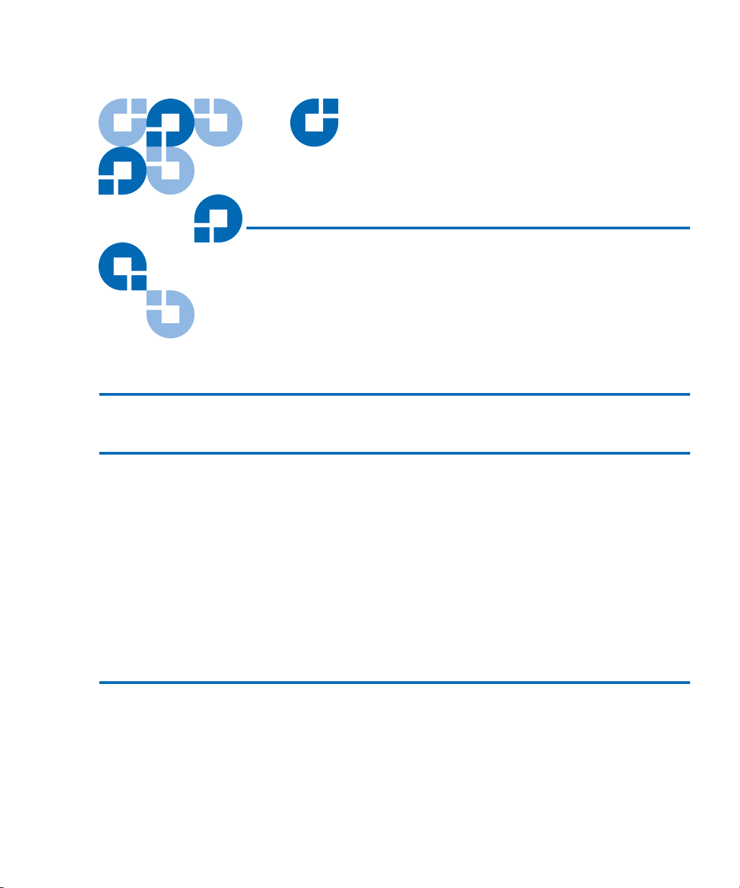
P4000 8/171 Model 1
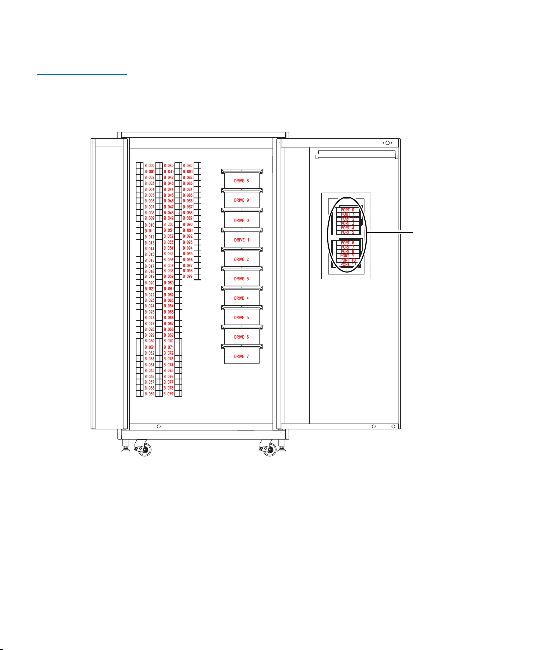
The P4000 8/171 model stores cartridges in the following locations:
•Up to 8 tape drives
• 171 storage bins on back wall
•One load port
• 8 shelf bins - two stationary LTO load port shelf bin modules (4
shelf bins each) are built into the load port assembly.
• 12 shelf bins - DLT and SDLT tape cartridges use two removable
6-cartridge magazines
Quantum P4000 and P7000 Libraries User’s Guide 5
Page 26
Chapter 1 Library Description
Overview
Figure 1 shows the storage bin, load port bin, and tape drive numbering
conventions. These conventions are used by the library GUI and the
diagnostic software program.
Figure 1 Bin Shelf
Numbering
Conventions P4000 8/
171
Load
port
6 Quantum P4000 and P7000 Libraries User’s Guide
Page 27

Chapter 1 Library Description
Overview
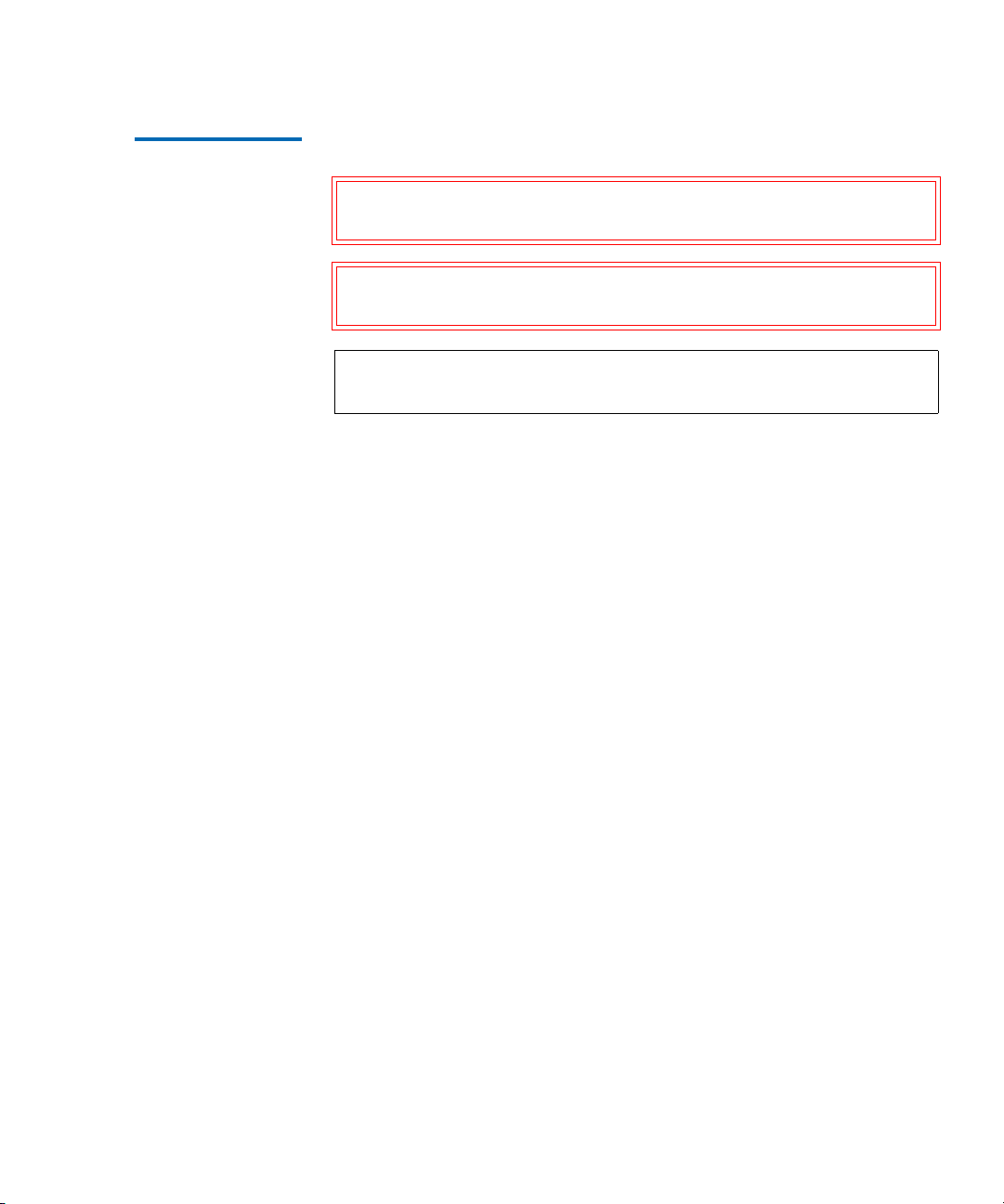
P4000 8/322 Model 1
The P4000 8/322 model stores cartridges in the following locations:
•Up to 8 tape drives
• 171 storage bins on back wall
• 111 shelf bins on inside of right door
• 40 shelf bins on inside of left door
•One load port
• 8 shelf bins - two stationary LTO load port shelf bin modules
(4 shelf bins each) are built into the load port assembly
• 12 shelf bins - DLT and SDLT tape cartridges use two removable
6-cartridge magazines
Figure 2
shows the storage bin, load port bin, and tape drive numbering
conventions. These conventions are used by the library GUI and the
diagnostic software program.
Quantum P4000 and P7000 Libraries User’s Guide 7
Page 28
Chapter 1 Library Description
Overview
Figure 2 Bin Shelf
Numbering
Conventions P4000 8/
322
Load
port
8 Quantum P4000 and P7000 Libraries User’s Guide
Page 29

Chapter 1 Library Description
Overview
P4000 10/100 Model 1
The P4000 10/100 model stores cartridges in the following locations:
• Up to 10 tape drives
• 100 storage bins on back wall
•One load port
• 8 shelf bins - two stationary LTO load port shelf bin modules
(4 shelf bins each) are built into the load port assembly
• 12 shelf bins - DLT and SDLT tape cartridges use two removable
6-cartridge magazines
Figure 3
shows the storage bin, load port bin, and tape drive numbering
conventions. These conventions are used by the library GUI and the
diagnostic software program.
Quantum P4000 and P7000 Libraries User’s Guide 9
Page 30
Chapter 1 Library Description
Overview
Figure 3 Bin Shelf
Numbering
Conventions P4000
10/100
Load
port
P4000 10/165 Model 1
The P4000 10/165 model stores cartridges in the following locations:
• Up to 10 tape drives
• 165 storage bins on back wall
•One load port
10 Quantum P4000 and P7000 Libraries User’s Guide
Page 31

Chapter 1 Library Description
Overview
• 8 shelf bins - two stationary LTO load port shelf bin modules
(4 shelf bins each) are built into the load port assembly
• 12 shelf bins - DLT and SDLT tape cartridges use two removable
6-cartridge magazines
Figure 4 Bin Shelf
Numbering
Conventions P4000
10/165
Figure 4
shows the storage bin, load port bin, and tape drive numbering
conventions. These conventions are used by the library GUI and the
diagnostic software program.
Load
port
Quantum P4000 and P7000 Libraries User’s Guide 11
Page 32

Chapter 1 Library Description
Overview
P4000 10/316 Model 1
The P4000 10/316 model stores cartridges in the following locations:
• Up to 10 tape drives
• 165 storage bins on back wall
• 111 shelf bins on inside of right door
• 40 shelf bins on inside of left door
•One load port
• 8 shelf bins - two stationary LTO load port shelf bin modules
(4 shelf bins each) are built into the load port assembly
• 12 shelf bins - DLT and SDLT tape cartridges use two removable
6-cartridge magazines
Figure 5
shows the storage bin, load port bin, and tape drive numbering
conventions. These conventions are used by the library GUI and the
diagnostic software program.
12 Quantum P4000 and P7000 Libraries User’s Guide
Page 33
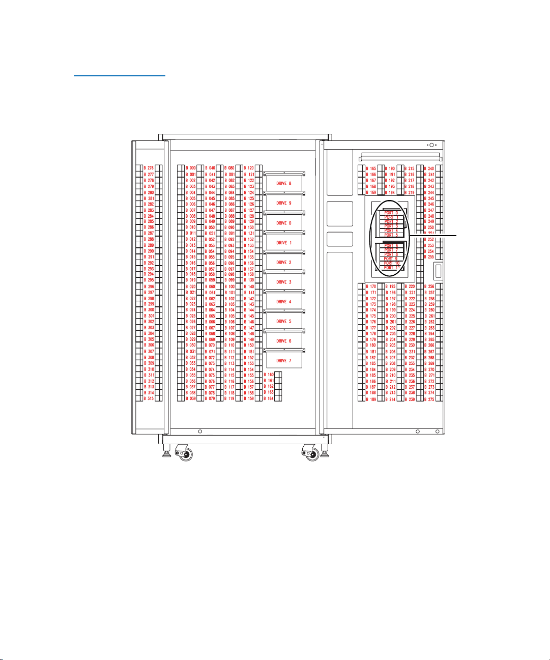
Figure 5 Bin Shelf
Numbering
Conventions P4000
10/316
Chapter 1 Library Description
Overview
Load
port
P7000 16/399 Model 1
The P7000 16/399 model stores cartridges in the following locations:
• Up to 16 tape drives
• 288 storage bins on back wall
• 111 shelf bins on inside of right door
•One load port
Quantum P4000 and P7000 Libraries User’s Guide 13
Page 34

Chapter 1 Library Description
Overview
• 8 shelf bins - two stationary LTO load port shelf bin modules
(4 shelf bins each) are built into the load port assembly.
• 12 shelf bins - DLT and SDLT tape cartridges use two removable
6-cartridge magazines
Figure 6 Bin Shelf
Numbering
Conventions P7000
16/399
Figure 6
shows the storage bin, load port bin, and tape drive numbering
conventions. These conventions are used by the library GUI and the
diagnostic software program.
Load
port
14 Quantum P4000 and P7000 Libraries User’s Guide
Page 35

Chapter 1 Library Description
Overview
P7000 16/555 Model 1
The P7000 16/555 model stores cartridges in the following locations:
• Up to 16 tape drives
• 288 storage bins on back wall
• 111 shelf bins on inside of right door
• 156 shelf bins on inside of left door
•One load port
• 8 shelf bins - two stationary LTO load port shelf bin modules
(4 shelf bins each) are built into the load port assembly
• 12 shelf bins - DLT and SDLT tape cartridges use two removable
6-cartridge magazines
• If the library is configured with both DLT and LTO tape drives,
stationary LTO load port shelf bin modules are used
Figure 7
shows the storage bin, load port bin, and tape drive numbering
conventions. These conventions are used by the library GUI and the
diagnostic software program.
Quantum P4000 and P7000 Libraries User’s Guide 15
Page 36

Chapter 1 Library Description
Overview
Figure 7 Bin Shelf
Numbering
Conventions P7000
16/555
Load
port
P7000 8/679 Model 1
The P7000 8/679 model stores cartridges in the following locations:
•Up to 8 tape drives
• 372 storage bins on back wall
• 111 shelf bins on inside of right door
• 196 shelf bins on inside of left door
•One load port
16 Quantum P4000 and P7000 Libraries User’s Guide
Page 37

Chapter 1 Library Description
Overview
• 8 shelf bins - two stationary LTO load port shelf bin modules
(4 shelf bins each) are built into the load port assembly
• 12 shelf bins - DLT and SDLT tape cartridges use two removable
6-cartridge magazines
• If the library is configured with both DLT and LTO tape drives,
stationary LTO load port shelf bin modules are used
Figure 8
shows the storage bin, load port bin, and tape drive numbering
conventions. These conventions are used by the library GUI and the
diagnostic software program.
Quantum P4000 and P7000 Libraries User’s Guide 17
Page 38

Chapter 1 Library Description
Overview
Figure 8 Bin Shelf
Numbering
Conventions P7000 8/
679
Load
port
18 Quantum P4000 and P7000 Libraries User’s Guide
Page 39

Chapter 1 Library Description
Features and Benefits
Features and Benefits 1
The P4000 and P7000 provides the following features and benefits:
• High-capacity, high-performance data storage and retrieval
• The library may house up to:
• 322 tape cartridges and 10 tape drives in a P4000
• 555 tape cartridges and 16 tape drives or 679 tape cartridges
and 8 tape drives in a P7000
• Expandable library configurations
• Access to future expandability and technology upgrades through
Quantum’s Prism Storage Architecture™
• Prism Storage Architecture employs standard PCI bus
technology to provide greater upgrade flexibility at reduced costs
• This technology ensures compatibility with future on-board
technologies such as tape drive controllers, high-speed host and
network interfaces, as well as server and tape RAID
• Reliable, versatile 120-240 volt AC auto-switching power supplies
• Hot-swappable, redundant DC power supplies ensure library
operations against power supply failure
• An optional advanced cooling system is available to prevent failures
from overheating
• On-line cartridge exchanges: load port with two removable,
6-cartridge magazines for easy insertion of cartridges without
interrupting library operations
• Easy serviceability and manageability
• Hot-swappable drives, DC power supplies, and fans enable field
service engineers to make repairs without taking the library offline
• Easy access and replacement of critical components
• A user-friendly GUI provides a wide range of configuration and
service-related functions
Quantum P4000 and P7000 Libraries User’s Guide 19
Page 40

Chapter 1 Library Description
Library Components
Library Components 1
The P4000 and P7000 libraries consist of these major components:
•Cabinet
•GUI
• Intelligrip™ mixed-media cartridge handling mechanism
• Mixed-media tape drives (DLT and SDLT, or DLT and LTO)
•Load port
Cabinet 1 The cabinet houses all library components including:
• Cartridge handling mechanism (CHM)
•Storage bins
• Control electronics
• Power supply and distribution equipment
•Fan modules
• Tape drives
You can access these components to monitor and control library
operation through the front doors and back panels of the library cabinet.
Front Panel 1
The front of the library cabinet (see figure 10
• Two front doors provide easy access to the CHM and the storage
array
• The viewing window makes it possible to visually monitor library
operations
• A GUI on the right side of the cabinet enables you to monitor and
control library operations
) provides the following:
20 Quantum P4000 and P7000 Libraries User’s Guide
Page 41

Figure 9 P4000
Cabinet-Front View
Chapter 1 Library Description
Library Components
Viewing
window
GUI
Power
switch
Door
Load
port
Quantum P4000 and P7000 Libraries User’s Guide 21
Page 42

Chapter 1 Library Description
Library Components
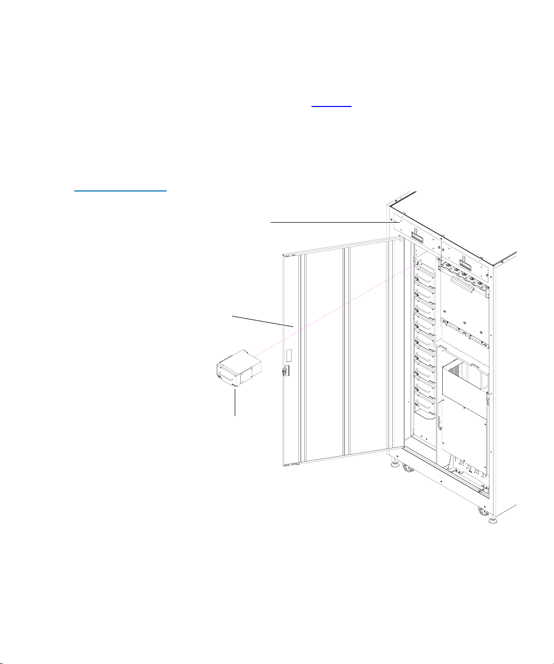
Figure 10 P7000
Cabinet-Front View
Viewing
window
Dual
doors
GUI
Power
switch
Load
port
• A mixed media load port equipped with either two 4-cartridge
stationary load packs for libraries configured with LTO tape drives,
or two 6-cartridge removable load pack magazines for DLT and/or
SDLT tape drives, provides easy insertion of additional tape
cartridges while the library is in operation.
• The power switch for the library is located behind a sliding panel on
the right front door.
22 Quantum P4000 and P7000 Libraries User’s Guide
Page 43
Chapter 1 Library Description
Library Components
Cabinet-Back 1
Figure 11 P4000
Cabinet-Back Panels
The back of the cabinet (see figure 11
) provides easy accessibility to:
• Cooling fans
• Power, control, and data interfaces
• Tape drives
Hot swap,
removable fans
Easy-access
panel
Hot-swappable
drives in
removable
canisters
Unit shown with ten drive upgrade
Quantum P4000 and P7000 Libraries User’s Guide 23
Page 44

Chapter 1 Library Description
Library Components
Figure 12 P7000
Cabinet - Back Panels
Hot swap,
removable fans
Easy-access
panel
Hot-swappable
drives in
removable
canisters
GUI 1 The GUI features a menu system for determining library status,
configuring the library, and performing certain diagnostic functions.
The GUI screen (see figure 13
) consists of:
• Horizontal taskbar (top row)
• Vertical taskbar (left column)
• Main display area
24 Quantum P4000 and P7000 Libraries User’s Guide
Page 45

Chapter 1 Library Description
Library Components
Figure 13 GUI—Initial
Screen (P7000)
Vertical
task bar
Back Forward
Horizontal
task bar
Home
About
System
state
display
Standby
Load
port
Security
indicator/
switch
System
Off-line
Standby
Load Port
U
Stop
The horizontal taskbar provides left and right arrow buttons to scroll
through the tabs for status, configuration, diagnostic, and operating
controls options.
Overview Tapes Operator
P7000
Main display area
The vertical taskbar provides various library controls:
• System state display - indicates current tasks and requests in process.
• Standby - takes the library “off-line” or “on-line”.
• Load port button - submits request to the library to open the load
port.
• Security level indicator - shows “locked” on start-up and
initialization (default).
• Stop button - immediately removes power from the library robotics.
Quantum P4000 and P7000 Libraries User’s Guide 25
Page 46
Chapter 1 Library Description
Library Components
IntelliGripTM Mixed Media CHM 1
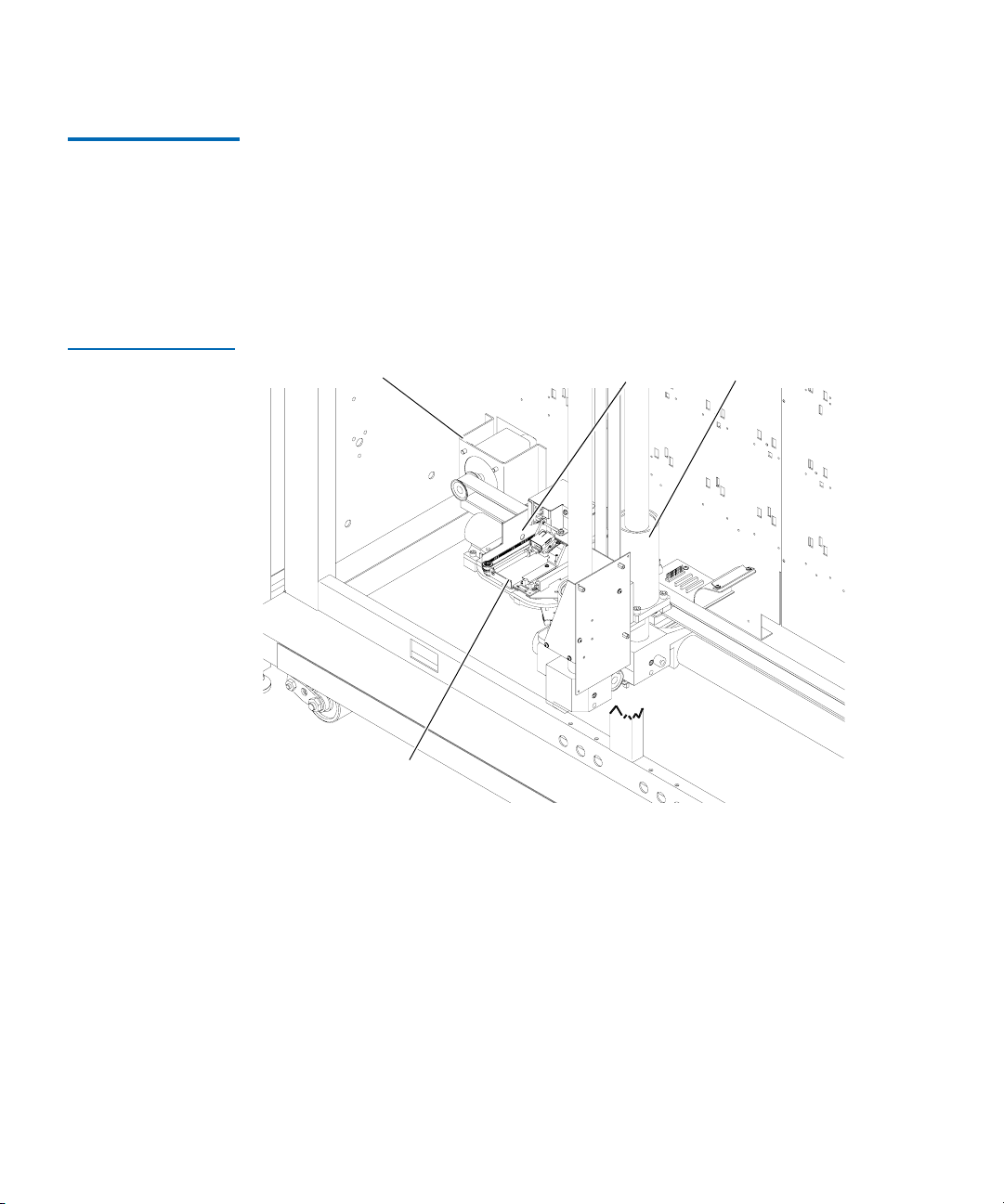
Figure 14 Advanced
Robotics System
The CHM of the library consists of the following components:
• Mixed media gripper assembly
• Vertical carriage assembly
• Horizontal drive motor
• Extension axis assembly
Horizontal drive
motor
Mixed media
gripper assembly
Vertical carriage
assembly
Extension access
assembly
The vertical and horizontal actuators move the mixed media gripper into
position to pick and place tape cartridges. The rotary actuator rotates the
mixed media gripper 180°, allowing the mixed media gripper to pass
cartridges between the front storage bins and the back storage bins or
tape drives. The extension actuator extends the mixed media gripper
forward to make contact with the desired cartridge and then retracts the
mixed media gripper to remove the cartridge from a bin or drive.
26 Quantum P4000 and P7000 Libraries User’s Guide
Page 47
Chapter 1 Library Description
Library Components
The mixed media gripper includes a Class II laser bar code scanner that
reads standard six-character (7 characters for SDLT and 8 characters for
LTO), 3 of 9 bar code labels. The scanner is used to maintain an inventory
of the tape cartridges within the library. An inventory occurs
automatically whenever the library is turned on or after the bulk load
door has been closed. An inventory can also be initiated from the host
computer.
Although the library does not require tape cartridges to have bar code
labels, properly labeled tape cartridges and full storage bins speed up the
inventory process.
Tape Drives 1 The P4000 can hold up to 10 tape drives and the P7000 can hold up to 16
tape drives, including combinations of DLT and SDLT, or DLT and LTO.
Table 15 Tape Drive
and Cartridge
Specifications
Tape
Cartridge
Quantum
DLT 8000
Quantum
SDLT-220
Quantum
SDLT-320
Quantum
SDLT-600
Transfer
Rate
6 MB/
sec
11 MB/
sec
16 MB/
sec
36 MB/
sec
IBM LTO1 15 MB/
sec
IBM LTO2 35 MG/
sec
HP LTO2 30 MB/
sec
Cartridge
Capacity
Cartridge
Capacity
(compressed)
Total Library
(P7000) Capacity
(679 bins)
Library
Capacity
(compressed*)
40 GB 80 GB 27.16 TB 54.32 TB
110 GB 220 GB 74.69 TB 149.38 TB
160 GB 320 GB 108.64 TB 217.28 TB
300 GB 600 GB 203.7 TB 407.4 TB
100 GB 200 GB 67.9 TB 135.8 TB
200 GB 400 GB 135.8 TB 271.6 TB
200 GB 400 GB 135.8 TB 271.6 TB
* Compressed capacity assumes a 2:1 compression ratio.
Quantum P4000 and P7000 Libraries User’s Guide 27
Page 48

Chapter 1 Library Description
Library Components
When fewer than 8 drives are installed in a P4000 or fewer than 16 tape
drives are installed in a P7000, the tape drives must occupy consecutive
drive bays, beginning with drive bay 0.
The drives used in both the P4000 and P7000 are more reliable than
standard drives due to the automated environment.
Both the P4000 and P7000 can be populated simultaneously with DLT,
SDLT, or LTO tape drives.
If a drive experiences read/write errors when the AutoClean function is
enabled, the library issues an error message stating that drive cleaning is
required. Without user intervention, the IntelliGrip CHM replaces the
data cartridge with a cleaning cartridge. When the cleaning procedure
finishes, the CHM returns the data cartridge to the drive.
Note: When a DLT cleaning cartridge has completed its 20-use limit,
it is automatically exported from the library, requiring a new
one to be loaded through the load port.
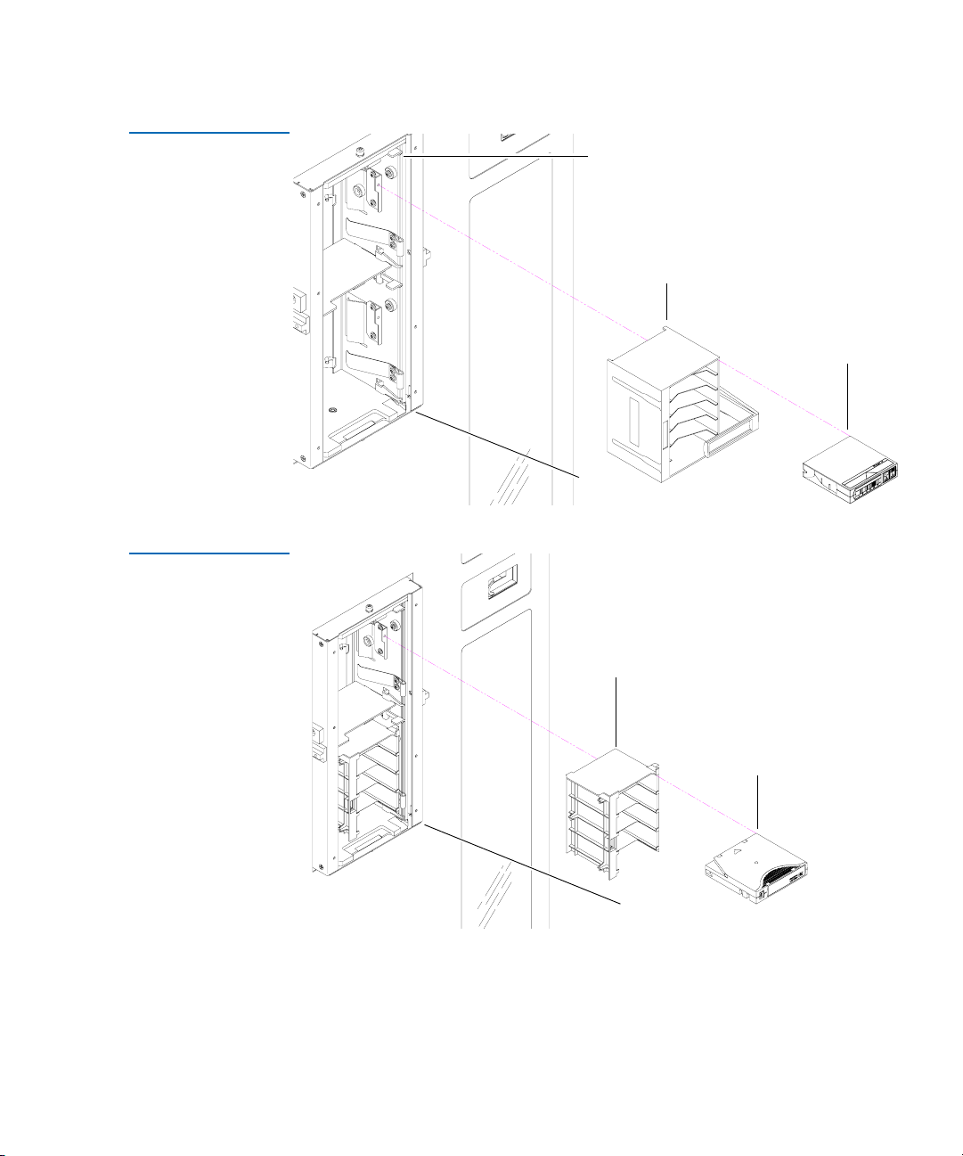
Load Port and Magazines 1
The load port is a mechanical device in the front panel of the library that
enables you to import or export tape cartridges to and from the library
via two tape cartridge magazines without interrupting library operations.
The DLT/SDLT load port uses two removable 6-bin tape cartridge
magazines (see figure 15
).
The LTO load port uses two stationary 4-bin tape cartridge magazines
(see figure 16
).
28 Quantum P4000 and P7000 Libraries User’s Guide
Page 49
Chapter 1 Library Description
Library Components
Figure 15 DLT/SDLT
Load Port
Figure 16 LTO Load
Port
Metal tab
6-bin
magazine
DLT/SDLT
cartridge
Load port
assembly
Stationary
4-bin
magazine
LTO
cartridge
Load port
assembly
Quantum P4000 and P7000 Libraries User’s Guide 29
Page 50

Chapter 1 Library Description
Library Components
30 Quantum P4000 and P7000 Libraries User’s Guide
Page 51

Chapter 2
2Basic Library Operations
This chapter provides an overview of the graphical user interface (GUI)
and describes the following basic library operating procedures:
• Installing Tape Cartridges
• Preparing the Library for Operation
• Turning the Library On and Off
• Using the GUI
• Obtaining Library Status
• Changing the GUI Security Levels
• Operating the Load Port
• Inserting Tape Cartridges into the Load Port
• Manually Ejecting a Tape Cartridge
Quantum P4000 and P7000 Libraries User’s Guide 31
Page 52
Chapter 2 Basic Library Operations
Installing Tape Cartridges
Installing Tape Cartridges 2
To install tape cartridges
1 Label each cartridge.
2 Set the write-protect switch.
3 Place cartridges in the fixed bins.
Caution: Handle tape cartridges with care. Do not drop or bang
them, or place them near sources of electromagnetic
interference. Rough handling can displace the tape
leader, making the cartridge unusable and potentially
hazardous to the tape drives.
Taking ESD Precautions 2
Components within the P4000 or P7000 contain static-sensitive parts. To
prevent damage to these parts while performing installation,
maintenance, or replacement procedures, observe the following
precautions:
• Keep the library turned off during all installation, maintenance, and
replacement procedures.
Note: Hosts without a direct SCSI, Fibre Channel, or Gigabit
Ethernet interface require external communications bus
converters.
• Keep the library power cord connected to a grounded power outlet
except when working with AC electrical components.
Warning: Avoid contact with the power supplies, EMI filter,
and all other AC electrical components while the
library is connected to a power outlet.
• Use an antistatic wrist strap when touching internal library
components. To use the wrist strap properly, place the band around
your wrist and attach the clip to the library frame. Keep the strap on
until you are ready to close the library doors.
32 Quantum P4000 and P7000 Libraries User’s Guide
Page 53

Chapter 2 Basic Library Operations
Installing Tape Cartridges
• Keep static-sensitive parts in their shipping containers until ready for
installation.
• Do not place static-sensitive parts on any metal surface. If you need to
put down a static-sensitive part, place it inside its protective shipping
bag or on a grounded antistatic mat.
• Avoid direct contact with static-sensitive parts. Avoid touching
connectors and discrete components.
• Close library door and access panel when not working on the library.
• Be very careful when installing the library or handling components in
dry climates or environments where cold weather heating is used.
Environments such as these with lower relative humidity have
greater potential to produce static electricity.
Note: In environments with high potential for static electricity,
take additional precautions such as the use of an antistatic
smock or a grounded antistatic mat.
DLT/SDLT Cartridges 2
The following shows you how to label DLT/SDLT tape cartridges, as well
as setting the write-protect switch and proper orientation.
Labeling 2
Attaching a bar code label to each tape cartridge enables the library to
identify the cartridge quickly, thereby speeding up inventory time.
Place the label in the slide-in slot on the front of the cartridge (see
figure 17
Quantum P4000 and P7000 Libraries User’s Guide 33
).
Page 54

Chapter 2 Basic Library Operations
Installing Tape Cartridges
Figure 17 Inserting a
Bar Code Label (DLT/
SDL T)
Slide-in slot
Note: Only use bar code labels that have been designed for
Setting the Write-Protect Switch 2
Each tape cartridge has a write-protect switch similar to that shown in
figure 18
cartridge (write-enabled) or whether data on the cartridge is protected
from being erased or overwritten (write-protected).
cartridges. Do not adhere labels to a cartridge anywhere
except the slide-in slot.
. This switch determines whether new data can be written to the
Proper Insertion Orientation 2
Refer to figure 18
for proper label placement, write protection settings
and insertion orientation.
34 Quantum P4000 and P7000 Libraries User’s Guide
Page 55

Figure 18 DLT and
AFL053
DLTtape IV
SDL T Cartridges
Chapter 2 Basic Library Operations
Installing Tape Cartridges
Insert this end into the bin
Insertion arrow
Barcode label
Orange
window
Write
protect
Slide left Slide right (default)
Write
enable
(DLT cartridge shown)
LTO Cartridges 2 LTO tape cartridges are different in size to the DLT/SDLT cartridges as
well as in the barcode labeling and write-protect switch setting (see
figure 19
).
Adhesive-backed bar code labels are used on LTO tape cartridges. Refer
to figure 11 for proper label placement, write protection settings and
insertion orientation.
Quantum P4000 and P7000 Libraries User’s Guide 35
Page 56

Chapter 2 Basic Library Operations
Installing Tape Cartridges
Figure 19 LTO
Cartridge
Write Protect
Switch
Slide left
(default)
Write
enable
Write
protect
Slide right
Barcode label
Insert this end into the bin
Insertion arrow
ABC123L1
Caution: LTO tape drive media cannot be degaussed due to the fact
that it uses “magnetic servos”. Do not attempt to degauss
LTO tape drive media. If this media is degaussed, it will
no longer work.
Placing Tape Cartridges in the Library 2
Place a tape cartridge in each fixed storage bin on the back wall of the
library and on the inside of the front doors. Be sure all cartridges are
properly oriented with the barcode facing you and that they are fully
seated in the bins.
36 Quantum P4000 and P7000 Libraries User’s Guide
Page 57

Chapter 2 Basic Library Operations
Preparing the Library for Operation
Preparing the Library for Operation 2
To prepare the library for operation:
• Close the library doors and access panels
• Connect the host workstations
Closing the Library Doors and Access Panels 2
Connecting Host Workstations 2
The library has two front doors (P7000 only) and three back access panels.
1 Close and lock the front doors.
a Close one door and then the other.
b Turn the door latches to secure the doors to the library frame.
c Lower the latches over the door locks.
d Using the key from the accessory kit, lock the latches in place.
2 Close and lock the back access panels using a 5/32 hex wrench (not
provided).
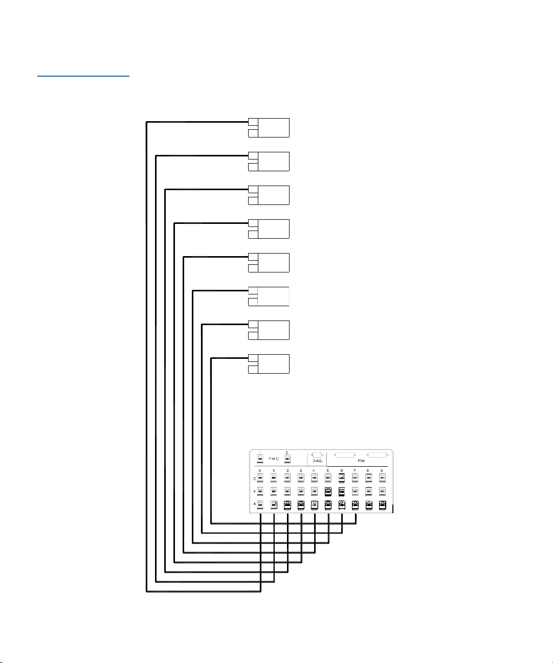
Connect the SCSI (or Ethernet) cables and jumpers as shown in the
applicable figures.
Note: Quantum ships sufficient SCSI cables and terminators with
this library to set up two-drives per SCSI bus, as well as
adequate SCSI jumper cables to accommodate up to 4 drives
per SCSI bus.
Figure 20
P4000 library.
shows the recommended cabling configuration for a 8-drive
Figure 21
P7000 library.
Figure 22
library.
Figure 23
library.
Quantum P4000 and P7000 Libraries User’s Guide 37
shows the recommended cabling configuration for a 16-drive
shows the Ethernet cabling configuration for a 10-drive P4000
shows the Ethernet cabling configuration for a 16-drive P7000
Page 58

Chapter 2 Basic Library Operations
Preparing the Library for Operation
Figure 20 Cabling
Configuration 8 Drive
P4000
8 PLS
6330549-01
Drive Column 1
Tape drive
Drive position 0
SCSI ID 2
Tape drive
Drive position 1
SCSI ID 3
Tape drive
Drive position 2
SCSI ID 4
Tape drive
Drive position 3
SCSI ID 5
tape drive
Drive position 4
SCSI ID 2
Tape drive
Drive position 5
SCSI ID 3
Tape drive
Drive position 6
SCSI ID 4
Tape drive
Drive position 7
SCSI ID 5
Library electronics
SCSI ID 0
SCSI Port L SCSI Port K
6330549-01
0415891
SCSI diff. terminators
8 PLS
SCSI Port A
SCSI Port B
SCSI Port J
SCSI Port I
SCSI Port C
38 Quantum P4000 and P7000 Libraries User’s Guide
SCSI Port H
SCSI Port G
SCSI Port F
SCSI Port E
SCSI Port D
Page 59

Figure 21 Cabling
Configuration 16 Drive
P7000
Chapter 2 Basic Library Operations
Preparing the Library for Operation
Drive Column 1
Tape drive
Drive position 8
SCSI ID 2
Tape drive
Drive position 9
SCSI ID 3
Tape drive
Drive position 10
SCSI ID 4
Tape drive
Drive position 11
SCSI ID 5
tape drive
Drive position 12
SCSI ID 2
T ape drive
Drive position 13
SCSI ID 3
Tape drive
Drive position 14
SCSI ID 4
Tape drive
Drive position 15
SCSI ID 5
Library electronics
SCSI ID 0
Drive Column 0
Tape drive
Drive position 0
SCSI ID 2
Tape drive
Drive position 1
SCSI ID 3
Tape drive
Drive position 2
SCSI ID 4
Tape drive
Drive position 3
SCSI ID 5
Tape drive
Drive position 4
SCSI ID 2
Tape drive
Drive position 5
SCSI ID 3
Tape drive
Drive position 6
SCSI ID 4
Tape drive
Drive position 7
SCSI ID 5
0415891
SCSI diff. terminators
8 PLS
6330549-01
8 PLS
SCSI Port Q
SCSI Port R
SCSI Port P
SCSI Port O
SCSI Port N
SCSI Port M
SCSI Port L
SCSI Port K
SCSI Port J
SCSI Port I
6330549-01
SCSI Port A
SCSI Port D
SCSI Port B
SCSI Port C
SCSI Port H
SCSI Port G
SCSI Port F
SCSI Port E
Quantum P4000 and P7000 Libraries User’s Guide 39
Page 60
Chapter 2 Basic Library Operations
Dri
1
Preparing the Library for Operation
Figure 22 Ethernet
Cabling 8 Drive P4000
ve Column
0
1
2
3
4
5
6
7
Bulkhead
40 Quantum P4000 and P7000 Libraries User’s Guide
Page 61
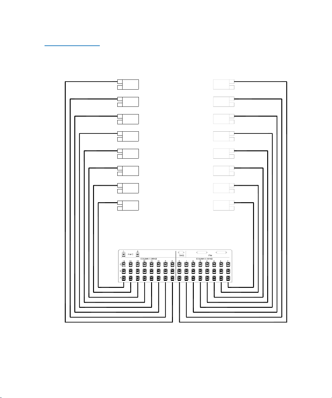
Figure 23 Ethernet
Cabling 16 Drive
P7000
Chapter 2 Basic Library Operations
Preparing the Library for Operation
Drive Column 1 Drive Column 0
8
0
10
11
12
13
14
15
9
Bulkhead
1
2
3
4
5
6
7
Quantum P4000 and P7000 Libraries User’s Guide 41
Page 62

Chapter 2 Basic Library Operations
Turning the Library On and Off
Turning the Library On and Off 2
This section explains how to:
• Turn on the library
• Place the library on-line or off-line
• Turn off the library
• Test the installation
Turning On the Library 2
Placing the Library On-line or Off-line2
Turning Off the Library 2
To turn on the library:
1 Verify that:
• Power cables are firmly in place
• All doors are closed
2 Turn on the power switch located behind the small sliding door
below the GUI.
3 After several seconds, verify that the current state of the library
(“System On-line” or “System Off-line”) appears in the System State
display on the GUI (see figure 24
With the library turned on, press the Standby button on the GUI.
Pressing the
line states.
To turn off the library:
1 Place the library off-line by pressing the
The library robotics completes any current commands and then
stops.
Standby button toggles the library between on-line and off-
).
Standby button.
2 Verify that the GUI display indicates “System Off-line.”
42 Quantum P4000 and P7000 Libraries User’s Guide
Page 63

Chapter 2 Basic Library Operations
Using the GUI
3 Verify that the CHM is empty by checking the Overview screen on the
GUI (see Chapter 3, Operator Commands
).
If there is a tape cartridge in the CHM, perform a
place the cartridge in an available bin.
4 Turn off the power switch located below the GUI.
Note: Wait ten seconds before turning on the power switch
again.
Move command to
Using the GUI 2
The GUI is activated by touching the screen, and is located on the front of
the library. The menus on the GUI allow you to obtain information about
the library, execute library commands, and test library functions (see
figure 24
The GUI’s functions are grouped into the following four screens:
•
•
).
Overview screen—displays current tape drive, CHM, and load port
content and activities.
Tape s screen—displays tape drive, storage bin, load port, and gripper
inventories.
•
Operator screen—contains library configuration and control functions
(password protected).
•
Service screen—contains reporting functions, system tests, and
service commands (password protected).
Quantum P4000 and P7000 Libraries User’s Guide 43
Page 64

Chapter 2 Basic Library Operations
Using the GUI
Figure 24 GUI—Initial
Screen
Back Forward
Home
About
Overview Tapes Operator
System
Off-line
Standby
Load Port
P7000
U
Stop
Table 16 GUI Components lays out the various functions of the GUI.
44 Quantum P4000 and P7000 Libraries User’s Guide
Page 65

Chapter 2 Basic Library Operations
Using the GUI
Table 16 GUI
Components
Overview
Screen
Status display
• Tape drives
• Activity
•Load port
Tapes
Screen Operator Screen* Service Screen*
Inventory
display
•Tape
drives
•Storage
bins
•Load port
• Transport
(CHM)
Configure
•Configure Library
• Configure Options
• Control
• Move Cartridges
•Inventory Tapes
• Calibrate Library
•Unload Drive
• Unload Imp/Exp
(CHM)
*These screens are password protected.
Reports
• Statistics
•Actuator
• SysTest Results
•Auto Clean
•Tests
• SysTest Library
• Miscellaneous
• Initialize
Nonvol Stats
• Initialize
Nonvol Config
•Change
Password
Opening a Screen2 To open one of the four main screens, touch the desired tab at the top of
the GUI. The
Overview and Tape s screens are accessible to any user. The
Operator and Service screens require a password.
Once the desired screen appears on the GUI, you can view information or
press buttons to execute commands and open other screens.
Library Status Information 2
Some information about the library firmware version, security status, and
library status can be found on the left side of the GUI.
• Company logo—displays a company information screen when
pressed, as well as the application level and boot block level.
• System state display—shows the current state of the library (system online, system off-line, system stopped, door open, and so on).
Quantum P4000 and P7000 Libraries User’s Guide 45
Page 66

Chapter 2 Basic Library Operations
Load Port
System
Off-line
Standby
Overview Tapes Operator
Back Forward
Home
U
Stop
About
P7000
Using the GUI
• Lock icon—shows the current security level at the GUI. Five security
levels are available: service (S), operator (O), user (U), import only (I),
and locked (L). Table 17
describes the attributes of each security level.
Figure 25 Library
Status Indicators
Exiting a Screen 2 To exit any screen, press the Back or Home button.
Company logo
System
state
display
Lock
icon
While the command is executing, the GUI displays a Command In
Progress dialog box with an
command and stops the ongoing operation.
Abort button. Pressing Abort cancels the
After pressing
the screen associated with the aborted command.
Abort, it is still necessary to press the Back button to exit
Library Controls 2 Library controls are located along the top and left side of the GUI in the
horizontal and vertical bars (see figure 26
).
46 Quantum P4000 and P7000 Libraries User’s Guide
Page 67

Chapter 2 Basic Library Operations
Load Port
System
Off-line
Standby
Overview Tapes Operator
Back Forward
Home
U
Stop
About
P7000
Using the GUI
Figure 26 Library
Controls
Standby
button
Load Port
button
Stop
button
Back Forward Home
These controls function as follows:
•
Home button—returns to the home (initial) screen.
Contrast
•
Forward button—moves forward screen by screen through previous
selections.
•
Back button—moves backward screen by screen through previous
selections.
•
Contrast buttons—adjust the contrast of the GUI screen.
•
Standby button—toggles the library between on-line and off-line
states.
•
Load Port button—releases and locks the load port door. If the load
port is locked in the closed position, pressing this button releases the
load port and then locks the door. If the load port is locked in the
open position, pressing this button unlocks the load port, allowing
you to rotate the load port to the closed position where it
automatically locks.
Quantum P4000 and P7000 Libraries User’s Guide 47
Page 68

Chapter 2 Basic Library Operations
Obtaining Library Status
• Stop button—halts library activity immediately by cutting power to
library robotics. Pressing the Stop button a second time restores
power to library robotics.
Note: The default passwords are:
• Service “5678”
• Operator “1234”
• User “2222”
• Import Only “1111”
For more information on password and security levels, refer to Changing
the GUI Security Levels on page 52.
Obtaining Library Status 2
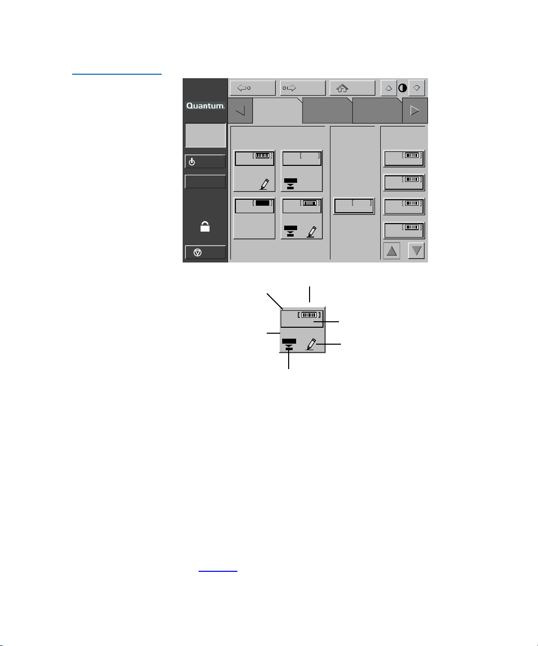
The
Overview and Tape s screens on the GUI provide library status. The
Overview screen displays a “snapshot” of the tape drive, robot activity,
and load port inventory (see figure 27
inventory of all elements in the library (see figure 29
To display the Overview or Tapes screen, press the appropriate tab on the
GUI.
Overview Screen 2 The Overview screen provides information for the following items:
•Drives
•Activity
•Load port
48 Quantum P4000 and P7000 Libraries User’s Guide
). The Tap es screen displays the
).
Page 69
Chapter 2 Basic Library Operations
Obtaining Library Status
Figure 27 Overview
Screen
About
System
Off-line
Standby
Load Port
U
Stop
Back Forward
Overview Tapes Operator
Drives Activity Load Pack
D00
ANF 120
Ready
D01
???
Ready
D02
empty
Ready
D03
ANF 123
Ready
GRP
empty
Home
P00
ANF146
P01
ANF147
P02
ANF148
P03
ANF149
Cartridge
Element
present
number
Bar code
number
Write-
Element
status
D03
ANF 123
Ready
enabled
Compression
enabled
Drives 2
The Drives area reports whether:
• A tape drive contains a tape cartridge
• The tape cartridge is write-enabled or write-protected
• Compression is enabled
It also displays the bar code number of the cartridge.
For a more detailed screen showing an individual drive’s status, press the
screen anywhere in the Drives area to display the
(see figure 28
). Use the arrow buttons at the bottom of the screen to scroll
Tape Drive Status screen
to the desired drive.
Quantum P4000 and P7000 Libraries User’s Guide 49
Page 70

Chapter 2 Basic Library Operations
Obtaining Library Status
Figure 28 Tape Drive
Status Screen
About
Back Forward
Home
TapesOverview Operator ServiceOverview
System
Off-line
Standby
Load Port
U
Tape Drive Status
D03
D00
ANF 123
ANF 120
Ready
DLT 8000 SCSI ID: 05
D02
CompacTape IV, 35/70 Gb
???
Drive Code Rev: 000037
Ready
Controller Code Rev: 96
S/N: JF71100038
Ready
D01
Compression ON
Write Protect OFF
EMPTY
Ready
D03
ANF 123
Ready
Prevent: OFF
Cleaning Required: OFF
Cleaning Requested: OFF
Tape Remain: 033729 MB
Compr Ratio (R): N/A
Compr Ratio (W): N/A
Clean Cart Loads: 0000005
Hrs Since Cleaned: 00326
Clean Tape Used 000 times
Stop
To return to the Overview screen, press the screen anywhere in the Tape
Drive Status box.
Activity 2
The Activity area shows the source element, the transport medium, and
the destination element involved in the activity; the current location of
the tape cartridge; and the progress of the activity.
Load Port 2
The Load Port area identifies tape cartridges currently stored in either
magazine in the load port. Use the arrow button to view contents not
currently displayed.
50 Quantum P4000 and P7000 Libraries User’s Guide
Page 71
Chapter 2 Basic Library Operations
Obtaining Library Status
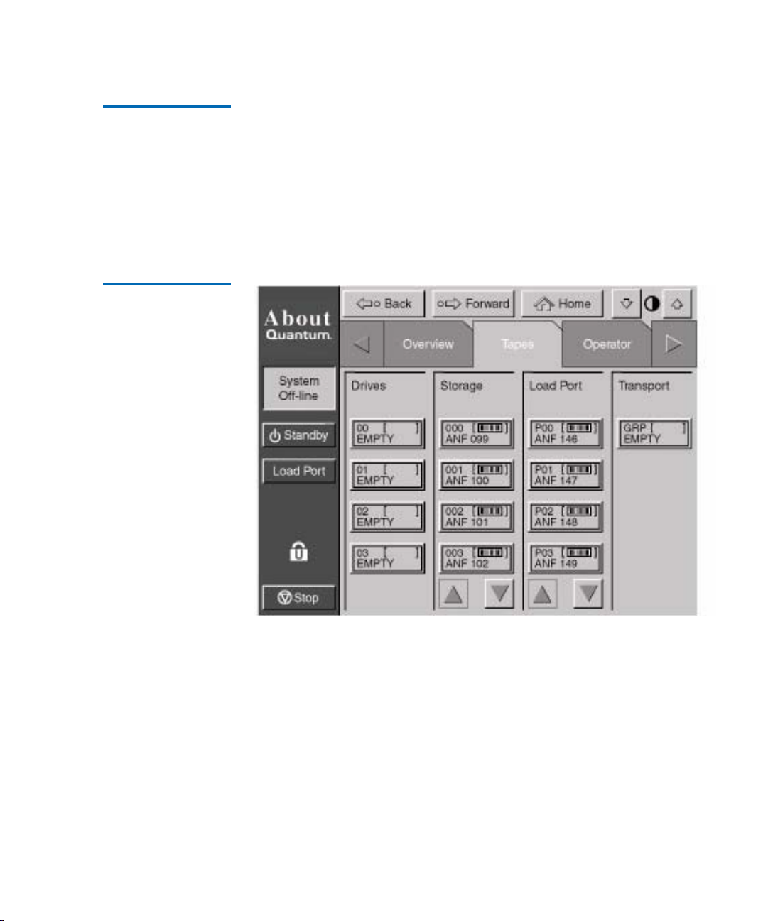
Tapes Screen 2 The Tapes screen identifies the tape cartridges residing in the following
elements:
•Drives
• Storage (fixed storage bins)
•Load port
• Transport (gripper)
Figure 29 Tapes
Screen
Viewing Storage and Load Port Elements 2
The Drives, Storage, and Load Port categories may contain too many
elements to display at once. To scroll through these elements, use the
arrow buttons at the bottom of each category.
You can also expand the Drives, Storage, or Load Port list to fill the screen
by touching the desired category anywhere above the scrolling arrows.
To return to the start of the Tapes screen, press the
Quantum P4000 and P7000 Libraries User’s Guide 51
Back button.
Page 72

Chapter 2 Basic Library Operations
Changing the GUI Security Levels
Changing the GUI Security Levels 2
There are five levels of security for the P4000 and P7000 GUI (see
table 17
):
Table 17 Security
Levels (listed from
highest to lowest)
.
Lock
Icon
Level
Indicator
• Service (S)—provides access to both the
Operator and Service set of
screens and all functions on the system bar.
• Operator (O)—provides access to the
Operator set of screens and all
functions on the system bar.
• User (U)—provides access to screens that are not password-protected
(
Overview and Tape s screens) and all functions on the status bar.
• Import Only (I)—provides access to
the
Load Port button on the system bar (no Stop or Standby).
• Locked(L)—provides access to
Overview and Tapes screens and
Overview and Tape s screens only.
The security level indicator (lock icon) at the lower left corner of the GUI
indicates the current security level (S, O, U, I, or L)..
Password
Protected
Overvie
w Screen
Access
Tap es
Screen
Access
Operat
or
Screen
Access
Service
Screen
Access
Load
Port
Access
Stop
and
Standby
Access
Service S Yes Yes Yes Yes Yes Yes Yes
Operator O Yes Yes Yes Yes No Yes Yes
User U Yes Yes Yes No No Yes Yes
MultiUnit
Import
Only
Locked L No Yes Yes No No No No
52 Quantum P4000 and P7000 Libraries User’s Guide
O Yes No No No No No No
I Yes Yes Yes No No Yes No
Page 73

Chapter 2 Basic Library Operations
Changing the GUI Security Levels
Securing the GUI 2 When the User security level is set, access is restricted to the Operator and
Service screens. Since these screens control library configuration, testing,
and initializing functions, the User security level is appropriate default
condition for routine library operation.
Changing Security Levels 2
To change security levels:
1 Press the Lock icon.
Figure 30 Password
Screen
The Password screen appears (see figure 30
).
2 Press the desired security level button (Service, Operator, User,
Import Only, or Locked).
About
System
Off-line
Standby
Load Port
Back Forward
Operator
Enter Password
Enter Password: _
Tapes
Home
Service
1 2
3 4
5 6
7 8
9 0
O
Stop
Enter
3 Enter a password if necessary.
A password is required to enter a higher security level than the
current level.
Quantum P4000 and P7000 Libraries User’s Guide 53
Page 74

Chapter 2 Basic Library Operations
Operating the Load Port
4 Press the Select button.
A screen appears indicating that the new security level has been set
successfully.
5 Press
Okay.
The lock icon displays the new security level (S, O, U, I, or L).
Note: This procedure is especially useful to change from
Operator or Service levels to the User level after executing
an Operator or Service level command.
Note: If the GUI is accessed from the Service (S) or Operator (O)
level, and no activity has occurred for 15 minutes, the GUI
will return to the initial screen (see figure 24
).
Operating the Load Port 2
After pressing the
the lock on the load port (you will hear an audible ‘click’). The GUI
displays “Wait Open Load Port.” Pull on the load port’s handle. The load
port pulls outward about an inch to its unlocked position which allows its
interior drum to be rotated 180
Load Port button on the GUI, the library will release
o
for magazine loading or unloading.
Warning: Opening or closing the load port door presents mechanical
hazards. Use both hands to pull or push the load port
finger grip and use the top and bottom surfaces of the load
port drum to keep fingers out of load port openings when
rotating the load port drum (see figure 31
54 Quantum P4000 and P7000 Libraries User’s Guide
).
Page 75

Chapter 2 Basic Library Operations
Inserting Tape Cartridges into the Load Port
After loading or unloading the magazines, rotate the load port back 180o
and push the load port handle to lock the load port into position.
Note: The mixed media load port used with LTO tape cartridges has
two stationary 4-cartridge magazines built into the load port,
unlike the two removable 6-cartridge magazines used with
DLT and SDLT tape cartridges. If the library contains both
DLT and LTO tape drives, the stationary magazines are used
in the load port.
Removing/ Installing a Tape Cartridge Magazine 2
Loading a Tape Cartridge Magazine 2
To remove a DLT/SDLT magazine from the load port, press up on the
metal tab at the upper right corner of the load port bay. Rotate the
magazine handle from the top of the magazine toward you and pull the
magazine from the loadport. Reverse this procedure to install a magazine
(see figure 15
The magazine used with DLT/SDLT tape cartridges have keyed bins to
prevent improper cartridge insertions. They are equipped with springloaded mechanisms to capture or release a tape cartridge.
To insert a tape cartridge, push it into the magazine’s bin until you here a
click and the metal tab at the left side of the bin pops out.
To remove a tape cartridge, gently push the cartridge all the way into the
bin, then release. The cartridge will be partially ejected, making it easy to
remove.
on page 29).
Inserting Ta pe Cartridges into the Load Port 2
This section explains how to insert tape cartridges using the load port
mechanism.
Caution: Do not use CompacTape I, CompacTape II, or
CompacTape IIIXT cartridges in this library.
Quantum P4000 and P7000 Libraries User’s Guide 55
Page 76

Chapter 2 Basic Library Operations
Inserting Tape Cartridges into the Load Port
Inserting DLT and SDLT Tape Cartridges 2
DLT/SDLT tape cartridges are inserted into two removable 6-cartridge
magazines as shown in figure 15
on page 29. Tape cartridges may be
loaded to or unloaded from a magazine with the magazine in or out of
the library.
To insert a DLT tape cartridge into a magazine:
Note: To move cartridges to the load port for removal, refer to
Moving Cartridges
on page 68.
1 Prepare the tape cartridges to be inserted by affixing a bar code label
and write-protecting or write-enabling each cartridge as desired.
For more information about these procedures, refer to Installing Tape
Cartridges on page 32.
2 With the load port door open, place the tape cartridges in any
available load magazine slot (see figure 32
).
3 If the magazine is out of the load port, load the tape cartridges into
the magazine, then load the magazine into the load port.
The proper orientation for tape cartridge insertion is shown in DLT/
SDLT Cartridges on page 33 and LTO Cartridges on page 35.
4 Rotate the load port drum 180
(see figure 31
)..
o
so that the load port handle faces you
56 Quantum P4000 and P7000 Libraries User’s Guide
Page 77
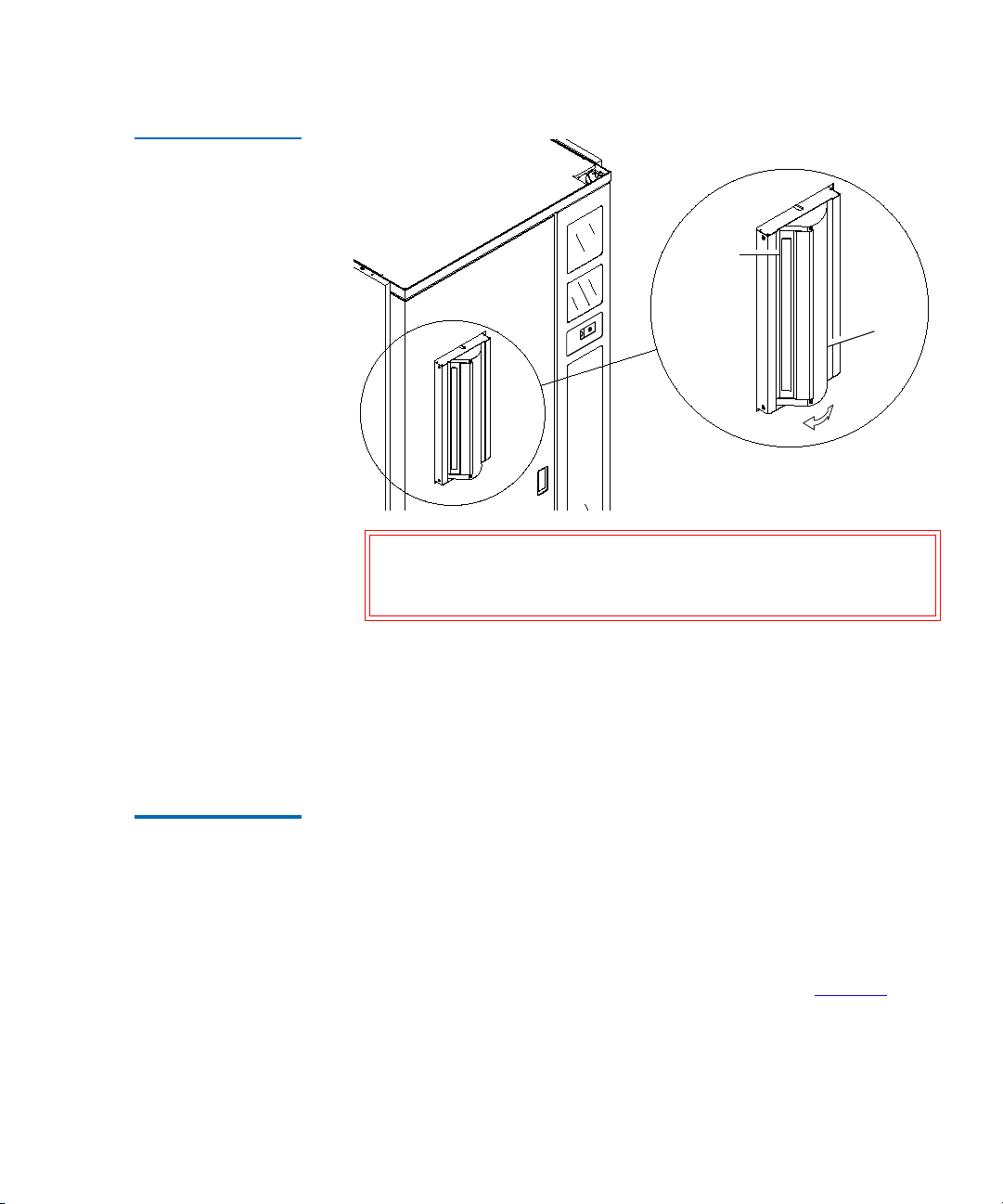
Figure 31 Rotating
the Load Port Drum
Chapter 2 Basic Library Operations
Inserting Tape Cartridges into the Load Port
Load port
finger grip
Load
port
drum
Warning: Take care to keep fingers out of load port openings
when opening or closing the load port door or when
rotating the load port drum.
Inserting LTO Tape Cartridges 2
5 Manually close the load port door by pushing the load port assembly
so that it is flush with the front surface of the library. You will hear a
“click” when it locks into position.
If Auto Load is enabled, the library automatically moves the
cartridges to available bins.
The two load port magazines used when LTO tape drives are present in
the library are stationary and built into the load port. They accommodate
up to 8 LTO or DLT tape cartridges. The magazines employ no loading
mechanism (unlike the DLT removable magazines) .
To insert an LTO cartridge:
1 Simply place the LTO tape cartridge into the bins with the barcodes
facing out and the write-protect switch on the left (see figure 32
Quantum P4000 and P7000 Libraries User’s Guide 57
).
Page 78

Chapter 2 Basic Library Operations
Manually Ejecting a Tape Cartridge
Figure 32 LTO Tape
Cartridge Load Port
Loadport
assembly
Barcode
Write-protect
switch
Stationary
magazine
Manually Ejecting a Tape Cartridge 2
DLT Tape Drives 2 To manually eject a tape cartridge from a DLT tape drives:
1 Open one or both of the library front doors:
a Press the
line.
b Verify that the display state display reads System Off-line and
that the robotics has stopped moving. The off-line state does not
take effect until current commands are completed.
c Take electrostatic discharge precautions as explained in Taking
ESD Precautions on page 32.
d Using the key from the accessories kit, unlock each door.
58 Quantum P4000 and P7000 Libraries User’s Guide
Standby button on the GUI. This places the library off-
Page 79
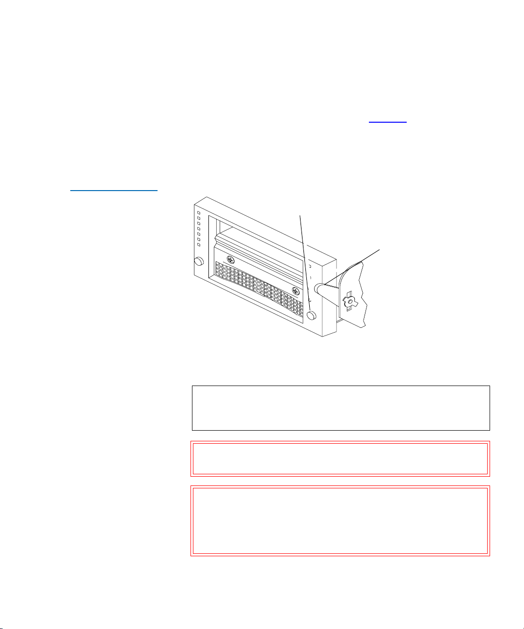
Chapter 2 Basic Library Operations
Manually Ejecting a Tape Cartridge
e Lift each door handle straight up and then turn the handle
counterclockwise to unlatch each door.
f Gently pull on each door handle to open the door.
Figure 33 DLT Tape
Drive Front Bezel
(Example)
2 Press the
When you press
Unload button on the drive (see figure 33).
Unload, the tape cartridge rewinds. This may take
between 10 to 120 seconds. When the rewind process is completed,
the Operate Handle indicator comes on.
Unload button
Insert/release
handle
(shown in up position)
3 When the Operate Handle indicator comes on, raise the insert/
release handle to eject the tape cartridge.
Note: Place your finger approximately 1/4 of an inch in front of
the drive’s cartridge opening to ensure that the cartridge
does not drop when ejected.
Caution: Pause for at least 3 seconds, then grasp the tape
cartridge and slowly pull it half way out of the drive.
Caution: If the tape cartridge leader failed to detach from the
take-up leader, push the tape cartridge all of the way
back into the drive, press down the insert/release
handle, and return to step 2. Otherwise, continue to
step 4.
Quantum P4000 and P7000 Libraries User’s Guide 59
Page 80

Chapter 2 Basic Library Operations
Manually Ejecting a Tape Cartridge
4 Pull the tape cartridge completely out of the drive.
5 Close and lock the library doors.
Quantum SDLT and IBM LTO Tape Drives 2
To manually eject a tape cartridge from Quantum SDLT and LTO tape
drives:
1 Refer to Steps 1a-1f under DLT Tape Drives
.
2 Press the Unload button on the drive. The Unload button works the
same as a soft eject (VCR-style) button.
60 Quantum P4000 and P7000 Libraries User’s Guide
Page 81

Chapter 3
3Operator Commands
This chapter describes the commands found on the Operator screen of the
graphical user interface (GUI). The Operator screen commands initiate
the following actions:
• Opening the Operator Screen
• Configuring the Library*
• Configuring Library Options
• Performing an Inventory
• Moving Cartridges
• Unloading a Drive
• Unloading the Load Port
*
*
*
*
* The library must be off-line to perform these functions.
Caution: Library operator commands are to be used only by
qualified, Quantum-trained personnel. Serious
operational problems and data loss may occur if you do
not understand the consequences of these commands.
Quantum P4000 and P7000 Libraries User’s Guide 61
Page 82

Chapter 3 Operator Commands
Opening the Operator Screen
Opening the Operator Screen 3
To open the Operator screen:
Figure 34 Password
Screen
1 Press the
The GUI displays the password screen (see figure 34
Operator tab.
).
2 Enter the correct operator or service password to gain access to the
Operator Screen (see figure 35).
The default operator password is 1234.
Note: To change passwords, see Changing Passwords on
page 75.
About
System
Off-line
Standby
Load Port
Back Forward
Operator
Enter Password
Enter Password: _
Tapes
Home
Service
1 2
3 4
5 6
O
Stop
62 Quantum P4000 and P7000 Libraries User’s Guide
7 8
9 0
Enter
Page 83
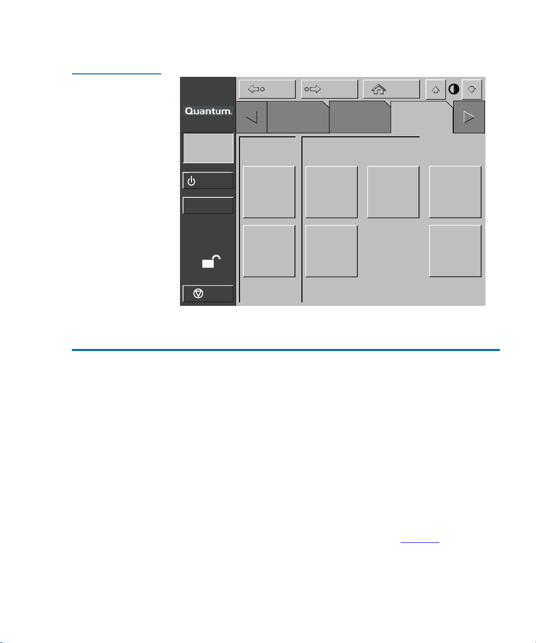
Chapter 3 Operator Commands
Configuring the Library
Figure 35 Operator
Screen
Back Forward
Home
About
Overview Tapes Operator
System
Off-line
Standby
Load Port
Config.
Configure
Library
Configure
Options
Control
Move
Cartridges
Inventory
Tapes
Calibrate
Library
Unload
Drive
Unload
Imp/Exp
O
Stop
Configuring the Library 3
The
Configure Library command allows you to assign the following:
• Library model number
• Number of storage bins
•Number of drives
• Library SCSI ID (not required for Ethernet libraries)
• Tape drive SCSI ID (not required for Ethernet libraries)
To configure any of these attributes use the following procedure.
1 In the
Quantum P4000 and P7000 Libraries User’s Guide 63
Operator screen, press the Configure Library button.
The
Configure: Library screen is displayed (see figure 36).
Page 84

Chapter 3 Operator Commands
Configuring the Library
Figure 36 Configure:
Library Screen
About
Back Forward
Overview Tapes Operator
System
Off-line
Standby
Load Port
O
Stop
2 Press the Configure button.
The GUI displays the
figure 37
Configure: Library
Inquiry: P7000 64xxxxx
Model: 64xxxxx
# Bins: 679
# Drives: 16
Serial Number:
IEEE ID:
Library SCSI ID: 0
Drive 0 SCSI ID: 2
Drive 1 SCSI ID: 3
Drive 2 SCSI ID: 4
Configure: Library Settings screen (see
).
Home
Configure
64 Quantum P4000 and P7000 Libraries User’s Guide
Page 85

Chapter 3 Operator Commands
Configuring the Library
Figure 37 Configure:
Library Settings
Screen
Back Forward
Home
About
Overview Tapes
System
Off-line
Standby
Load Port
Configure: Library Settings
Model:
# Bins:
# Drives:
64xxxxx
679
8
Device: Library
O
Stop
SCSI ID: 0
3 Press the Select button until you highlight the setting you want to
change.
4 Using the arrow buttons, scroll through available values for the
setting.
Operator
Select
Change
SCSI ID Assignment Guidelines 3
5 Press the
Change button to accept the new value.
6 Repeat steps 3 through 5 to make other changes.
7 Press the
Back button to return to the Configure: Library screen.
The options you selected are now part of the library configuration.
When selecting SCSI ID numbers, each SCSI device on the same bus must
have a unique number from 0 to 15. SCSI devices include the library
robotics, the host computer, the library tape drives, internal and external
hard disk drives, and so on.
Quantum P4000 and P7000 Libraries User’s Guide 65
Page 86
Chapter 3 Operator Commands
Configuring Library Opti ons
If you set up the library with multiple SCSI buses, you can assign the
same number to two or more devices, provided each device is on a
different SCSI bus.
Note: Power must be cycled for the new SCSI ID number to become
effective.
Note: SCSI ID assignments are not required for Ethernet based
libraries.
Configuring Library Options 3
The
Configure Options command allows you to set the following:
• Power-On State—determines whether the library is on-line or in
standby mode when powered up. The default setting is On-line.
• AutoClean—allows the library to perform drive cleaning tasks
automatically as needed. The default setting is Disabled.
• Retries—causes the library to automatically retry a failed command
before issuing an error message. The default setting is Enabled.
• Bar Code Labels—turns bar code scanning on or off during inventory.
It should be disabled when the library contains cartridges that are not
labeled. The default setting is Disabled.
• Auto Inventory—causes the library to perform an inventory whenever
the library is powered up. The default setting is Disabled.
• Auto Load—causes the library to automatically move cartridges in the
load port to empty storage bins as soon as the load port door closes.
The default setting is Disable.
• Temp. Detection—enables or disables the over-temperature detection
warning and shutdown features of the library. The default setting is
Enabled.
• Power-On Security—determines the library security level when
powered up. The default setting is User.
66 Quantum P4000 and P7000 Libraries User’s Guide
Page 87

Chapter 3 Operator Commands
Overview Tapes Operator
Back Forward
Home
O
Configure: Options
Execute
Power-On
Retries
Auto
Load
Power-On
Security
Barcode
Labels
Temp.
Detection
P3000
Identity
Auto
Clean
Auto
Inventory
System
Off-line
Standby
Load Port
Stop
Online
New Value:
Current
Value:
About
Configuring Library Options
• P3000 Identity Mode—causes the library to return the same inquiry
string as the P3000 library.
Configuring a Library Option 3
Figure 38 Configure:
Options Screen
To configure a library option:
1 In the
Operator screen, press the Configure Options button.
The GUI displays the
Configure: Options screen (see figure 38).
2 Press the button with the desired option.
3 Using the arrow buttons, scroll through available values for the
selected option.
4 When the New Value box displays the desired value, press the
Execute button to apply the new value.
The Current Value box displays the new value.
5 Repeat steps 2 through 4 to change other configuration options.
6 When you have finished making changes to library options, press the
Back button until you return to the initial Operator screen.
Quantum P4000 and P7000 Libraries User’s Guide 67
Page 88

Chapter 3 Operator Commands
Performing an Inventory
Performing an Inventory 3
The
Inventory Tapes command reads the bar code labels of the cartridges
in the tape drives, fixed storage bins, and the load port bins. All elements
that contain cartridges without labels are marked as full with no label.
1 Press the
The GUI displays a “Command In Progress” screen.
2 Press the
process, otherwise, the process continues until all storage elements
have been inventoried.
Note: The inventory process is also stopped if an error is
Inventory Tapes button in the Operator screen.
Abort button to stop continuous running of the inventory
detected. In this case, the GUI displays an error message.
Moving Cartridges 3
The
Move Cartridges command allows you to move any tape cartridge in
the library to the destination you specify. This destination can be a
storage bin, a tape drive, the load port, or the gripper.
Note: To move a cartridge from a tape drive, issue an Unload Drive
command as explained in Unloading a Drive
.
To move a cartridge:
1 In the
68 Quantum P4000 and P7000 Libraries User’s Guide
Operator screen, press the Move Cartridges button.
The GUI displays the
Source input field active (see figure 39
Control: Move Cartridges screen, with the
).
Page 89

Chapter 3 Operator Commands
Moving Cartridges
Figure 39 Control:
Move Cartridges
Screen
Backspace button:
Use this button to erase a partial
entry - character by character
Back Forward
Home
About
Overview Tapes Operator
System
Off-line
Standby
Load Port
O
Stop
Control: Move Cartridge
Source:
Destination:
Range:
_
Execute
Storage Bin
Drive
Load Port
Gripper
PTM
2 Identify the source element of the cartridge to be moved. Proceed as
follows:
1 2
3 4
5 6
7 8
9 0
Select
a Press the appropriate source element button (
Storage Bin, Tape
Drive, Load Port, or Gripper). When you press an element type, the
Range field (below the Destination field) displays the range of
addresses.
b Using the keypad, enter the address of the source element and
then press the Destination input field. The Source information is
displayed in the Source field and the Destination field becomes
active.
3 Identify the destination for the cartridge:
a Press the appropriate destination element button (
Tape Drive, Load Port, or Gripper).
Storage Bin,
b Using the keypad, enter the address of the destination element
and then press the Execute button. The destination information is
displayed in the Destination text box and the move is initiated.
The GUI displays a
Command In Progress dialog box with an Abort
button.
Quantum P4000 and P7000 Libraries User’s Guide 69
Page 90

Chapter 3 Operator Commands
Overview Tapes Operator
Back Forward
Home
O
Control: Unload Drive
System
Off-line
Standby
Load Port
Stop
Execute
Drive 0
About
Unloading a Drive
The Move Cartridges command continues until completed unless
you press the
Abort button to stop the operation.
Unloading a Drive 3
The
Unload Drive command prepares a tape cartridge to be removed from
a drive by rewinding and ejecting the cartridge. After unloading the
drive, remove the tape cartridge using the
To unload a drive:
Move Cartridges command.
Figure 40 Unload
Drives Screen
1 On the
The GUI displays the
Operator screen, press the Unload Drive button.
Control: Unload Drive screen (see figure 40).
70 Quantum P4000 and P7000 Libraries User’s Guide
2 Use the arrow buttons to highlight the desired drive and then press
Execute.
The GUI displays a
Command In Progress dialog box.
Page 91

Chapter 3 Operator Commands
Unloading the Load Port
The Unload Drive command continues until completed unless you press
the
Abort button to stop the operation.
Unloading the Load Port 3
The
Unload Imp/Exp command moves a tape cartridge from the load port
to an available storage bin. This option must be invoked after inserting a
tape into the load port whenever the library auto load feature is disabled
(see Configuring Library Options
on page 66).
Note: You can also use the
load port. The
Move Cartridge command to unload the
Move Cartridge command is especially useful if
the destination of the move is important. For more information
about the
Move Cartridge command, see Moving Cartridges on
page 68.”
To unload the load port:
1 On the
The GUI displays a
Operator screen, press the Unload Imp/Exp button.
Command In Progress dialog box is displayed.
2 If it becomes necessary to stop the Unload command, press the
button
Note: The inventory process is also stopped if an error is
detected. In this case, the GUI displays an error message.
Abort
Quantum P4000 and P7000 Libraries User’s Guide 71
Page 92

Chapter 3 Operator Commands
Unloading the Load Port
72 Quantum P4000 and P7000 Libraries User’s Guide
Page 93
Chapter 4
4Service Commands
This chapter describes the Service screen commands of the library
graphical user interface (GUI). Topics covered are:
• Opening the Service Screen
• Changing Passwords
• Generating Reports
Warning: Serious operational problems and data loss may occur if
you do not fully understand the consequences of these
commands. The following service tasks are shown here
are for explanation only and should not be carried out by
anyone other than Quantum-trained personnel:
• Testing the Library
• Initializing Non-Volatile Information
Quantum P4000 and P7000 Libraries User’s Guide 73
Page 94

Chapter 4 Service Commands
Opening the Service Screen
Opening the Service Screen 4
Figure 41 Enter
Password Screen
To open the
1 Press the
Service screen:
Service tab.
Note: The Service screen is restricted to individuals with Service-
level access privileges.
2 The GUI displays a password screen (see figure 41
Enter the correct service password to gain access to the
(see figure 43
). The default service password is “5678.”
).
Service screen
Note: For information about changing passwords, see Executing
Either Command on page 83.
Back Forward
Home
About
Service
System
Off-line
Tapes
Enter Password
Operator
1 2
Standby
Load Port
S
Stop
74 Quantum P4000 and P7000 Libraries User’s Guide
Service
Password:
_
3 4
5 6
7 8
9 0
Enter
Page 95
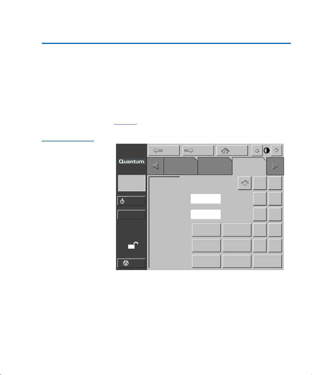
Chapter 4 Service Commands
Changing Passwords
Changing Passwords 4
This command allows you to change the password. Valid passwords
consist of four to eight numeric characters entered using the keypad in
the
Change Password screen.
To change a password:
Figure 42 Service:
Change Password
Screen
1 On the
Service screen, press the Change Password button.
The GUI displays the
figure 42
).
About
System
Off-line
Standby
Load Port
S
Stop
Service: Change Password screen (see
Back Forward
Tapes
Service: Change Password
New Password:
Reenter:
Security Level:
Operator
_
_
Import
Operator
Reset
Passwords
Home
Service
User
Service
Select
1 2
3 4
5 6
7 8
9 0
Enter
2 Press the Security Level button that corresponds to the password you
want to change.
3 Using the keypad, enter a new password and press the
Select button.
Asterisks representing password characters appear in the New
Password field.
4 Reenter the password and press the
Select button.
Asterisks representing the password appear in the Reenter text box.
Quantum P4000 and P7000 Libraries User’s Guide 75
Page 96

Chapter 4 Service Commands
Generating Reports
If You Lose a Password 4
If you lose the Operator, Import Only, or User password, you can replace
it by:
• Opening the
password (see page 84
•Pressing the
This resets all passwords to their default values.
The default values are:
• Service “5678”
• Operator “1234”
• User “2222”
• Import Only “1111”
If you lose the Service password (and cannot access the Change Password
screen), contact the Quantum Customer Support Department for
assistance (see the preface for contact information).
Service screen and following the steps to change the
)
Reset Passwords button on the Change Password screen.
Generating Reports 4
The Service screen enables you to generate on-screen reports about the
following:
• Library operation statistics
• Actuator positions and status
•System test results
• Auto Clean status and tracking information
76 Quantum P4000 and P7000 Libraries User’s Guide
Page 97

Chapter 4 Service Commands
Generating Reports
Generating Any Service Report 4
Figure 43 Service
Screen - Reports
Press the appropriate button in the Service screen.
Within a few seconds, the report is displayed on the screen.
Back Forward
Home
About
System
Off-line
Standby
Load Port
S
Stop
Tapes
Report
Statistics
Actuator
System
Monitor
SysTest
Library
Results
Auto
Clean
Operator
Test Misc.
SysTest
Library
Service
Initialize
Nonvol
Statistics
Initialize
Nonvol
Config
Change
Password
Quantum P4000 and P7000 Libraries User’s Guide 77
Page 98
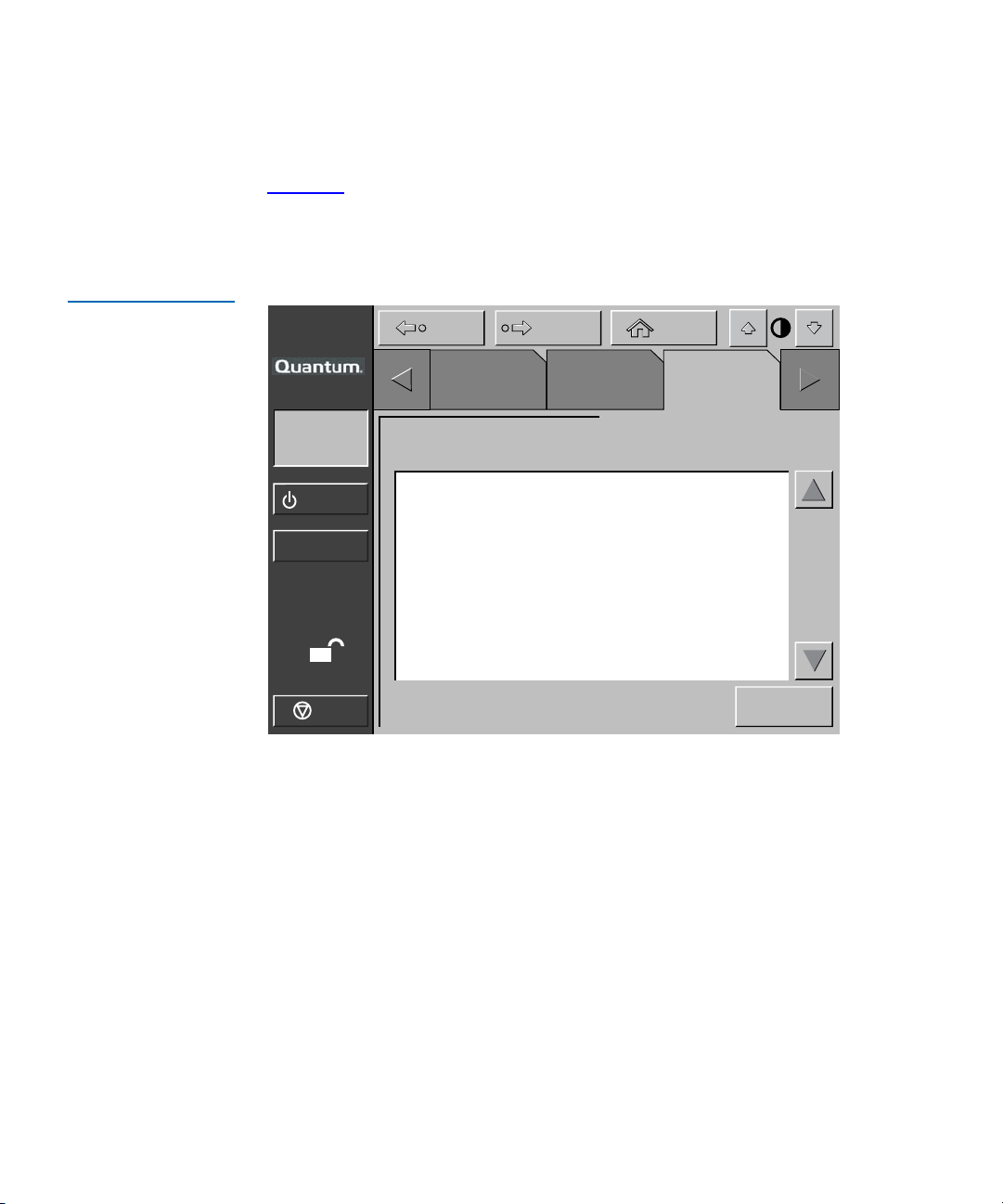
Chapter 4 Service Commands
Generating Reports
Statistics Report 4
Figure 44 Report:
Statistics Screen
Figure 44
Press the
shows a sample Statistics report.
Update button to update the report (otherwise the report will
update periodically).
About
System
Off-line
Standby
Load Port
S
Stop
Report: Statistics
Power On Time (Hr: Min: Sec): 360: 05: 56
Command Time (Hr: Min: Sec): 108: 08: 17
Pick Bin Count: 26501
Place Bin Count: 26435
Pick Drive Count: 11323
Place Drive Count: 10143
Pick Load Port Count: 873
Place Load Port Count: 877
Horizontal Move Count: 268831
Vertical Move Count: 152238
Back Forward
Tapes
Operator
Home
Service
Update
78 Quantum P4000 and P7000 Libraries User’s Guide
Page 99

Chapter 4 Service Commands
Generating Reports
Actuator Report 4
Figure 45 Report:
Actuator Status
Screen
Figure 45
About
System
Off-line
Standby
Load Port
shows a sample Actuator Status report.
Back Forward
Tapes
Operator
Report: Actuator Status
Horizontal Position (in.): 8.752
Vertical Position (in.): 3.126
Extension Position (in.): 0.015
Gripper Position: Closed
Rotary Position: F ront
PTM Position: Inside
S
Stop
Home
Service
Quantum P4000 and P7000 Libraries User’s Guide 79
Page 100

Chapter 4 Service Commands
Generating Reports
SysTest Report 4
Figure 46 Report:
SysTest Library
Results Screen
Figure 46
About
System
Off-line
Standby
Load Port
shows a sample System Test report.
Back Forward
Tapes
Operator
Report: SysTest Library Results
Pick and Place Total Count: 62466
System Test Status: B 80 0B
Total Test Time (Hr:Min:Sec): 61:42:35
Test Type: Random
Avg. Drive to Bin Move Time (Sec): 0.000
Avg. Bin to Drive Move Time (Sec): 0.000
Avg. Bin to Bin Move Time (Sec): 0.000
Longest Move Time (Sec): 0.000
S
Stop
Bad Barcode Reading Count: 0
Place to Drive Count: 2221
Place to Bin Count: 14202
Place to Load Port Count: 2
Home
Service
80 Quantum P4000 and P7000 Libraries User’s Guide
 Loading...