

Page 1

ATL P1000 Series
Tape Library
User’s Guide
6221101-03
Ve r. 3, Rel. 0
Page 2

ATL P1000 Series User’s Guide, 6221101-03, Ver. 3, Rel. 0, September 1999. Pri nted in the USA.
ATL Products, Inc. provides this publication “as is” without warrant y of any k ind , eit her express or implied, including but
not limited to the implied warranties of merchantability or fitness for a particular purpose. ATL Products, Inc. may revise
this publication from time to time without notice.
COPYRIGHT STATEMENT
Copyright 1999 by ATL Products, Inc. All rights reserved.
Your right to copy this manual is limited by copyright law. Making copies or adaptations without prior written
authorization of ATL Products, Inc. is prohibited by law and constitutes a punishable violation of the law.
TRADEMARK STATEMENT
Prism Library Architecture, IntelliGrip, WebAdmin, and WebLibrarian are all trademarks of ATL Products, Inc.
Other trademarks may be mentioned herein which belong to other companies.
FCC STATEMENT
This equipment has been tested a nd foun d to compl y w ith th e limit s fo r a Class A digital device, pursuant to Part 15 of the
FCC Rules. These limits are designed to prov ide r easonable pr otect ion against harmful int erfer ence when the equipment is
operated in a commercial environment. This equipment generates , uses, and can radiate radio fr equency ener gy an d, if not
installed and used in accordance with the instruction manual, may cause harmful interference to radio communications.
Any changes or modifications made to this equipment may void the user's authority to operate this equipment.
Operation of this equipment in a residential area may cause interference in which case the user at his own expense will be
required to take whatever measures may be required to correct the interference.
This device complies with Part 15 of the FCC Rules. Operation is subject to the following c onditions: (1) th is device may not
cause harmful interference, an d (2) this device must accept any interfer ence r eceived, in cluding interfer ence th at may cause
undesired o peration.
INDUSTRY CANADA (DIGITAL APPARATUS)
Interference-Causing Equipment Standard
ICES-003 Issue 2
This Class A digital apparatus meets all requirements of the Canadian Interference-Causing Equipment Regulations.
Cet appareil numérique de la classe A respecte toutes les exigences du Reglément sur le matériel brouilleur du Canada.
CISPR-22 WARNING!
This is a Class A pr oduct. In a domestic en vironment this product may cause radi o in terference in which case the user may
be required to take adequate me asures.
ACHTUNG!
Dieses ist ein Gerät der Funkstörgrenzwertklasse A. In Wohnbereichen können bei Betrieb dieses Gerätes
Rundfunkstörungen auftreten, in welchen Fällen der Benutzer für entspr echende Gegenmassnahmen verantwortlich ist .
A TTENTION!
Ceci est un produit de classe A. Dans un environment domestique, ce produit peut causer des interférences
radioélectriques. Il appartient alors à l'utilisateur de prendre les mesures appropriées.
6207947-06cA 66
Page 3

NOTICE FOR USA AND CANADA ONLY
If shipped to USA, use the UL LISTED power cord specified below for 100-120 V operation. If shipped to Canada, use the
CSA CERTIFIED power cord specified below for 100-120V operation.
Plug Cap Parallel blade with ground pin (NEMA 5-15P configuration)
Cord Socket IEC 320 connector rate d 250V 15A
Cord Type: SJT, three 16 AWG or 18 AWG wires
Length Maximum 15 feet (4.5m)
Rating Minimum 10 A, 125 V
ATTENTION
LIRE LA REMARQUE DANS LE MODE D'EMPLOI.
REMARQUE
CETTE REMARQUE NE CONCERNE QUE LES ÉTATS-UNIS ET LE CANADA.
En cas d'envoi aux États-Unis, utiliser le cordon d'alimentation CERTIFIÉ UL et convenant pour 100-120 V.
En cas d'envoi au Canada, utiliser le cordon d'alimentation CERTIFIÉ CSA et convenant pour 100-120 V.
Fiche Broches parallèles avec une broche de mise à la terre (configuration NEMA 5-15P)
Cordon Type: SJT, trifilaire 16 AWG ou 18 AWG
Longeur Maximum 15 pieds (4.5m)
Capacité Minimum 10 A, 125 V
BATTERY STATEMENT
Caution
The Dallas Semiconductor DS1230AB-200 component on th e ro botic contr oller bo ar d inside t his pr oduct conta ins a lith ium
battery. Lithium is a hazardous material that must be disposed of in accordance with local, state, and federal law.
Forsigtig
Båndbiblioteket indeholder et lithiumbatteri. Dallas Semiconductor DS1230AB-200 på robotkontroltavlen indeholder et
lithiumbatteri. Lithium kan anses for at være et sundhedsfarligt materiale. Kassér dette batteri i overensstemmelse med
lokale og nationale lovbestemmelser.
Huomautus
Nauhakirjastossa on litiumparisto. Robottiohjainkortin Dallas Semiconductor DS1230AB-200-puolijohteessa on
litiumparisto. Litium voidaan luokitella vaaralliseksi aineeksi. Pariston hävittämisessä on noudatettava viranomaisten
antamia ohjeit a ja määräyksiä.
Attention
La bibliothèque de bande contient une pile au lithium. Le Dallas Semiconductor DS1230AB-200 sur la carte robotic
contrôleur contient une pile au lithium. Le lithium peut être considéré comme matériau dangereux. Jeter cette pile
conformément aux lois locales, d’état et fédérales.
Page 4

Achtung!
Die Bandbibliothek enthält eine Lithiumbatterie. Der Halbleiter Dallas Semiconductor DS1230AB-200 auf dem RoboterController enthält ein e Lithiumb at terie. Lithium gilt als Schadstoff. Bei der Entsorgung dieser Batterie alle entsprechenden
kommunalen, staatlichen und bundesweiten Vorschriften beachten!
Attenzione
La libreria a nastro magnetico contiene una batteria al litio. Il semiconduttore Dallas Semiconductor DS1230AB-200 sulla
scheda controller robotic contiene una batteria al litio. Il litio può essere considerato un materiale pericoloso. Eliminare
queste batterie in conformità alle normative locali e statali vigenti.
Forsiktig
Kassettbiblioteket inneholder et litiumbatteri. Enheten Dallas Semiconductor DS1230AB-200 på robotkontrollkortet
inneholder et litiumbatteri. Litium kan anses som et farlig materiale. Batteriet skal kastes i henhold til lokal og nasjonal
lovgivning.
Precaución
La biblioteca de cintas contiene una pila de litio. El semiconductor Dallas Semiconductor DS1230AB-200 en el tablero
controlador robotic contiene una pila de litio. El litio puede considerarse como un material peligroso. Deseche esta pila de
acuerdo con las leyes municipales, estatales y federales.
Varning!
Magnetbandsbibliot eket inn ehå ller ett lit iumb atter i. Dal las Sem icondu ctor D S1230 AB-20 0 på r ob otsty rkor tet inn ehå ller ett
litiumbatteri. Litium kan anses vara ett farligt material. Kassera detta batteri i enlighet med lokala och statliga lagar och
förordningar .
Page 5

Contents
Contents
Preface
Chapter 1
Library Description......................................................................................1
Configuration Options..................................................................................3
Library Elements ...........................................................................................5
Robotics Operation...................................................................... ......... .........7
Operator-Accessible Components..............................................................8
Front Panel...............................................................................................8
Load and Bulk Packs............................................................................10
Back Panel..............................................................................................11
Tape Drives............................................................................................12
0
Chapter 2
Installing the P1000 Library.....................................................................13
Site Requirements........................................................................................14
Floor Space.............................................................................................14
Floor Clearance .....................................................................................15
Floor Strength and Inclination............................................................15
Overhead Clearance.............................................................................15
Power and Grounding .........................................................................15
Environmental Requirements.............................................................16
Unpacking the P1000 ................................................ ......... .........................17
Unloading Space Requirements .........................................................17
Uncrating the Library...........................................................................18
Checking the Contents.........................................................................20
Installing the Slide Assembly in the Rack.........................................21
Removing the Library from the Pallet...............................................21
Removing the Internal Packing Materials.........................................27
Preparing and Inserting Tape Cartridges................................................30
Labeling a Tape Cartridge...................................................................30
Setting the Write-protect Switch.........................................................32
Placing Tape Cartridges in the Fixed Storage Bins..........................32
Placing Tape Cartridges in the Load and Bulk Packs .....................34
Connecting Host Computers.....................................................................35
SCSI Cabling Guidelines......................................................................35
vATL P1000 Series User’s Guide
Page 6

Contents
SCSI Cabling Examples.......................................................................35
Turning On the Library..............................................................................39
Configuring and Testing the Library.......................................................40
Chapter 3
Basic Operations ........................................................................................41
Using the GUI..............................................................................................42
GUI Components.................................................................................. 42
GUI Screens...........................................................................................45
Obtaining Library Status............................................................................46
Overview Screen................................................................................... 46
Tapes Screen..........................................................................................48
Changing the GUI Security Level.............................................................49
Securing the GUI .............................................. ......... ......... ..................49
Performing Manual Operations................................................................51
Turning On the Library.......................................................................51
Placing the Library On-line.................................................................51
Placing the Library Off-line ................................................................52
Turning Off the Library.......................................................................52
Inserting Tape Cartridges ...................................................................52
Opening the Library Doors.................................................................54
Manually Ejecting a Cartridge............................................................55
Chapter 4
Operator Commands.................................................................................57
Accessing the Operator Screen .................................................................58
Configuring the Library.............................................................................60
Configuring Library Options....................................................................62
Moving a Cartridge ....................................................................................64
Performing an Inventory ...........................................................................66
Calibrating the Library............................................................................... 67
Exercising the Library ................................................................................69
Unloading a Drive ......................................................................................70
Unloading the Load Port ...........................................................................71
Chapter 5
Service Commands....................................................................................73
Accessing the Service Screen.....................................................................74
Generating Reports.....................................................................................76
Testing the Library......................................................................................79
Performing a System Test ...................................................................79
Performing a Service Calibration.......................................................80
vi ATL P1000 Series User’s Guide
Page 7

Contents
Initializing Nonvolatile Information........................................................81
Changing Passwords ..................................................................................83
Chapter 6
Troubleshooting.........................................................................................85
Start-up Problems........................................................................................86
GUI Problems...............................................................................................87
Robotics Problems....................................................................... ......... .......88
Operating Problems....................................................................................90
Tape Drive Problems ......................................................... ......... ................92
Appendix A
Specifications....................................................................................... .......93
Appendix B
Installing the Slide Assembly in the Rack............................................97
Verifying the Rack Requirements.............................................................98
Rack Current Rating Consideration...................................................98
Grounding..............................................................................................98
Temperature ..........................................................................................98
Determining the Mounting Position.........................................................99
Installing the Slide Assembly in the Rack..............................................101
Adjusting the Slide Assembly .................................................................103
Adjusting the Slide Assembly on the Mounting Brackets............103
Adjusting the Slide Assembly Tray on the Slide Rails..................105
Glossary
Index
ATL P1000 Series User’s Guide vii
Page 8

Contents
viii ATL P1000 Series User’s Guide
Page 9

Figures
Figures
Figure 1 P1000 Front View, Stand-alone Library..................................1
Figure 2 P1000 Front View, Rack-mount Library.................................2
Figure 3 P1000 Library, Back View.........................................................4
Figure 4 Library Elements............................................. ......... ..................6
Figure 5 P1000 Front Panel ......................................................................8
Figure 6 GUI: Initial Screen......................................................................9
Figure 7 Load and Bulk Packs...............................................................10
Figure 8 Back Panel, Stand-alone Library............................................11
0
Figure 9 Floor Space Requirements, Stand-alone Library.................14
Figure 10 Floor Space Requirements, Rack-mount Library................15
Figure 11 AC Power Receptacle.............................................. ......... .......16
Figure 12 Unloading Space Requirements, Stand-alone Library.......18
Figure 13 Uncrating the Stand-alone Library........................................19
Figure 14 Uncrating the Rack-mount Library.......................................20
Figure 15 Removing the Foam Supports, Stand-alone Library..........22
Figure 16 Removing the Stand-alone Library from the Pallet............22
Figure 17 Lifting the Rack-mount Library from the Pallet..................24
Figure 18 Placing the Library on the Slide Assembly Tray.................25
Figure 19 Locking the Slide Tray in the Rack........................................26
Figure 20 Removing the Load and Bulk Packs.....................................28
Figure 21 Removing the Shipping Restraint .........................................29
Figure 22 Bar Code Label Dimensions...................................................31
Figure 23 Inserting a Bar Code Label .....................................................31
Figure 24 Setting the Write-protect Switch............................................32
Figure 25 Correct Tape Cartridge Orientation......................................33
Figure 26 Single-Host SCSI Configuration............................................36
Figure 27 Typical Two-Host SCSI Configuration.................................37
Figure 28 Five-Host SCSI Configuration ...............................................38
ixATL P1000 Series User’s Guide
Page 10

Figures
Figure 29 GUI: Initial Screen...................................................................42
Figure 30 Navigating through the GUI Screens...................................44
Figure 31 GUI Screens.............................................................................. 45
Figure 32 Overview Screen......................................................................46
Figure 33 Overview Screen with Expanded Tape Drive Status......... 47
Figure 34 Tapes Screen.............................................................................48
Figure 35 Password Screen......................................................................50
Figure 36 Inserting a Tape Cartridge.....................................................54
Figure 37 Enter Password Screen...........................................................58
Figure 38 Operator Screen.......................................................................59
Figure 39 Configure: Library Screen......................................................60
Figure 40 Configure: Library Settings Screen.......................................61
Figure 41 Configure: Options Screen.....................................................63
Figure 42 Control: Move Cartridge Screen ...........................................64
Figure 43 Calibrate Library Screen.........................................................67
Figure 44 Control: Unload Drive Screen ...............................................70
Figure 45 Enter Password Screen...........................................................74
Figure 46 Service Screen ..........................................................................75
Figure 47 Report: Statistics Screen.......................................................... 76
Figure 48 Report: Actuator Status Screen..............................................77
Figure 49 Report: SysTest Library Results Screen................................77
Figure 50 Report: AutoClean Status Screen..........................................78
Figure 51 Test: SysTest Library Screen..................................................79
Figure 52 Confirmation Screen...............................................................82
Figure 53 Service: Change Password Screen ........................................83
Figure 54 Positioning the Slide Assembly.............................................99
Figure 55 Installing the Slide Assembly in the Rack .........................102
Figure 56 Loosening the Outer Nuts....................................................103
Figure 57 Slide Assembly Tray, Fully Extended................................105
Figure 58 Loosening the Inner Nuts ....................................................106
x ATL P1000 Series User’s Guide
Page 11

Tables
Tables
Table 1 Related Documentation........................................................xiv
Table 2 Bar Code Label Specifications................................................30
Table 3 Sample Library Configuration ...............................................40
Table 4 Vertical Bar Buttons and Indicators......................................43
Table 5 Horizontal Bar Buttons...........................................................44
Table 6 GUI Screens ..............................................................................45
Table 7 GUI Security Levels.................................................................49
Table 8 Available Settings, Configure: Options Screen...................62
0
Table 9 Start-up Problems....................................................................86
Table 10 GUI Problems...........................................................................87
Table 11 Robotics Problems...................................................................88
Table 12 Operating Problems ................................................................90
Table 13 Tape Drive Problems...............................................................92
Table 14 Physical Characteristics ..........................................................93
Table 15 Performance Characteristics...................................................93
Table 16 Environmental Specifications ................................................94
xi ATL P1000 Series User’s Guide
Page 12

Tables
xii ATL P1000 Series User’s Guide
Page 13

Preface
Preface
0
Audience
Purpose
Document
Organization
0
0
This guide was written for operators of the P1000 library.
This guide provides procedures for unpacking, installing, operating,
and troubleshooting the basic P1000 library with a standard SCSI host
interface.
The optional Fibre Channel capabiliti es are detaile d in a separate series
of documents (see “Related Documents” on page xiv).
This guide is organized as follows:
0
• Chapter 1, “Library Description,” provides an overview of the
P1000 components and operation.
• Chapter 2, “Installing the P1000 Library,” explains how to unpack
and install the P1000.
• Chapter 3, “Basic Operations,” introduces the P1000’s touc h scr een
graphical user interface (GUI) and explains how to obtain library
status, change the GUI security level, and perform several manual
operations such as turning the library on and off and i nserting tape
cartridges.
• Chapter 4, “Operator Commands,” describes each of the
commands on the Operator screen of the GUI.
• Chapter 5, “Service Commands,” describes each of the commands
on the Service screen of the GUI.
• Chapter 6, “Troubleshooting,” discusses typical P1000 operating
problems and provides probable solutions.
• Appendix A, “Specifications,” pr ovides t he physic al, performance ,
and environmental characteristics of the P1000.
• Appendix B, “Installing the Slide Assembly in the Rack,” explains
how to install the slide assembly in the rack (for rack-mount units
only).
This guide concludes with a glossary and an index.
xiiiATL P1000 Series User’s Guide
Page 14

Preface
Notational
Conventions
This manual uses the following conventions:
0
0
Caution:
Cautions indicate potential hazards to equipment and are
included to prevent damage to equipment.
Note:
Notes emphasize important information related to the main topic.
Warning:
Warnings indicate potential hazards to personal safety and
are included to prevent injury.
This manual uses the following:
• Right side of the library — Refers to the right side as you face the
component being described.
• Left side of the library — Refers to the left side as you face the
component being described.
Related Documents
Table 1 Related
Documentation
0
Note:
This section lists documents related to the ATL P1000 library.
ATL P1000 Documentation
Table 1 lists other manuals associated with the P1000 library.
Document
Number Title Description
6221100
6331101
A TL P100 0 Series Library
Unpacking Instructi on s
A TL P ris m FC210 Ro uter
Addendum
This document explains how to
unpack the P1000 library.
This document provides
operating and troubleshooting
procedures that are specific to
P1000 libraries with the Prism
FC210 Router.
For information regardi ng your tape drive, see the appropriate
manual.
0
product
xiv ATL P1000 Series User’s Guide
Page 15

Preface
Contacts
SCSI-2 Specification
0
The SCSI-2 communications specification is the proposed American
National Standard for information systems, dated March 9, 1990.
Copies may be obtained from:
Global Engineering Documents
15 Inverness Way, East
Eaglewood, CO 80112
(800) 854-7179 or (303) 397-2740
0
This section provides contact information for ATL Products.
ATL Products Corporate Headquarters
0
To order documentation for the ATL P1000, contact:
ATL Products, Inc.
101 Innovation Drive
Irvine, CA 92612
(949) 856-7800
(800) 284-5101
Note:
When placing an order for a document, please specify its part number.
Technical Publications
To comment on existing documentation send e-mail to:
atl-docs@atlp.com
Internet
Visit ATL’s home page at:
http://www.atlp.com
Professional Services
The ATL Products Professional Services Department provides a
24-hour help desk that can be reached at:
voice: (949) 477-7924 or (800) 284-5101
fax: (949) 477-7940
e-mail: helpdesk@atlp.com
0
0
0
ATL P1000 Series User’s Guide xv
Page 16

Preface
xvi ATL P1000 Series User’s Guide
Page 17
Chapter 1
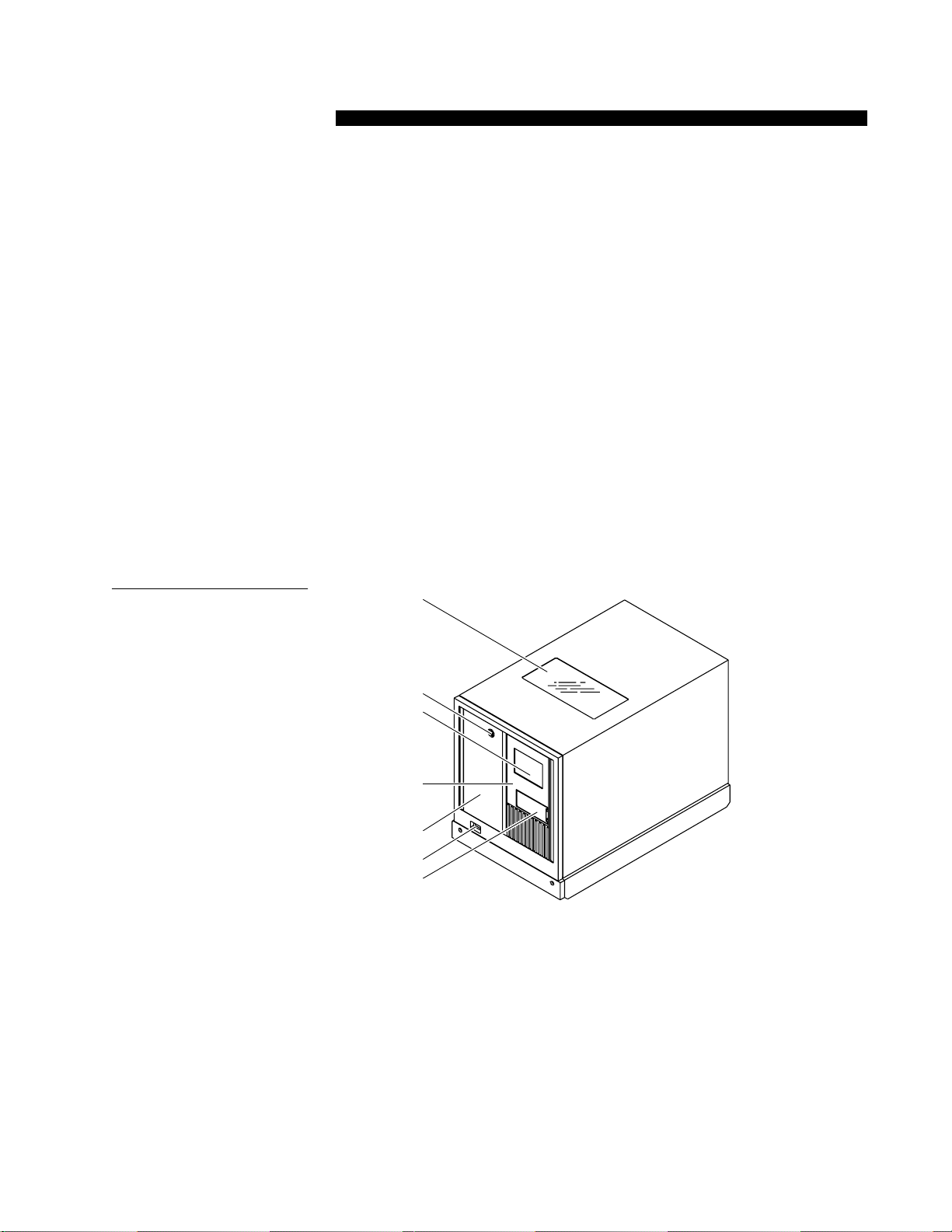
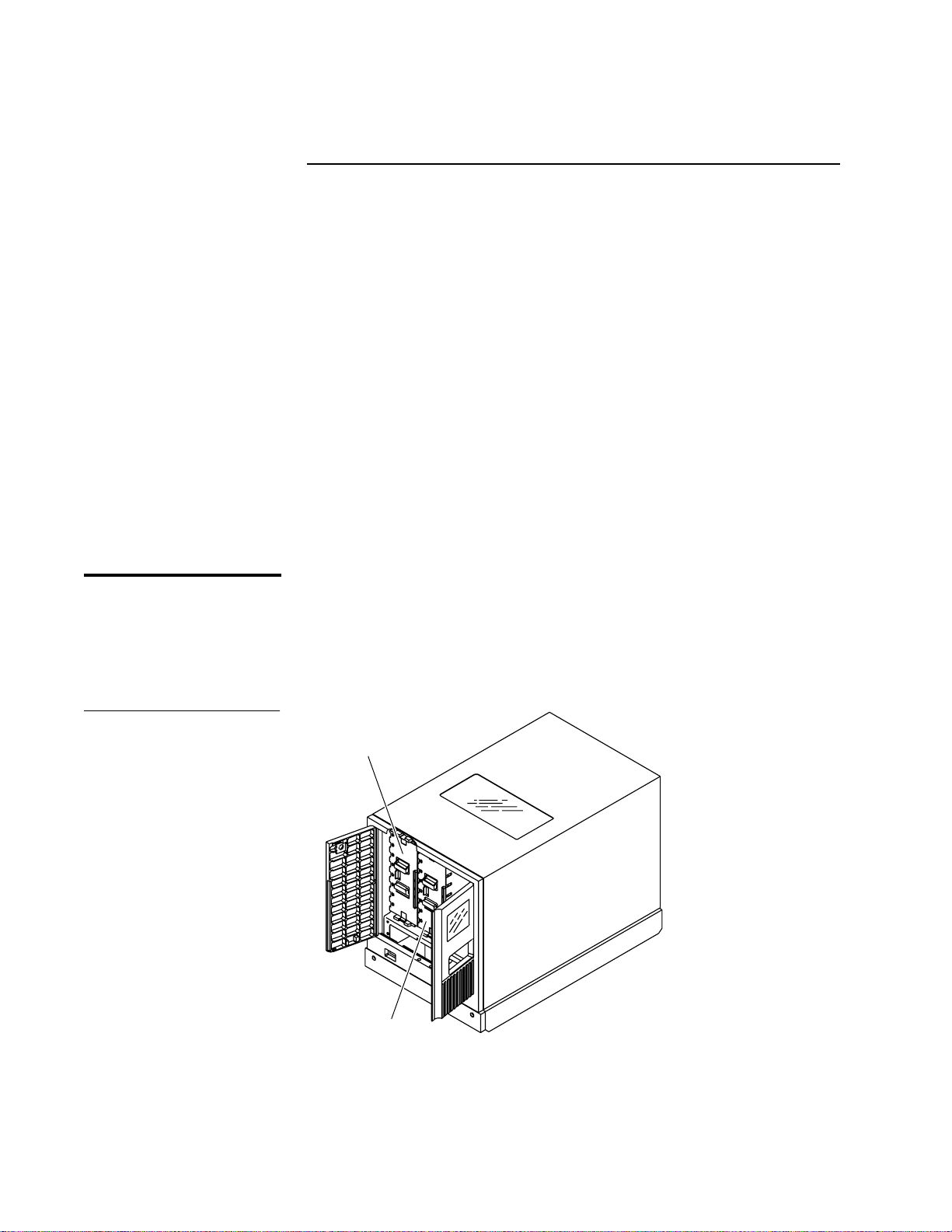
Key lock
Bulk pack door
Power switch
Window
Touch screen
Load port
Load pack door
graphical user
interface (GUI)
Chapter 1 Library Description
Figure 1 P1000 Front
View, Stand-alone Library
Note:
Library Description
The ATL P1000 is an automated tape library system. When fully
configured, the P1000 consists of four tape drives and 30 cartridges.
The maximum storage capacity of the P1000 is 1050 GB (up to 2100 GB
compressed), based on 30 cartridges at 35 GB each (up to 70 GB
compressed).
The P1000 library is shipped in either a stand-alone (see figure 1) or
rack-mount configuration (see figure 2). The stand-alone P1000 is set
on casters. The rack-mount P1000 comes with a slide tray assembl y for
installation in a rack.
A rack is not provided with the rack-mount P1000; it must be obtained
separately.
1
1ATL P1000 Series User’s Guide
Page 18

Chapter 1 Library Description
Figure 2 P1000 Front
View, Rack-mount Library
Rack (not included)
Key lock
GUI
Bulk pack door
Load pack door
Power switch
Load port
2 ATL P1000 Series User’s Guide
Page 19

Chapter 1 Library Description
Configuration Options
Configuration Options
As shown in figure 1 and figure 2, the P1000 library is available in
stand-alone and rack-mount configurations. Other library options
include:
•
the number of tape drives
The P1000 holds one to four tape drives.
•
high-density or low-density tape configuration
The high-density configuration consists of up to 30 tape cartridges:
9 in the back storage bins, 5 in the front storage bins, 8 in the load
pack, and 8 in the bulk pack.
The low-density configuration consists of 16 tape cartridges
housed in the load pack and bulk pack. All fixed storage bins are
removed from the low-density library.
•
single-ended or differential SCSI communication module
•
optical or copper-based Fibre Channel communication module
The P1000 can be supplied with (or upgraded to) various Fibre
Channel host interfaces, including a data router capability that
convert Fibre Channel to SCSI within the library. This o ption is
described in the
ATL Prism FC210 Router Addendum
(PN 6331101).
1
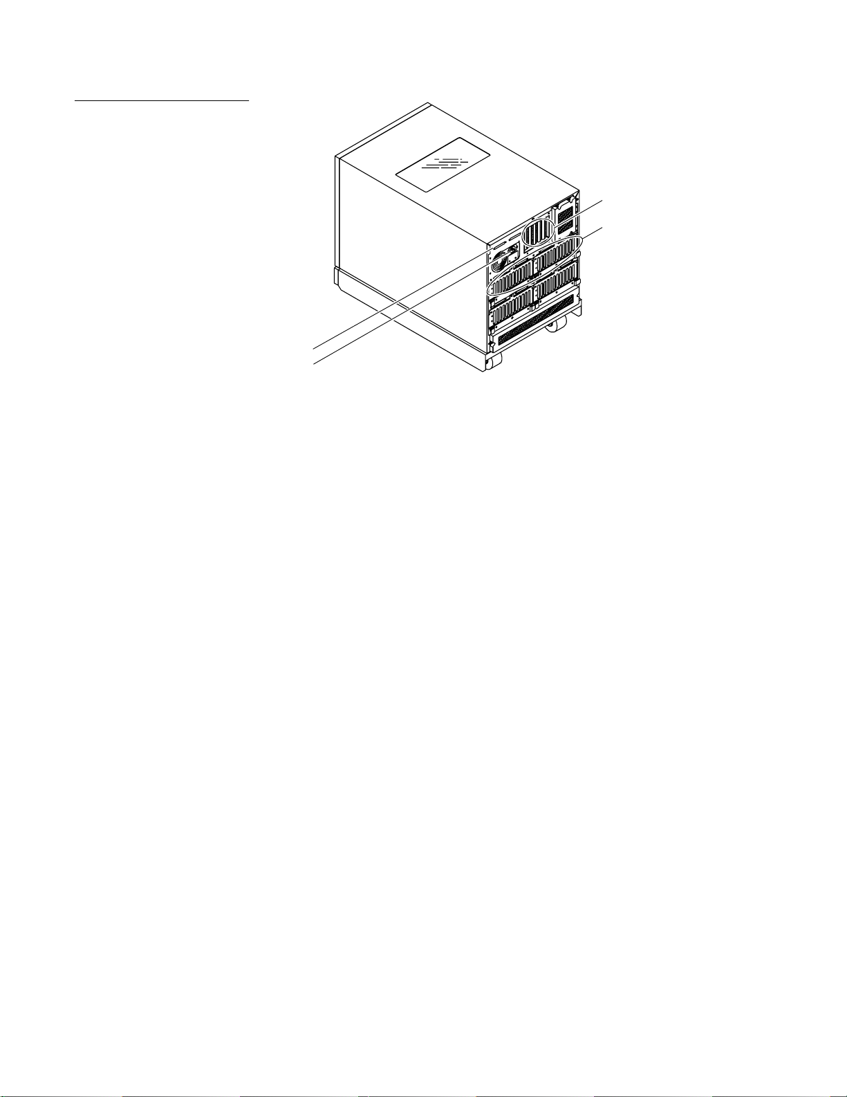
•
multiple SCSI bus capability
The P1000 supports one to five host computers, each on a separate
SCSI bus. The library is controlled by these host computers via a
SCSI communications link and the SCSI-2 medium changer
command set. The host computer SCSI interface port, the RS-232
port for diagnostics, and the power connectors are located on the
back panel (see figure 3 on page 4).
As you unpack and install the P1000, verify that the library is
configured with the options you require.
ATL P1000 Series User’s Guide 3
Page 20
Chapter 1 Library Description
Configuration Options
Figure 3 P1000 Library,
Back View
Host port, DIAG port, and
library printed circuit boards
Tape drive SCSI connectors
Bus connector
Power connector
4 ATL P1000 Series User’s Guide
Page 21

Chapter 1 Library Description
Library Elements
Library Elements
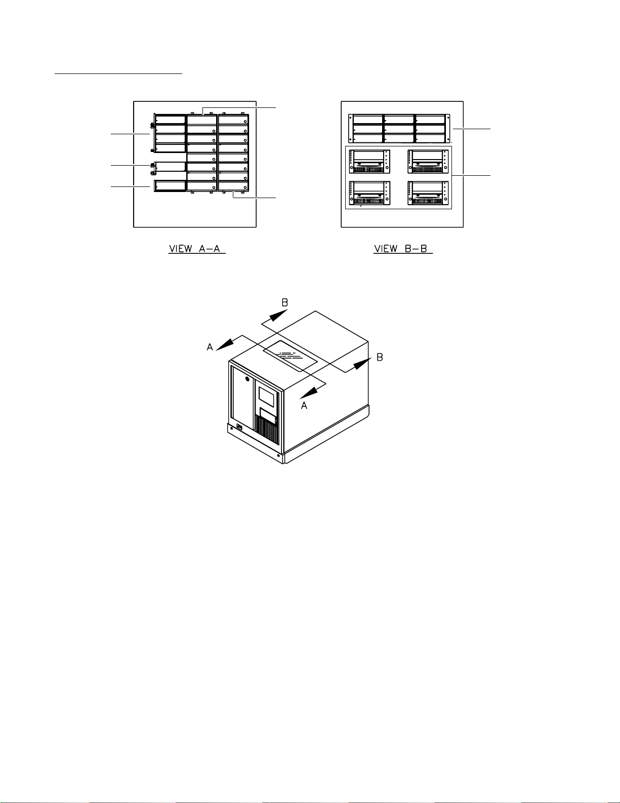
The P1000 has the following elements (see figure 4 on page 6):
•
storage bins
•
nine-pack fixed storage array (bins 0 to 8) (in high-density
configuration only)
•
four-pack fixed storage array (bins 9 to 12) (in high-density
configuration only)
•
one-pack fixed storage array (bin 13) (in high-density
configuration only)
•
bulk pack (bins 14 to 21)
•
load pack (bins 22 to 29)
Note:
•
In the low-density configuration, the P1000 stores tapes in the
load and bulk packs only. All fixed bins are removed from the
library.
import export elements
1
•
load port (load 0)
•
load pack (when configured for import or export operation,
these bins are numbered Load 1 to Load 8)
•
up to 4 tape drives (drives 0, 1, 2, and 3)
ATL P1000 Series User’s Guide 5
Page 22
Chapter 1 Library Description
Library Elements
Figure 4 Library Elements
Four-pack
3
array
Load port
One-pack
3
array
Bin 9
Bin 10
Bin 11
Bin 12
Load 0
Bin 13
Bin 14
Bin 15
Bin 16
Bin 17
Bin 18
Bin 19
Bin 20
Bin 21
Bin 22
Bin 23
Bin 24
Bin 25
Bin 26
Bin 27
Bin 28
Bin 29
Bulk pack
Load pack
Bin 0
Bin 1
Bin 2
Drive 0
Drive 2
1
Bin 3
Bin 4
Bin 5
Bin 6
Bin 7
Bin 8
Drive 1
Drive 3
1
When configured as an
Nine-pack
3
array
Tape
2
drives
import/export device, load
pack bins are numbered
“Load 1” to “Load 8.”
2
When fewer than four
drives are present in the
P1000, the drives occupy
consecutive bays, starting
with drive bay 0.
3
These bins are present
only in the high-density
configuration.
6 ATL P1000 Series User’s Guide
Page 23

Chapter 1 Library Description
Robotics Operation
Robotics Operation
Library robotics consist of the following components:
•
gripper mechanism/bar code reader
•
vertical actuator
•
horizontal actuator
•
extension ac tuator
The vertical and horizontal actuators move the gripper into position to
pick and place tape cartridges. The horizontal actuator also rotates the
gripper 180 degrees, allowing the gripper to pass cartridges between
the front storage bins and the back storage bins or tape drives. The
extension actuator extends the gripper forward to make contact with
the desired cartridge and then retracts the gripper to remove the
cartridge from a bin or drive.
The gripper includes bar code scanners which can read standard sixcharacter, 3 of 9 bar code labels. These scanners are used to maintain
an inventory of the tape cartridges within the P1000. For example, an
inventory occurs automatically when you turn on the library or close
the bulk pack door. You may also initiate an inventory manually from
the host computer.
1
Note:
Although the P1000 does not require tape cartridges to have bar code
labels, properly labeled tape cartridges and full storage bins speed the
inventory process.
The automatic inventory feature can be disabled using the touch
screen GUI (see chapter 4). This is useful for systems with unlabeled
tape cartridges or partially filled storage bins.
Caution:
The LED scanner is classified as a Class 1 LED light
emitting device by IEC 825. The wavelength is 850 nm
(invisible ultraviolet).
ATL P1000 Series User’s Guide 7
Page 24
Chapter 1 Library Description
Operator-Accessible Components
Front Panel
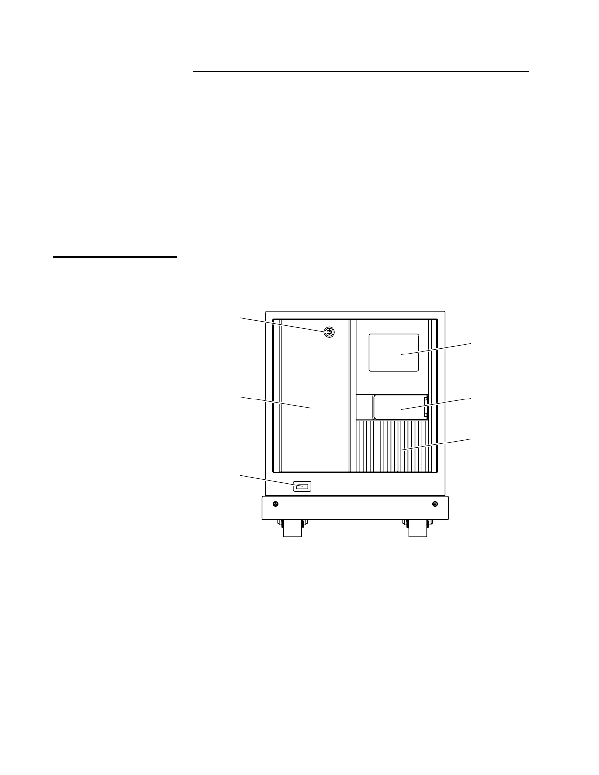
Figure 5 P1000 Front
Panel
Operator-Accessible Components
1
The following P1000 components are operator-accessible:
•
front panel
•
load and bulk packs
•
back panel
•
tape drives
The following sections describe each of these components.
1
The front panel consists of the GUI, the front doors and key lock, the
power switch, and the load port (see figure 5).
Key lock
GUI
Load pack door
Power switch
Load port
Bulk pack door
GUI
The GUI (see figure 6) displays touch screen menus that allow you to
determine library status, configure the library, and perform certain
diagnostic functions.
1
8 ATL P1000 Series User’s Guide
Page 25

Figure 6 GUI: Initial
Horizontal bar
Vertical bar
Main display
area
Screen
Chapter 1 Library Description
Operator-Accessible C om pon ent s
Back Forward
ATL
PRODUCTS
System
Off-line
Standby
Load Port
Load Pack
U
Stop
The GUI screen consists of:
•
a horizontal bar (at the top of the screen)
•
a vertical bar (at the left side of the screen)
•
a main display area
The main display area contains a series of screens with status,
configuration, diagnostic, and operating controls. The horizontal and
vertical bars remain the same while the content of the main display
area changes.
Overview Tapes Operator
ATL
ATL
PRODUCTS
P1000
Home
For further information about the GUI, see chapters 3 and 4.
Front Doors
The front doors provide access to the load packs and the tape drives.
They allow you to insert and remove tape cartridges and manually
perform tape drive functions.
Warning:
Before opening the front doors of the P1000, make sure the
library is in standby mode and the robotics have come to a
complete stop. Failure to do so may result in personal
injury or damage to the P1000.
1
ATL P1000 Series User’s Guide 9
Page 26
Chapter 1 Library Description
Operator-Accessible Components
The front doors lock to prevent unauthorized access to the P1000. To
unlock and open the doors:
Procedure
1
If the library is on-line, press the Standby button on the GUI.
The system status indicator above the Standby button changes to
indicate that the library is in Standby mode.
2
Use the key to unlock the load pack door.
3
Press the Load Pack button on the GUI.
This prepares the library for load pack removal. Always press the
Load Pack button before opening the front door to access the load
pack.
4
Open the left door and then open the right door.
Load and Bulk Packs
Figure 7 Load and Bulk
Packs
Load Port
1
The load port enables you to insert a single tape cartridge into the
P1000. To open the load port, press the Load Port button on the GUI.
1
The load and bulk packs are eight-cartridge removable magazines that
attach to the front storage bin frame (see figure 7). Use these packs to
add or remove multiple tape cartridges.
The load pack can be configured as an additional load port.
Load pack
Bulk pack
To install or remove load or bulk packs, see chapters 2 and 3.
10 ATL P1000 Series User’s Guide
Page 27
Chapter 1 Library Description
Operator-Accessible C om pon ent s
Back Panel
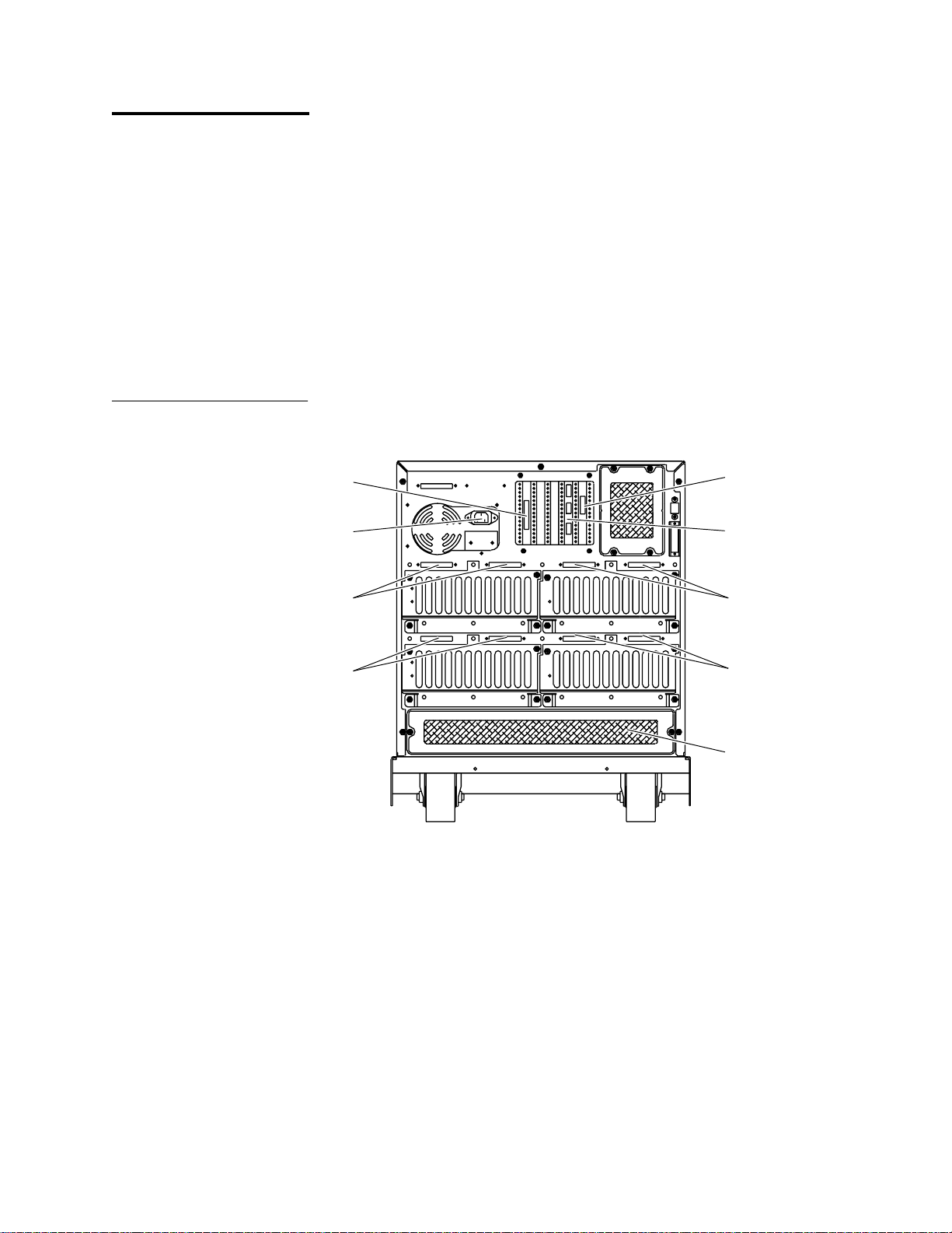
Figure 8 Back Panel,
Stand-alone Library
1
The back panel of the P1000 (see figure 8) has the following
components:
•
•
•
•
•
These components provide the P1000 with power and communication
links to external systems.
Host SCSI port
Power connector
SCSI ports
RS-232C diagnostic (DIAG) port
power connector
drive access (hot swap)
air filters
Actuator driver card
Robotics controller card/
DIAG port
Drive 1 SCSI ports
Drive 3 SCSI ports
Drive 0 SCSI ports
Drive 2 SCSI ports
Air filter
ATL P1000 Series User’s Guide 11
Page 28

Chapter 1 Library Description
Operator-Accessible Components
Tape Drives
1
The P1000 holds up to four tape drives. When fewer than four tape
drives are installed, the tape drives must occupy consecutive drive
bays, beginning with drive bay 0 (see figure 4 on page 6).
12 ATL P1000 Series User’s Guide
Page 29

Chapter 2
Chapter 2 Installing the P1000 Library
Installing the P1000 Library
This chapter explains how to install the stand-alone and rack-mount
configurations of the P1000 library. Installation consists of the
following tasks:
•
verifying that the installation site meets the site requirements
•
unpacking and positioning the library
•
preparing and inserting tape cartridges
•
connecting host computer(s) to the library
•
turning on the library
•
configuring and testing the library
2
13ATL P1000 Series User’s Guide
Page 30
Chapter 2 Installing the P1000 Library
Site Requirements
Floor Space
Figure 9 Floor Space
Requirements,
Stand-alone Library
Site Requirements
2
When selecting an installation site for the P1000 library, consider the
following requirements:
•
floor space
•
floor clearance
•
overhead clearance
•
floor strength and inclination
•
power and grounding
•
environmental factors
2
Figure 9 shows the floor space requirements of the stand-alone P1000.
17.5 in.
(45 cm)
24 in. (61 cm)
29.5 in. (75 cm)
Library FrontBack
54 in. (137.2 cm)
14 ATL P1000 Series User’s Guide
Page 31

Figure 10 Floor Space
Requirements,
Rack-mount Library
Chapter 2 Installing the P1000 Library
Site Requirements
Figure 10 shows the floor space requirements for the rack-mount
P1000.
24 in.
(61 cm)
each side
24 in. (61 cm)
Front
17.5 in.
(45 cm)
Floor Clearance
Floor Strength and Inclination
Library
Back
2
The stand-alone P1000 has a floor clearance of 0.75 in. (1.9 cm). Place
19-inch rack
(extended
from rack)
30 in. (76.2 cm)
24 in.
(61 cm)
the library on a level, uncarpeted floor free of defects.
The floor at the installation site must be rated at 250 lb/ft2
2
(1221 kg/m
2
). This is sufficient to support a fully loaded P1000 on the
floor or in a rack.
The floor at the installation site must be level to within 0. 25 in (6.4 mm)
over a 6 ft by 6 ft (1.8 m by 1.8 m) area.
Overhead Clearance
Power and Grounding
2
To remove the P1000 enclosure, there must be a minimum cl earance of
24 in. (61 cm) above the library. When combined with the height of the
library (21 in./53 cm), this is a total of 45 in. (114.5 cm) from the floor
(stand-alone library) or bottom of the slide (rack-mount library).
2
The library auto-ranging power supply accepts single-phase, 90 VAC
to 264 VAC input power at 47 Hz to 63 Hz.
ATL P1000 Series User’s Guide 15
Page 32

Chapter 2 Installing the P1000 Library
Site Requirements
Figure 11 AC Power
Receptacle
Power Inlet
The power inlet is an IEC-320 connector (see figure 11). For
international applications, replace the power cord with a harmonized
3x1.0 mm
Rack Current Rating Consideration
2
power cord approved by the country where used.
Ground
~100V to 120V / ~200V to 240V
6A/3A 50Hz/60Hz
IEC-320 Type
NeutralLine
Consider the current rating of the rack before instal ling more than one
P1000 library. The P1000 library is rated 6A/3A (120V/230V). This
means that no more than two libraries can be installed in a typical
15A/120V rack.
If other equipment is installed in the rack, determine the total current
rating of all the equipment before adding the P1000 library to the rack.
2
2
Environmental Requirements
Grounding
2
The P1000 must be connected to a grounded power outlet. If the
library is rack-mounted, the rack must also be grounded.
T e mperature
2
The rack temperature should be less than 32°C.
The installation site (stand-alone library) or the interior of the rack
2
(rack-mount library) must meet the following environmental
requirements:
•
humidity: 20% to 80%, non-condensing
•
temperature: 59°F to 90°F (15°C to 32°C)
•
altitude: sea level to 10,000 feet (3,033 meters)
16 ATL P1000 Series User’s Guide
Page 33

Chapter 2 Installing the P1000 Library
Unpacking the P1000
Note:
Note:
Unpacking the P1000
This section explains how to receive and unpack the P1000.
If you have already unpacked the library following the procedures in
A TL P1000 Seri es Unpacking Inst ruct ion s
the
and Inserting Tape Cartridges” on page 30.
This procedure consists of the following steps:
•
receiving the library from the shipper
•
uncrating the library
•
checking the contents of the shipping carton and accessories tray
•
installing the slide assembly in the rack (rack-mount library only)
•
removing the library from the pallet
•
removing the internal packing materials from the library
Before performing the procedures in this section, verify that the
installation site meets the requirements listed in “Site Requirements”
on page 14.
, skip ahead to “Preparing
2
Unloading Space Requirements
2
Note:
Before uncrating the library, verify that you have sufficient space. For
the stand-alone unit, allow a minimum of six feet in front of the ramp
side of the pallet (see figure 12 on page 18).
Unpack the library as close to the installation site as possible.
ATL P1000 Series User’s Guide 17
Page 34

Chapter 2 Installing the P1000 Library
Unpacking the P1000
Figure 12 Unloading
Space Requirements,
Stand-alone Library
Pallet ramp
Unloading area
(minimum)
Library
Pallet
18 in. (46 cm)
Uncrating the Library
2
Note:
33 in. (84 cm)
30 in. (76 cm)
97 in. (2.5 m)
To uncrate the P1000 library:
Be careful not to damage the shipping materials while uncrating the
library. Save all packaging materials for possible future shipment of
the library.
Procedure
1
Open the top of the shipping carton by carefully cutting the
packaging tape.
The following items are stacked on top of the P1000:
•
accessories tray
•
ramp (stand-alone library) or slide assembly (rack-mount
library)
18 ATL P1000 Series User’s Guide
Page 35

Chapter 2 Installing the P1000 Library
Unpacking the P1000
Procedure (continued)
2
Remove these items from the carton and set them aside.
3
Remove all foam supports from inside the carton (see figure 13 on
page 19 and figure 14 on page 20).
Figure 13 Uncrating the
Stand-alone Library
Accessories tray
Ramp
Foam supports
Library
Clips
ATL P1000 Series User’s Guide 19
Page 36

Chapter 2 Installing the P1000 Library
Unpacking the P1000
Figure 14 Uncrating the
Rack-mount Library
Accessories tray
Slide assembly
Foam supports
Library
Checking the Contents
Clips
Procedure (continued)
4
Release the four clips that secure the carton to the pallet.
To release a clip, pinch the center tabs of the clip firmly together
and pull on the tabs.
5
Lift the carton off of the pallet and set it aside.
Compare the contents of the shipping carton and the accessories tray
2
with the packing list included in the shipping carton. If any items are
missing or damaged, contact your authorized reseller.
20 ATL P1000 Series User’s Guide
Page 37

Chapter 2 Installing the P1000 Library
Unpacking the P1000
Installing the Slide Assembly in the Rack
Removing the Library from the Pallet
If you are installing a rack-mount library, install the slide assembly in
2
the rack before proceeding to the next section, “Removing the Library
from the Pallet.” See appendix B for slide assembly installation
instructions.
This section provides separate procedures for the stand-alone and
2
rack-mount libraries:
•
To remove a stand-alone library from the pallet, see the following
section, “Removing a Stand-alone Library from the Pallet.”
•
To remove a rack-mount library from the pallet, see “Removing a
Rack-mount Library from the Pallet” on page 23.
Warning:
Two people should perform steps that involve lifting or
guiding the library. Use safe practices when lifting or
guiding the library and handling the slide assembly or the
ramp.
Removing a Stand-alone Library from the Pallet
2
To remove a stand-alone library from the pallet:
Procedure
1
Remove the plastic bag enclosing the P1000:
a
Cut along the front seam of the plastic bag.
b
Continue to cut all the way to the back of the library.
c
Fold the bag out of the way.
2
Remove the foam supports from between the li brary and the pallet
(see figure 15).
ATL P1000 Series User’s Guide 21
Page 38

Chapter 2 Installing the P1000 Library
Unpacking the P1000
Figure 15 Removing the
Foam Supports,
Stand-alone Library
Foam supports
Procedure (continued)
Figure 16 Removing the
Stand-alone Library from
the Pallet
3
Attach the ramp to the pallet using fastener strips (see figure 16).
4
Make any necessary preparations for moving the library.
This may involve clearing a path to the installation site, unlocking
doors, and placing mats over carpeted areas.
5
Carefully roll the library down the ramp.
Fastener strips
22 ATL P1000 Series User’s Guide
Page 39

Chapter 2 Installing the P1000 Library
Unpacking the P1000
Procedure (continued)
6
Detach the ramp and place it on top of the pallet.
7
Roll the library to the installation site.
8
Save the shipping carton, bag, foam supports, ramp, and pallet for
future use.
These items are required to package the library for reshipment.
Note:
Removing a Rack-mount Library from the Pallet
The instructions in this section assume you have already installed the
slide assembly in the rack. If you have not, do so now, following the
instructions in appendix B.
To remove a rack-mount library from the pallet:
Procedure
1
Remove the plastic bag enclosing the library:
a
Cut along the front seam of the plastic bag.
b
Continue to cut all the way to the back of the library.
c
Fold the bag out of the way.
2
Pull the slide tray forward in the rack so it is fully extended.
Warning:
The rack may tip forward when you extend the slide tray or
place the library on the slide tray. If rack stabilizing feet ar e
present, extend them during this procedure. If the rack
does not have stabilizing feet, use extreme caution when
extending the slide tray and mounting the P1000 in the
rack.
2
3
W ith the help of a second person, lift the library fr om the pallet (see
figure 17 on page 24).
ATL P1000 Series User’s Guide 23
Page 40

Chapter 2 Installing the P1000 Library
Unpacking the P1000
Figure 17 Lifting the
Rack-mount Library from
the Pallet
Library
Shipping bag
Pallet
Procedure (continued)
4
Place the library on the fully extended slide assembly tray (see
figure 18).
Foam supports
24 ATL P1000 Series User’s Guide
Page 41

Figure 18 Placing the
Library on the Slide
Assembly Tray
Chapter 2 Installing the P1000 Library
Unpacking the P1000
Inner channel lock
Screws
Procedure (continued)
5
Secure the library to the slide tray, using six screws from the
accessories kit (see figure 18).
6
Verify that, when the slide assembly is fully extended, there is
adequate clearance around the library to access the back panel and
remove the library enclosure.
7
Press on the inner channel loc ks t o release them (see figure 18) and
then push the slide assembly all the way into the rack.
8
To prevent the library from sliding out of the rack during
operation, secure the locking brackets to the retma rails (see
figure 19 on page 26).
ATL P1000 Series User’s Guide 25
Page 42

Chapter 2 Installing the P1000 Library
Unpacking the P1000
Figure 19 Locking the
Slide Tray in the Rack
Retma rail
Locking bracket
Procedure (continued)
9
Save the shipping carton, bag, foam supports, and pallet for future
use.
These items are required to package the library for reshipment.
26 ATL P1000 Series User’s Guide
Page 43

Chapter 2 Installing the P1000 Library
Unpacking the P1000
Removing the Internal Packing Materials
This section explains how to remove the internal packing materials
2
that protect the library during shipping and installation.
Caution:
Before removing the internal packing materials, verify that
the library is at its final installation site. Moving the library
without these materials in place may damage the library.
Caution:
Take precautions to prevent electrostatic discharge
whenever you remove the library enclosure or open the
library doors.
Opening the Doors
2
To open the library doors:
Procedure
1
Locate the key in the accessories kit and unlock the front door of
the library.
2
Open the left door first, then open the right door.
Removing the Load and Bulk Packs
To remove the load and bulk packs (see figure 20):
Procedure
1
Grip the load pack handles and squeeze them together.
This releases the latches securing the load pack.
2
Still holding the load pack handles, pull the load pack forwar d and
out of the library.
3
Repeat steps 1 and 2 to remove the bulk pack.
2
ATL P1000 Series User’s Guide 27
Page 44

Chapter 2 Installing the P1000 Library
Unpacking the P1000
Figure 20 Removing the
Load and Bulk Packs
Handles
Note:
Removing the Shipping Restraint
The shipping restraint that protects the extension axis assembly is
attached to the bottom drive shelf and fits over the supports for the
load and bulk packs.
To remove the shipping restraint:
Procedure
1
Grasp the front edge of the shipping restraint and carefully push
inward at both corners while lifting i t up at an angle ( see figur e 21).
The tab on the shipping restraint (between the mounting blocks for
the load and bulk packs) pops up, releasing the shipping restraint
from the load pack shelf. The back of the shipping restraint
unhooks from the bottom drive shelf.
2
Lift the shipping restraint off the extension axis assembly.
2
28 ATL P1000 Series User’s Guide
Page 45

Chapter 2 Installing the P1000 Library
Unpacking the P1000
Procedure (continued)
3
Raise the extension axis assembly and remove the foam block
beneath it.
4
Lower the extension axis assembly to its normal position on the
floor of the library.
Figure 21 Removing the
Shipping Restraint
Note:
Extension
axis assembly
Retain the original shipping container and shipping bag, pallet,
ramp, accessories tray, and all packing materials for future use.
Shipping restraint
Drive shelf
ATL P1000 Series User’s Guide 29
Page 46

Chapter 2 Installing the P1000 Library
Preparing and Inserting Tape Cartridges
Preparing and Inserting Tape
Labeling a Tape Cartridge
Table 2 Bar Code Label
Specifications
Cartridges
2
This section explains how to insert tape cartridges into the P1000
library during initial installation. This procedure consists of the
following steps:
•
labeling tape cartridges
•
setting the write-protect switch
•
placing cartridges in the load and bulk packs
•
placing cartridges in the fixed storage bins
Attaching a bar code label to each tape cartridge enables the library to
2
identify tape cartridges quickly, which speeds the inventory process.
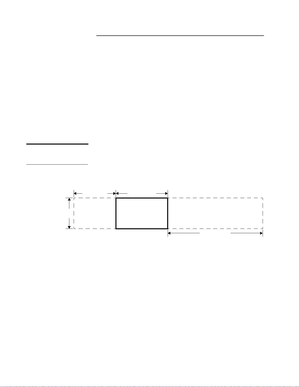
Bar code labels must conform to the specifications listed in table 2 and
the dimensions shown in figure 22.
Sample Number Min.
Wide/narrow ratio 2.60 2.60 2.60
a
Max. Average
Average bar error 0.02 0.11 0.06
Ref. decode passes A A A
Decode margin 74% 86% 80%
Symbol total 112.0 120.0 116.0
Print contrast signal 94% 98% 96%
Reflectance (light) 69% 75% 72%
Reflectance (dark) 1% 2% 1%
Symbol contr ast 65% 74% 70 %
Global threshold passes A A A
R(min.) R(max.) 2% 3% 2%
Modulation 52% 62% 58%
Edge contrast (min.) 37% 44% 41%
Defects 5% 28% 8%
30 ATL P1000 Series User’s Guide
Page 47

Chapter 2 Installing the P1000 Library
Preparing and Inserting Tape Cartridges
Figure 22 Bar Code Label
Dimensions
Sample Number Min.
a
Max. Average
Message length 6.00 6.00 6.00
Traditional tests PASS PASS PASS
Bar growth IN TOL IN TOL IN TOL
PCS OK OK OK
Print quality grade B C C
Formatting checks PASS PASS PASS
a. All bar code parameters should fall within the Min./Max. values when
tested using a PSC Quick Check 500 bar code tester.
Keepout region
(top & bottom)
Human-readable
alphanumeric text
Bar code
Open region
2.20
.06
.20
.30
.82
Figure 23 Inserting a Bar
Code Label
To label a cartridge, insert the label into the label area on the front edge
of the tape cartridge (see figure23).
ATL P1000 Series User’s Guide 31
Page 48

Chapter 2 Installing the P1000 Library
Preparing and Inserting Tape Cartridges
Setting the
Write-protect Switch
Figure 24 Setting the
Write-protec t Switch
The write-protect switch controls whether the tape cartridge is
2
write-protected or write-enabled:
•
Write-protecting a cartridge protects the data it contains from
being erased or overwritten. To write-protect a cartridge, move the
write-protect switch to the left (see figure 24). An orange tab
appears above the switch.
•
Write-enabling a cartridge allows new data to be written to the
cartridge or existing data to be modified or erased. To write-enable
a cartridge, move the write-protect switch to the right (see
figure 24). The orange tab disappears.
Placing Tape Cartridges in the Fixed Storage Bins
Orange tab
Write-protect switch
To place tape cartridges in the fixed storage bins:
2
Note:
Low-density P1000 libraries do not have fixed storage bins. If
you are using one of these libraries, skip this procedure and
proceed to the following section, “Placing Tape Cartridges in
the Load and Bulk Packs” on page 34.
Procedure
1
Open the library doors:
a
Locate the key in the accessories kit and unlock the front door
of the library.
b
Open the left door first, then open the right door.
32 ATL P1000 Series User’s Guide
Page 49

Chapter 2 Installing the P1000 Library
Preparing and Inserting Tape Cartridges
Procedure (continued)
2
Remove the load and bulk packs from the library (see figure 20 on
page 28):
a
Grip the load pack handles and squeeze them together.
This releases the latches securing the load pack.
b
Still holding the load pack handles, pull the load pack forward
and out of the library.
c
Repeat steps 2a and 2b to remove the bulk pack.
3
Set both packs aside.
4
Reaching in through the front doors of the library, insert a tape
cartridge into each of the nine storage bins above the tape drives.
(See figure 25 for the correct tape cartridge orientation.)
Each cartridge should slide into place with very little force. If a
cartridge does not slide into place easily, check the cartridge for
correct orientation and structural integrity.
Figure 25 Correct Tape
Cartridge Orientation
Insertion arrow
Bar code label
Write-protect switch
5
Insert a cartridge into each of the five storage bins above and
below the load port at the front of the library.
This requires you to reach into the library through the front doors
and then back toward the front. There are four bins above the load
port and one bin below.
6
Verify that each cartridge is properly seated in the bin (see
figure 25 for correct cartridge orientation).
ATL P1000 Series User’s Guide 33
Page 50

Chapter 2 Installing the P1000 Library
Preparing and Inserting Tape Cartridges
Placing Tape Cartridges in the Load and Bulk Packs
To place cartridges in the load and bulk packs:
2
Note:
This procedure assumes that you have already removed the
load and bulk packs. If not, remove the load and bulk packs,
referring to steps 2a through 2c on page 33.
Procedure
1
Load eight cartridges into each pack.
As you slide each cartridge into a bin, there should be initial
resistance from the r etention mechanism befor e the cartridge snaps
into place. If a cartridge does not snap into place, check for correct
orientation and structural integrity.
2
Verify that each cartridge is properly oriented and seated in the bin
(see figure 25 on page 33 for proper cartridge orientation).
Caution:
Handle the load and bulk packs with care. The
retention mechanism that secures the cartridges may be
compromised by rough handling, causing the cartridges
to fall out.
3
Reinstall the load and bulk packs:
a
Insert a pack into the library, cartridge-side first.
b
Line up the pack with the plastic guides on the top and bottom
of the library frame.
c
Slide the pack onto the guides until it snaps into place.
d
Repeat steps 3a through 3c for the other pack.
4
Close and lock the library doors.
34 ATL P1000 Series User’s Guide
Page 51

Chapter 2 Installing the P1000 Library
Connecting Host Computers
SCSI Cabling Guidelines
Note:
2
Connecting Host Computers
You are now ready to connect one or more host computers to the
library. You can connect up to five host computers on separate SCSI
busses.
If your library is equipped with the Prism FC210 Router, disregard this
section. Instead, see the
(PN 6331101).
When connecting the host computer(s) to the library, follow these
guidelines:
•
Connect each host to a SCSI connector on the back panel of the
library.
•
When more than one device is on a SCSI bus, daisy-chain the
devices using the SCSI cables from the accessories kit.
•
Terminate the last device on each SCSI bus.
Using these guidelines, you can set up variations of one-, two-, three-,
four-, or five-host configurations.
ATL PrismFC210 Router Addendum
2
SCSI Cabling Examples
Note:
2
The SCSI cable(s) to the host computer(s) must be supplied by the user.
This section provides three SCSI cabling examples. Each of these
examples follows the guidelines introduced above.
ATL P1000 Series User’s Guide 35
Page 52

Chapter 2 Installing the P1000 Library
Connecting Host Computers
Figure 26 Single-Host
SCSI Configuration
Host connector
15 in. (38 cm)
SCSI cable
In the single-host configuration (see figure 26), the host computer is
connected to the host connector on the rear panel of the library. Since
there is only one SCSI bus, use all of the SCSI cables from the
accessories kit to daisy-chain the library to each of the tape drives.
P1000 back panel
21 in. (53 cm)
SCSI cable
7 in. (18 cm)
SCSI cables
Terminator
To host computer
36 ATL P1000 Series User’s Guide
Page 53

Figure 27 Typical
Two-Host SCSI
Configuration
Host connector
Chapter 2 Installing the P1000 Library
Connecting Host Computers
In the two-host configuration (see figure 27), host 1 is connected to the
library and daisy-chained to tape drives 0 and 1 (upper drives). Host 2
is connected to tape drive 3 and daisy-chained to tape drive 2 (lower
drives). The first SCSI bus is terminated at drive 0; the second is
terminated at drive 2.
For this configuration, you need the following items from the
accessories kit:
•
both 7-inch SCSI cables
•
15-inch SCSI cable
•
2 SCSI terminators
P1000 back panel
15 in. (38 cm)
SCSI cable
Terminators
7 in. (18 cm)
SCSI cables
To host computers
ATL P1000 Series User’s Guide 37
Page 54

Chapter 2 Installing the P1000 Library
Connecting Host Computers
Figure 28 Five-Host SCSI
Configuration
Terminators
In the five-host configuration (see figure 28), five hosts are connected
to the library, requiring five SCSI terminators.
P1000 back panel
To host computers
38 ATL P1000 Series User’s Guide
Page 55

Chapter 2 Installing the P1000 Library
Turning On the Library
Turning On the Library
To turn on the library:
Procedure
1
Ver ify that:
•
all internal packaging is removed
•
the front doors and load port are closed
•
the library enclosure is installed
•
all back panel connections are secure
2
At the front panel, set the power switch on.
3
After several seconds, verify that the touch screen graphical user
interface (GUI) comes on.
2
ATL P1000 Series User’s Guide 39
Page 56

Chapter 2 Installing the P1000 Library
Configuring and Testing the Library
Table 3 Sample Library
Configuration
Configuring and Testing the Library
When you finish installing the library, make any desired changes to the
library configuration and then calibrate the library and test its
functionality.
Table 3 shows a sample library configuration.
Sample Default
Item
Model number 6220000
Number of bins (fixed storage and load pack) 30
Number of drives 4
Library SCSI ID number 0
Drive 0 SCSI ID number 2
Drive 1 SCSI ID number 3
Condition
2
Note:
Drive 2 SCSI ID number 4
Drive 3 SCSI ID number 5
Library power-up state On-line
Automatic drive cleaning function Disabled
Retry move command Enabled
Auto load from load port Disabled
Auto inventory at power up Enabled
No bar code scan Disabled
4/52 identity Disabled
To view and make changes to the configuration or to calibrate the
library, see chapter 4. To test the library, see chapter 5.
You must have either Operator or Service access privileges to access
the options described in chapter 4 and Service access privileges to
access the options described in chapter 5.
40 ATL P1000 Series User’s Guide
Page 57

Chapter 3
Chapter 3 Basic Operations
Basic Operations
This chapter describes the following basic library operating
procedures:
•
using the touch screen graphical user interface (GUI)
•
GUI components
•
GUI screens
•
obtaining library status
•
changing the GUI security level
•
performing manual operations
•
turning the library on and off
•
placing the library on- or off-line
•
inserting tape cartridges
•
opening the library doors
3
•
manually ejecting a tape cartridge
For more advanced procedures such as configuring, calibrating, or
testing the library, see chapters 4 and 5.
41ATL P1000 Series User’s Guide
Page 58

Chapter 3 Basic Operations
Using the GUI
Figure 29 GUI: Initial
Screen
Using the GUI
At start-up, the GUI displays the following screen (see figure 29).
Horizontal bar
Back Forward
ATL
PRODUCTS
System
Off-line
Standby
Vertical bar Main display
Load Port
Load Pack
U
Overview Tapes Operator
ATL
ATL
PRODUCTS
P1000
Home
area
3
GUI Components
Stop
From this screen, you can access controls to configure and operate the
library. All operating procedures in this chapter and in chapters 4
and 5 require an understanding of the GUI screens.
3
The GUI screen consists of the following components:
•
a vertical bar (at the left side of the screen)
•
a horizontal bar (at the top of the screen)
•
a main display area
These components are described in the following sections.
42 ATL P1000 Series User’s Guide
Page 59

Chapter 3 Basic Operations
Using the GUI
Table 4 Vertical Bar
Buttons and Indicators
Vertical Bar
Table 4 describes each of the buttons and indicators on the vertical bar.
Button/Indicator Description
Company logo This area of the screen displays the ATL logo.
Pressing the logo causes the GUI to display an
“About ATL” screen.
System status
indicator
Standby button Pressing the Standby button togg les the library
Load Port button Pressing the Load Port button causes the load port
Load Pack button Pressing the Load Pack button prepares the library
The system status indicator shows the current
state of the library and displays important
messages relating to library operation.
between on-line and standby status.
to open, allowing you to insert or remove a tape
cartridge.
for load pack removal. Always press this button
before opening the front door to access the load
pack.
3
Security level
indicator
The security level indicator displays the current
security level of the GUI. There are five security
levels: service (S), operator (O), user (U), import
only (I), and locked (L).
For more information about security levels, see
“Changing the GUI Security Level” on page 49.
Stop button Pressing the Stop button cuts power to the library
robotics, thus stopping all library activity.
Pressing the Stop button a second time restores
power to the library robotics.
ATL P1000 Series User’s Guide 43
Page 60

Chapter 3 Basic Operations
Using the GUI
Table 5 Horizontal Bar
Buttons
Horizontal Bar
Table 5 describes each of the buttons on the horizontal bar.
Button Description
Back button Pressing this button moves you backward
screen-by-screen through previously selected
screens.
Forward button Pressing this button moves you forward
screen-by-screen through previously selected
screens.
Home button Pressing this button returns you to the initial GUI
screen (see figure 29 on page 42).
Contrast buttons
(↑ and ↓)
Pressing these buttons adjusts the contrast of the
GUI.
Main Display Area
The main display area provides access to five tabbed screens through
which you can issue commands to the library. To view a screen, press
its corresponding tab.
3
3
Figure 30 Navigating
through the GUI Screens
Since the GUI is not large enough to display all five tabbed screens at
once, the initial GUI screen displays only the first three screens
(Overview, Tapes, and Operator). To scroll forward to the remaining
screens (Service and Prism Router), press the right arrow button.
To scroll backward through the screens, press the left arrow button.
Press this button
to scroll to
previous tabs.
ATL
PRODUCTS
System
Report
Off-line
Standby
Load Port
Load Pack
Statistics
Actuator
S
Stop
Back Forward
Operator
SysTest
Library
Results
Auto
Clean
Home
Tapes
Test Misc.
SysTest
Library
Operate
Axes
Service
Calibrate
Service
Initialize
Nonvol
Statistics
Initialize
Nonvol
Config
Change
Password
ATL
PRODUCTS
System
Off-line
Standby
Load Port
Load Pack
U
Stop
Press this button
to scroll to the
next tabs.
Back Forward
Overview Tapes Operator
Drives Activity Load Pack
D00
ANF 120
Ready
D01
???
Ready
D02
empty
Ready
D03
ANF 123
Ready
GRP
empty
Home
P00
ANF146
P01
ANF147
P02
ANF148
P03
ANF149
44 ATL P1000 Series User’s Guide
Page 61

Table 6 describes each of the GUI screens.
Chapter 3 Basic Operations
Using the GUI
Table 6 GUI Screens
GUI Screens
Screen Description
Overview This screen provides an overview of the tape
drives, robot activity, and load pack inventory.
Tapes This screen displays the contents of the tape
drives, storage bins, load packs, the gripper, and
the load port.
Operator This screen contains the library configuration and
control functions. To use this screen, you must
have Operator or Service access privileges.
Service This screen contains reporting functions, system
tests, and miscellaneous commands. To use this
screen, you must have Service access privileges.
Prism Router This screen contains options related to the
optional Prism FC210 Router. For information
about these options, see the
Router Addendum
3
Figure 31 shows the commands that are available on the Overview,
(PN 6331101).
ATL Prism FC210
Tapes, Operator, and Service screens.
Figure 31 GUI Screens
Overview Tapes Operator
Tape Drive Status
Activity
Load Pack
Drives
Storage
Load Pack
Transport
Load Port
Configure Library
Configure Options
Move Cartridges
Inventory Tapes
Calibrate Library
Exercise Library
Unload Drive
Unload Imp/Exp
Service
Statistics
Actuator
Sys Test Library Results
Auto Clean
Sys Test Library
Operate Axes
Service Calibrate
Initialize Nonvol Statistics
Initialize Nonvol Config.
Change Password
ATL P1000 Series User’s Guide 45
Page 62

Chapter 3 Basic Operations
Obtaining Library Status
Overview Screen
Figure 32 Overview
Screen
ATL
PRODUCTS
Obtaining Library Status
You can obtain library status from the Overview and Tapes screens.
3
Back Forward
Overview Tapes Operator
To open the Overview screen, press the Overview tab on the GUI.
The Overview screen is divided into three sections (see figure 32):
•
Drives
•
Activity
•
Load Pack
Home
3
System
Off-line
Standby
Load Port
Load Pack
U
Stop
Drives Activity Load Pack
D00
ANF 120
Ready
D01
???
Ready
D02
empty
Ready
D03
ANF 123
Ready
GRP
empty
P00
ANF146
P01
ANF147
P02
ANF148
P03
ANF149
Drive
status
Drive
number
Compression
enabled
D03
ANF 123
Ready
Cartridge
present
Bar
code
Writeenabled
46 ATL P1000 Series User’s Guide
Page 63

Chapter 3 Basic Operations
Obtaining Library Status
Figure 33 Overview
Screen with Expanded
Tape Drive Status
Drives
The Drives section of the Overview screen displays the following
information:
•
whether a tape drive has a cartridge
•
the bar code number of the cartridge (if a cartridge is present and
the labe l is readable)
•
whether the cartridge is write-enabled or write-protected
•
whether compression is enabled
To view more detailed information about drive status, press the
Overview screen anywhere in the Drives section. This opens a Tape
Drive Status box (see figure 33). Use the arrow buttons to scroll
through the list of drives. To return to the Overview screen, press the
Tape Drive Status box.
ATL
PRODUCTS
Back Forward
Overview
Tapes Operator
Home
3
System
Off-line
Standby
Load Port
Load Pack
U
Stop
Tape Drive Status Activity Load Pack
D03
ANF 123
Compression ON
Write Protect OFF
DLT7000
CompacTape IV
SCSI ID: 05
Ready
GRP
empty
P00
ANF146
P01
ANF147
P02
ANF148
P03
ANF149
Activity
The Activity section of the Overview screen displays the source
element, transport medium, and destination element involved in any
current move activity.
3
ATL P1000 Series User’s Guide 47
Page 64

Chapter 3 Basic Operations
Obtaining Library Status
Tapes Screen
Figure 34 Tapes Screen
Load Pack
3
The Load Pack section of the Overview scr een identif ies the cartri dges
currently stored in the load pack. Press the arrow buttons at the
bottom of the screen to scroll through the load pack bins and view
their contents.
You can also view this information using the Tapes screen.
3
To open the Tapes screen, press the Tapes tab on the GUI. Use this
screen to determine whether a particular element contains a tape
cartridge, and whether the cartridge is labeled.
ATL
PRODUCTS
System
Off-line
Standby
Back Forward
Overview Tapes Operator
Drives
00
EMPTY
Storage Load Pack Transport
000
ANF 099
Home
P00
ANF 146
GRP
EMPTY
Load Port
Load Pack
U
Stop
01
EMPTY
02
EMPTY
03
EMPTY
001
ANF 100
002
ANF 101
003
ANF 102
P01
ANF 147
P02
ANF 148
P03
ANF 149
Load Port
LP
EMPTY
The Tapes screen is divided into sections by element type. To
determine whether a particular element contains a cartridge, look at
the appropriate section of the screen. For example, to determine
whether there is a cartri dge in the gripper, look at the Transport section
of the screen.
The Storage and Load Pack sections contain too many elements to
display on the screen at one time. Use the arrow buttons at the bottom
of these sections to scroll through the section.
You can also expand the Storage or Load Pack sections to fill the screen
by pressing the desired section anywhere above the arrow buttons. To
return to the start of the Tapes screen, press the Back button.
48 ATL P1000 Series User’s Guide
Page 65

Chapter 3 Basic Operations
U
I
L
Changing the GUI Security Level
Table 7 GUI Security
Levels
Changing the GUI Security Level
Table 7 describes the five levels of security for the P1000 library GUI.
The security level indicator at the lower left corner of the GUI indicates
the current security level.
Security Level Indicator Description
Service (S) This security level provides access to all
Operator (O) This security level provides access to the
User (U) This security level provides access to the
Import Only (I) This security level provides access to the
S
GUI screens (Overview, Tapes, Operator,
and Service) and all functions on the
vertical bar.
O
Overview , Tapes, and Operator screens, and
all functions on the vertical bar.
Overview and Tapes screens, and all
functions on the vertical bar.
Overview and Tapes screens, and the Load
Port button on the vertical bar . This security
level prevents access to the Stop or Standby
buttons on the vertical bar.
3
Securing the GUI
3
Note:
Locked (L) This security level provides access to the
Overview and Tapes screens only. This
security level prevents access to any
functions on the vertical bar.
The default security level is User. This security level provides access to
the Overview and Tapes screens and the functions on the vertical bar.
It does not provide access to the Operator and Service screens.
This procedure is especially useful for changing from the Operator or
Service security levels to the User level after executing an Operator or
Service level command.
ATL P1000 Series User’s Guide 49
Page 66

Chapter 3 Basic Operations
Changing the GUI Security Level
To change the security level:
Procedure
1
Press the security level indicator at the lower left corner of the GUI.
The GUI displays the Password screen (see figure 35).
Figure 35 Password
Screen
ATL
PRODUCTS
System
Off-line
Standby
Load Port
Load Pack
Back Forward
Operator
Password
Enter
Password:
Security
Level:
Service
User
Tapes
_
Import Only
Home
Operator
Service
1 2
3 4
5 6
7 8
9 0
S
Locked
Stop
2
Press the button that corresponds to the desired security level
(Service, Operator, User, Import Only, or Locked).
3
If prompted, enter a password.
Select
A password is r equir ed to enter a se curity level higher t han the one
currently set.
The default passwords are:
•
Service: 5678
•
Operator: 1234
•
User: 2222
•
Import Only: 1111
4
Press the Select button.
The GUI displays a screen indicating that the new security level
has been set successfully.
5
Press Okay.
The security level indicator displays the new security level (S, O,
U, I, or L).
50 ATL P1000 Series User’s Guide
Page 67

Chapter 3 Basic Operations
Performing Manual Operations
T u rning On the Library
Performing Manual Operations
3
This section describes procedures requiring operator intervention.
These procedures consist of:
•
turning the library on
•
placing the library on-line
•
placing the library off-line
•
turning the library off
•
inserting tape cartridges
•
opening the library doors
•
manually ejecting a tape cartridge
3
To turn on the library:
Procedure
1
Ver ify that:
Placing the Library
On-line
3
Note:
•
all internal packaging is removed
•
the front doors and load port are closed
•
the library enclosure is installed
•
all back panel connections are secure
2
At the front panel, set the AC power switch on.
3
After several seconds, verify that the GUI comes on.
To place the library on-line:
You must have Operator level access privileges or higher to perform
this procedure (see “Changing the GUI Security Level” on page 49).
Procedure
1
With the library turned on and the GUI indicating “System Offline,” press the Standby button on the GUI.
2
Verify that the GUI displays “System On-line.”
ATL P1000 Series User’s Guide 51
Page 68

Chapter 3 Basic Operations
Performing Manual Operations
Placing the Library
Off-line
T urning Off the Library
3
Note:
3
To place the library off-line:
You must have Operator level access privileges or higher to perform
this procedure (see “Changing the GUI Security Level” on page 49).
Procedure
1
With the library turned on and the GUI indicating “System
On-line,” press the Standby button on the GUI.
2
Verify that the GUI displays “System Off-line.”
To turn off the library:
Procedure
1
Place the library off-line (see the previous section, “Placing the
Library Off-line”).
The library completes the current command and then stops.
2
Verify that the GUI displays “System Off-line.”
3
Verify that the gripper is empty by checking the Overview screen.
Inserting Tape Cartridges
3
Note:
4
If there is a t ape cartridge in the gripper, execute a Move command
to place the cartridge in an empty bin or drive (see “Moving a
Cartridge” on page 64).
5
At the front panel, set the power switch off.
Caution:
Always leave the library power off for at least 15 seconds
before turning it on again.
This section explains how to insert tape cartridges.
You must have Import Only level access privileges or higher to
perform this procedure (see “Changing the GUI Security Level” on
page 49).
Caution:
Do not use CompacTape I™, CompacTape II™, or
CompacTape IIIXT™ tape cartridges in this library.
52 ATL P1000 Series User’s Guide
Page 69

Chapter 3 Basic Operations
Performing Manual Operations
Caution:
Examine all cartridges before loading them into the library
or tape drive. Look for label stock or other foreign material
that may be clinging to the cartridges.
Procedure
1
Prepare the tape cartridge to be inserted by labeling it and setting
the write-protect switch as desired (see “Preparing and Inserting
Tape Cartridges” on page 30).
2
Press the Load Port button on the left side of the GUI.
The library unlocks the load port, and the load port door springs
open slightly.
Warning:
Mechanical hazards may be exposed when the load port is
partially open or closed. Do not attempt to insert your
hands or fingers into the load port opening at any time.
3
Open the load port door completely.
4
Place the tape cartridge into the load port slot, label-side first (see
figure 25 on page 33 for proper cartridge orientation).
5
Manually close the load port door.
If auto load is enabled, the library automatically moves the
cartridge to an available bin.
6
Repeat steps 1 through 5 to insert other tape cartridges.
Note:
To remove tape cartridges using the load port, see “Moving a
Cartridge” on page 64.
ATL P1000 Series User’s Guide 53
Page 70

Chapter 3 Basic Operations
Performing Manual Operations
Figure 36 Inserting a Tape
Cartridge
Bar code label
Tape cartridge
Load port
Opening the Library Doors
Open the front doors to access a tape drive, access the load and bulk
3
packs, or to load the library with tape cartridges.
To open the library doors:
Procedure
1
If the door is locked, unlock it.
2
Press the Load Pack button on the left side of the GUI.
The library completes any current command and then unlocks the
load pack door.
3
Open the left door first, and then open the right door.
4
To close the doors, reverse this procedure.
54 ATL P1000 Series User’s Guide
Page 71

Chapter 3 Basic Operations
Performing Manual Operations
Manually Ejecting a Cartridge
3
Note:
To manually eject a tape cartridge from one of the tape drives:
You must have Import Only level access privileges or higher to
perform this procedure (see “Changing the GUI Security Level” on
page 49).
Procedure
1
Open the library front doors (see “Opening the Library Doors” on
page 54).
2
Remove the load and bulk packs from the library (see “Removing
the Load and Bulk Packs” on page 27) and set them aside.
3
Press the Unload button on the desired drive (see drive product
manual) and wait for the Operate Handle indicator to light.
Note:
When you press Unload, the tape cartridge rewinds.
Depending on the tape cartridge position, this may take from
10 to 120 seconds. When the rewind process is complete, the
Operate Handle indicator lights.
4
When the Operate Handle indicator lights, raise the insert/release
handle to eject the tape cartridge.
5
Wait for two seconds, then grasp the tape cartridge and slowly pull
it halfway out of the tape drive.
Caution:
If the tape cartridge leader fails to detach from the take-up
leader, push the tape cartridge all the way back into the
drive, press down the insert/release handle, and return to
step 4. Otherwise, proceed to step 6.
6
Pull the tape cartridge completely out of the drive.
7
Reinstall the load and bulk packs (see page 34).
Be sure to line up the guides on the top and bottom of the load and
bulk packs with the tabs on the mounting frame.
8
Close and lock the library doors.
ATL P1000 Series User’s Guide 55
Page 72

Chapter 3 Basic Operations
Performing Manual Operations
56 ATL P1000 Series User’s Guide
Page 73

Chapter 4
Chapter 4 Operator Commands
Operator Commands
This chapter describes the commands on the Operator screen of the
touch screen graphical user interface (GUI). Using this sc reen, you can:
•
configure the library
•
configure library options
•
move a tape cartridge
•
inventory the tape cartridges
•
calibrate the library
•
exercise the library
•
unload a tape drive
•
unload the load port
The Operator screen is restricted to persons with Operator or Service
access privileges.
4
Note:
Note:
The commands on the Operator screen are operational only when the
library is in Standby mode.
This chapter assumes you are familiar with the P1000 GUI. If you are
not, see “Using the GUI” on page 42 for more information.
57ATL P1000 Series User’s Guide
Page 74

Chapter 4 Operator Commands
Accessing the Operator Screen
Figure 37 Enter Password
Screen
Accessing the Operator Screen
To access the Operator screen:
Procedure
1
On the GUI, press the Operator tab.
The GUI displays the Enter Password screen (see figure 37).
ATL
PRODUCTS
System
Off-line
Standby
Load Port
Back Forward
Overview Tapes Operator
Enter Password
Enter Password: _
Home
1 2
3 4
5 6
4
Load Pack
U
Stop
2
Enter the Operator or Service password.
Note:
The default Operator password is 1234. To change the Operator
password, see “Changing Passwords” on page 83. Changing
passwords requires Service level access privileges.
7 8
9 0
Enter
58 ATL P1000 Series User’s Guide
Page 75

Chapter 4 Operator Commands
Accessing the Operator Screen
Procedure (continued)
3
If the password you entered i s valid, the GUI displays the Operator
screen (see figure 38).
Figure 38 Operator
Screen
ATL
PRODUCTS
System
Off-line
Standby
Load Port
Load Pack
O
Stop
Back Forward
Overview Tapes Operator
Config.
Configure
Library
Configure
Options
Control
Move
Cartridges
Inventory
Tapes
Home
Calibrate
Library
Exercise
Library
Unload
Drive
Unload
Imp/Exp
ATL P1000 Series User’s Guide 59
Page 76

Chapter 4 Operator Commands
Configuring the Library
Figure 39 Configure:
Library Screen
Configuring the Library
The Configure Library command allows you to view or change the
following library configuration information:
•
library model number
•
number of storage bins
•
number of drives
•
library SCSI ID
•
tape drive SCSI IDs
To view or change the library configuration:
Procedure
1
On the Operator screen, press the Configure Library button.
The GUI displays the Configure: Library screen (see figure 39).
ATL
PRODUCTS
Back Forward
Overview Tapes Operator
Home
4
System
Off-line
Standby
Load Port
Load Pack
O
Stop
2
Press the Configure button.
Configure: Library
Inquiry: P1000 6220000
Model: 6220000
# Bins: 30
# Drives: 4
Library SCSI ID: 0
Drive 0 SCSI ID: 2
Drive 1 SCSI ID: 3
Drive 2 SCSI ID: 4
Drive 3 SCSI ID: 5
Configure
The GUI displays the Configure: Library Settings screen (see
figure 40).
60 ATL P1000 Series User’s Guide
Page 77

Chapter 4 Operator Commands
Configuring the Library
Figure 40 Configure:
Library Settings Screen
ATL
PRODUCTS
System
Off-line
Standby
Load Port
Load Pack
Back Forward
Overview Tapes Operator
Configure: Library Settings
Model:
# Bins: 30
# Drives:
Load Port:
6220000
4
Enabled
Home
Select
O
Device: Library
Stop
SCSI ID: 0
Change
Procedure (continued)
3
To change any of the configuration information displayed on this
screen:
a
Press the Select button repeatedly until the desired option is
highlighted.
Note:
To change the SCSI ID of the library or a tape drive, first select
the desired device, and then select the desired SCSI ID.
Remember that SCSI devices on each bus must have a unique
number from 0 to 15. SCSI devices include the library robotics,
the host computer, the library tape drives, and internal and
external hard disk drives.
b
Press the arrow buttons to scroll through the available settings
for that option.
c
When the desired setting is displayed, press the Change
button.
The setting is now saved as part of the library configuration.
d
Repeat steps 3a through 3c to make additional changes to the
library configuration.
4
Press the Back button to return to the Operator screen.
ATL P1000 Series User’s Guide 61
Page 78

Chapter 4 Operator Commands
Configuring Library Options
Table 8 Available
Settings, Configure:
Options Screen
Configuring Library Optio ns
The Configure Options command allows you to set the following
options (see table 8).
Option Settings Description
Power-On Online
Offline
Auto Clean Enable
Disable
Retries Enable
Disable
Auto Inventory Enable
Disable
This setting determines whether the
library will be on-line or off-line
when it is powered up.
When this option is enabled, the
library performs drive cleaning tasks
automatically when required.
When this option is enabled, the
library retries a failed command
automatically before issuing an error
message.
When this option is enabled, the
library performs an inventory
automatically upon power-up.
4
Barcode Labels Enable
Disable
Temp. Detection Enable
Disable
Auto Load Disable
Enable
Power-On Security User
Locked
Import Only
Operator
4/52 Identity Enable
Disable
When this option is enabled, the
library scans bar codes during
inventory. Disable this option when
using unlabeled cartridges.
When this option is enabled, the
over-temperature detection warning
and shut down features of the library
are activated.
When this option is enabled, the
library automatically moves any
cartridge placed in the load port into
an empty cartridge bin.
This option sets the security level
that will be used when the library is
initially powered up.
For a description of these security
levels, see “Changing the GUI
Security Level” on page 49.
When this option is enabled, the
library returns the same inquiry
string as the ATL 4/52 library.
62 ATL P1000 Series User’s Guide
Page 79

Chapter 4 Operator Commands
Configuring Library Options
To set one of the options on the Configure: Options screen:
Procedure
1
On the Operator screen, press the Configure Options button.
The GUI displays the Configure: Options screen (see figure 39).
Figure 41 Configure:
Options Screen
Back Forward
ATL
PRODUCTS
System
Off-line
Standby
Load Port
Load Pack
Configure: Options
O
Stop
2
Press the button that corresponds to the option you wish to
Overview Tapes Operator
Power-On
Retries
Barcode
Labels
Auto
Load
4/52
Identity
Auto
Clean
Auto
Inventory
Temp.
Detection
Power-On
Security
Home
Current
Value:
New V alue:
Online
Execute
change.
3
Using the arrow buttons, scroll through the available option
settings.
4
When the desired setting appears in the New Value field, press the
Execute button.
The new value is added to the library configuration.
5
Repeat steps 2 through 4 to make any other configuration changes.
6
Press the Back button to return to the Operator screen.
ATL P1000 Series User’s Guide 63
Page 80

Chapter 4 Operator Commands
Moving a Cartridge
Figure 42 Control: Move
Cartridge Screen
Note:
Moving a Cartridge
The Move Cartridges command enables you to move tape cartridges
from one library element to another. Library elements consist of
storage bins, tape drives, the load port, or the gripper.
Before moving a cartridge from a tape drive, prepare the cartridge by
issuing an Unload Drive command (see “Unloading a Drive” on
page 70).
To move a cartridge:
Procedure
1
On the Operator screen, press the Move Cartridges button.
The GUI displays the Control: Move Cartridge screen (see
figure 42).
Backspace button
Back Forward
Home
4
ATL
PRODUCTS
System
Off-line
Standby
Load Port
Load Pack
O
Stop
Overview Tapes Operator
Control: Move Cartridge
Source:
Destination:
Range:
_
Execute
Storage Bin
Drive
Load Port
Gripper
1 2
3 4
5 6
7 8
9 0
Select
64 ATL P1000 Series User’s Guide
Page 81

Chapter 4 Operator Commands
Moving a Cartridge
Procedure (continued)
2
Identify the source element (the element containing the cartridge
to be moved):
a
Press the appropriate element button (Storage Bin, Tape Drive,
Load Port, or Gripper).
The GUI displays a range of addresses in the Range box (below
the Destination box).
b
Using the keypad, enter the address of the source element.
If you make a mistake inputting the address, press the
backspace button to erase the entry character by character.
c
Press the Select button.
The Source box displays the source information and the
Destination box becomes active.
3
Identify the destination element:
a
Press the appropriate element button (Storage Bin, Tape Drive,
Load Port, or Gripper).
The GUI displays a range of addresses in the Range box (below
the Destination box).
b
Using the keypad, enter the address of the source element.
If you make a mistake inputting the address, press the
backspace button to erase the entry character by character.
The destination information appears in the Destination box as
you type.
4
Press the Execute button to initiate the move.
The GUI displays a “Command In Progress” screen. When the
move is complete, the “Command In Progress” screen disappears.
To cancel the move, press the Abort button on the screen.
5
Press the Back button to return to the Operator screen.
ATL P1000 Series User’s Guide 65
Page 82

Chapter 4 Operator Commands
Performing an Inventory
Performing an Inventory
The Inventory Tapes command records the bar code labels of the
cartridges in the tape drives, fixed storage bins, load pack bins, and the
load port. Library elements containing unlabeled cartridges are
marked full with no label.
To perform an inventory, press the Inventory Tapes button on the
Operator screen. The GUI displays a “Command In Progress” screen.
The inventory process continues until all storage elements have been
checked. To cancel the inventory process, press the Abort button on the
screen.
4
66 ATL P1000 Series User’s Guide
Page 83

Chapter 4 Operator Commands
Calibrating the Library
Figure 43 Calibrate Libra ry
Screen
Note:
Calibrating the Library
The Calibrate Library command sets the horizontal and vertical
graduations used by the library to position the gripper for pick and
place operations. Once calibrated, the library can determine the exact
position of any library element.
Calibrate the library during the initial installation and after any
maintenance procedure.
To calibrate the library:
Procedure
1
On the Operator screen, press the Calibrate Library button.
The GUI displays the Calibrate Library screen (see figure 43).
ATL
PRODUCTS
Back Forward
Overview Tapes Operator
Home
4
System
Off-line
Standby
Load Port
Load Pack
Calibrate Library
Calibrate
All
Calibrate
Drives
Calibrate
Imp/Exp
Calibrate
Bins
O
Stop
2
Press the button that corresponds to the desired calibration
operation:
•
Calibrate All calibrates the drives, bins, and load port.
•
Calibrate Drives calibrates the drives only.
•
Calibrate Imp/Exp calibrates the load port only.
•
Calibrate Bins calibrates the storage bins only.
ATL P1000 Series User’s Guide 67
Page 84

Chapter 4 Operator Commands
Calibrating the Library
The GUI displays a “Command In Progress” screen during the
calibration process.
To cancel the calibration process, press the Abort button.
3
When the calibration is complete, press t he Back button to ret urn to
the Operator screen.
68 ATL P1000 Series User’s Guide
Page 85

Chapter 4 Operator Commands
Exercising the Library
Exercising the Library
The Exercise Library command tests the rob otics and the calibration by
moving cartridges randomly from one storage location to another.
To exercise the library, press the Exercise Library button on the
Operator screen. The GUI displays a “Command In Progress” screen.
The exercise process runs continuously until you press the Abort
button or an error is detected.
4
ATL P1000 Series User’s Guide 69
Page 86

Chapter 4 Operator Commands
Unloading a Drive
Figure 44 Control: Unload
Drive Screen
Unloading a Drive
The Unload Drive command prepares a tape cartridge to be ejected
from a drive by disengaging the tape from the read/write heads and
rewinding it. After unloading the drive, eject and remove the cartridge
using the Move Cartridges command (see “Moving a Cartridge” on
page 64).
To unload a drive:
Procedure
1
On the Operator screen, press the Drive Unload button.
The GUI displays the Control: Unload Drive screen (see figure 44).
ATL
PRODUCTS
System
Off-line
Back Forward
Overview Tapes Operator
Control: Unload Drive
Home
4
Standby
Load Port
Load Pack
O
Stop
2
Use the arrow buttons to highlight the desired drive.
3
Press the Execute button.
Drive 0
Execute
The GUI displays a “Command In Prog r ess” s cr een and the library
unloads the drive.
To cancel the Unload Drive command, press the Abort button.
4
Press the Back button to return to the Operator screen.
70 ATL P1000 Series User’s Guide
Page 87

Chapter 4 Operator Commands
Unloading the Load Port
Note:
Unloading the Load Port
The Unload Imp/Exp command moves a tape cartridge from the load
port to an available storage bin. Use this command to move a tape
cartridge from the load port when the Auto Load option is disabled
(see “Configuring Library Options” on page 62).
You can also use the Move Cartridges command to unload the load
port (see “Moving a Cartridge” on page 64). This command is
especially useful if the destination of the move is important.
To unload the load port using the Unload Imp/Exp command, press
the Unload Imp/Exp button on the Operator screen. The GUI displays
a “Command In Progress” screen. To cancel the Unload Imp/Exp
command, press the Abort button.
4
ATL P1000 Series User’s Guide 71
Page 88

Chapter 4 Operator Commands
Unloading the Load Port
72 ATL P1000 Series User’s Guide
Page 89

Chapter 5
Chapter 5 Service Commands
Note:
Service Commands
This chapter describes the commands on the Service screen of the
touch screen graphical user interface (GUI). Using this sc reen, you can:
•
generate reports
•
test the library
•
initialize nonvolatile information
•
change passwords
The Service screen is restricted to persons with Service access
privileges.
This chapter assumes you are familiar with the P1000 GUI. If you are
not, see “Using the GUI” on page 42 for more information.
5
73ATL P1000 Series User’s Guide
Page 90

Chapter 5 Serv ice Commands
Accessing the Service Screen
Figure 45 Enter Password
Screen
Accessing the Service Screen
To access the Service screen:
Procedure
1
On the GUI, press the right arrow button.
The GUI displays the Service tab.
2
Press the Service tab.
The GUI displays the Enter Password screen (see figure 45).
ATL
PRODUCTS
System
Off-line
Standby
Back Forward
Operator
Enter Password
Tapes
Home
Service
5
1 2
3 4
Load Port
Load Pack
Enter Password: _
O
Stop
3
Enter the Service password.
Note:
The default Service password is 5678. To change the Service
password, see “Changing Passwords” on page 83. Changing
passwords requires Service level access privileges.
5 6
7 8
9 0
Enter
74 ATL P1000 Series User’s Guide
Page 91

Chapter 5 Service Commands
Accessing the Service Screen
Procedure (continued)
4
If the password you entered is valid, the GUI displays the Service
screen (see figure 46).
Figure 46 Service Screen
ATL
PRODUCTS
System
Off-line
Standby
Load Port
Load Pack
S
Stop
Back Forward
Operator
Report
Statistics
Actuator
SysTest
Library
Results
Auto
Clean
Home
Tapes
Test Misc.
SysTest
Library
Operate
Axes
Service
Calibrate
Service
Initialize
Nonvol
Statistics
Initialize
Nonvol
Config
Change
Password
ATL P1000 Series User’s Guide 75
Page 92

Chapter 5 Serv ice Commands
Generating Reports
Generating Reports
The Report section of the Service screen enables you to generate
on-screen reports about:
•
statistics regarding library operation
•
actuator positions and status
•
system test results
•
AutoClean status and tracking information
To generate a report, press the appropriate button in the Report sec tion
of the Service screen. Within a few seconds, the GUI displays the
report on the screen.
Use the arrow buttons at the right side of the screen to scroll through
the report page by page. When you are finished viewing the report,
press the Back button to return to the Service screen.
Figure 47 shows a sample statistics report scr een (obtained by pr essing
the Statistics button on the Service screen).
5
Figure 47 Report:
Statistics Screen
ATL
PRODUCTS
System
Off-line
Standby
Load Port
Load Pack
S
Stop
Back Forward
Operator
Report: Statistics
Power On Time (Hr: Min: Sec): 360: 05: 56
Command Time (Hr: Min: Sec): 108: 08: 17
Pick Bin Count: 26501
Place Bin Count: 26435
Pick Drive Count: 11323
Place Drive Count: 10143
Pick Load Port Count: 873
Place Load Port Count: 877
Horizontal Move Count: 268831
Vertical Move Count: 152238
Tapes
Home
Service
Update
76 ATL P1000 Series User’s Guide
Page 93

Chapter 5 Service Commands
Generating Reports
Figure 48 shows a sample actuator status report screen (obtained by
pressing the Actuator button on the Service screen).
Figure 48 Report: Actuator
Status Screen
ATL
PRODUCTS
System
Off-line
Standby
Load Port
Load Pack
Back Forward
Operator
Report: Actuator Status
Horizontal Position (in.): 8.752
Vertical Position (in.): 3.126
Extension Position (in.): 0.015
Gripper Position: Closed
Rotary Position: Front
Tapes
Home
Service
S
Stop
Figure 49 shows a sample SysTest Library results report screen
(obtained by pressing the SysTest Library Results button on the Service
screen).
Figure 49 Report: SysTest
Library Results Screen
ATL
PRODUCTS
System
Off-line
Standby
Load Port
Load Pack
S
Stop
Back Forward
Operator
Report: SysTest Library Results
Pick and Place Total Count: 62466
System Test Status: B 80 0B
T otal Test Time (Hr:Min:Sec): 61:42:35
T est Type: Random
Avg. Drive to Bin Move Time (Sec): 0.000
Avg. Bin to Drive Move Time (Sec): 0.000
Avg. Bin to Bin Move Time (Sec): 0.000
Longest Move Time (Sec): 0.000
Bad Barcode Reading Count: 0
Place to Drive Count: 2221
Place to Bin Count: 14202
Place to Load Port Count: 2
Tapes
Home
Service
ATL P1000 Series User’s Guide 77
Page 94

Chapter 5 Serv ice Commands
Generating Reports
Figure 50 shows a sample AutoClean status r eport scr een (obta ined by
pressing the Auto Clean button on the Service screen).
Figure 50 Report:
AutoClean Status Screen
ATL
PRODUCTS
System
Off-line
Standby
Load Port
Load Pack
S
Stop
Back Forward
Operator
Report: AutoClean Status
Auto Clean Enabled: FALSE
Auto-Clean State: Idle
Cleaning Operation Count: 0
Bad Operation Count: 0
Untracked Operation Count: 0
Last to Drive Error Status: 0 00 00
Last to Load Port Error Status: 0 00 00
Last to Home Error Status: 0 00 00
Tapes
Home
Service
78 ATL P1000 Series User’s Guide
Page 95

Chapter 5 Service Commands
Testing the Library
Performing a System T est
Figure 51 Test: SysTest
Library Screen
Note:
5
Testing the Library
The Test section of the Service screen provides three options:
•
SysTest Library
•
Operate Axes (not currently supported)
•
Service Calibrate
The commands in the Test section of the Service screen are operational
only when the library is in Standby mode.
To perform a system test:
Procedure
1
On the Service screen, press the SysTest Library button.
The GUI displays the Test: SysTest Library screen (see figure 51).
ATL
PRODUCTS
Back Forward
Operator
Tapes
Home
Service
5
System
Off-line
Standby
Load Port
Load Pack
S
Stop
2
Select one of the following system test options:
•
To test storage bins only, press the Swap Bins button.
•
To test drives only, press the Swap Drives button.
•
To test both bins and drives, press both the Swap Bins and
Test: Systest Library
Random
Swap
Bins
Swap
Drives
Use
Barcodes
# of Runs:
_
Continuous
Execute
Swap Drives buttons.
1 2
3 4
5 6
7 8
9 0
Select
ATL P1000 Series User’s Guide 79
Page 96

Chapter 5 Serv ice Commands
Testing the Library
Procedure (continued)
3
Select all desired test options:
•
To swap cartridges randomly, press the Random button.
If you do not press this button, cartridges are swapped
sequentially from the first bin or drive.
•
To have the library read the bar code as it swaps each cartridge,
press the Use Barcodes button.
•
To have the test run continuously until aborted, press the
Continuous button. Otherwise, enter the number of times you
want the test to run into the # of Runs box.
4
When you have selected the test and all test options, press the
Execute button.
The GUI displays a “Command In Progress” screen.
To cancel the system test, press the Abort button.
Performing a Service Calibration
5
Note:
Note:
If you selected the Continuous option in step 3, you must press
the Abort button to stop the test.
The Service Calibrate command autocalibrates the library (the tape
drives, the cartridge bins, and the load port) and saves the target
locations as a baseline for all subsequent calibration procedures.
Before performing a service calibration, remove all tape cartridges
from the library.
To perform a service calibration, press the Calibrate Library button on
the Service screen. The GUI displ ays a “Command In Progress” screen
during the calibration process.
To cancel the calibration process, press the Abort button.
80 ATL P1000 Series User’s Guide
Page 97

Chapter 5 Service Commands
Initiali zing Nonvolatile Information
Initializing Nonvolatile Information
The library nonvolatile memory resides on the robotic controller card.
It retains library configuration information, calibration information,
and statistics. This information should be initialized only by an
authorized field service engineer when r eplacing t he r obotic contr oll er
card.
The Service screen provides two commands involving information
stored in nonvolatile memory:
•
Initialize Nonvol Statistics—This command purges nonvolatile
memory of all statistical information about library operation. This
information is used to generate the library statistics report (see
“Generating Reports” on page 76).
•
Initialize Nonvol Config—This command returns library
configuration settings to the factory default condition, eliminating
current calibration data and any changes made using the
Configure Library and Configure Options commands.
5
ATL P1000 Series User’s Guide 81
Page 98

Chapter 5 Serv ice Commands
Initializing Nonvolatile Information
To execute a nonvolatile memory command:
Procedure
1
On the Service screen, press the appropriate command button
(Initialize Nonvol Statistics or Initialize Nonvol Config).
The GUI displays a confirmation screen (see figure 52).
Figure 52 Confirmation
Screen
Back Forward
ATL
PRODUCTS
System
Off-line
Standby
Load Port
Load Pack
S
Stop
2
Press Continue to execute the command.
Report
Cancel or Continue
This will reset the library configuration. Continue?
Continue Cancel
Test Misc.
To cancel the command, press the Cancel button.
Home
ServiceOperatorTapes
Initialize
Nonvol
Statistics
Initialize
Nonvol
Config
Change
Password
82 ATL P1000 Series User’s Guide
Page 99

Chapter 5 Service Commands
Changing Passwords
Figure 53 Service:
Change Password Screen
Changing Passwords
The Change Password command enables you to change the pas swords
for four of the GUI security levels: Import Only, User, Operator, and
Service. For information about the GUI security levels, see “Changing
the GUI Security Level” on page 49.
To change a password:
Procedure
1
On the Service screen, press the Change Password button.
The GUI displays the Service: Change Password screen (see
figure 53).
ATL
PRODUCTS
System
Off-line
Back Forward
Operator
Service: Change Password
Tapes
Home
Service
1 2
5
Standby
Load Port
Load Pack
New Password:
Reenter:
Security Level:
S
Stop
2
Press the button that corresponds to the security level password
_
_
Import
Operator
Reset
Passwords
User
Service
Select
3 4
5 6
7 8
9 0
Enter
you wish to change.
3
Enter a new password using the keypad.
Asterisks representing eac h character appear in the New Password
box.
Valid passwords consist of up to nine numeric characters.
4
Press the Select button.
ATL P1000 Series User’s Guide 83
Page 100

Chapter 5 Serv ice Commands
Changing Passwords
Procedure (continued)
5
Reenter the new password.
Asterisks representing each character appear in the Reenter box.
6
Press the Execute button.
The new password is now saved.
84 ATL P1000 Series User’s Guide
 Loading...