

Page 1
Motorized Attenuator Operating
Manual
Version 0.4
Quantum Composers, Inc.
212 Discovery Drive
Bozeman, MT 59718
Phone: (406)582-0227
Fax: (406)582-0237
www.quantumcomposers.com
Page 2

1 Table of Contents
2 Introduction ............................................................................................................................................... 2
3 Setup .......................................................................................................................................................... 2
4 Electrical Connections ................................................................................................................................ 3
5 Software Operation.................................................................................................................................... 4
6 Command Set ............................................................................................................................................. 5
Device Command Format ..................................................................................................................... 5
Device Addresses .............................................................................................................................. 6
Command Types ................................................................................................................................ 6
Control Commands ............................................................................................................................ 6
Query Commands .............................................................................................................................. 6
Common Commands ......................................................................................................................... 7
Global Commands ............................................................................................................................. 7
Command Set ..................................................................................................................................... 7
7 Specifications........................................................................................................................................... 8
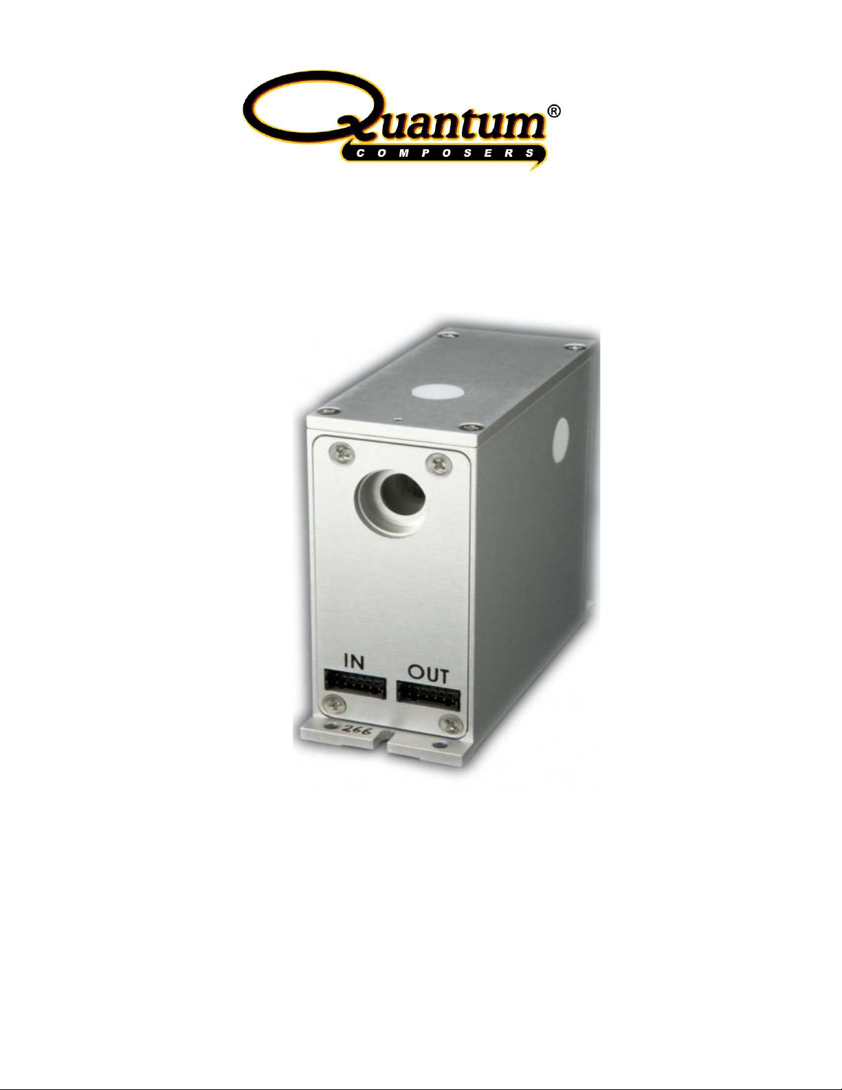
2 Introduction
The Quantum Composers motorized attenuator module provides lineari zed control of
polarized laser energy. The attenuator may be adjusted from 0% to 100% with a shutter
closure to ensure no residual energy at 0% output. Internal calibration, linearization,
and anti-backlash funct ions simplify setup and control. The module is controlled via a
RS232 serial interface that can be daisy chained to other Quantum Composers laser
modules.
3 Setup
The motorized attenuator should be placed such that the laser beam is normal and
center on the input aperture of the attenuator. This will insure optimum extinction ratio.
Connections to the devi ce for basic operation are listed in the electrical connections
section. At a minimum, power (5V and 12V) and RS232 (serial) connections are
required.
Page 3

Pin Number
Type
Description
1
Ground
Power Ground
2
Power input
+5VDC
3
Power input
+12VDC
4
Power input
+12VDC
5
Ground
Power Ground
6
Ground
Power Ground
7
Input
RS232 Receive (from PC or other module)
8
Output
RS232 Transmit (to PC or other module)
8
Output
RS232 Pass-through In (from other module)
9
Input
Analog reserved (do not connect)
10
Ground
RS232 Pass-through ground
11
N/C
No connection
12
Input/Output
Bus sense line (connect between modules)
4 Electrical Connections
The motorized attenuator module requires two input voltages to be applied for
operation:
+5VDC @ 100m A.
+12VDC @ 500mA.
The included power/communications cable includes the minimum connections for
operation. Detailed electrical connections are described in the tables below.
Input Connector (Connector: Hirose #DF11-12DS-2C, Contacts Hirose #DF11-2428SC)
9 Input Analog reserved (do not connect)
10 Ground RS232 Ground
11 N/C No connection
12 Input/Output Bus sense line (connect between modules)
Output Connector (Connector: Hirose #DF11-12DS-2C, Contacts Hirose #DF11-2428SC)
Pin Number Type Description
1 Ground Power Ground
2 Power output +5VDC
3 Power output +12VDC
4 Power output +12VDC
5 Ground Power Ground
6 Ground Power Ground
7 Input RS232 Pass-through Out (to other module)
Page 4

5 Software Operation
A simplified software interface (GUI) is provided to allow for quick setup and operation
of the module.
The software will run on any Windows based computer. Before running the software,
make sure the module has power applied to it and the RS232 communication port is
connected. Once the module is powered and connected, run the software by double
clicking on the executabl e file. When the software first runs, it will ask what serial port
the module is attached to. Select the appropriate port. It will then ask you to select what
attenuator module you are communicating with. See the command set section for
details on what addresses each attenuator type has. If for any reason, the software
cannot detect the module, then an error message will appear. Re-check all connections
if this should occur. The software allows for adjustments of the at t en uat or from 0% to
100% and control of the shutter. You can either enter the parameters or use the
increment decrement butto ns for adjus t me nt .
Page 5

Pin No.
Name
Description
1
DCD
Data Carrier Detect †
2
Rx
RS232 Receive
3
Tx
RS232 Transmit
4
DTR
Data Terminal Ready †
5
Gnd
Ground
6
DSR
Data Set Ready †
7
RTS
Request to Send †
8
CTS
Clear to Send †
9
RI
Ring Indicator †
Field
Description
Prefix
Single semicolon character ";", must precede all commands. All
Address
2 ASCII characters. Each device has a unique address which is
Deliminator
Single colon character “:”, must follow device address.
Command
Commands are specific to each device -- see the following
6 Command Set
The motorized attenuator communicates via a standard RS232 connection. The default
communication settings are 57,600 baud, 8 data bits, even parity and 1 stop bit (57600,
8, E, 1). A typical serial port pin out is shown below. Only the Rx, Tx and Gnd are used
to communicate with the aperture. The included software can be used to operate the
unit over the serial port at the default baud rate of 57,600.
Typical PC Serial Port (DB9)
† denotes signal not used by the module
Device Command Format
All commands use ASCII characters and are composed of the following fields:
<Prefix><Address><Deliminator><Command String>[Parameters]<Terminator>
devices will reset their command input buffer when the prefix is
received.
programmed into its firmware. See the table below for a list of
addresses.
String
sections for the commands that each device supports.
Page 6

Parameters
(optional field) Some commands may have parameters which
immediately follow the command string. Multiple parameters are
Terminator
ASCII carriage return character (decimal value 13). The receiving
Address
Device
A0
A1
355nm attenuator module
A2
532nm attenuator module
A3
1064nm attenuator module
separated by commas.
device does not process any commands until the terminator is
received.
Device Addresses
266nm attenuator module
Command Types
There are two types of commands -- those that set a value or initiate an actions (control
commands), and those that request information (query commands). Each device must
respond in the proper manner to each type of command.
Control Commands
A device must always parse a control command and return a response immediately.
• If the command is a recognized command and the parameter is valid, then the
device returns an " OK<CR>". (<CR> = ASCII carriage return, decimal value 13).
• If the command is not recognized by the device, then it responds with "?1<CR>
• If the command is recognized, but the parameter value is missing or invalid, then the
device responds with a "?2<CR>".
• If the comm and is recognized, but the parameter is out of range, then the device
responds with a “?3<CR>”.
If a control command is received while the device is in the midst of executing a previous
command, and the commands are mutually exclusive (cannot be executed in parallel),
then the previous command is aborted and the new one executed. It is up to the host
controller (the PC) to poll the device and make sure the previous command is finished, if
that is the needed.
Query Commands
Query commands return a value to the PC as soon as the command is parsed and
executed. The value returned will depend on the command. The response is always
Page 7

terminated with a <CR>. If a query command is not recognized by the device, then a
Command
Description
VN
Return firmware versi on
Command
Description
*RS
Reset, return to power-up
"?0" is returned.
Common Commands
All devices are required to support some common commands as part of their command
set. Those commands are:
number
RS Reset, return to power-up
defaults.
Global Commands
By using a special prefix (the * character), it is possible to send a command to all the
devices at once. When a global command is sent, no device will send a response.
defaults. All devices
Command Set
AP #### Set to attenuator to percentage of max. Parameter = 4-digit hex
value 0000h – 03E8h (0 to 1000). 0000 closes the shutter, any
other value opens the shutter .
AP? Returns the current attenuator position in a 4 digit hex value from
0000h to 03E8h.
EC # Echo characters received on the serial port. Parameter (0 = echo
off (default), 1 = echo on.
EC? Returns the state of the echo parameters.
HM Home Motor. Moves motors to limits, then returns to default
position.
RS Resets all motors, returns to power up defaults and homes the
motors
SH # Shutter Open / Shutter Closed (1 = close shutter, 0 = open shutter).
Page 8

SH? Returns the current shutter state.
7 6 5 4 3 2 1
0
Fault
Shutter
Limit A
Fault
0
Homing
Busy
M Busy
SS? System Status. Returns status of system as 2-digit ASCII hex
value. Note that M (modules) Busy indicates that some mo dul e on
the serial bus is busy. This allows one poll to determine if any of
the modules are busy.
VN Version Number. Returns the firmware revision number as a 4-
digits in the format “m.nn”, where m = major version, n = minor
version.
7 Specifications
Input
Wavelength 266nm, 355nm, 532nm, or 1064nm (must be specified)
Polarization Vertical (horizontal may be used, attenuation reversed)
Beam Height 60mm (other configurations upon request)
Fluence 2 J/cm2 max
Diameter 6.35mm max
Output
Direction Colliner, 180 degrees to input
Displacement 0 deg, collinear
Polarization Linear, S polarized
Tmax 266 nm = 95%
355 nm = 85%
532 nm = 75%
1064 nm = 70%
Page 9

Extinction Ratio 22dB min (150:1) min
Purity Residual Energy < 0.25%
Range 0 to Tmax, linearized, normalized
Resolution 0.2% nominal
Tact Time < 1.0s full range of travel
Controller
Comm RS232, w/ bypass output which allows multiply units to be
daisy chained on the same serial port.
Baud Rate 57,600, 8, E, 1 (other speeds availabl e on request)
Range 0 to 100%
Resolution 0.1%
Tact Time < 1s, full range motion
Mechanical
Please contact the factory for details and drawings.
 Loading...