

Page 1

LTO Standalone User’s Guide
LTO 200D and LTO 400D
Page 2

Copyright Notice
© 2003 ADIC
The information contained in this document is subject to change without notice.
This document contains proprietary information which is protected by copyright. All rights are reserved. No part of this
document may be photocopied, reproduced, or translated to another language without prior written consent of ADIC.
ADIC shall not be liable for errors contained herein or for incidental or consequential damages (including lost profits) in
connection with the furnishing, performance or use of this material whether based on warranty, contract, or other legal theory.
All trademarks within this document are the property of their respective owners.
Copyright Notice (Europe)
© 2003 ADIC Europe
All rights reserved. No part of this document may be copied or reproduced in any form or by any means, without prior
written permission of ADIC Europe, ZAC des Basses Auges, 1 rue Alfred de Vigny, 78112 Fourqueux, France.
ADIC Europe assumes no responsibility for any errors that may appear in this document, and retains the right to make
changes to these specifications and descriptions at any time, without notice.
This publication may describe designs for which patents are pending, or have been granted. By publishing this information,
ADIC Europe conveys no license under any patent or any other right.
ADIC Europe makes no representation or warranty with respect to the contents of this document and specifically disclaims
any implied warranties of merchantability or fitness for any particular purpose. Further, ADIC Europe reserves the right to
revise or change this publication without obligation on the part of ADIC Europe to notify any person or organization of such
revision of change.
Every effort has been made to acknowledge trademarks and their owners. Trademarked names are used solely for
identification or exemplary purposes, any omission are made unintentionally.
ADIC is a registered trademark and ADIC Europe is a trademark of Advanced Digital Information Corporation.
ADIC USA
Tel.: +1 303-705-3900
Fax: +1-303-792-2465
ATAC: 1-800-827-3822
http://www.adic.com
TM
ADIC Europe
ZAC des Basses Auges
1, rue Alfred de Vigny
78112 Fourqueux, France
Tel.: +33.1.3087.5300
ADIC Germany Beteiligungs
GmbH, KG
Eschenstraße 3
D-89558 Böhmenkirch, Germany
Tel:+00.800.9999.3822
Fax: +33.1.3087.5301
Published: May 2003 Printed in the USA
Part Number: 6-00709-01 Rev A
ADIC CORPORATE • 11431 WILLOWS ROAD, NE • REDMOND, WASHINGTON, USA • 1-800-336-1233
ADIC • 8560 UPLAND DRIVE • ENGLEWOOD, COLORADO, USA • 1-800-827-3822
ADIC • 10 BROWN ROAD • ITHACA, NEW YORK, USA • 1-607-241-4800
ii
Page 3

Regulatory Notices
ADIC libraries are designed, tested, and classified for their intended electromagnetic environment. These electromagnetic environment
classifications generally refer to the following harmonized definitions:
Class A is typically for business or industrial environments.
Class B is typically for residential environments.
To determine which classification (Class A or B) applies to your tape library, examine all registration labels located on the bottom, the back
panel, or on the inside of the chassis below the magazines.
FCC Notices (USA Only)
To determine which classification applies to your library, examine all FCC registration labels located on the bottom or back panel of your
library or on installable components. If any one of the labels carries a Class A rating, your entire system is considered to be a Class A
digital device. If all labels carry either the Class B rating distinguished by either an FCC ID number or the FCC logo, (
considered to be a Class B digital device.
Once you have determined your system’s FCC classification, read the appropriate FCC notice. Note that FCC regulations provide that
changes or modifications not expressly approved by ADIC could void your authority to operate this equipment.
This device complies with Part 15 of the FCC Rules. Operation is subject to the following two conditions:
This device may not cause harmful interference.
This device must accept any interference received, including interference that may cause undesired operation.
), your system is
Note
Use only shielded cables for connecting peripherals to this device to reduce the possibility of interference with radio and television
reception. Using shielded cables ensures that you maintain the appropriate FCC radio frequency emissions compliance (for a Class
A device) or FCC Certification (for a Class A device) of this product.
The following information is provided on the device or devices covered in this document in compliance with FCC regulations:
Product Name: LTO 200D or LTO 400D
Model number: LTO 200D or LTO 400D
Company name: Advanced Digital Information Corporation
PO Box 97057
Redmond, WA 98073-9757 USA
(425) 881-8004
Class A
This equipment has been tested and found to comply with the limits for a Class A digital device pursuant to Part 15 of the FCC
Rules. These limits are designed to provide reasonable protection against harmful interference when the equipment is operated in
a commercial environment. This equipment generates, uses, and can radiate radio frequency energy and, if not installed and used
in accordance with the manufacturer’s instruction manual, may cause harmful interference with radio communicatio ns.
Operation of this equipment in a residential area is likely to cause harmful interference, in which case you will be required to
correct the interference at your own expense.
Class B
This equipment has been tested and found to comply with the limits for a Class B digital device pursuant to Part 15 of the FCC
Rules. These limits are designed to provide reasonable protection against harmful interference in a residential installation. This
equipment generates, uses, and can radiate radio frequency energy and, if not installed and used in accordance with the
manufacturer’s instruction manual, may cause interference with radio communications. However, there is no guarantee that
interference will not occur in a particular installation.
iii
Page 4

If this equipment does cause harmful interference to radio or television reception, which can be determined by turning the
equipment off and on, you are encouraged to try to correct the interference by one or more of the following measures:
Reorient or relocate the receiving antenna.
Increase the separation between the equipment and the receiver.
Connect the equipment into an outlet on a circuit different from that to which the receiver is connected.
Consult the dealer or an experienced radio/television technician for help.
IC Notice (Canada Only)
Most tape devices are classified by the Industry Canada (IC) Interference-Causing Equipment Standard #3 (ICES-003) as Class B digital
devices. To determine which classification (Class A or B) applies to your tape device, examine all registration labels located on the bottom
or the back panel of your device. A statement in the form of “IC Class A ICES-3” or “IC Class B ICES-3” will be located on one of these
labels.
Note that Industry Canada regulations provide that changes or modifications not expressly approved by the tape device manufacturer could
void your authority to operate this equipment.
This Class B (or Class A, if so indicated on the registration label) digital apparatus meets the requirements of the Canadian
Interference-Causing Equipment Regulations.
Cet appareil numérique de la Classe B (ou Classe A, si ainsi indiqué sur l’étiquette d’enregistration) respecte toutes les exigences du
Reglement sur le Materiel Brouilleur du Canada.
EN 55022 Compliance (Czech Republic Only)
This device belongs to category B devices as described in EN 55022, unless it is specifically stated that it is a category A device on the
specification label. The following applies to devices in category A of EN 55022 (radius of protection up to 30 meters). The user of the
device is obliged to take all steps necessary to remove sources of interference to telecommunication or other devices.
CE Notice
Marking by the symbol indicates compliance of this device to the EMC (Electromagnetic Compatibility) directive of the European
Community. Such marking is indicative that this tape library meets or exceeds the following technical standards:
EN 55022 – “Limits and Methods of Measurements of Radio Interference Characteristics of Information Technology Equipment.” This
system is EN 55022 Class B device (CISPR 22).
EN 50081-1 – “Electromagnetic compatibility – Generic emission standard Part 1: Residential, commercial and light industry.”
EN 55024:1998 – Information technology equipment – Immunity characteristics – Limits and methods of measurements.
IEC 60950:1991+A1/A2/A3/A4 – “Safety of Information Technology Equipment including Electrical Business Equipment”.
Declaration of Conformity
The signed Declaration of Conformity is on file with Advanced Digital Information Corporation, 17275 NE 67th Court, Redmond,
Washington 98052, and ADIC Europe, ZAC des Basses Auges 1, rue Alfred de Vigny, 78112 Fourqueux,
iv
Page 5

R
A
A
A
A
A
Safety Notices
Warnings
CAUTION
ISK OF ELECTRIC SHOCK
DO NOT OPEN
This symbol should alert the
user to the presence of
"dangerous voltage" inside
the product that might cause
harm or electric shock.
UTION :
C
THERISKOFELECTRIC
SHOCK, DO NOT REMOVE
COVER (OR B
NO USER-SERVICE
RTS INSIDE. REFER
P
SERVICING TO QU
SERVICE PERSONNEL.
TO REDUCE
CK).
BLE
LIFIED
Caution
All safety and operating instructions must be read before this product is
operated, and must be retained for future reference. This unit has been
engineered and manufactured to assure your personal safety. Improper use can
result in potential electrical shock or fire hazards. To maintain the safeguards,
observe the following basic rules for its installation, use and servicing.
Follow all Warnings–All warnings on the product and in the operating instructions should be followed.
Read Instructions–All operating and use instructions should be read and followed.
Ventilation–The product should be situated so that its location or position does not interfere with proper ventilation.
Heat–The product should be situated away from heat sources such as radiators, heat registers, furnaces, or other heat producing
appliances.
Power Sources–The product should be connected to a power source only of the type directed in the operating instructions or as marked
on the product.
Power Cord Protection–The AC line cord should be routed so that it is not likely to be walked on or pinched by items placed upon or
against it, paying particular attention to the cord at the wall receptacle, and the point where the cord exits from the product.
Object and Liquid Entry–Care should be taken to insure that objects do not fall and liquids are not spilled into the product’s enclosure
through openings.
Servicing–The user should not attempt to service the product beyond that described in the operating instructions. All other servicing
should be referred to qualified service personnel.
Precautions
Do not use oil, solvents, gasoline, paint thinners or insecticides on the unit.
Do not expose the unit to moisture, to temperatures higher than 60ºC (140ºF) or to extreme low temperatures.
Keep the unit away from direct sunlight, strong magnetic fields, excessive dust, humidity and electronic/electrical equipment, which
generate electrical noise.
Hold the AC power plug by the head when removing it from the AC source outlet; pulling the cord can damage the internal wires.
Use the unit on a firm level surface free from vibration, and do not place anything on top of unit.
v
Page 6

Blank Page
vi
Page 7

Table of Contents
Copyright Notice............................................................................................................................................... ii
Regulatory Notices .......................................................................................................................................... iii
FCC Notices (USA Only) ........................................................................................................................ iii
Class A............................................................................................................................................... iii
Class B............................................................................................................................................... iii
IC Notice (Canada Only) ..........................................................................................................................iv
EN 55022 Compliance (Czech Republic Only) ........................................................................................iv
CE Notice..................................................................................................................................................iv
Declaration of Conformity........................................................................................................................iv
Safety Notices....................................................................................................................................................v
Warnings....................................................................................................................................................v
Precautions.................................................................................................................................................v
Table of Contents............................................................................................................................................ vii
List of Figures...................................................................................................................................................ix
List of Tables ....................................................................................................................................................xi
Introduction ...............................................................................................................................................................1
Equipment Description ......................................................................................................................................2
Drive Technology and Capacity.................................................................................................................2
Options.......................................................................................................................................................2
SCSI Interface......................................................................................................................................2
Front Panel Controls and Indicators...........................................................................................................3
Rear Panel Controls and Connectors..........................................................................................................5
LTO Tape Cartridges .................................................................................................................................5
Environmental and Shipping Information............................................................................................ 5
Write-Protect Switch............................................................................................................................6
Handling the Cartridges .......................................................................................................................7
Other Requirements ...................................................................................................................................7
SCSI Host Adapter...............................................................................................................................7
Application Software ...........................................................................................................................7
Installation .................................................................................................................................................................9
Installing the Host Adapter ..............................................................................................................................10
Connecting the Interface Cable........................................................................................................................10
Connecting More than One LTO Standalone Unit...........................................................................................10
Setting the SCSI ID..........................................................................................................................................12
Check the SCSI Bus Termination ....................................................................................................................13
Connecting Power and Turning the Autoloader On .........................................................................................13
Installing the Host Software.............................................................................................................................13
Operation and Maintenance.....................................................................................................................................15
Drive Status..............................................................................................................................................16
LCD Messages...................................................................................................................................16
LED Indicators...................................................................................................................................17
Normal Drive Operating Conditions........................................................................................................18
LCD Messages...................................................................................................................................18
Loading the Tape Cartridge .............................................................................................................................18
Data Protection ........................................................................................................................................20
Removing the Data Cartridge ..........................................................................................................................20
Cleaning the Drive Head..................................................................................................................................21
Cleaning the Enclosure ....................................................................................................................................21
Troubleshooting and Diagnostics.............................................................................................................................23
Troubleshooting Chart ..................................................................................................................................... 24
Maintenance Mode ..........................................................................................................................................25
Putting the LTO Standalone in Maintenance Mode...........................................................................26
Diagnostic or Maintenance Functions......................................................................................................26
Exit Maintenance Mode.....................................................................................................................27
vii
Page 8

Drive R/W Diagnostic........................................................................................................................27
Update Drive Firmware from FMR Tape...........................................................................................29
Create FMR Tape...............................................................................................................................31
Force a Drive Dump...........................................................................................................................33
Copy the Drive Dump to Tape [at Beginning of Tape (BOT)] ..........................................................34
SCSI Wrap Test Function .................................................................................................................. 36
Unmake FMR Tape............................................................................................................................37
Display Error Code Log.....................................................................................................................39
Clear Error Log..................................................................................................................................40
Test Cartridge and Media...................................................................................................................40
Fast R/W Diagnostic..........................................................................................................................42
Test Head...........................................................................................................................................44
Error Codes and Messages.......................................................................................................................46
Code...................................................................................................................................................46
Specifications...........................................................................................................................................................49
Index........................................................................................................................................................................51
viii
Page 9

List of Figures
Figure 1-1 LTO Standalone Front Panel........................................................................................................................................................... 3
Figure 1-2 LTO Standalone Rear Panel............................................................................................................................................................ 5
Figure 1-3 LT0 Data Cartridge .........................................................................................................................................................................6
Figure 2-1 Cable Diagram for Four LTO Standalone Units............................................................................................................................ 11
Figure 2-2 SCSI ID Switch............................................................................................................................................................................. 12
Figure 3-1 Loading a Data Cartridge.............................................................................................................................................................. 19
ix
Page 10

Blank Page
x
Page 11

List of Tables
Table 1-1 Front Panel Controls and Indicators ................................................................................................................................................. 4
Table 1-2 Rear Panel Controls and Connectors ................................................................................................................................................ 5
Table 1-3 Recommended Operating, Storing, and Shipping Environment .......................................................................................................6
Table 3-1 POST LCD Messages..................................................................................................................................................................... 16
Table 3-2 Status LED States........................................................................................................................................................................... 17
Table 3-3 Normal Operating Condition LCD Messages................................................................................................................................. 18
Table 4-1 Troubleshooting Chart.................................................................................................................................................................... 24
Table 4-2 Error Codes and Messages..............................................................................................................................................................46
xi
Page 12

Blank Page
xii
Page 13

Chapter
Introduction
This Chapter. . .
❐ provides a physical description of the switches, indicators and connectors on the front and rear
panels of the LTO standalone.
❐ describes other requirements (additional hardware and software) needed to use the LTO
standalone device.
1
Page 14

Equipment Description
The LTO standalone is a SCSI-compatible, high performance, tape cartridge device designed for storage of near-line and off-line data.
The LTO standalone is equipped with a 2-line by 20-character, back-lit LCD display (LCD). The LCD displays drive status messages, error
messages, and drive Power-On Self-Test (POST) result messages. The LTO standalone uses a 7-segment single-character LED (singlecharacter display) to communicate error conditions and informational messages. The LTO standalone also includes Flash EEPROM
technology that allows you to easily update firmware onsite from tape or from the host.
Drive Technology and Capacity
Your LTO standalone is equipped with one of the following drives:
LTO 200D
o Contains an IBM® TotalStorage™ Linear Tape Open (LTO) Ultrium 1 tape drive
o When used with generation 1 tape cartridges, the native capacity is 100 GB (200 GB compressed, assuming 2:1
compression).
LTO 400D
o Contains an IBM® TotalStorage™ LTO Ultrium 2 tape drive
o When used with generation 2 tape cartridges, the native capacity is 200 GB (400 GB compressed, assuming 2:1
compression).
Options
SCSI Interface
The LTO standalone is available with either an Ultra-2 or Ultra-3, Low Voltage Differential/Single Ended (LVD/SE) SCSI interface, or an
Ultra-2, High-Voltage Differential (HVD) SCSI interface. The LTO 200D uses Ultra-2 and is available either with LVD/SE or HVD SCSI
connections. The LTO 400D uses Ultra-3 and is only available with LVD/SE connections.
Caution
Single-Ended (SE) and LVD/SE SCSI devices are not compatible with HVD
SCSI devices. Equipment damage may occur if you connect your LTO
standalone to an incompatible SCSI bus.
2 Introduction
Page 15

Front Panel Controls and Indicators
Figure 1-1 shows the controls and indicators located on the front panel of the LTO standalone. Table 1-1 provides a brief functional
description of the front panel controls and indicators.
LCD
Single-character display
Status LED
Single Red Dot
(400D only)
Figure 1-1 LTO Standalone Front Panel
Unload Button
Introduction 3
Page 16

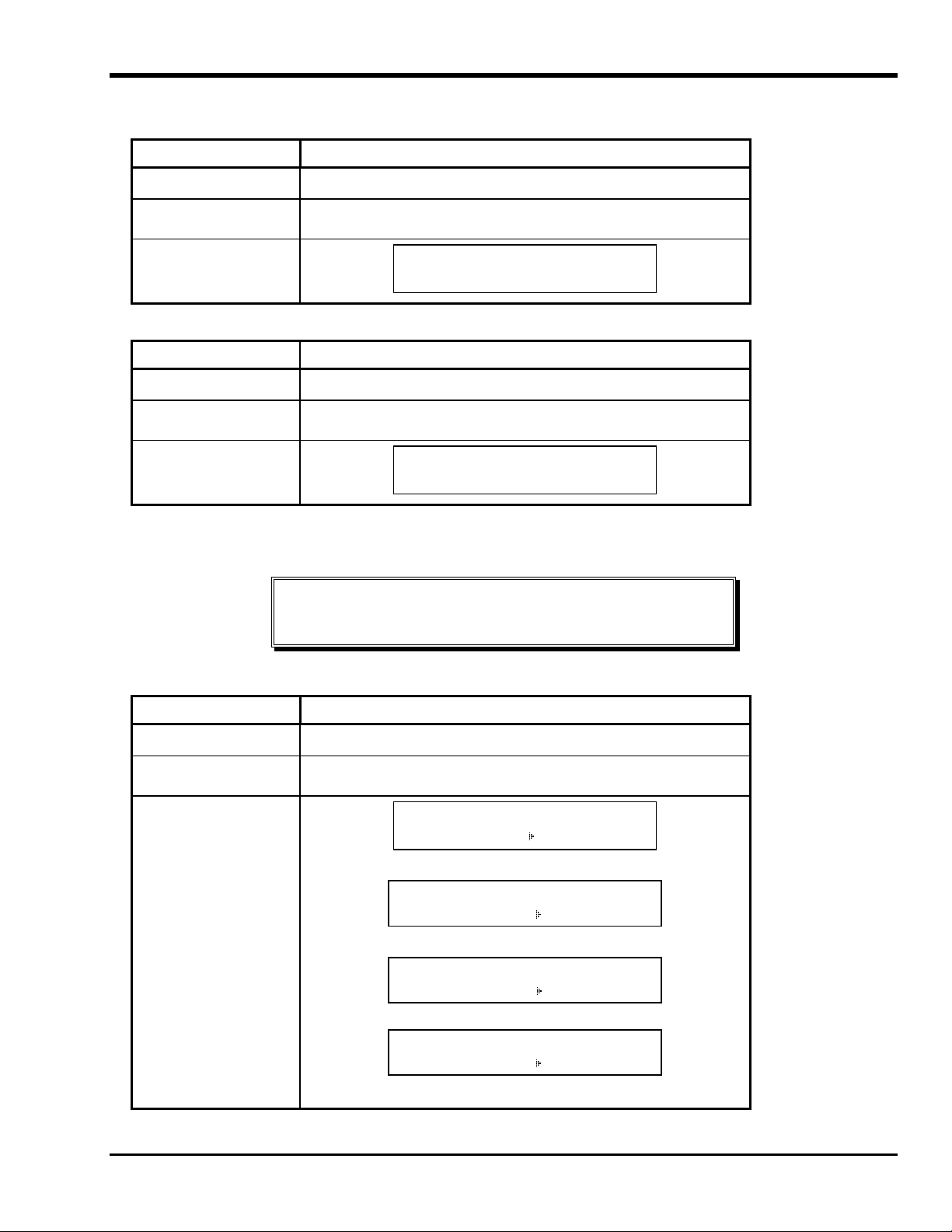
Table 1-1 Front Panel Controls and Indicators
Control or Indicator Purpose
LCD
Status LED
(green/amber)
2-line by 20-character LCD. Displays drive status, error messages, and POST results.
Provides information about the state of the drive. The Status LED is either green or
amber, and can be solid or flashing (refer to Table 3-2 in Chapter 3 Operation and
Maintenance for a description of the Status LED states).
Single-Character
Display
Single Red Dot
Unload Button
Blank (off) during normal operation, the single-character display presents a singlecharacter code for:
Diagnostic or maintenance functions
Error conditions and informational messages
(LTO 400D only) The Single Red dot is located on the single-character display. When
it is on, the drive has created a dump. For information on copying the dump to a tape,
see Maintenance Mode.
The Unload button enables you to perform several functions.
Press the Unload button once to start a manual unload of the tape.
Note
During a rewind and eject operation, your LTO standalone will not accept
SCSI commands from your host.
Press the Unload button three times within one second to place your LTO standalone
in Maintenance Mode (refer to Chapter 4 Troubleshooting and Diagnostics for a
description of Maintenance Mode functions and a description of the functions the
Unload button can perform while in this mode).
Note
While in Maintenance Mode, your LTO standalone will not accept SCSI
commands from your host.
Press and hold the Unload button for 10 seconds while your LTO standalone is in
normal operating mode, to force a drive dump (save a microcode trace). The drive
places the dump data into a special dump area where it is retrievable (refer to Chapter
4 Troubleshooting and Diagnostics for a description of the Force Drive Dump
function and information about retrieving the data.).
Note
After you force a drive dump, do not turn off power to your LTO
standalone or you may lose the dump data.
4 Introduction
Page 17

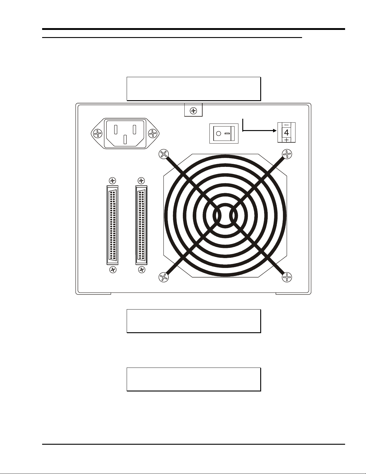
Rear Panel Controls and Connectors
Figure 1-2 shows the controls and connectors located on the rear panel of the LTO standalone.
SCSI ID Switch
AC Power Connector
SCSI Connectors
Power Switch
Figure 1-2 LTO Standalone Rear Panel
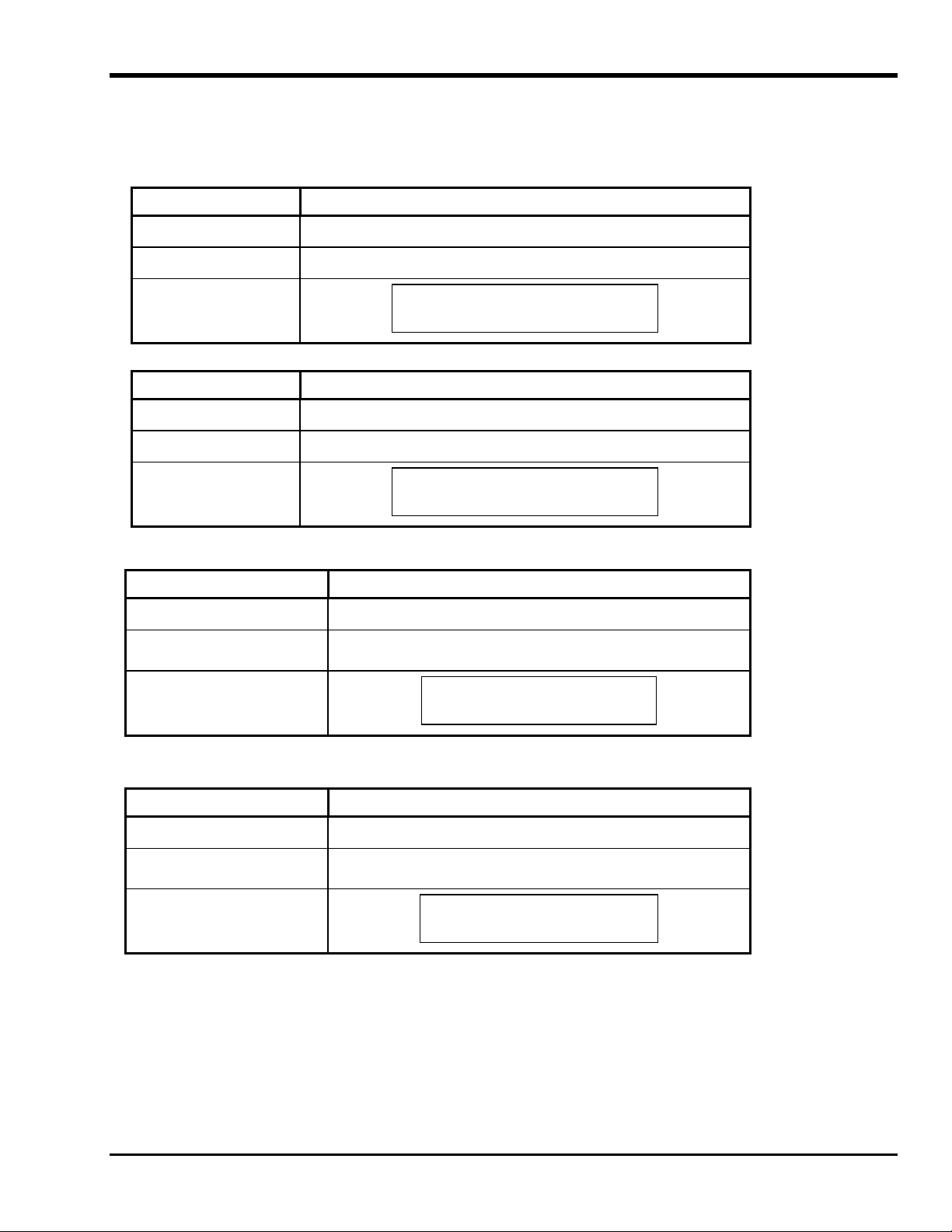
Table 1-2 Rear Panel Controls and Connectors
Control or Connector Purpose
Power Switch
AC Power Connector
SCSI Connectors
SCSI ID Switch
Turns power to the unit on and off.
Receptacle for AC power cord.
Connections for the interface cable that connects the unit with the host computer
and/or to other devices on the SCSI channel. The interface cable can be attached
to either connector.
Your LTO standalone is equipped with a 68-pin high density SCSI device
connector.
Used to select the SCSI ID for the LTO drive. Factory set at 0.
LTO Tape Cartridges
To ensure that your LTO standalone conforms to ADIC specifications for reliability, use industry-approved LTO Ultrium tape cartridges.
Other certified LTO Ultrium data cartridges supported by your LTO standalone include: 10GB, 30GB, and 50GB.
Environmental and Shipping Information
Whenever possible, store LTO Ultrium Tape Cartridges in the following room-environment conditions:
Temperature of 20°C, to 5°C (68°F, to 9°F)
Relative humidity of 50% (20%)
Introduction 5
Page 18

The best storage container for unused cartridges is the original shipping container. The plastic wrapping prevents dirt from accumulating on
the cartridges and partially protects them from humidity changes.
You can store tape cartridges in the maximum environmental conditions for up to four weeks without damaging the data or the cartridge.
Do not store cartridges for an extended time period in maximum temperature and humidity conditions.
When you ship a cartridge, place it in a sealed, moisture-proof bag to protect it from moisture, contaminants, and physical damage. Ship the
cartridge in a shipping container that has enough packing material to cushion the cartridge and prevent it from moving within the container.
Table 1-3 lists the recommended environment for operating, storing, and shipping LTO Ultrium data cartridges.
Table 1-3 Recommended Operating, Storing, and Shipping Environment
Environmental
Operating Storage Shipping
Factor
Temperature 10°C to 40°C
(50°F to 104°F)
Relative humidity
(noncondensing)
Wet bulb temperature 26°C
20% to 80% 20% to 80% 20% to 80%
(79°F)
Figure 1-3 LT0 Data Cartridge
16°C to 32°C
(61°F to 90°F)
26°C
(79°F)
-23°C to 49°C
(-9°F to 120°F)
26°C
(79°F)
Write-Protect Switch
Write-Protect Switch
The write-protect switch is used to prevent recording over existing data. To prevent recording or deleting, set the write-protect switch to the
closed position ( ). The drive senses the position of the switch and will not allow writing in this position. When installing cartridges in
your LTO standalone, place the switch in the open position (
protect switch, slide it left or right to the desired position.
If the switch is set to
If the switch is set to
6 Introduction
data cannot be written to the tape.
data can be written to and read from the tape.
Always remove any cartridge from the drive before turning off the host system
power. Failure to remove a cartridge can result in cartridge and drive damage.
When a cartridge is removed from the drive, return it to the plastic case to
prolong the cartridge life.
), unless you do not wish to record on a specific cartridge. To set the write-
Cautions
Page 19

Handling the Cartridges
Incorrect handling or an incorrect environment can damage the magnetic tape or the cartridges. To avoid damage to your tape cartridge and
to ensure the continued high reliability of your LTO standalone, pay attention to the following guidelines.
Before using a cartridge, let it acclimate to the normal operating environment for at least 24 hours.
Ensure that all surfaces of a cartridge are dry before inserting it into drive.
Do not insert a damaged cartridge into the drive. A damaged cartridge can interfere with the reliability of the drive. Before
inserting a cartridge, inspect the cartridge case, cartridge door, and write-protect switch for cracks and breaks. If you need to
recover data from a damaged cartridge, call your service representative.
Do not open the cartridge case at any time. The upper and lower parts of the case are welded; separating them destroys the
usefulness of the cartridge.
Do not handle tape that is outside the cartridge. Handling the tape can damage the tape surface or edges, which may interfere with
read or write reliability. Pulling on tape that is outside the cartridge case can damage the tape and the brake mechanism in the
cartridge.
Do not stack more than six cartridges. Although cartridges are shipped and should be stored with the reel in the vertical position,
you can temporarily lay the cartridges flat when moving them. The bottom of each cartridge has four raised areas that fit into the
indented areas on the top of another cartridge. This construction helps prevent the cartridges from sliding while you move them.
Do not expose the cartridge to moisture or direct sunlight.
Do not expose recorded or blank tape cartridges to stray magnetic fields greater than 100 oersteds (such as those existing near
high-current cables or power supplies). Such exposure can cause loss of recorded data or make the blank cartridge unusable.
Other Requirements
SCSI Host Adapter
Your LTO standalone must be connected to either an integrated SCSI host or a separate SCSI interface (host adapter) card installed in the
computer–either directly to the I/O connector on the card or as part of an existing SCSI bus. The host adapter you choose must support the
same SCSI interface as your LTO standalone (LVD/SE or HVD). The need for additional host adapter features will depend on your host
system requirements. If you are not sure about your host adapter requirements, please call the ADIC Technical Assistance Center (ATAC)
and ask for assistance.
Caution
SE and LVD/SE SCSI devices are not compatible with HVD SCSI devices.
Equipment damage may occur if you connect your ADIC LTO standalone to an
incompatible SCSI bus.
Note
In the United States and Canada, call ATAC at (800) 827-3822. In
Europe, call ATAC at +800.9999.3822.
Application Software
A variety of backup and data storage software is available for use with your LTO standalone. The software you use will depend upon your
storage needs and the system you are using. Please check with ADIC Sales or Customer Assistance if you have a question concerning the
compatibility of a particular software package.
Now you are ready to connect the LTO standalone to your host computer. Follow the instructions provided in the next chapter.
Introduction 7
Page 20

Blank Page
8 Introduction
Page 21

Chapter
Installation
This Chapter. . .
❐ Explains the steps necessary to install and test the LTO standalone devices.
❐ Provides a ✔symbol next to each step verified as correct.
9
Page 22

Unpacking and Inspecting
Caution
If the operating environment differs from the storage environment by 15°C
(30°F) or more, let the unit acclimate to the surrounding environment for at
least 12 hours.
Unpack all items from the carton. Save the packing materials in case you need to move or ship the system in the future.
Caution
You must ship the LTO standalone in the original or equivalent packing
materials or your warranty may be invalidated.
Installing the Host Adapter
At this point if your host computer system does not have native SCSI capability and the host adapter you are using is not installed, please
install it. Refer to the manual that came with your host adapter for specific directions.
When the host adapter card is installed, return to this point in the manual.
Connecting the Interface Cable
Attach an interface cable between the host adapter and the LTO standalone. The type of cable needed depends on the type of SCSI bus
connector on the host adapter. The LTO standalone has two SCSI device connectors on the rear panel. It does not matter which connector is
used.
Note
The jackscrews at the ends of the SCSI cable must be securely
fastened to ensure communications between the LTO standalone
and the host computer.
✔ Make sure that the SCSI cable between the host adapter and the LTO standalone is secure and the connections are fastened
correctly.
Connecting More than One LTO Standalone Unit
If connecting to more than one LTO standalone unit on the same SCSI bus, connect each unit to the previous unit with an interface cable.
The connection sequence between the units is not critical. Refer to Figure 2-1 on the following page to see a configuration setup.
Note
Don’t forget to install the SCSI terminator on the last device in the
chain.
10 Installation
Page 23
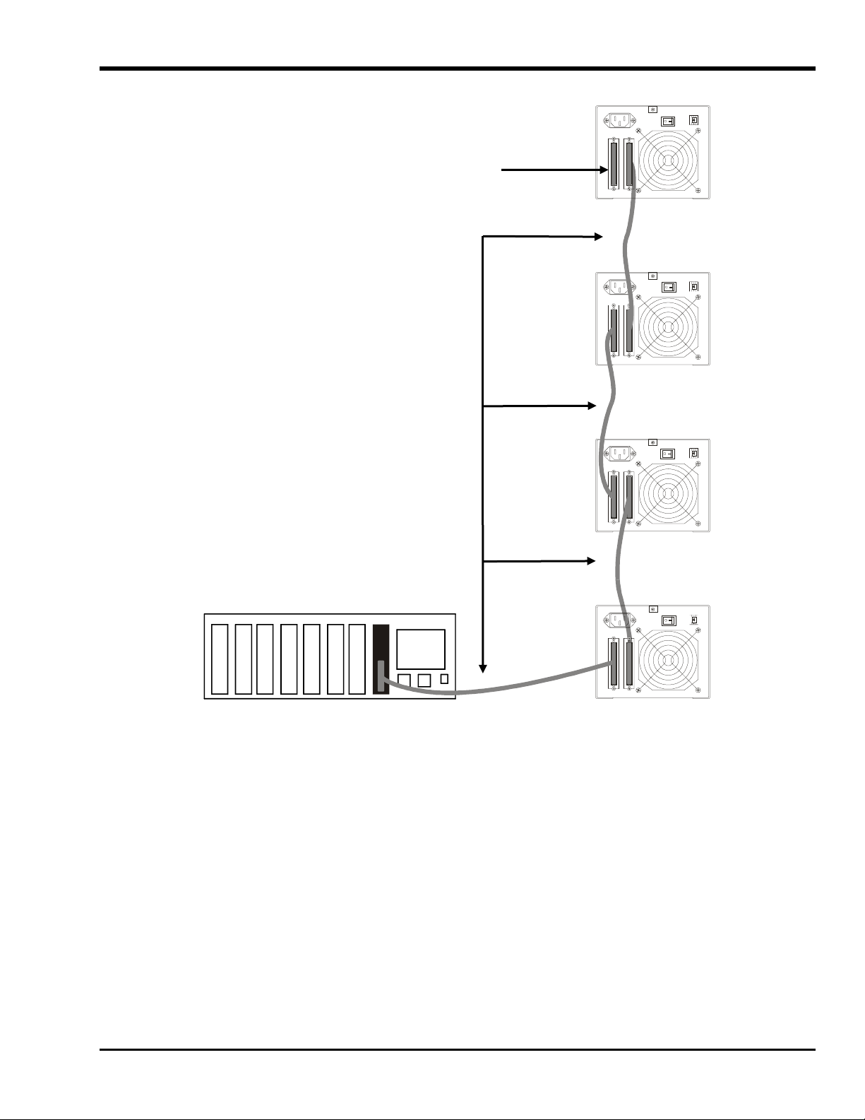
SCSI Terminator
SCSI Cables
Unit 4 SCSI ID 3
Unit 3 SCSI ID 2
Unit 2 - SCSI ID 1
Host Computer
Figure 2-1 Cable Diagram for Four LTO Standalone Units
Unit 1 - SCSI ID 0
Installation 11
Page 24
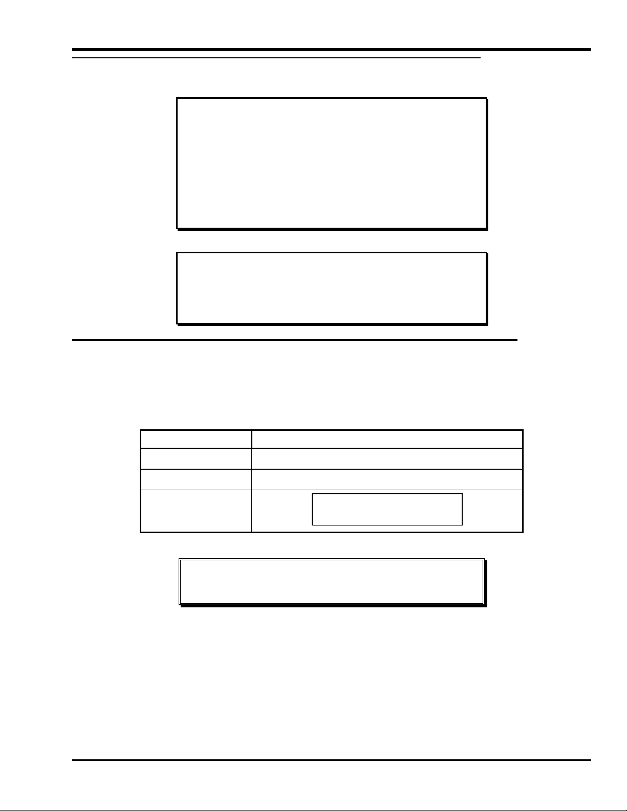
Setting the SCSI ID
The SCSI ID of the LTO standalone may need to be changed, depending upon factors in the setup, operating system, and number of SCSI
devices on the bus. Each device on the bus must have its own address. See Figure 2-2.
Notes
The SCSI ID has been factory preset to 0.
All devices on a SCSI bus must be set to a unique ID.
SCSI ID Switch
Figure 2-2 SCSI ID Switch
Note
The LTO standalone can be set to any SCSI ID between 0 and
15.
The SCSI ID switch is located on the rear of the LTO standalone (see Figure 2-2). Use a small pointed object to press either the + button on
the bottom, or the minus button on the top of the switch to select the proper ID.
Count the SCSI ID on each device in order from 0 to 15 on each SCSI bus to confirm that no two devices have the same ID number
assigned.
Note
The SCSI Host Adapter is normally set to SCSI ID 7, so this ID is
usually not available for a device.
12 Installation
Page 25

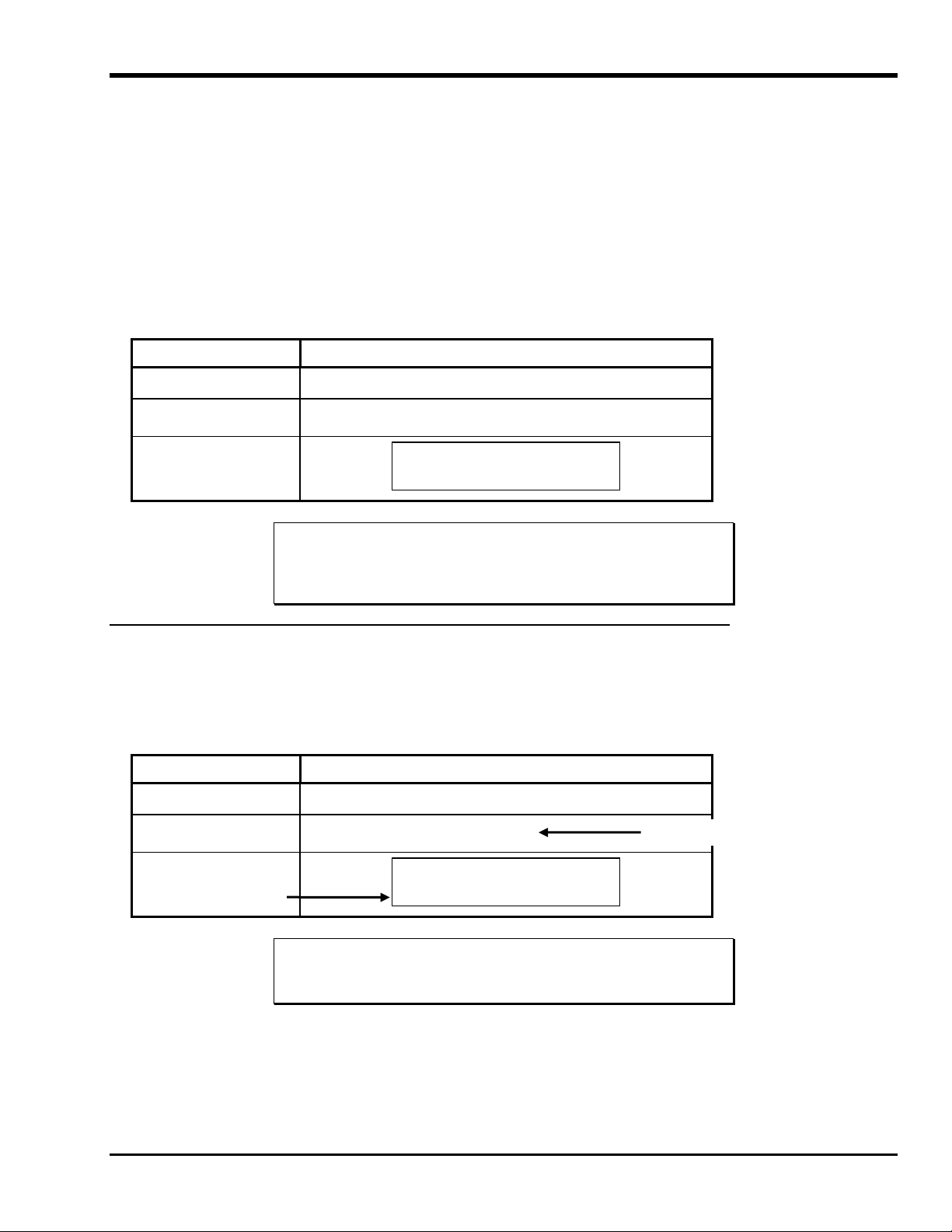
Check the SCSI Bus Termination
SCSI buses require termination at each end for proper operation. A typical external subsystem installation would be terminated at the SCSI
host adapter and at the last device in the chain.
If an external device is being used with an internal device (on the same channel), the SCSI host adapter would now be in the middle of the
bus rather than at the end. In this case, the termination would be at the internal device and at the last drive in the external chain. Remove the
terminators on the SCSI host adapter. Refer to the SCSI host adapter manual for directions on removing the terminators on the board.
Connecting Power and Turning the Autoloader On
1. Plug the power cord into the back of the LTO standalone.
2. Plug the power cord from the LTO standalone into a GROUNDED electrical outlet.
3. Plug the power cord from the host system into the same GROUNDED electrical circuit if possible. Computers and peripherals
should always share the same grounds.
4. Turn power on.
5. After the LTO standalone completes its Power on Self Test (POST), turn on the power to the host system.
Installing the Host Software
Refer to the host software installation guide and install the software, if necessary.
After completing installation of the LTO standalone unit and the host software, run a small backup/restore test and compare the results to
confirm that the unit is working correctly. Refer to the software installation guide for additional information.
Installation 13
Page 26

Blank Page
14 Installation
Page 27

Chapter
Operation and Maintenance
This Chapter . . .
❐ describes normal operating features of the LTO standalone.
❐ explains how, and when to clean the tape head.
❐ describes how to clean the enclosure.
15
Page 28

Power-on Self-Test and Initialization
When the system power is turned on, the drive performs a Power-on Self-Test (POST) and initialization. POST is completed in
approximately three minutes and the drive will respond normally to all commands. However, it may take longer for the media to be ready.
Following POST completion, the Status LED will be solid green.
Drive Status
LCD Messages
Table 3-1 describes the messages displayed on the LCD during and immediately after the POST:
Table 3-1 POST LCD Messages
Drive State
POST is executing.
POST completed and no cartridge is
present.
POST completed and a cartridge is
present.
The drive detects an error condition.
Message
Power On Self Test
In Progress
Will be displayed for several minutes, followed by:
Drive FW X.X.X
Display FW X.X.X
“DRIVE FW” is the firmware version of the drive.
“DISPLAY FW” is the firmware version of the LCD controller.
Ultrium Tape Drive
Drive Empty
Volume Loaded DC WP
Ready...
“DC” indicates that drive data compression is enabled
“WP” indicates that cartridge is write-protected.
Error!
Selftest Failure
16 Operation and Maintenance
Page 29

LED Indicators
Status LED
After initialization, the Status LED will be in one of the five states listed in Table 3-2:
Table 3-2 Status LED States
LED State LTO 200D LTO 400D
Off The drive has no power, is powered off,
or (if C is displayed simultaneously in
the single-character display) needs
cleaning.
Green/Solid The LTO standalone is powered on. The LTO standalone is powered on.
The drive has no power or is powered off.
Green/Flashing The Status LED flashes anytime there is
tape motion. For example, drive is
reading from, or writing to the cartridge,
rewinding the cartridge, locating data on
the cartridge, or unloading the cartridge.
Amber/Solid The drive is in Maintenance Mode or
performing the POST.
Amber/Flashing One of the following applies:
If the LED flashes once per second, an
error occurred and the drive and media
may require service. Note the code on
the single-character display, then go to
Table 4-2 Error Codes for its meaning.
If the LED flashes twice per second, the
drive is updating firmware via the FMR
tape or the SCSI interface.
If the LED flashes four times per second,
the drive detected an error and is
performing a firmware recovery. It resets
automatically.
If the LED flashes less than once per second the
drive is in sleep mode.
If the LED flashes once per second there is tape
motion. For example, drive is reading from, or
writing to the cartridge, rewinding the cartridge,
locating data on the cartridge, or unloading the
cartridge.
The drive is performing a selected operation, the
drive is displaying the drive error log, or the
drive is in Maintenance Mode.
One of the following applies:
If the LED flashes less than once per second, the
drive is updating firmware (via the FMR tape or
the SCSI interface) or the maximum drive
temperature was exceeded.
If the LED flashes once per second, an error
occurred, and the drive may require service.
Note the message on the LCD Message Display
and the code on the Single Character Display.
If the LED flashes twice per second, the tape
drive has detected an error is performing a
firmware recovery. It resets automatically.
Single-Character Display
After initialization, the single-character display will be blank (off) during normal operation of the drive. However, it will display a singlecharacter code when:
Executing certain diagnostic or maintenance functions.
Displaying error conditions and informational messages.
Also, a single red dot on the single-character display will be lit if the drive has created a dump (LTO 400Ds only). To copy the dump to a
tape, see Maintenance Mode.
Operation and Maintenance 17
Page 30

Normal Drive Operating Conditions
LCD Messages
Table 3-3 describes the messages displayed by the LCD during normal operation:
Table 3-3 Normal Operating Condition LCD Messages
Drive Operating Condition LCD Message
No cartridge in drive.
Ultrium Tape Drive
Drive Empty
When loading or unloading a cartridge.
or:
When cartridge is loaded.
“DC”–indicates that drive data compression is enabled.
“WP”–indicates that the tape cartridge is write-protected.
Line two of the 2-line by 20-character LCD displays drive status at any
particular time:
“Ready,” “Locating,” “Writing,” “Reading,” “Rewinding,” etc.
Loading the Tape Cartridge
Before loading into a drive, ensure that all other items from this package are
separated from the cartridge.
Never press in on the hub portion of the data cartridge.
Static electricity may cause the label or other items included in the package to
occasionally cling to the data cartridge.
Cartridge Loading
In Progress
Cartridge Unloading
In Progress
Volume Loaded DC WP
Ready...
Warnings
❐ In order to write data to, or erase data from the cartridge, check that the Write-Protect switch on the cartridge is in the write-
enabled position
18 Operation and Maintenance
–all the way to the left.
Page 31

Figure 3-1 Loading a Data Cartridge
❐ Insert the tape cartridge into the slot.
❐ Grasp the cartridge so that the write-protect switch faces you as shown in the above illustration.
❐ Slide the cartridge into the tape load compartment of the drive.
❐ The load sequence begins and the front panel indicators display the following:
Indicator State, Character, or Message
Status LED
Single-character display Off
LCD
Green, flashing
Cartridge Loading
In Progress
Notes
If a cartridge is already in the ejected position and you want to
reinsert it, remove the cartridge and then insert it again.
If a cartridge is already loaded and you cycle the power (turn it off,
then on), the cartridge will reload.
❐ When the cartridge is finished loading, the front panel indicators display the following:
Indicator State, Character, or Message
Status LED
Single-character display Off
LCD
Volume Loaded DC WP
Green, solid
Ready...
Operation and Maintenance 19
Page 32
Data Protection
Write-Protection of the Data Cartridge While Inside the Drive
The Write-Protect switch on the data cartridge can be moved while the
cartridge is loaded into the drive. The drive will turn on the Write Protected
LED immediately. However, if the drive is writing to the cartridge, write
protect does not take effect until the write operation is completed.
If you move the Write-Protect switch from the write-protected position
(to the right) to the write-enabled position (to the left), the cartridge
becomes write-enabled immediately.
If you move the Write-Protect switch from the write-enabled position
(on the left) to the write-protected position (to the right), the cartridge
becomes write-protected immediately.
Write-Protection of the Data Cartridge Outside of the Drive
Move the Write-Protect switch to the right to write-protect the cartridge.
Data cannot be written to, or erased from the cartridge.
Move the Write-Protect switch to the left to make the cartridge write-
enabled. Data can now be written to, or erased from the cartridge, assuming it
is not already software write-protected.
Removing the Data Cartridge
To unload a cartridge from the drive, perform the following steps:
❐ Push the Unload button.
The front panel indicators will display the following:
Indicator State, Character, or Message
Status LED
Single-character display Off
LCD
❐ When the cartridge is ejected from the drive, remove the cartridge.
After the cartridge is removed from the drive, return it to its plastic case to
prolong the cartridge life.
Green, flashing
Cartridge Unloading
In Progress
Caution
20 Operation and Maintenance
Page 33

Cleaning the Drive Head
The LTO standalone is a highly sophisticated unit. No routine maintenance is required apart from periodically cleaning the drive head
whenever
To clean the head, use an approved LTO Ultrium Cleaning Cartridge. Insert the cleaning cartridge in the drive following the Loading the
Data Cartridge procedure described elsewhere in this chapter. The drive will automatically clean the head. When the cleaning operation is
complete, the drive will automatically unload and eject the cleaning cartridge, indicating that the cleaning cartridge should be removed.
Follow the Removing the Data Cartridge procedure elsewhere in this chapter to remove the cleaning cartridge from the drive.
c appears on the single-character display.
Note
Loading the cleaning cartridge into the drive at the end of its
cleaning cycle will result in a failed or shortened cleaning
operation. If c is still displayed on the single-character display,
replace the cleaning cartridge and clean the drive again.
Cleaning the Enclosure
The outside of the enclosure can be cleaned with a damp towel. If a liquid all-purpose cleaner is used, dry with a towel. Do not spray the
enclosure.
Operation and Maintenance 21
Page 34

Blank Page
22 Operation and Maintenance
Page 35

Chapter
Troubleshooting and Diagnostics
This Chapter. . .
❐ Lists a number of common problems and the actions to take to correct them.
❐ Explains what to do when technical support is needed.
23
Page 36

Troubleshooting Chart
If the LTO standalone fails during POST or operation, use the following table to determine the problem and the action to take:
Table 4-1 Troubleshooting Chart
Condition Possible cause Corrective action
The host system does not
recognize the LTO standalone
unit
The SCSI ID might not be unique Change the SCSI ID and reconfigure the
The parameters for the SCSI
The SCSI cable may be loose Make sure the connector on each end of the
The SCSI terminator may not be
The SCSI terminator may not be at
The SCSI bus might be too long Limit the SCSI bus length to 12 meters
Too many devices might be on the
The LTO standalone unit does
not power up
Undetermined fatal or nonfatal
errors have been detected.
The AC power source grounding
The single-character display
presents any character other than
c.
The system may not be configured
to recognize the SCSI ID
adapter may be incorrect
present or might be loose
The SCSI bus may not be correctly
terminated
the end of the bus, or more than
two terminators may be present
bus
The LTO standalone unit has no
power
The bus termination or SCSI signal
cable connections might be
incorrect
might be incorrect
A drive fault has occurred Try to unload the tape and reinitialize the
Configure the system to see the ID.
system. The new ID takes effect at the next
power-on.
Check the SCSI adapter installation.
cable is fully seated and the jackscrews are
secure.
Install the terminator; make sure the
terminator is fully seated and the
jackscrews are secure.
If the LTO standalone unit is the last or
only device on the bus, make sure the
terminator is installed on the LTO
standalone.
If the LTO standalone unit is not the last or
only device on the bus, check the cable
connections and make sure the terminator
is installed at the end of the bus.
Be sure to install a terminator at each end
of the bus. One terminator is usually
installed at the host system.
(39.4 feet) for LVD configurations, and 25
meters (82 feet) for HVD configurations.
Limit the number of devices on the bus.
Check the system configuration rules.
Check the LTO standalone unit power
cable connections with the LTO standalone
unit power switch OFF.
Make sure the SCSI bus is terminated.
Use an AC outlet for the LTO standalone
unit on the same AC circuit as the AC line
powering the host system.
drive by pressing the Unload button or
turn the LTO standalone unit power off and
then on again.
The single-character display will go blank
and the drive will try to reinitialize. The
single-character display will turn on and
display several characters and then go off if
the reinitialization succeeds.
24 Troubleshooting and Diagnostics
Page 37

The Status LED or the singlecharacter display never turns on.
The Status LED is on, but the
single-character display is
always blank (off).
The drive will not load a tape
cartridge.
The drive won’t unload the tape
cartridge.
Codes display on the singlecharacter display, but the Status
LED doesn’t turn on..
The LTO standalone unit has no
power
The drive is defective While watching for any character to appear
One of the following has occurred:
A cartridge is already inserted
The tape cartridge was inserted
incorrectly
The cartridge is defective
The cartridge is stuck or broken
The drive is defective Replace the drive.
Check the LTO standalone unit power
cable connections with the LTO standalone
unit power switch OFF.
If the problem persists, replace the drive.
on the single-character display, turn off
power to the LTO standalone, then turn it
on. If no character displays, replace the
drive.
To remove the cartridge, press the Unload
button. If the cartridge does not eject, turn
off power to the LTO standalone, then turn
it on again. Remove the partially ejected
cartridge.
For a description of how to correctly insert
a cartridge, see “Loading the Data
Cartridge” on page 21.
Insert another cartridge. If the problem
persists, replace the drive.
If the problem persists for multiple
cartridges, the drive is defective. Replace
the drive.
Press the Unload button. If the cartridge
does not eject, turn off power to the LTO
standalone, then turn it on. If the cartridge
still does not eject, contact ATAC.
Maintenance Mode
You can direct the LTO standalone to run diagnostics, verify read and write operations, verify a suspect data cartridge, update its firmware,
and perform other diagnostic and maintenance functions. You cannot perform maintenance functions concurrently with read or write
operations.
Usually, whenever your LTO standalone is in Maintenance Mode, the Status LED will be solid amber. When an error is detected while
a Maintenance Mode function is running, the Status LED will change to flashing amber.
Note
While in Maintenance Mode, your LTO standalone will not accept
SCSI commands from the host.
Each Maintenance Mode function is identified by the function code (number in parenthesis below) that appears on the single-character
display and the function name that appears on the second line of the LCD.
The following diagnostic or maintenance functions are available in Maintenance Mode:
Exit Maintenance Mode (
Drive R/W Diagnostic (
Update Drive Firmware (
Create FMR Tape ( 3 ) Fast R/W Diagnostic ( F )
Force Drive Dump (
0 ) Display Err Code Log ( 9 )
1 ) Clear Error Log ( a )
2 ) Test Media ( e )
4 ) Test Head ( h )
Copy Dump to Tape (
Troubleshooting and Diagnostics 25
5 ) Reserved for Future Use ( l )
Page 38
SCSI Wrap Test ( 6 ) For use by Support Personnel ( p )
Test Not Supported (
Unmake FMR Tape (
7 ) For use by Support Personnel ( u )
8 )
Putting the LTO Standalone in Maintenance Mode
Perform the following steps to place the drive in Maintenance Mode.
1. Verify that a cartridge is not in the drive.
2. Press the Unload button three times within a one second interval.
The state of the front panel indicators will be as shown in the following table:
Indicator State, Character, or Message
Status LED
Single-character display
LCD
Maint Mode: Select
Exit Maint Mode
If a cartridge is in the drive, it will eject the cartridge the first time that you press the
Unload button and the drive will not be placed in Maintenance Mode. To continue
placing the drive in Maintenance Mode, perform the previous step.
Amber, solid
0
Note
Diagnostic or Maintenance Functions
To select a diagnostic or maintenance function:
1. Verify that the drive is in Maintenance Mode shown when the Status LED is solid amber.
2. Press the Unload button once per second until the specific function code appears on the single-character display and the
function name appears on the second line of the LCD, as shown in the following table:
Indicator State, Character, or Message
Status LED
Single-character display
LCD
Function Name
3. Press and hold the Unload button for three seconds. The drive will perform the function you selected.
4. If the function requires you to insert a cartridge,
message that prompts you to insert a cartridge. Within 60 seconds, insert a cartridge or the drive will exit Maintenance
Mode.
Maint Mode: Select
Drive R/W Diagnostic
If you cycle past the desired function code, press the Unload button once per second
until the function code reappears on the single-character display.
Amber, solid
1
Note
c will appear on the single-character display and the LCD will display a
Function Code
26 Troubleshooting and Diagnostics
Page 39

Notes
If the function requires you to insert a cartridge, c will appear on the single-character
display. Within 60 seconds, insert a cartridge or the drive will exit Maintenance Mode.
If you insert an invalid or write-protected cartridge, a blinking 7 will appear on the
single-character display and the Status LED will be flashing amber and the LCD will
display ERROR! Media Error after the drive loads the tape. After several seconds the
drive will then unload the cartridge and exit Maintenance Mode.
If the function is successfully completed, 0 appears temporarily on the single-character display and the drive exits
Maintenance Mode.
If the function fails, the Status LED will flash amber, an error code will be shown on the single-character display, and
the drive exits Maintenance Mode. To resolve an error refer to Table 4-2 Error Codes, elsewhere in this chapter.
To clear an error, cycle (remove, then reapply) power to the LTO standalone.
Exit Maintenance Mode
To select the Exit Maintenance Mode function, perform the following steps:
1. Verify that the drive is in Maintenance Mode shown when the Status LED is solid amber.
The front panel indicators will display the following:
Indicator State, Character, or Message
Status LED
Single-character display
LCD
Maint Mode: Select
Amber, solid
0
Exit Maint Mode
2. With 0 on the single-character display, press and hold the Unload button for three seconds to force the drive to exit
Maintenance Mode (the Status LED is solid green).
The drive also exits Maintenance Mode automatically after it has completed a function or after 10 minutes if no action
has occurred.
Drive R/W Diagnostic
Use this function to direct the drive to execute built-in tests to determine whether it can properly load and unload cartridges, and read and
write data.
To select the Drive R/W Diagnostic, perform the following steps:
1. Verify that the drive is in Maintenance Mode shown when the Status LED is solid amber.
2. Press the Unload button once per second until the front panel indicators display the following:
Indicator State, Character, or Message
Status LED
Single-character display
Amber, solid
1
LCD
Maint Mode: Select
Drive R/W Diagnostic
Troubleshooting and Diagnostics 27
Page 40
3. Press and hold the Unload button for two seconds to select Drive R/W Diagnostics.
The front panel indicators will display the following:
Indicator State, Character, or Message
Status LED
Single-character display
LCD
Drive R/W Diagnostic
Amber, solid
1, flashing
Drive Self Test
After 60 seconds the front panel indicators will display the following:
Indicator State, Character, or Message
Status LED
Single-character display
LCD
Drive R/W Diagnostic
Amber, solid
C, flashing
Load Scratch Tape
4. Within 60 seconds, insert a scratch data cartridge that is not write-protected into the drive (or the drive will exit
Maintenance Mode). Refer to Convert FMR Tape to Scratch Tape elsewhere in this chapter for a description of a
valid scratch data tape.
Caution
Data on the cartridge will be overwritten. Insert only a scratch data cartridge for
these tests.
After you insert the cartridge, the front panel indicators will display the following:
Indicator State, Character, or Message
Status LED
Single-character display
LCD
Drive R/W Diagnostic
Amber, solid
1, flashing
Writing =====
which alternates with:
Drive R/W Diagnostic
Locating =====
After several minutes:
Drive R/W Diagnostic
Reading =====
which alternates with:
Drive R/W Diagnostic
Locating =====
until the test finishes.
28 Troubleshooting and Diagnostics
Page 41
The drive takes approximately 20 minutes to complete the tests. If the diagnostics complete successfully, it will loop and
begin again.
5. Press and hold the Unload button for several seconds. When the loop ends, 0 will appear temporarily on the single-character
display. The drive will rewind, then unload the cartridge and exit Maintenance Mode. The front panel indicators will
display the following:
Indicator State, Character, or Message
Status LED
Single-character display Off
LCD
Passed!
Off
Tape Unloading
followed by:
Indicator State, Character, or Message
Status LED
Single-character display Off
LCD
Ultrium Tape Drive
Off
Drive Empty
If an error occurs while the drive is running the Drive R/W Diagnostic, the front panel indicators will display the
following:
Indicator State, Character, or Message
Status LED
Single-character display
Amber, flashing
5, flashing
LCD
Error!
Drive Problem
The drive will unload and eject the cartridge, exit Maintenance Mode, and the front panel indicators will display the
following:
Indicator State, Character, or Message
Status LED
Single-character display
LCD
Amber, flashing
5, flashing
Ultrium Tape Drive
Drive Empty
6. To resolve the error, refer to Table 4-2 Error Codes, later in this chapter. To clear the error, cycle (remove, then reapply)
power to the LTO standalone.
Update Drive Firmware from FMR Tape
To select the Update Drive Firmware from FMR Tape function, perform the following steps:
1. Verify that the drive is in Maintenance Mode shown when the Status LED is solid amber.
Troubleshooting and Diagnostics 29
Page 42

2. Press the Unload button once per second until the front panel indicators display the following:
Indicator State, Character, or Message
Status LED
Single-character display
LCD
Maint Mode: Select
Amber, solid
2
Update Drive FW
3. Press and hold the Unload button for two seconds to select Update Drive Firmware from FMR Tape. The front panel
indicators will display the following:
Indicator State, Character, or Message
Status LED
Single-character display
LCD
Update Drive FW
Amber, solid
c, flashing
Load Drive FMR Tape
4. Within 60 seconds, insert the FMR cartridge (or the drive will exit Maintenance Mode).
When you have inserted the FMR cartridge, the drive begins loading the cartridge, and the front panel indicators display the
following:
Indicator State, Character, or Message
Status LED
Single-character display
LCD
Update Drive FW
Amber, solid
2, flashing
Tape Loading =====
After the cartridge is loaded the front panel indicators display the following:
Indicator State, Character, or Message
Status LED
Single-character display
LCD
Update Drive FW
Amber, flashing at 2 Hz
2, flashing
Locating =====
followed by:
Update Drive FW
Reading =====
The drive will load the updated firmware from the FMR tape into its erasable programmable read-only memory (EPROM)
area.
30 Troubleshooting and Diagnostics
Page 43

If the update is completed successfully, the front panel indicators will display the following:
Indicator State, Character, or Message
Status LED
Single-character display
LCD
Update Drive FW
Amber, solid
2, flashing
Completed!
The drive will rewind and unload the FMR tape while the front panel indicators display the following:
Indicator State, Character, or Message
Status LED
Single-character display
LCD
Update Drive FW
Amber, solid
2, flashing
Unloading =====
The drive will reset itself, and the front panel indicators will display the following:
Indicator State, Character, or Message
Status LED
Single-character display Off
LCD
Ultrium Tape Drive
Off
Drive Empty
5. Cycle (remove, then reapply) power to the LTO standalone. The drive begins to use the new firmware.
If the update fails, the drive posts an error code to the single-character display then retries the operation up to three times. If
the update continues to fail, the front panel indicators display the following:
Indicator State, Character, or Message
Status LED
Single-character
display
LCD
Error!
Firmware/Drive Prob
The drive will unload the FMR tape and exit Maintenance Mode.
To resolve the error, refer to Table 4-2 Error Codes, elsewhere in this chapter.
To clear the error, cycle (remove, then reapply) power to the LTO standalone.
Create FMR Tape
Use this function to copy data from the drive to a scratch data cartridge.
To select the Create FMR Tape function, perform the following steps:
1. Verify that the drive is in Maintenance Mode by observing that the Status LED is illuminated solid amber.
Amber, flashing
4, flashing
Troubleshooting and Diagnostics 31
Page 44

2. Press the Unload button once per second until the front panel indicators display the following:
Indicator State, Character, or Message
Status LED
Single-character display
LCD
Maint Mode: Select
Amber, solid
3
Create FMR Tape
Caution
If you select this function, the drive will overwrite existing firmware on the
scratch data cartridge.
3. Press and hold the Unload button for two seconds to select Create FMR Tape. The front panel indicators will display the
following:
Indicator State, Character, or Message
Status LED
Single-character display
LCD
Create FMR Tape
Amber, solid
c, flashing
Load Scratch Tape
4. Within 60 seconds, insert a scratch data cartridge that is not write-protected (or the drive will exit Maintenance Mode).
After you insert the cartridge, the front panel indicators display the following:
Indicator State, Character, or Message
Status LED
Single-character display
LCD
Create FMR Tape
Amber, solid
3, flashing
Tape Loading =====
Followed by:
Followed by:
Create FMR Tape
Locating
=====
Create FMR Tape
Writing =====
The drive will copy the FMR data to the scratch data cartridge.
If the drive creates the FMR tape successfully, the front panel indicators display the following:
Indicator State, Character, or Message
Status LED
Single-character display
32 Troubleshooting and Diagnostics
Amber, solid
0
Page 45

LCD
Create FMR Tape
Completed!
Followed by:
Cartridge Unloading
In Progress
Followed by:
Ultrium Tape Drive
Drive Empty
Then the drive will exit Maintenance Mode.
If the drive fails to create the FMR tape, it will retry the operation twice. If the failure continues, the front panel indicators
display the following:
Indicator State, Character, or Message
Status LED
Single-character display
LCD
Error!
Amber, flashing
7, flashing
Media Problem
To resolve the error, refer to Table 4-2 Error Codes, elsewhere in this chapter. To clear the error, cycle (remove, then
reapply) power to the LTO standalone.
Force a Drive Dump
To select the Force a Drive Dump function, perform the following steps:
1. Verify that the drive is in Maintenance shown when the Status LED is solid amber.
2. Press the Unload button once per second until the front panel indicators display the following:
Indicator State, Character, or Message
Status LED
Single-character display
LCD
3. Press and hold the Unload button for two seconds to select Force a Drive Dump. The front panel indicators display the
following:
Indicator State, Character, or Message
Status LED
Single-character display
which will change to:
Maint Mode: Select
Force Drive Dump
Amber, solid
4
Amber, solid
4, flashing
0, solid
Troubleshooting and Diagnostics 33
Page 46

LCD
Force Drive Dump
Completed!
which will change to:
Ultrium Tape Drive
Drive Empty
The single-character display will then blank (turn off), the drive will exit Maintenance Mode and the front panel
indicators display the following:
Indicator State, Character, or Message
Status LED
Single-character display Off
LCD
Ultrium Tape Drive
Off
Drive Empty
Note
You can also perform this function while the drive is in the normal
operating mode. Simply press and hold the Unload button for 10
seconds.
Copy the Drive Dump to Tape [at Beginning of Tape (BOT)]
Use this function to direct the drive to copy data from a drive dump (refer to Function 4–Force a Drive Dump, above) to the beginning of
a scratch tape.
To select the Copy the Drive Dump to Tape function, perform the following steps:
1. Verify that the drive is in Maintenance Mode shown when the Status LED is solid amber.
2. Press the Unload button once per second until the front panel indicators display the following:
Indicator State, Character, or Message
Status LED
Single-character display
LCD
Maint Mode: Select
Copy Dump to Tape
3. Press and hold the Unload button for two seconds to select Copy Dump to Tape. The front panel indicators will display
the following:
Indicator State, Character, or Message
Status LED
Single-character display
Amber, solid
5
Amber, solid
c, flashing
LCD
34 Troubleshooting and Diagnostics
Copy Dump to Tape
Load Scratch Tape
Page 47

4. Within 60 seconds, insert a scratch data cartridge that is not write-protected (or the drive will exit Maintenance Mode).
Caution
Data on the cartridge will be overwritten. Insert only a scratch data cartridge for
these tests.
After you insert the cartridge, the front panel indicators will display the following:
Indicator State, Character, or Message
Status LED
Single-character display
LCD
Copy Dump to Tape
Amber, solid
5
Tape Loading ====
while the drive writes the dump data to the scratch data tape (at BOT).
When Copy Dump to Tape finishes copying the data to the scratch cartridge, the front panel indicators display the
following:
Indicator State, Character, or Message
Status LED
Single-character display
LCD
Copy Dump to Tape
Amber, solid
5
Passed!
Followed by:
Cartridge Unloading
In Progress
The drive will then unload the cartridge and exit Maintenance Mode. The front panel indicators display the following:
Indicator State, Character, or Message
Status LED
Single-character display Off
LCD
Green, solid
Ultrium Tape Drive
Drive Empty
If an error occurs while the drive is running the Copy Dump to Tape function, the front panel indicators display the
following:
Indicator State, Character, or Message
Status LED
Single-character display
LCD
Error!
Off
7, flashing
Media Problem
To resolve the error, refer to Table 4-2 Error Codes elsewhere in this chapter. To clear the error, cycle (remove, then reapply)
power to the LTO standalone.
Troubleshooting and Diagnostics 35
Page 48
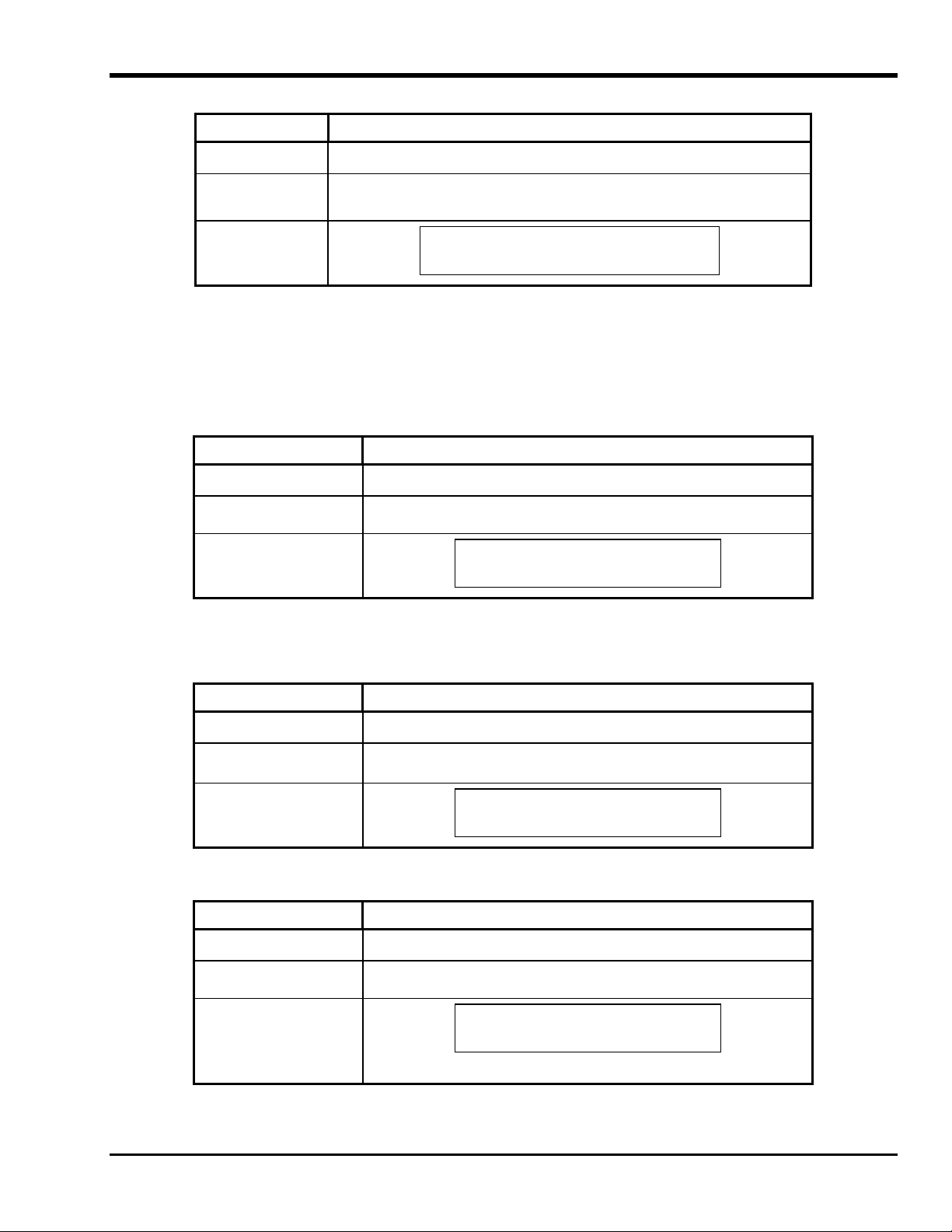
After clearing error (cycle power if drive error), the LCD displays the following message:
Indicator State, Character, or Message
Status LED
Single-character
display
LCD
Green, solid
Ultrium Tape Drive
Drive Empty
SCSI Wrap Test Function
This test performs a check of the SCSI circuitry from and to the SCSI connector.
To select the SCSI Wrap Test function, perform the following steps:
1. Verify that the drive is in Maintenance Mode shown when the Status LED is solid amber.
2. Press the Unload button once per second until the front panel indicators display the following:
Indicator State, Character, or Message
Status LED
Single-character display
LCD
Maint Mode: Select
SCSI Wrap(Inst Plug)
Amber, solid
Off
6
Before selecting this function, attach a SCSI wrap plug (not provided in accessory kit; contact ATAC) to the drive SCSI
connector (in place of the SCSI cable).
3. Press and hold the Unload button for two seconds to select SCSI Wrap Test. The
front panel indicators display the following:
Indicator State, Character, or Message
Status LED
Single-character display
LCD
SCSI Wrap
Amber, solid
6, flashing
drive automatically starts the test. The
Running!
If the test is successful, the test will loop and begin again.
4. Press the Unload button. The front panel indicators display the following:
Indicator State, Character, or Message
Status LED
Single-character display
LCD
Amber, solid
0
Ultrium Tape Drive
Drive Empty
Then the drive will exit Maintenance Mode.
36 Troubleshooting and Diagnostics
Page 49
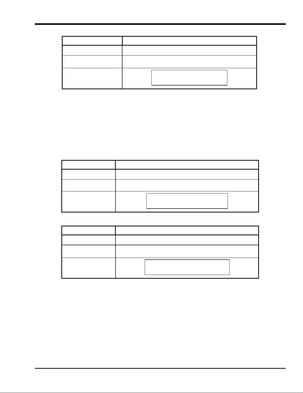
If the test fails, the front panel indicators display the following:
Indicator State, Character, or Message
Status LED
Single-character display
LCD
Error!
Amber, flashing
8, solid
Drive/SCSI Bus Error
Then the drive will exit Maintenance Mode.
To resolve the error, refer to Table 4-2 Error Codes, elsewhere in this chapter. To clear the error, cycle (remove, then
reapply) power to the LTO standalone.
Unmake FMR Tape
Use this function to direct the drive to erase the firmware data on a scratch data cartridge and rewrite the cartridge memory on tape. This
turns the cartridge into a valid scratch data cartridge.
To select the Unmake FMR Tape function, perform the following steps:
1. Verify that the drive is in Maintenance Mode shown when the Status LED is solid amber.
2. Press the Unload button once per second until the front panel indicators display the following:
Indicator State, Character, or Message
Status LED
Single-character display
Amber, solid
8
LCD
Maint Mode: Select
Unmake FMR Tape
3. Press and hold the Unload button for two seconds to select Unmake FMR Tape. The front panel indicators display the
following:
Indicator State, Character, or Message
Status LED
Single-character display
LCD
Unmake FMR Tape
Amber, solid
c, flashing
Load Drv FMR Tape
Troubleshooting and Diagnostics 37
Page 50
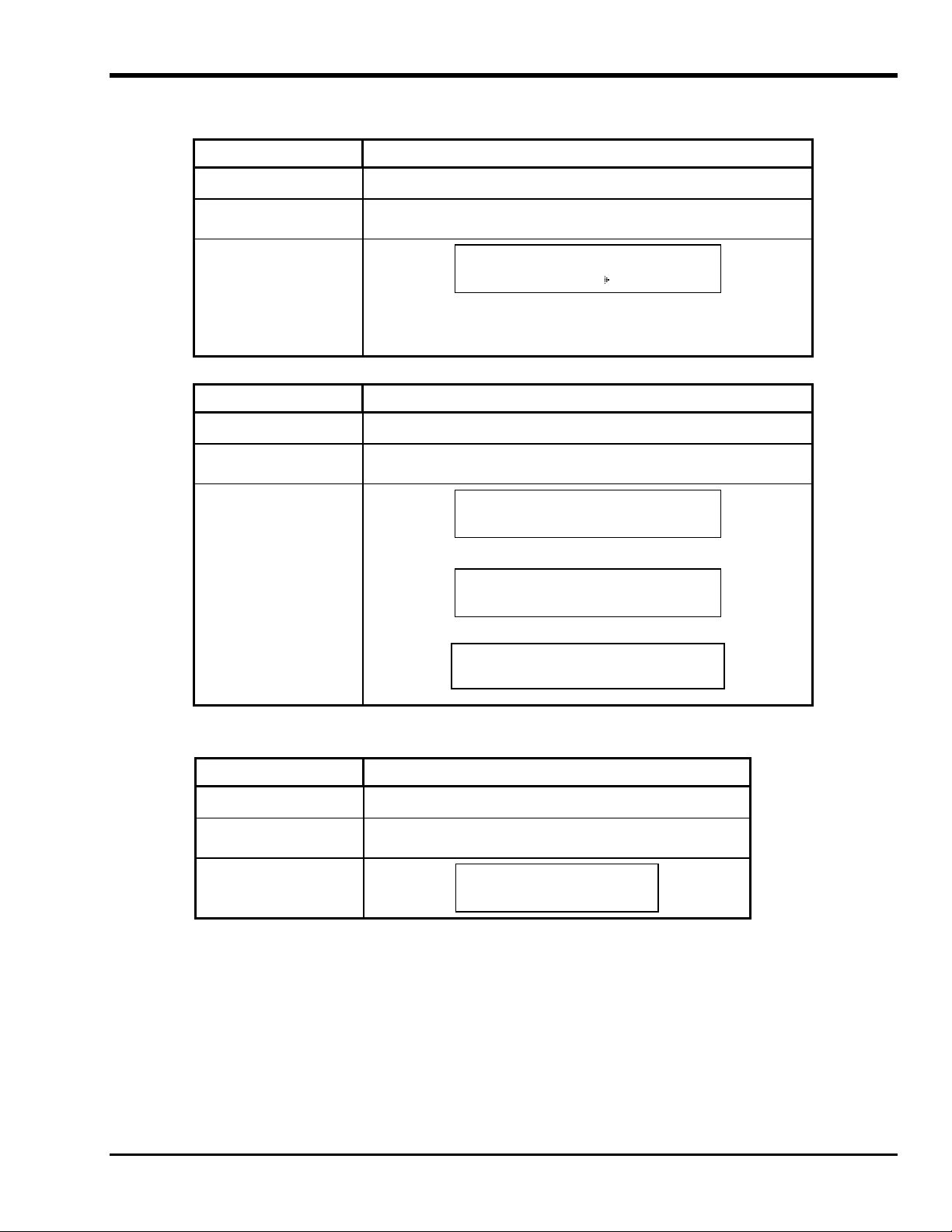
4. Within 60 seconds, insert the FMR cartridge (or the drive will exit Maintenance Mode).
After you insert the cartridge, the front panel indicators display the following:
Indicator State, Character, or Message
Status LED
Single-character display
LCD
Unmake FMR Tape
Amber, solid
8, flashing
Tape Loading ====
while the drive loads the FMR tape, then erases the firmware on the tape,
then rewrites the header in the cartridge memory to change the cartridge to a
valid scratch data cartridge.
If the operation is successful, the front panel indicators display the following:
Indicator State, Character, or Message
Status LED
Single-character display
LCD
Unmake FMR Tape
Amber, solid
0, solid
Completed!
followed by:
Cartridge Unloading
In Progress
followed by:
Ultrium Tape Drive
Drive Empty
The drive will then exit Maintenance Mode.
If the operation is not successful or the tape is already a valid scratch tape, the front panel indicators display the following:
Indicator State, Character, or Message
Status LED
Single-character display
LCD
ERROR!
Amber, solid
7, flashing
Media Error
To resolve the error, refer to Table 4-2 Error Codes, elsewhere in this chapter. To clear the error, cycle (remove, then
reapply) power to the LTO standalone.
38 Troubleshooting and Diagnostics
Page 51

Display Error Code Log
Use this function to display the last 10 error codes, one at a time (the codes are ordered; the most recent is presented first and the oldest–
tenth–is presented last.)
To select the Display Error Code Log function, perform the following steps:
1. Verify that the drive is in Maintenance Mode by observing that the Status LED is illuminated solid amber.
2. Press the Unload button once per second until the front panel indicators display the following:
Indicator State, Character, or Message
Status LED
Single-character display
LCD
3. Press and hold the Unload button for two seconds to select Display Error Code Log. The front panel indicators display
the following:
Indicator State, Character, or Message
Status LED
Single-character display
LCD
Maint Mode: Select
Display Err Code Log
Display Err Code Log
Amber, solid
9
Amber, solid
9, flashing
0. Media Error
4. After you select this function:
Press the Unload button to view the most recent error code.
Press the Unload button again to view the successive error codes.
If you press the Unload button after the tenth error code is shown, the drive will exit this function as well as the
Maintenance Mode function.
If there are no errors in the log, the front panel indicators display the following:
Indicator State, Character, or Message
Status LED
Single-character display
LCD
Maint Mode: Select
Amber, solid
0
Exit Maint Mode
5. To exit this function and Maintenance Mode, press and hold the Unload button for two seconds.
Troubleshooting and Diagnostics 39
Page 52
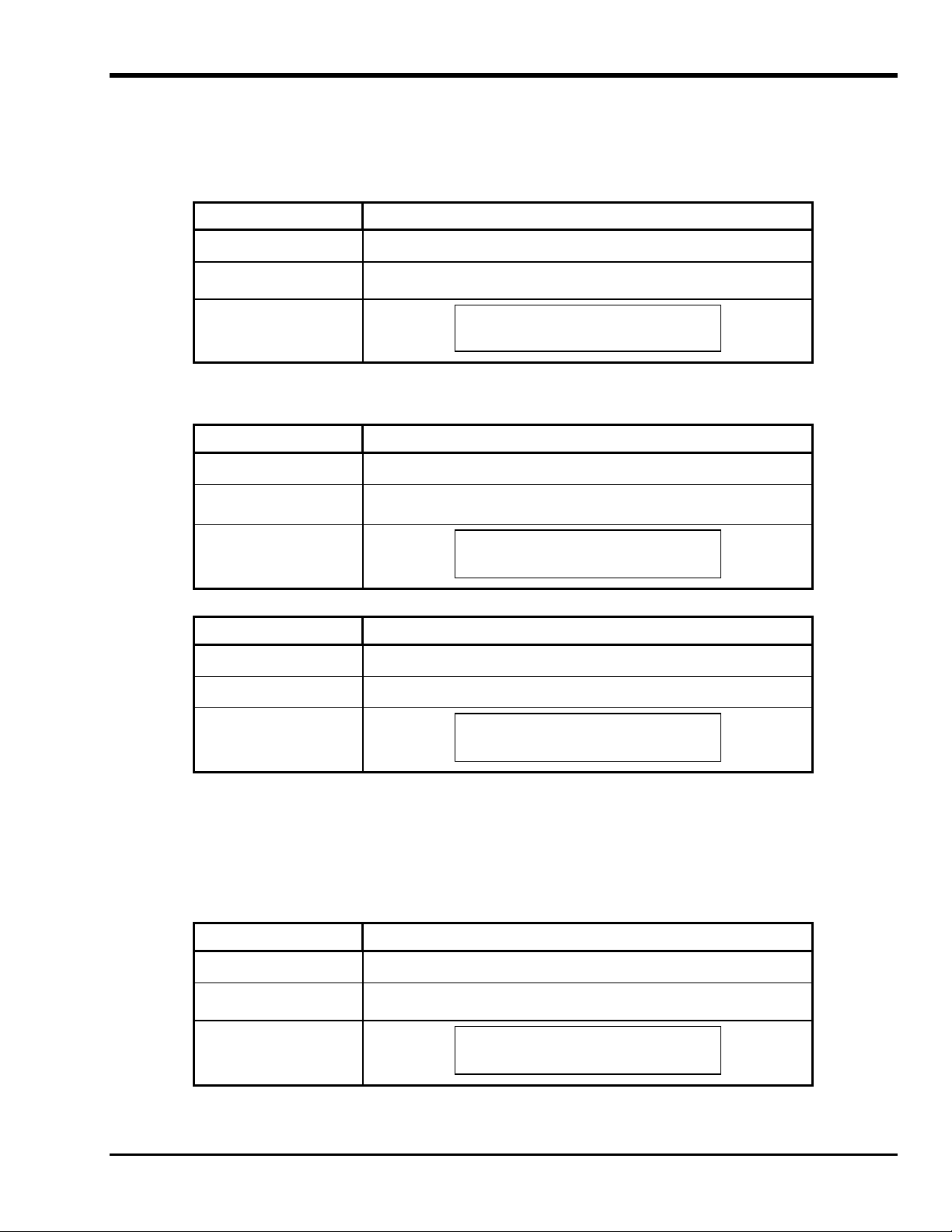
Clear Error Log
To select the Clear Error Log function, perform the following steps:
1. Verify that the drive is in Maintenance Mode shown when the Status LED is solid amber.
2. Press the Unload button once per second until the front panel indicators display the following:
Indicator State, Character, or Message
Status LED
Single-character display
LCD
3. Press and hold the Unload button for two seconds to select Clear Err Log.
The drive erases all errors from the error log, and the front panel indicators briefly display the following:
Indicator State, Character, or Message
Status LED
Single-character display
LCD
Maint Mode: Select
Clear Error Log
Clear Error Log
Amber, solid
a
Amber, solid
a, flashing
Completed!
Then your LTO standalone exits Maintenance Mode, and the front panel indicators display the following:
Indicator State, Character, or Message
Status LED
Single-character display Off
Green, solid
LCD
Ultrium Tape Drive
Drive Empty
Test Cartridge and Media
Use this function to perform tests to ensure that a suspect cartridge and its magnetic tape are acceptable.
To select the Test Cartridge & Media function, perform the following steps:
1. Verify that the drive is in Maintenance Mode shown when the Status LED is solid amber.
2. Press the Unload button once per second until the front panel indicators display the following:
Indicator State, Character, or Message
Status LED
Single-character display
LCD
40 Troubleshooting and Diagnostics
Maint Mode: Select
Test Media
Amber, solid
e
Page 53

3. Press and hold the Unload button for two seconds to select Test Cartridge & Media. The front panel indicators display
the following:
Indicator State, Character, or Message
Status LED
Single-character display
LCD
Test Media
Amber, solid
c, flashing
Load Scratch Tape
4. Within 60 seconds, insert the suspect cartridge (or the drive will exit Maintenance Mode).
After you insert the cartridge, the front panel indicators display the following:
Indicator State, Character, or Message
Status LED
Single-character display
LCD
Test Media
Amber, solid
e, flashing
Tape Loading ====
while the drive loads the suspect tape, followed by:
Test Media
Locating ====
followed by:
Test Media
Writing ====
followed by:
Test Media
Reading ====
Caution
Data on the suspect cartridge will be overwritten.
The drive will take approximately 15 minutes to run the tests.
If no error is detected, the test will loop and begin again.
5. Press the Unload button. The LTO standalone will rewind and unload the suspect tape. The front panel indicators display
the following, and the LTO standalone exits Maintenance Mode:
Indicator State, Character, or Message
Status LED
Single-character display
LCD
Test Media
Tape Unloading
Amber, flashing
0
Troubleshooting and Diagnostics 41
Page 54
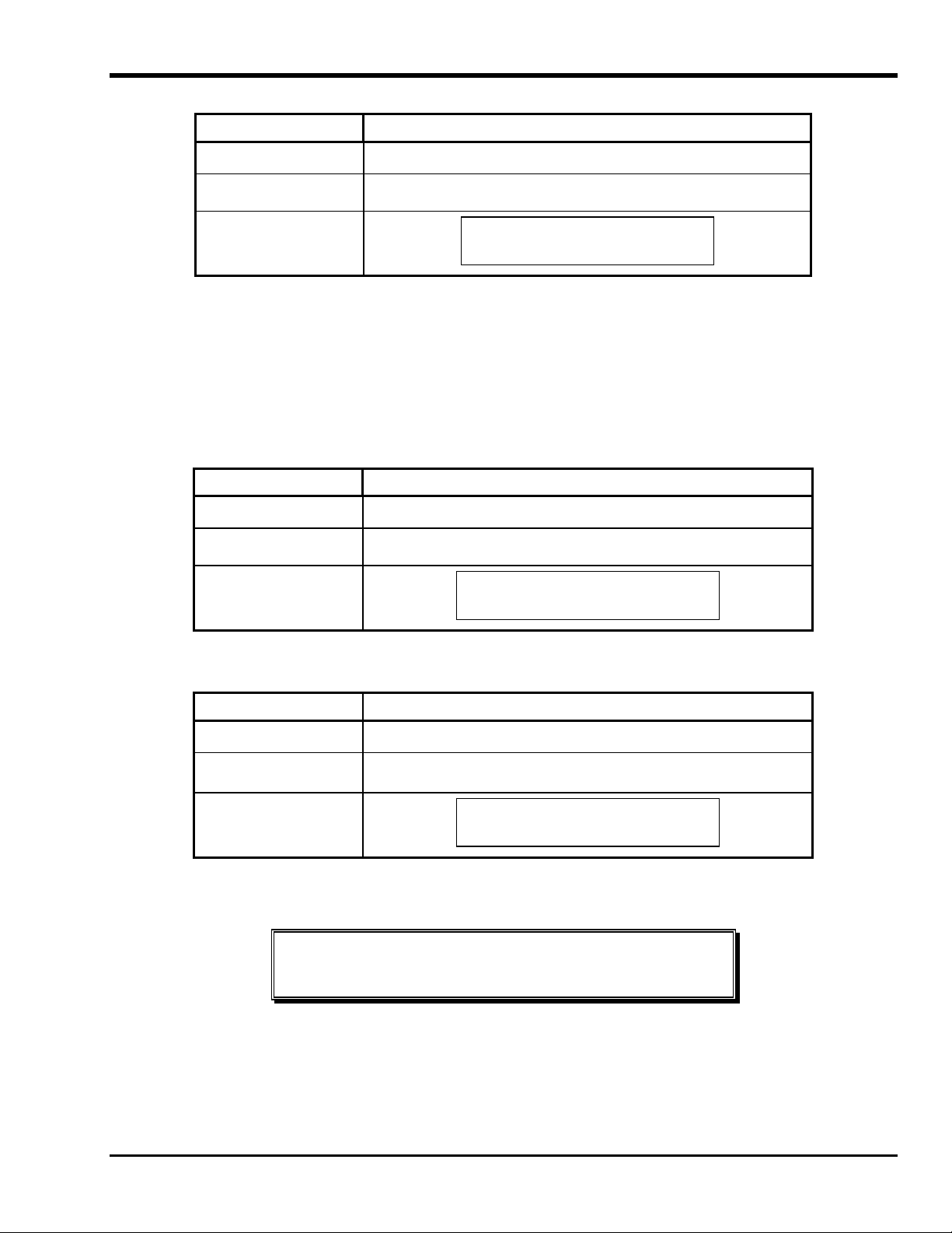
If an error is detected, the front panel indicators display the following:
Indicator State, Character, or Message
Status LED
Single-character display
LCD
Error!
Amber, flashing
7
Media Problem
and your LTO standalone will exit Maintenance Mode.
To resolve the error, refer to Table 4-2 Error Codes, elsewhere in this chapter.
Fast R/W Diagnostic
Use this function to determine whether the drive can properly load and unload cartridges, and read and write data.
To select the Fast R/W Diagnostic, perform the following steps:
1. Verify that the drive is in Maintenance Mode shown when the Status LED is solid amber.
2. Press the Unload button once per second until the front panel indicators display the following:
Indicator State, Character, or Message
Status LED
Single-character display
LCD
Maint Mode: Select
Fast R/W Diagnostic
Amber, solid
F
3. Press and hold the Unload button for two seconds to select Fast R/W Diagnostic.
After a short time the front panel indicators display the following:
Indicator State, Character or Message
Status LED
Single-character display
LCD
Fast R/W Diagnostic
Amber, solid
C, flashing
Load Scratch Tape
4. Within 60 seconds, insert a scratch data cartridge that is not write-protected into the drive (or the drive will exit
Maintenance Mode). Refer to Convert FMR Tape to Scratch Tape elsewhere in this chapter for the description of a
valid scratch data tape.
Caution
Insert only a scratch data cartridge for these tests. Data on the cartridge will be
overwritten.
42 Troubleshooting and Diagnostics
Page 55
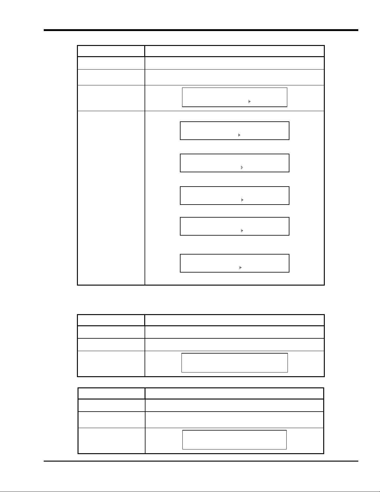
After you insert the cartridge, the front panel indicators display the following:
Indicator State, Character, or Message
Status LED
Single-character display
LCD
Fast R/W Diagnostic
Tape Loading ======
LCD which will be followed by:
Fast R/W Diagnostic
Writing ======
which will alternate with:
Fast R/W Diagnostic
Locating ======
for several minutes, followed by:
Fast R/W Diagnostic
Reading ======
which will alternate with:
Fast R/W Diagnostic
Locating ======
Amber, solid
F, flashing
which will loop back to Writing and continue for several minutes until the
display changes to:
Fast R/W Diagnostic
Erasing ======
And then it will repeat the previous steps until completed.
The drive takes approximately 20 minutes to complete the tests.
If the diagnostics are successfully completed, the test will loop and begin again.
5. Press the Unload button to exit Maintenance Mode. The front panel indicators display the following:
Indicator State, Character, or Message
Status LED
Single-character display Off
LCD
Ultrium Tape Drive
Off
Drive Empty
If an error occurs while the drive is running the Fast R/W Diagnostic, the front panel indicators display the following:
Indicator State, Character, or Message
Status LED
Single-character display
Amber, flashing
5, flashing
LCD
Error!
Drive Problem
Troubleshooting and Diagnostics 43
Page 56

The drive unloads, ejects the cartridge, exits Maintenance Mode, and the front panel indicators display the following:
Indicator State, Character, or Message
Status LED
Single-character display
LCD
Amber, flashing
5, flashing
Ultrium Tape Drive
Drive Empty
To resolve the error, refer to Table 4-2 Error Codes, elsewhere in this chapter.
To clear the error, cycle (remove, then reapply) power to the LTO standalone.
Test Head
Use these tests to ensure that the drive head and tape-carriage mechanics are working correctly.
To select the Test Head function, perform the following steps:
1. Verify that the drive is in Maintenance Mode shown when the Status LED is solid amber.
2. Press the Unload button once per second until the front panel indicators display the following:
Indicator State, Character, or Message
Status LED
Single-character display
LCD
Maint Mode : Select
Test Head
Amber, solid
h
3. Press and hold the Unload button for two seconds to select Test Head.
The front panel indicators display the following:
Indicator State, Character, or Message
Status LED
Single-character display
LCD
Test Head
Amber, solid
c, flashing
Load Scratch Tape
Within 60 seconds, insert a scratch data cartridge (or the drive will exit Maintenance Mode).
44 Troubleshooting and Diagnostics
Page 57
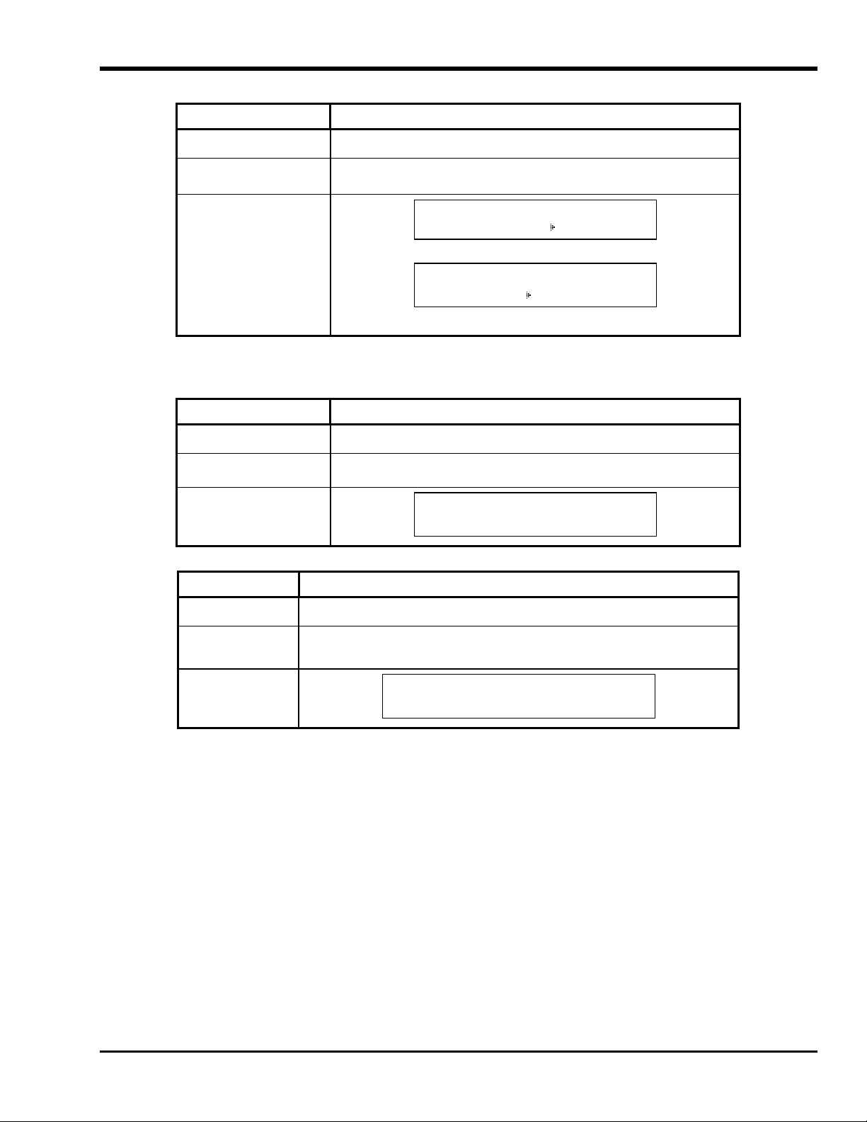
After you insert the scratch cartridge, the front panel indicators display the following:
Indicator State, Character, or Message
Status LED
Single-character display
LCD
Test Head
Amber, solid
h, flashing
Tape Loading ====
while the drive loads the scratch tape, followed by:
Test Head
Writing ====
The drive takes approximately 10 minutes to run the tests.
If no error is detected, the test will loop and begin again.
4. Press the Unload button. The LTO standalone rewinds and unloads the scratch tape. The front panel indicators display the
following, and the LTO standalone exits Maintenance Mode:
Indicator State, Character, or Message
Status LED
Single-character display
LCD
Test Head
Amber, flashing
0
Tape Unloading
If an error is detected, the front panel indicators display the following:
Indicator State, Character, or Message
Status LED
Single-character
display
LCD
Error!
Amber, flashing
5
Drive Problem
And your LTO standalone will exit Maintenance Mode.
To resolve the error, refer to the following Error Code table.
Troubleshooting and Diagnostics 45
Page 58

Error Codes and Messages
Table 4-2 describes LTO standalone error codes, LCD messages, possible causes and suggested actions to correct the error.
Table 4-2 Error Codes and Messages.
Code LCD Message Possible cause
Maint Mode: Select
0
Exit Maint Mode
Error!
1
Cooling Problem
Error!
2
Power Problem
No error. This code displays:
• When power is cycled
(turned off, then on) to the
drive.
• When diagnostics have
finished running and no error
occurred.
Note
The single-character display is
blank during normal operation
of the drive.
Maximum operating temperature
was exceeded.
Externally supplied power
exceeds the specified voltage
limits.
Corrective
No action required.
Remove any blockage that prevents air
from flowing freely through the drive.
Ensure that the operating temperature and
airflow is within the specified range (refer
to Appendix A Specifications, for the
operating temperature range).
If the operating temperature is within the
specified range and the problem persists,
contact ATAC.
Ensure that the power connector is
properly seated.
Ensure that the proper DC voltages are
being applied within the tolerances
allowed.
If the proper voltages are being applied
and the problem persists, contact ATAC.
action
3
Error!
A firmware error occurred. 1. Collect a drive dump from one of the
F/W Problem
46 Troubleshooting and Diagnostics
following:
• Server
• Ultrium Tape Drive (select
Function code
2. Power the drive off and on, then retry
the operation that produced the error.
3. If the problem persists, download
new firmware and retry the operation.
4. If the problem still persists, read a
drive dump, then call your next level
of support.
5 )
Page 59

Error!
4
Drive/FW Prob
Error!
5
Drive Problem
Error!
6
Drive/Media Prob
Firmware or drive problem. 1. Collect a drive dump from one of
A drive hardware failure
occurred. To prevent damage to
the drive or tape, the drive may
not allow you to insert a cartridge
until you turn the drive off, then
on.
The drive determined that an error
occurred, but it cannot isolate the
error to faulty hardware or the
data cartridge.
the following:
• Server
• Ultrium Tape Drive (select
Function code
Power the drive off then on, then retry the
operation that produced the error.
If the problem persists, download new
firmware and retry the operation; if new
firmware is not available, contact ATAC.
If the problem persists, contact ATAC.
If you know the cartridge volume serial
number (located on the cartridge label),
retry the operation with another cartridge:
• If the operation succeeded, the
original cartridge was defective.
Copy data from the defective
cartridge and discard it.
• If the operation failed with the same
error code, contact ATAC.
• If the operation failed with a different
error code, locate the code in this
table.
If you don’t know the cartridge volume
serial number, or if a problem occurs with
multiple cartridges:
• Run the drive diagnostics (function
1 ).
code
• If the drive diagnostics fail, contact
ATAC. If the drive diagnostics are
successful, run the Test Head
diagnostic (Function Code
• If the Test Head diagnostic fails,
contact ATAC.
• If the Test Head diagnostic is
successful, replace the cartridge that
caused the problem.
5)
H ).
Error!
7
Media Problem
8
Error!
An error occurred because of a
faulty tape cartridge.
A failure occurred in the drive
hardware or in the SCSI bus.
Replace the tape cartridge. If the problem
occurs with multiple tape cartridges,
contact ATAC.
Contact ATAC.
Drive/SCSI Problem
Error!
9
Drive/SCSI Problem
b, D, e,
F, or h
Troubleshooting and Diagnostics 47
A failure occurred in the drive
hardware or in the RS-422
connection.
No error or message assigned.
There may be a problem with the
single-character display.
Contact ATAC.
Turn the power off, then on and
determine whether all segments on the
single-character display are illuminated.
Page 60

a,
c
The performance of the drive is
degraded, but the drive is still
operational. .
The drive needs to be cleaned. Clean the drive. Refer to Cleaning the
To clear this error, cycle the drive power
or place the drive in maintenance mode.
If the problem persists, replace the drive.
Tape Head in Chapter 3.
Note
The code clears when you clean the
drive, or place the drive in Maintenance
Mode.
48 Troubleshooting and Diagnostics
Page 61

Appendix
Specifications
This Appendix . . .
❐ contains specification information on the LTO standalone.
49
Page 62

Drive
Type IBM® Ultrium™ Generation 1
Media Type LTO-1 LTO-2
Data Capacity 100 GB per cartridge (200 GB
Data Transfer Rate
(compressed mode)
Enclosure
Electrical Interface LVD/SE Ultra-2 SCSI or HVD
Physical Interface 68-pin, shielded, high-density device
Reliability
Maintenance
MTBF 250 000 power on hours at 100%
Physical
Dimensions 14.6 cm (5.75in.) height, 17.1 cm
Weight 6.59 kg (14.3 lb) 6.59 kg (14.3 lb)
Environment
Electrical 100–240 VAC, 50–60 Hz 100–240 VAC; 50–60 Hz
BTU/Hour 300 Under 250
Temperature
Humidity 10% to 80% Operating 10% to 80% Operating
Vibration 0.5G (5–500 Hz) Operating 0.2 G (2–200 Hz) Operating
Shock 15G Operating 30G Operating
LTO 200D LTO 400D
Contains an IBM® TotalStorage™ LTO
LTO™ tape drive
compressed, assuming 2:1
compression)
15 MB/sec (30 MB/sec, assuming 2:1
compression)
Ultra-2 SCSI
connector
Periodic cleaning of drive head using
LTO cleaning cartridge
duty cycle
(6.75in.) width, 33.6 cm (13.25in.)
depth
10 C to 38 C (50° to 100 F)
Operating
Ultrium 2 tape drive
200 GB per cartridge (400 GB
compressed, assuming 2:1 compression)
35 MB / sec (70 MB / sec, assuming 2:1
compression)
LVD Ultra-3 SCSI
68-pin, shielded, high-density device
connector
Periodic cleaning of drive head using
LTO cleaning cartridge
250 000 power on hours at 100% duty
cycle
14.6 cm (5.75in.) height, 17.1 cm
(6.75in.) width, 33.6 cm (13.25in.)
depth
10 C to 38 C (50° to100 F)
Operating
50 Troubleshooting and Diagnostics
Page 63

Index
51
Page 64

A
application software....................................................................7
C
cleaning
cartridge..........................................................................21, 50
drive......................................................................................21
drive head .............................................................................21
LTO Ultrium Cleaning Cartridge..........................................21
the enclosure .........................................................................21
Clear Error Log function...........................................................25
Copy Dump to Tape function ...................................................25
Create FMR Tape function .......................................................25
D
diagnostics
Drive R/W Diagnostic ..........................................................27
error codes ............................................................................46
Fast R/W Diagnostic.............................................................42
Force Drive Dump Function.................................................33
mode, exiting ........................................................................27
mode, starting .......................................................................26
SCSI Wrap Test Function.....................................................36
starting ..................................................................................26
Test Cartridge and Media......................................................40
Test Head..............................................................................44
dimensions................................................................................50
Display Error Code Log function..............................................25
drive
cleaning.................................................................................21
data transfer rate ...................................................................50
electrical interface.................................................................50
operating conditions..............................................................18
physical interface..................................................................50
status.....................................................................................16
type ...................................................................................2, 50
Drive R/W Diagnostic function ................................................25
E
electrical ...................................................................................50
environmental attributes ...........................................................50
Error Code listing .....................................................................46
Exit Maintenance Mode function..............................................25
F
Fast R/W Diagnostic function...................................................25
firmware
FMR tape ..............................................................................37
updating ................................................................................29
Force Drive Dump function......................................................25
front panel
about .......................................................................................3
SCSI .......................................................................................7
host software
about....................................................................................... 7
installing............................................................................... 13
humidity ...................................................................................50
I
Insert Cartridge function ..........................................................25
installing
host software ........................................................................13
LTO Standalone .....................................................................9
multiple units........................................................................ 10
unpacking ............................................................................. 10
interface cable
connecting ............................................................................10
L
LCD
about....................................................................................... 4
messages............................................................................... 18
LED
indicators.............................................................................. 17
loading
tape cartridges ......................................................................18
M
maintenance
Clear Error Log ....................................................................40
Copy the Drive Dump to Tape .............................................34
Display Error Code Log ....................................................... 39
firmware, updating ...............................................................29
FMR tape, creating............................................................... 31
routine ..................................................................................21
Unmake FMR Tape.............................................................. 37
Update Drive Firmware from FMR Tape............................. 29
Maintenance Mode................................................................... 25
exit........................................................................................ 27
starting.................................................................................. 26
Mean Time Between Failures................................................... 50
P
packing ..................................................................................... 10
packing materials......................................................................10
physical attributes..................................................................... 50
POST
about..................................................................................... 16
status..................................................................................... 16
troubleshooing...................................................................... 24
power
connector................................................................................ 5
switch .........................................................................5, 24, 25
turning on .............................................................................13
Power-on Self-Test.......................................................See POST
precautions .................................................................................v
H
host adapter
installing ...............................................................................10
R
rear panel
about....................................................................................... 5
52
Page 65

reliability...................................................................................50
S
safety notices ..............................................................................v
SCSI
adapter ..................................................................................24
bus.........................................................................................24
bus termination .....................................................................13
cable......................................................................................24
compatibility...........................................................................7
connectors...............................................................................5
host adapter.............................................................................7
ID....................................................................................12, 24
ID Switch................................................................................5
interface ..................................................................................2
interface cable.......................................................................10
terminator..............................................................................24
SCSI Wrap Test function..........................................................26
shock.........................................................................................50
single character display
about .......................................................................................4
single red dot
about .......................................................................................4
specifications ............................................................................49
status
LED indications....................................................................17
messages .........................................................................16, 46
status LED
about .......................................................................................4
surrounding environment..........................................................10
system configuration.................................................................24
T
tape cartridges
allowed ...................................................................................5
handling.................................................................................. 7
humidity .................................................................................5
removing ..............................................................................20
storage ....................................................................................6
temperature............................................................................. 5
write-protect ........................................................................... 6
temperature............................................................................... 50
Test Head diagnostic function.................................................. 47
Test Head function ................................................................... 25
Test Media function..................................................................25
troubleshooting
chart...................................................................................... 24
diagnostics............................................................................ 25
maintenance mode................................................................ 25
U
unload button
about....................................................................................... 4
Unmake FMR Tape function.................................................... 26
Update Drive Firmware function..............................................25
Use Cleaning Tape LED...........................................................21
V
vibration ...................................................................................50
W
warnings ..................................................................................... v
weight....................................................................................... 50
write-enabled............................................................................ 18
write-protect
about..................................................................................... 20
tape catridges.......................................................................... 6
Index 53
 Loading...