

Page 1

Quantum|ATL PowerStor L200
Series Library
User’s Guide
6322500-04
Ver. 4, Rel. 0
Page 2

Quantum|ATL PowerStor L200 Series Library User’s Guide, 6322500-04, Ver. 4, Rel. 0, August 20 01, Ma de in
USA.
ATL Products, Inc. provid es th is publication “as is” without warranty of an y kin d, eit her expr ess or im pli ed,
including but not limited to the implied warranties of merchantability or fitness for a particular purpose.
ATL Products, Inc. may revise this publication from time to time without notice. Quantum|ATL is the
generally known alternative designation of ATL Products, Inc.
COPYRIGHT STATEMENT
Copyright 2001 by ATL Products, Inc. All rights reserved.
Your right to copy this manual is limited by copyright law. Making copies or adaptations without prior
written authorizati on of ATL Produ cts, Inc. is proh ibited by law an d constitu tes a punis hable v iolati on of the
law.
TRADEMARK STATEMENT
Prism Library Architect ure, I nt elliG r ip, S tac kLin k, Web A dmin, and We bLi br arian are all trademarks of ATL
Products, Inc.
Other trademarks may be mentioned herein which belong to other companies.
6207947-06cP 56
Page 3

Contents
Preface xiii
Chapter 1 Overview 1
Library Configuration............................................................................1
Features....................................................................................................2
Library Components..............................................................................3
Operator Control Panel (OCP).......................................................3
Library Door.....................................................................................5
Back Panel.........................................................................................5
Optional Bar Code Reader..............................................................6
Cartridge Handling Mechanism....................................................7
Tape Drive......................................................................... ......... .......8
6-Cartridge Magazine......................................................................9
Element Numbering Convention................................................10
Quantum|ATL PowerStor L200 Series Library User’s Guide iii
Page 4

Contents
Chapter 2 Installing the Library 11
Selecting an Installation Location ......................................................12
Space Requirements.......................................................................12
Surface Strength and Inclination .................................................12
Power and Grounding...................................................................12
Power Cord.....................................................................................12
Environmental Specifications.......................................................1 3
Receiving the Library........................................................ ...................14
Unpacking the Library ..................................................................14
Rack Mount Kit Installation .........................................................15
Connecting the Library........................................................................16
Running the Power-on Self-test..........................................................18
Configuring the Library.......................................................................19
Verifying the SCSI Settings...........................................................19
Chapter 3 Operator Control Panel 21
OCP Functions ......................................................................................22
OCP Menus.....................................................................................22
Status ......................................................................................................25
Eject/Unlock .........................................................................................28
SCSI ID...................................................................................................29
Viewing the SCSI ID Settings.......................................................30
Changing the SCSI ID Settings.....................................................30
Mode.......................................................................................................31
Viewing a Mode .............................................................................33
Setting a Mode................................................................................33
Optional Autoclean Mode ............................................................34
Firmware Updates .................................... ......... ......... ...................35
Information............................................................................................35
Code Update..........................................................................................36
Installing New Drive Microcode .................................................36
Tests........................................................................................................37
iv Quantum|ATL PowerStor L200 Series Library User’s Guide
Page 5

Contents
Chapter 4 Using the Library 39
Using the Library Door........................................................................39
Opening the Library Door............................................................41
Closing the Library Door..............................................................41
Using Tape Cartridges.........................................................................42
Inserting a Cartridge .....................................................................42
Removing a Cartridge...................................................................44
Loading a Cartridge.......................................................................45
Unloading a Cartridge ........................................... ......... ......... .....46
Using the Cleaning Cartridge ......................................................46
Handling and Storing Cleaning Cartridges...............................47
Cln Message....................................................................................48
Inserting Bar Code Labels.............................................................48
Using the Cartridge Magazine ...........................................................49
Inserting the Magazine..................................................................49
Removing the Magazine...............................................................50
Chapter 5 SCSI Interface 51
General SCSI Bus Operation...............................................................51
Data Transfer..................................................................................52
Initiator/Target Operation...........................................................52
SCSI IDs and LUNs........................................................................52
Unit Attention Condition..............................................................53
Behavior Around Power-On and SCSI Bus Reset.....................53
Other SCSI Functionality..............................................................54
Bus Phases.......................................................................................54
Attention Signal Response............................................................54
SCSI Message System...........................................................................54
Status Phase....................................................................................54
Bus Free...........................................................................................56
Bus Parity Errors............................................................................56
Chapter 6 Troubleshooting Guidelines 57
Basic Library Operation.......................................................................58
Quantum|ATL PowerStor L200 Series Library User’s Guide v
Page 6

Contents
Operation Failure..................................................................................59
Write-Operation Failure................................................................59
Error Conditions.............................................................................59
Power Problems .............................................................................59
Appendix A Specifications 61
Physical Specifications.........................................................................62
Performance Specifications.................................................................63
Power Specifications ............................................................................63
Environmental Specifications.............................................................64
Operating Vibration Specifications....................................................65
Operating Shock Specifications..........................................................66
Non-Operating Vibration Specifications...........................................66
Non-Operating Shock Specifications.................................................67
Electromagnetic Interference (EMI) Susceptibility..........................68
EMI Emissions................................................................................68
Conducted Emissions....................................................................69
Radiated Emissions........................................................................69
Radiated Susceptibility..................................................................69
Conducted Susceptibility..............................................................70
ESD Failure Level Limits ..............................................................70
Acoustic Noise Emissions ...................................................................71
Drive Reliability Factors......................................................................72
Appendix B Error Messages and Definitions 73
Error Messages...............................................................................73
Error Definitions ............................................................................76
Appendix C Regulatory Statements 81
FCC Statement ................................................. ......... ......... ...................81
Industry Canada (Digital Apparatus) ...............................................82
Notice for USA and Canada Only......................................................83
Laser Statement.....................................................................................84
Battery Statement..................................................................................85
vi Quantum|ATL PowerStor L200 Series Library User’s Guide
Page 7

Contents
Glossary 87
Index 93
Quantum|ATL PowerStor L200 Series Library User’s Guide vii
Page 8

Contents
viii Quantum|ATL PowerStor L200 Series Library User’s Guide
Page 9

Figures
Figure 1 OCP.......................................................................................4
Figure 2 Library Door........................................................................5
Figure 3 Back Panel............................................................................6
Figure 4 Bar Code Reader .................................................................7
Figure 5 Cartridge Handling Mechanism.......................................8
Figure 6 Library Magazine (Loaded)............................................... 9
Figure 7 Storage Array ....................................................................1 0
Figure 8 Unpacking the Library.....................................................15
Figure 9 Rear Panel Cable Connectors..........................................16
Figure 10 SCSI Cabling stand-alone Connection Scenario ...........17
Figure 11 Slot Locations ....................................................................40
Figure 12 Cartridge Write-Protect Switch ......................................43
Figure 13 Cartridge Retaining Tab ..................................................44
Figure 14 Bar Code Label Insertion.................................................49
Figure 15 Cartridge Magazine..........................................................50
Figure 16 Opening the Cartridge Door...........................................58
Figure 17 Library Dimensions..........................................................62
Quantum|ATL PowerStor L200 Series Library User’s Guide ix
Page 10

Figures
x Quantum|ATL PowerStor L200 Series Library User’s Guide
Page 11

Tables
Table 1 POST Pass/Error Messages.............................................18
Table 2 SCSI ID Default Settings..................................................19
Table 3 OCP LCD Menu Structure...............................................22
Table 4 Status Options...................................................................26
Table 5 Eject/Unlock Options ......................................................28
Table 6 SCSI ID Options................................................................29
Table 7 Mode Options....................................................................31
Table 8 Information Messages......................................................35
Table 9 Code Update Messages....................................................36
Table 10 Tests Options.....................................................................37
Table 11 Cln Message Indications..................................................48
Table 12 Status Bytes........................................................................55
Table 13 Library Dimensions..........................................................62
Table 14 Power Specifications.........................................................63
Table 15 Environmental Specifications .........................................6 4
Table 16 Operating Vibration Specifications................................65
Table 17 Operating Shock Specifications......................................66
Quantum|ATL PowerStor L200 Series Library User’s Guide xi
Page 12

Tables
Table 18 Non-Operating Vibration Specifications.......................66
Table 19 Random Vibration Specifications...................................67
Table 20 Non-Operating Shock Specifications.............................67
Table 21 Conducted Emission Limits............................................6 9
Table 22 Radiated Emissions (30 MHz to 1000 MHz).................69
Table 23 ESD Failure Level Limits.................................................70
Table 24 Acoustic Noise Emissions (English)...............................71
Table 25 Acoustic Noise Emissions (German)..............................71
Table 26 OCP Error Messages .........................................................73
Table 27 Library Error Definitions.................................................76
xii Quantum|ATL PowerStor L200 Series Library User’s Guide
Page 13

3UHIDFH
This manual introduces the PowerStor L200 Series library (library)
and describes library operations, configuration, servicing, and
basic troubleshooting.
$XGLHQFH
3XUSRVH
This manual is written for library operators.
This manual provides the following information about the library:
• Installing the library
• Basic library operations
• Operator control panel
• Using the library
• Service commands
• SCSI interface
• Troubleshooting
Quantum|ATL PowerStor L200 Series Library User’s Guide [LLL
Page 14

Preface
1RWDWLRQDO
&RQYHQWLRQV
This manual uses the following conventions:
Caution: Cautions indicate potential hazard to equipment or
data.
Warning: Warnings indicate potential hazard to personal
safety.
Note: Note emphasizes important information related to the
main topic.
This manual uses the following conventions:
• Right side of the library — Refers to the right side as you face
the component being described.
• Left side of the library — Refers to the left side as you face the
component being described.
• b — All binary numbers are succeeded by “b.”
• h — All hexadecimal numbers are succeeded by “h.”
• Error or attention conditions are represented in parenthesis
that translate as follows:
(SK=S ASC=AA ASCQ=QQ)
where:
S — hexadecimal sense key value
AA — hexadecimal additional sense code
QQ — hexadecimal additional sense code qualifiers
[LY Quantum|ATL PowerStor L200 Series Library User’s Guide
Page 15

Preface
5HODWHG
'RFXPHQWV
The following documents are related to the library:
'RFXPHQW
1R 'RFXPHQW7LWOH
6321102 Quantum|ATL
PowerStor L200 Series
Library Unpacking
Instructions
6&6,6SHFLILFDWLRQ
'RFXPHQW
'HVFULSWLRQ
Contains information
necessary to receive and
unpack the library
The SCSI-2 communications specification is the proposed
American National Standard for information systems, dated
March 9, 1990. Copies may be obtained from:
Global Engineering Documents
15 Inverness Way, East
Englewood, CO 80112
(800) 854-7179 or (303) 397-2740
&RQWDFWV 4XDQWXP_$7/&RUSRUDWH+HDGTXDUWHUV
To order documentation on the library or other products contact:
Quantum|ATL
P.O. Box 57100
Irvine, CA 92619-7100
(949) 856-7800
(800) 284-5101
Quantum|ATL PowerStor L200 Series Library User’s Guide [Y
Page 16

Preface
7HFKQLFDO3XEOLFDWLRQV
To comment on existing documentation send e-mail to:
atl-docs@atlp.com
:RUOG:LGH:HE
Visit the Quantum|ATL home page at:
http://www.atlp.com
&XVWRPHU6XSSRUW
The Quantum|ATL Customer Support Department provides a
24-hour help desk that can be reached at:
Direct: (949) 725-2100
United States: (800) 284-5101
Asia/Pacific Rim: (Internat ional Code)
+61 7 3862 4834
Europe/Middle East/Africa: (International Code)
+44 (0) 1256 848748
Send faxes for the Customer Support Department to:
North/South America: (949) 725-2176
Asia/Pacific Rim: (Internat ional Code)
+61 7 3862 4677
Europe/Middle East/Africa: (International Code)
+44 (0) 1256 848777
Send e-mail for the Customer Support Department to:
North/South America:
helpdesk@atlp.com
Asia/Pacific Rim: ATL-helpdesk-apac@atlp.com
Europe/Middle East/Africa: eurohelp@atlp.com
[YL Quantum|ATL PowerStor L200 Series Library User’s Guide
Page 17

Chapter 1
1Overview
This chapter provides an overall desc ription of the PowerStor L2 00
Series library (library) and includes the following sections:
• Library Configuration
• Features
• Library Components
Library Configuration 1
The library can hold up to eight c artridges and houses a single tape
drive. The library is available in rack mount or desktop
configurations and is available with either single-ended or
differential SCSI interfaces.
Quantum|ATL PowerStor L200 Series Library User’s Guide 1
Page 18

Chapter 1 Overview
Features
Features 1
The library provides the following features:
• Automatic tape operations
• Library status display via the operator control panel (OCP):
• Tape drive status and activity
• Tape drive error status
• Magazine slot status
• Loaded tape cartridge conditions
• Mode control:
• Automatic random access to all tape cartridges
• Sequential access to tape cartridges in a single cycle
• Sequential access to tape cartridges in circular cycles
• Optional bar code reader reads the tape cartridge label bar
codes
• Optional auto clean mode automatically cleans drives
when required
• User selection of cartridges to be loaded into the tape drive
• SCSI ID selection via the OCP
• Tape drive microcode updates via the SCSI bus or cartridge
• Library code or firmware updates via SCSI bus
• Display device microcode and hardware revision numbers
• User directed tests for the library
• Embedded diagnostic software displays status for head
cleaning, library operation, and tape drive operations
2 Quantum|ATL PowerStor L200 Series Library User’s Guide
Page 19

Chapter 1 Overview
Library Components
Library Components 1
The library consists of these major components:
• OCP
• Library door
• Back panel
• Bar code reader (optional)
• Cartridge handling mechanism (CHM) (also referred to as the
loader, elevator, or medium changer)
• Tape drive
• 6-cartridge removable magazine
• 2-cartridge fixed internal magazine
Operator Control Panel (OCP)
Caution: Do not attempt to remove components or perform
maintenance procedures on the library. Maintenance
procedures are performed by field service
technicians.
The OCP is located on the front panel of the library (see figure 1
1
and controls all library local functions. The OCP consists of:
• A liquid crystal display (LCD)
• A power indicator light-emitting diode (LED)
• Four buttons: Previous, Next, Select, and Enter
The LCD displays up to two lines of characters that contain a
mixture of messages and field codes (see figure 1
).
)
Quantum|ATL PowerStor L200 Series Library User’s Guide 3
Page 20

Chapter 1 Overview
Library Component s
Figure 1 OCP
Previous1
Next1Enter 1LCD1
Select1
Power
LED
1
Using the OCP, you can:
• View tape drive status and activity
• View error messages
• View magazine slot status
• View the drive and loader controller configuration
• Set the SCSI ID for the drive and loader controller
• Lock or unlock the magazine door
• Exercise and test the CHM
See chapter 3, Operato r C o n t r o l Panel
for more information on the
OCP.
4 Quantum|ATL PowerStor L200 Series Library User’s Guide
Page 21

Chapter 1 Overview
Library Components
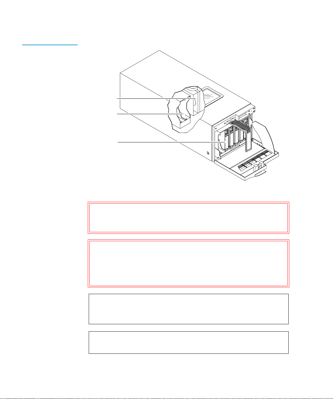
Library Door 1
Figure 2 Library Door
The library door provides access to a 6-cartridge removable
magazine, and a 2-cartridge internal fixed magazine. See Opening
the Library Door on page 41 for more information on opening the
library door.
6-cartridge
magazine
Magazine handle
Library door
Back Panel 1
The back panel of the library (see fi gur e 3
) contains:
• Power switch and connector
• SCSI connectors
• Power supply
• Serial port (only for use by a service representative)
Quantum|ATL PowerStor L200 Series Library User’s Guide 5
Page 22

Chapter 1 Overview
Library Component s
Figure 3 Back Panel
Power switch
Power connector
SCSI connector
Serial port
Optional Bar Code Reader
The optional bar code reader performs cartridge inventories in less
1
than three minutes. When installed, it occupies a narrow space
inside the library, to the left of the tape cartridge magazine (see
figure 4
).
The bar code reader assembly contains a scan head that
communicates with the library controller card over an RS-422
communications link. During a cartridge inventory, the scan head
illuminates and reads the bar code labels on the cartridges and
transmits the results to the library controller card.
6 Quantum|ATL PowerStor L200 Series Library User’s Guide
Page 23

Figure 4 Bar Code
Reader
Chapter 1 Overview
Library Components
Scan head
Bar code reader
assembly
Cartridge Handling Mechanism
The cartridge handling mechanism (CHM) is a compact,
1
bidirectional roller system that enables simple horizontal
movement between the magazine and the tape drive (see figure 5
This design allows you to add and remove cartridges from the
front of the magazine.
Note: If the CHM, or elevator, is positioned so that it blocks the
rear of the slot where the cartridge is to be loaded or
unloaded, it is not possible to perform a load or unload
operation. The cartridge cannot be pushed far enough
into the slot so that it locks or unlocks into or out of its
position in the magazine. In this instance, the magazine
will have to be removed in order to load or unload that
particular magazine slot.
Quantum|ATL PowerStor L200 Series Library User’s Guide 7
).
Page 24

Chapter 1 Overview
Library Component s
Figure 5 Cartridge
Handling Mechanism
The CHM contains sensors that monitor cartridge location, gripper
location and timing information. These sensors al low the library to
operate as a random access system that provides direct, quick
access to any of the cartridges in the storage array.
Tape drive
CHM
Tape Drive 1
The tape drive is mounted to a sturdy metal bracket assembly
which includes a built-in fan unit and SCSI data connectors. It
affords easy access in the event that the drive requires
replacement.
8 Quantum|ATL PowerStor L200 Series Library User’s Guide
Page 25

Chapter 1 Overview
Library Components
6-Cartridge Magazine
Figure 6 Library
Magazine (Loaded)
The includes one 6-cartridge tape magazine (see figure 6
1
accessed from the door on the front of the unit. The magazine
stores up to six data cartridges. The magazine can also be rem oved
and used for off-site storage.
Tape
cartridge
) that is
Pivoting
carrying
handle
The magazine is keyed to prevent improper cartridge insertion and
locks each cartridge in place once inserted. A push on a cartridge
releases it for removal without the need to remove the entire
magazine.
Note: If the CHM, or elevator, is positioned so that it blocks the
rear of a slot where a cartridge is to be loaded or
unloaded, it is not possible to pe rform the load or unloa d
operation. The cartridge cannot be pushed far enough
into the slot so that it locks or unlocks into or out of its
position in the magazine. In this instance, the magazine
will have to be removed in order to load or unload that
particular magazine slot.
Quantum|ATL PowerStor L200 Series Library User’s Guide 9
Page 26

Chapter 1 Overview
Library Component s
Element Numbering Convention
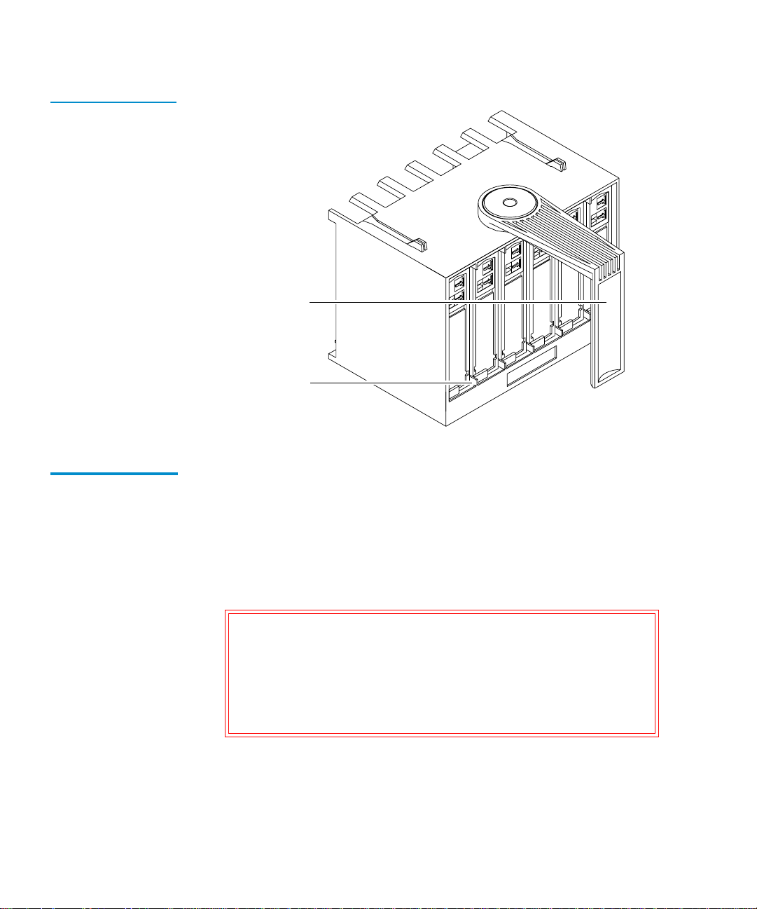
Figure 7 Storage
Array
The storage array (see figure 7
• One 6-cartridge magazine
1
• Two internal storage slots
• One tape drive
) includes:
Tape drive
01 2 3 4 5
6-cartridge
magazine
67
2 internal slots
10 Quantum|ATL PowerStor L200 Series Library User’s Guide
Page 27

Chapter 2
2Installing the Library
This chapter contains information needed to install, configure and
operate the library. The installation procedure is divided into the
following general tasks:
• Selecting an Installation Location
• Receiving the Library
• Rack Mount Kit Installation
• Running the Power-on S elf-test
• Configuring the Library
• Selecting an Installation Location
Quantum|ATL PowerStor L200 Series Library User’s Guide 11
Page 28

Chapter 2 Installing the Library
Selecting an Installation Location
Selecting an Installation Location 2
When selecting an installation location for the library, consider:
• Space requirements
• Installation surface strength and inclination
• Power and grounding
• Environmental specifications
Space Requirements
Surface Strength and Inclination
Power and Grounding
Power Cord 2
The library requires 6 inches space behind it for cables and
2
connections. The library also requires 6 inches in front of it for
opening and closing the library door. No extra space is required to
either side of the library. To remove and replace the library
enclosure, you need an overhead clearance slightly greater than
the height of the library (see Physical Specifications
on page 62).
Place the library on a clean , lev el surface. If the library is placed on
2
a desk or table, make sure it is sturdy enough to support the
library’s weight, 37 pounds (17 kilograms) (empty).
The electrical ratings for the library are 100 to 1 20/200 to 240 VAC,
2
50/60 Hertz.
A 110/120 VAC power cord is supplied with your library. If your
locale does not use 110/120 VAC, the power cord used with this
equipment must meet this criteria:
• A minimum of 18/3 AWG, 60
°C, Type SJT
• UL and CSA certified cordage rated for use at 250 VAC with a
current rating that is at least 125% of the current rating of the
product (in Europe, the cordage must have the HAR mark)
12 Quantum|ATL PowerStor L200 Series Library User’s Guide
Page 29

Chapter 2 Installing the Library
Selecting an Installation Location
• The AC plug must be terminated in a grounding-type male
plug designed for use in your country and it must also have
marks showing certification by an agency acceptable in the
country
• The connector at the product end must be an IEC 320 type C13
female connector
• The cord must be no longer than 14.5 feet (4.5 meters)
Warning: Do not attempt to modify or use an external 110/120
VAC power cord for 220/240 VAC input power.
Modifying the power cord can cause personal injury
and severe equipment damage.
Environmental Specifications
The installation location should meet the following environmental
2
specifications for operating the Powerstor library:
• Temperature: 50
°F to 104°F (10°C to 40°C)
• Relative humidity: 20% to 80% noncondensing
• Humidity gradient: 10% per hour
• Dry bulb temperature: 50
• Wet bulb temperature: 77
• Temperature gradient: 19.8
• Temperature shock: 18
°F to 104°F (10°C to 40°C)
°F (25°C)
°F (11°C) per hour across the range
°F (10°C) over two minutes
• Altitude: -500 feet to 10,000 feet (-150 meters to 3000 meters)
• Air:
Free of airborne contaminates (for example dust, paper
particles, fibers, and so on)
Quantum|ATL PowerStor L200 Series Library User’s Guide 13
Page 30

Chapter 2 Installing the Library
Receiving the Library
Receiving the Library 2
When receiving the library from the shipper, unpack the library as
close to the installation location as possible.
Inspect the shipping pallet and carton for damage that may have
occurred during shipment and immediately report any damage to
the shipper.
Warning: The library weighs 37 lbs (17 kg). Two people should
perform any procedure that involves lifting or
moving the library.
Caution: If you are installing the rack mount version of the
library, use the PowerStor Rack Mount Installation Kit.
This kit provides necessary support brackets.
Unpacking the Library
The unpacking instructions vary depending upon whether it is a
desktop or rack mount library. If i t is a desktop l ibrary, you s hould
have only one shipping carton. If it is a rack mount library, you
will have two shipping cartons. The larger carton contains the
library, and the smaller carton contains the rack mount kit.
To unpack the library (see figure8
2
1 Remove the accessory kit.
2 Remove the packing foam from the top of the library.
3 Remove the library from the shipping carton.
4 Remove the library from the shipping bag.
5 Place the library in the installa tion location. If it is a rack mount
):
library, refer to the instructions supplied with the PowerStor
Rack Mount Kit.
6 Save the box and its packing materials in case the library
requires shipment at a later date.
14 Quantum|ATL PowerStor L200 Series Library User’s Guide
Page 31

Figure 8 Unpacking
the Library
Chapter 2 Installing the Library
Receiving the Library
Accessory kit
Packing foam
Library
Rack Mount Kit Installation
Packing foam
Shipping carton
Before installing the rack mount kit in the rack, compare the
2
contents of the carton with the packing list inside the shipping
carton. To install the rack mount kit in the rack, refer to the
instructions provided in the smaller shipping carton.
Quantum|ATL PowerStor L200 Series Library User’s Guide 15
Page 32
Chapter 2 Installing the Library
Connecting the Library
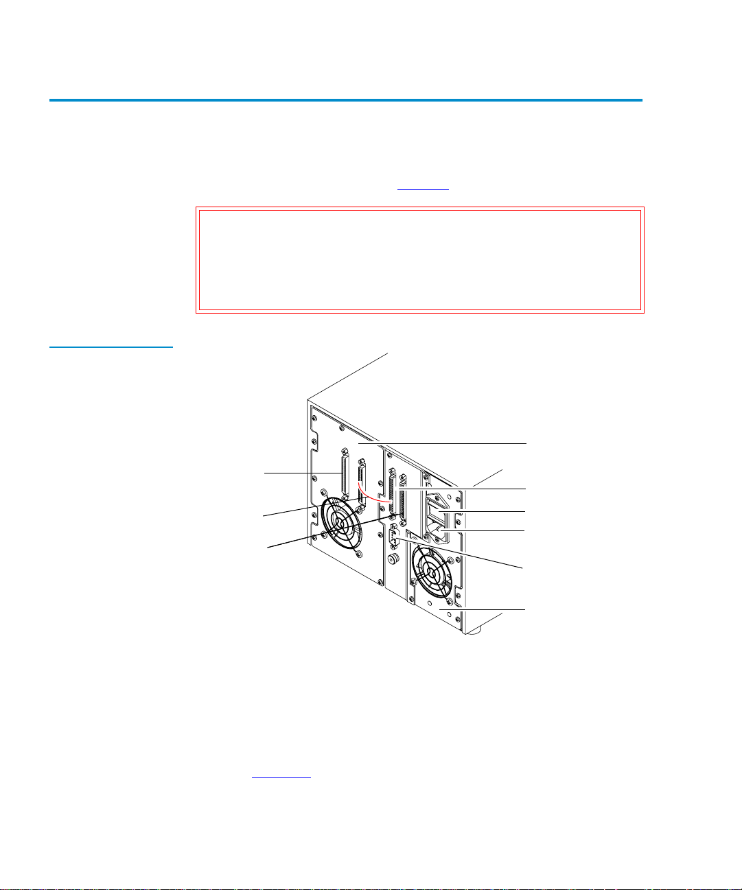
Connecting the Library 2
Complete the following procedure to connect the power cord and
SCSI cables to the library (see figure 9
Caution: Verify that the library controller is connected to the
same type of SCSI bus as the drive on that bus. For
example, connecting a single-ended SCSI library to a
differential SCSI adapter will cause a host system
malfunction.
Figure 9 Rear Panel
Cable Connectors
).
Tape drive assembly
Connect to a
SCSI device
(or install
terminator)
Connect
together
Connect to
host
SCSI connectors
(library controller)
Power switch
Power connector
Serial port
(FSE use only)
Power supply
To connect the library:
1 Verify that the library’s power switch is in the off positi on. It i s
not necessary to power down the host.
2 Connect one end of the short SCSI cable supplied with the to
the library controller’s SCSI connector closest to the tape drive
(see figure 10
).
16 Quantum|ATL PowerStor L200 Series Library User’s Guide
Page 33
Chapter 2 Installing the Library
Connecting the Library
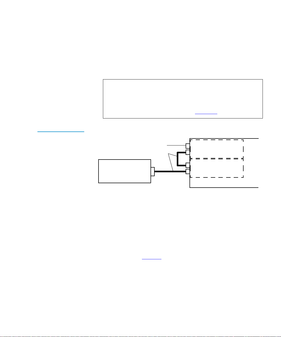
3
Connect the other end of the short SCSI cable to the tape drive
SCSI connector closest to library controller.
4 If the is a stand-alone external SCSI device, install the SCSI
terminator in the connector at the far left (l ooking at the back of
the library). Verify that the SCSI bus is terminated properly.
Note: Depending on the system configuration, the SCSI bus
initiates at the host, connects to the library controller,
then to the tape drive, and then to any other SCSI
devices on the bus. It must be terminated at the last
SCSI device on the bus (see figure 10
).
Figure 10 SCSI
Cabling stand-alone
Connection Scenario
SCSI cable to next SCSI
device (or install the
supplied teminator)
Supplied SCSI cables
Host
Connect one end of the long SCSI cable supplied with the
5
Drive (SCSI ID 1)
Library Controller
(SCSI ID 0)
Library (Top)
library to the SCSI connector closest to the power switch on the
back of the library. Connect the other end of this cable to the
host’s SCSI adapter connector.
6 Secure the cables, using the wire cable clamps or screws
provided.
7 Connect the power cord to the power connector on the back of
the library (see figure 9
8 Connect the other end of the power cord to the site power.
).
Quantum|ATL PowerStor L200 Series Library User’s Guide 17
Page 34

Chapter 2 Installing the Library
Running the Power-on Self-test
Running the Power-on Self-test 2
Run the power-on self-test (POST) to verify proper system
installation.
Turn on the library using the power switch on the back of the
library. The POST runs automatically. The following message is
displayed:
PowerStor POST
Table 1 POST Pass/
Error Messages
Table 1
lists the tests that are run during POST along with the OCP
pass or error messages associated with these tests.
POST Test
(Description)
Pass Error
ROM EDC (flash ROM
EDC)
Micro RAM
(microprocessor local
RAM test)
UART
Other PowerStor POST 4 Other POST Error in
(QUART test)
PowerStor POST 1 EDC POST Error in ROM
PowerStor POST 2 Micro
RAM
PowerStor POST 3 UART POST Error in UART
Messages
EDC
POST Error in
Micro RAM
Other
Next the drive and the library are initialized. If the optional bar
code reader is present (and the bar code enable mode is set), the
cartridge bar code labels are read. The OCP buttons are not active
until the Library Idle message is displayed on the library OCP.
The following messages are displayed:
Library INIT
Library Idle
18 Quantum|ATL PowerStor L200 Series Library User’s Guide
Page 35

Chapter 2 Installing the Library
Configuring the Library
If all the POST tests are completed successfully, and the drive and
library are initialized, the library is ready for operation. If the tests
did not complete, run the POST again; if the tests are still not
complete, the library needs service.
Note: To rerun the POST, turn off the library. Wait ten seconds,
then turn the library power on again.
Configuring the Library 2
Configuration consists of verifying that the lib rary and the internal
drive have the correct SCSI ID settings. The system uses SCSI IDs
to identify or address devices, such as the library controlle r and the
tape drive on the SCSI bus.
If the library is one of multiple SCSI devices on the bus, be sure to
use a SCSI ID that is unique from any other device or system ID on
the SCSI bus (see table 2
).
Table 2 SCSI ID
Default Settings
Verifying the SCSI Settings
SCSI ID Device
1Tape drive
0 Library controller
To view the current SCSI ID settings using the OCP (see figure 1
2
1 Press Select until the message SCSI ID? is displayed.
2 Press Next to enter the SCSI ID menu and display the message
View ID?.
3 Press Enter to view all the SCSI IDs.
Quantum|ATL PowerStor L200 Series Library User’s Guide 19
):
Page 36

Chapter 2 Installing the Library
Configuring the Library
4
If the SCSI IDs listed are correct for the system configuration,
press Select to return to the main menu.
If the SCSI IDs are incorrect for the system configuration,
change the tape drive, or library controller SCSI ID setting (see
Changing the SCSI ID Settings
on page 30).
20 Quantum|ATL PowerStor L200 Series Library User’s Guide
Page 37

Chapter 3
3Operator Control Panel
This chapter describes the overall menu structure of the operator
control panel (OCP). The following functions are described:
• OCP Functions
• Status
• Eject/Unlock
• SCSI ID
• Mode
• Information
• Code Update
• Tests
Caution: Before executing a men u function c ommand from the
OCP, verify that there is no SCSI bus activity to the
library or drives. Executing commands via the OCP
and SCSI bus simultaneously may result in operation
failure and/or drive unavailability.
Quantum|ATL PowerStor L200 Series Library User’s Guide 21
Page 38

Chapter 3 Operator Control Panel
OCP Functions
OCP Functions 3
The OCP is located on the front panel of the library an d controls all
library local functions.
The OCP consists of an LCD, a power LED, and four buttons:
•
Previous—return to a previous option
•
Next—advance through each option
•
Select—return to the main menu options
•
Enter—enter and execute commands in the current option
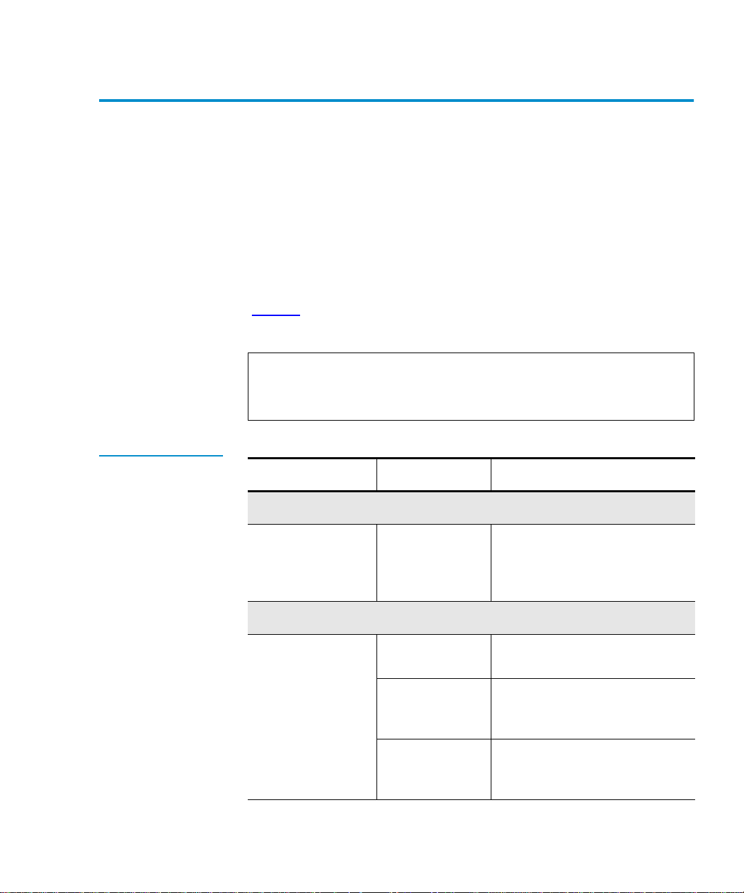
OCP Menus 3
Table 3 OCP LCD
Menu Structure
The LCD displays two lines of characters. Either line can contain a
mixture of messages and/or field codes (see table 3
OCP Menu OCP Submenu Description
Status? Library Init/
At POST
).
Active/Idle
Slot Status 0-7
Drv 0
Displays status of al l slots
Displays tape drive status
DRIVE EMPTY
EJECT/
UNLOCK?
(Pre-v34
firmware)
Eject
Cartridge?
Eject Drive?
Unlock Door
Unloads cartridge from
the drive
Ejects cartridge from the
drive and returns it to its
respective slot (if a drive
has a cartridge in it)
Unlocks the door after the
tape is ejected from the
drive and returned to its
respective magazine slot
22 Quantum|ATL PowerStor L200 Series Library User’s Guide
Page 39

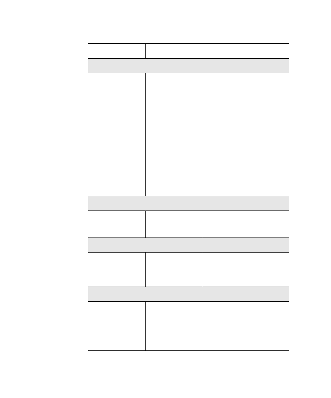
Chapter 3 Operator Control Panel
OCP Menu OCP Submenu Description
OCP Functions
EJECT/
UNLOCK?
(v34+ firmware)
Eject
Cartridge?
Eject Drive?
Unlock Door
LOAD? From Slot #
SCSI ID?
Set SCSI IDs
if selected, then:
Library ?
Drive 0 ?
Press Select to
change
Unloads cartridge from
the drive if cartridge is
present. If cartridge is not
present,
displayed
Ejects the cartridge from
the drive and returns it to
its slot
Unlocks the door after the
cartridge is ejected from
the drive (if
SetUnloadCart
or without unloading the
cartridge from the drive
(if
disabled)
Loads cartridge from
selected slot
Drive is Empty is
Mode/
is enabled),
Mode/SetUnloadCart is
Quantum|ATL PowerStor L200 Series Library User’s Guide 23
Page 40

Chapter 3 Operator Control Panel
OCP Functions
OCP Menu OCP Submenu Description
MODE? Random
Sequential Autoloads cartridge from
Sequential Circ Autoloads cartridge from
Autoload Cart
(Y/N)
EnableBarcode
(Y/N)
AutoClean (Y/N)
SetUnloadCart
(Y/N)
(Requires V34+
firmware)
Load any cartridge from
any magazine slot
low to high magazine slo t
once
low to high magazine slo t
repeatedly
Enable for Seq/SeqCirc
modes
Y (default) to unload tape
drives and return
cartridges to respective
bins when
Door?
given.
N
to leave cartridge in
tape drive when
Door?
Unlock
command is
Unlock
command is given
Information? Loader HW Rev
Loader FW Rev
Loader Mech Rev
Library HW Rev
Library FW Rev
24 Quantum|ATL PowerStor L200 Series Library User’s Guide
Device revision level in
decimal
Firmware rev ision lev el in
decimal
Library revision in
decimal
Device revision level in
decimal
Firmware rev ision lev el in
decimal
Page 41

Chapter 3 Operator Control Panel
OCP Menu OCP Submenu Description
Status
Information?
(continued)
Drive Rev
Loader Life
Cycle
Current Cycles
LDR ERR: ##
Code Update Driv e
Update Drive
Tests Elevator Test
Short Load/
Unload Test
Long Ld/Unload
Test
Drive firmware revision
level in hex
Count from completion of
library 1 POST
From completion of POST
Displays drive and library
microcode levels
Installs microcode from
code update tape into
drive
Status 3
The STATUS? option displays tape drive and magazine slot status.
When the library is turned on, it conducts an automatic power-on
self-test (POST). Upon completion of the POST, the drives and the
library are initialized. The OCP buttons are not active during
initialization. Once the drives are initialized, the main menu
STATUS? options are described as library options. The following
messages are displayed:
• Library Init
• Library Active
• Library Idle
Quantum|ATL PowerStor L200 Series Library User’s Guide 25
Page 42

Chapter 3 Operator Control Panel
Status
If either status message, Library Init or Library Active,
appears on the OCP, the library is in the process of completing an
activity. Wait until Library Idle appears before entering any
commands.
Press Next to get status.
Note: The STATUS? option g ives status information only and
there are no commands to be issued, so the ENTER
button is not functional.
Table 4 Status
Options
Table 4
lists possible Status? options and their respective
messages.
Description Messages Notes
Slot 01234567 Bar Code ___
Displays specific
slot status
Slot Status
Displays status of
all magazine slots
In drive number:
• Empty
• Full
• In transit
Cartridge Status:
Box Filled (cartridge
•
present)
•
0 (cartridge in drive 0)
•
- (empty slot)
•
T (in transit)
If applicable, the
second line of this
message displays a
bar code label entry
The physical
locations are
labeled as Slots 1
through 8.
26 Quantum|ATL PowerStor L200 Series Library User’s Guide
Page 43

Chapter 3 Operator Control Panel
Description Messages Notes
Drive Status
Status
Displays tape
drive status
including tape
drive error
conditions and
cartridge
conditions
Status:
• EMPTY
• InFlux (drive is in the
process of becoming
ready)
• Cl n (cleaning required)
• Code Update (drive is
currently updating its
firmware)
• Calibrating
• Unloading
• Loading
• Cleaning
• Erasing
• Writing
• Reading
• Seeking
• Rewinding
• Idle
Error:
• Hardware Error
• Comm Error
• Library Error
• Drive Empty
(If the last read
Comp
or write operation
was data
compressed, Comp
is displayed in
addition to the
status message)
Cln (If the tape
drive head requires
cleaning,
Cln is
displayed in
addition to the
status message)
When using an unrecorded tape, the tape drive defaults to native
tape density mode.
If you execute a write from the beginning of tape (BOT) when
using an unrecorded tape, the tape drive defaults to native tape
density.
If you execute a write from the BOT when using a recorded tape,
all pre-recorded data (and density changes) are lost. This includes
density changes because they are established when writing from
the BOT.
Quantum|ATL PowerStor L200 Series Library User’s Guide 27
Page 44

Chapter 3 Operator Control Panel
Eject/Unlock
Eject/Unlock 3
The Eject/Unlock? option unlocks the library door and ejects a
cartridge from the tape drive. See Opening the Library Door
page 41 for more information about opening the library door
Caution: Do not press Previous, Next, Select or Enter
until the backup or other tape operations a re stopped
at the host. Pressing these buttons while other
operations are executing may result in operation or
drive failure.
Table 5 lists possible Eject/Unlock? opti ons and their respective
messages.
on
.
Table 5 Eject/Unlock
Options
Description Messages Notes
Eject Cartridge?
•
Unloads the
cartridge from the
tape drive and
reports on drive
status
Unlock Door?
Ejects any
cartridge that is in
the drive, then
unlocks the
library door
Eject Drive?
• Dr v to Slot #
• Library Idle
• Drive Empty
•
Open Door!
• Do or Unlocke d!
The eject function
unloads the
cartridge from the
tape drive
The library door is
unlocked
28 Quantum|ATL PowerStor L200 Series Library User’s Guide
Page 45
Chapter 3 Operator Control Panel
SCSI ID
SCSI ID 3
The SCSI ID? option displays the SCSI IDs for all devices in the
library and allows existing SCSI IDs to be changed.
Make sure all devices on the same SCSI bus have dif ferent SCSI ID
assignments. SCSI ID defaults for the library are:
• Library controller: SCSI ID 0
• Drive: SCSI ID 1
Table 6 SCSI ID
Options
Table 6
lists possible SCSI ID options and their respective
messages.
Note: When changing a SCSI ID, wait at least 30 seconds before
checking the ID. The library may not show the changed
ID until the tape drive ID has been reset.
Description Messages Notes
View ID?
Lists the SCSI IDs
for the library and
drive
Set ID?
Select a device
and change the
SCSI ID setting
Lib 0
Drv 1
Set ID?
Library?
#?
This example shows the
library:
Lib: SCSI ID 0
Drv: SCSI ID 1
The system is set to change the
device ID
Displays and selects the
library and corresponding
SCSI ID to be changed
Drive?
#?
Quantum|ATL PowerStor L200 Series Library User’s Guide 29
Displays an d selects the device
and corresponding SCSI ID to
be changed
Page 46

Chapter 3 Operator Control Panel
SCSI ID
Note: EEROM is maintained through power cycles. SCSI ID
information that is stored in nonvolatile RAM is saved
until you manually change it. SCSI IDs do not
automatically revert to their defaults.
Viewing the SCSI ID Settings
Changing the SCSI ID Settings
To view the current SCSI ID settings:
3
1 Press Select until the message SCSI ID? is displayed.
2 Press Next to enter the SCSI ID menu and display the message
View ID?.
3 Press Enter to view all the SCSI IDs.
4 Press Select to return to the main menu.
To change the SCSI ID for the library controller:
3
1 Press Select until the message SCSI ID? is displayed.
2 Press Next to display the message Set ID?.
3 Press Next to display the message Set ID? Library?.
4 Press Enter to display the SCSI ID selections ( 0-15).
5 Press Previous or Next until the desired SCSI ID is
displayed.
6 Press Enter to select the SCSI ID setting.
7 Press Select to return to the main menu.
To change the SCSI ID settings for the tape drive:
1 Press Select until the message SCSI ID? is displayed.
2 Press Next to display the message Set ID?.
3 Press Next to display the message Set ID? Library?.
4 Press Next to display the message Drive ID?.
5 Press Enter to display the SCSI ID selections ( 0-15).
30 Quantum|ATL PowerStor L200 Series Library User’s Guide
Page 47

Chapter 3 Operator Control Panel
Mode
6
Press Previous or Next until the desired SCSI ID is
displayed.
7 Press Enter to select the SCSI ID setting.
8 Press Select to return to the main menu.
Note: The host (such as a PC) must be rebooted for any library
SCSI ID change to take affect. Turn off the host’s power,
wait ten seconds, then turn the power on again.
Mode 3
The Mode? option controls how the library accesses cartridges.
The Enter button executes the Selected mode and toggles all other
modes to Not Selected. The Enter button also toggles the Yes and
No options (see table 7
).
Table 7 Mode
Options
Warning: The optional bar code reader contains a Class 1 LED.
Do not look at the LED for extended periods of time;
prolonged exposure may be harmful to your eyes.
Description Messages Notes
Random
Automatically
load any cartridge
from any
magazine in the
load cycle
Quantum|ATL PowerStor L200 Series Library User’s Guide 31
•
Selected
• NOT Selected
Page 48
Chapter 3 Operator Control Panel
Mode
Description Messages Notes
Sequential
Load cartridges
sequentially from
the lowest
magazine address
and the lowest
loaded slot
position in that
magazine.
Sequential Circular
Primarily
designed for
testing purposes
Autoload Cart
•
Selected
• NOT Selected
•
Selected
• NOT Selected
The loading and unloadin g
of cartridges sequentially
progresses to the last
cartridge, then the library
stops. To reinitiate this
process, load a cartridge in to
the drive via the OCP or via
a SCSI Command.
Works in conjunction with
AutoloadCart command.
If the library freezes when
this option is selected, power
down the library, wait at
least 10 seconds, then turn
on the power.
Loads cartridges
following an
open/close door
operation
•
• N
Y
Functions only with
Sequential or
Sequential Circ
modes.
Enable Bar Code (optional)
Bar code reader
scans the
cartridge bar code
labels on power-
Y
• N
The bar code labels are read
via the OCP
or a SCSI
status command.
•
up and when the
doors are closed
32 Quantum|ATL PowerStor L200 Series Library User’s Guide
Status display
Read Element
Page 49

Chapter 3 Operator Control Panel
Description Messages Notes
Autoclean (optional)
Mode
Viewing a Mode 3
Toggles whether
or not the library
will automatically
cleans drives
when required
• N
• Y
• CLN Slot
Empty!
• NOT a CLN Tape
• CLN Tape
Expired
• Completes
Successfully
SetAutoUnloadCart (toggle)
Toggles whether
or not the library
•
• N
Y
will unload tape
drives before
unlocking door
To view the current library modes:
See Optional Autoclean
Mode.
Requires v34+ firmware
Y (default) will unload tape
drives at the
Door?
Unlock
command
N will allow tape cartridges
to remain in tape drives at
the
Unlock Door?
command
Setting a Mode 3
1 Press Select until the message Mode? is displayed.
2 Press Enter to display the message Random Selected.
3 Repeatedly press Next to display more modes.
4 Press Select to return to the main menu.
To set the current library modes:
1 Press Select until the message Mode? is displayed.
2 Press Enter to display the message Random Selected.
3 Press Next. Each mode option and status is displayed:
Quantum|ATL PowerStor L200 Series Library User’s Guide 33
Page 50

Chapter 3 Operator Control Panel
Mode
• Sequential NOT Selected
• Sequential Circ NOT Selected
• Autoload Cart: N
• Enable Barcode: N
• AutoClean: N
4 Press Enter to toggle the mode options.
Enter executes the Selected mode and toggles all other modes
to NOT Selected.
For example, if you toggle the Sequential mode to Selec ted, the
Random and Sequential Circ modes are automatically toggled
to NOT Selected
options.
5 Press Select to return to the main menu.
. Enter also toggles each of the Y and N
Optional Autoclean Mode
If the optional autoclean is enabled, the time that a SCSI Move
3
Media command takes to complete increases f rom approxim ately
20 seconds to 60 seconds because the library must wait until
calibration is complete. If cleaning is required, the typical time
increases to a maximum of 10 minutes while the drive is cleaned.
To use:
1 Load the cleaning cartridge into slot 7.
2 Press Enter to enable AutoClean: Y.
When AutoClean is enabled, the status of slot 7 becomes
unviewable. The OCP cannot be used to load a cleaning cartridge.
After the manual cleaning cycle is complete, the second line of the
OCP will display an idle message. Turn off the library. Wait at
least ten seconds. Turn on the library. After the initialization
process is complete, set the AutoClean parameter to N. The
cleaning cartridge may then be ejected.
34 Quantum|ATL PowerStor L200 Series Library User’s Guide
Page 51

Chapter 3 Operator Control Panel
Information
Firmware Updates
Following a library firmware code update, the mode settings will
3
revert to their defaults:
Random Access: Selected
Bar Code Read: N
Sequential Access: Not Selected
Autoload Cart: N
Sequential Circ: Not Selected
AutoClean: N
Set Auto Un load Cart: Y
Information 3
The Information? option displays the device revision number,
software revision number, library cycle count and library error
Table 8 Information
Messages
count (see table 8
Information
Type
Ldr Hw Rev ##
Ldr Rw Rev ##
Ldr Mech Rev ##
Lib Hw Rev ##
Lib Fw Rev ##
Drive Rev ##
).
Message Notes
Device hardware revision level
Device firmware revision level
Library revision level
Library hardware revision level
Library firmware revision level
Drive firmware revision level
†
†
†
†
†
‡
Library Life
Cycle Count
†
decimal format
‡ hex format
Quantum|ATL PowerStor L200 Series Library User’s Guide 35
##
Count starts from completion of first
†
POST
Page 52

Chapter 3 Operator Control Panel
Code Update
Information
Message Notes
Type
Current
Cycles
Ldr Err: ##
†
decimal format
‡ hex format
##
Count starts from completion of most
recent POST
Library error count
†
†
Code Update 3
The Code Update? option displays what tape drive is installed
and installs new microcode for the tape drive through the cartridge
).
Press ENTER to start the
automated code updating
process for the selected drive
Table 9 Code Update
Messages
or the host (see table 9
Option Message Note
Update
Drive #
Update Drive 0
(.) T (test)
V (release)
(h) T (test)
V (release)
Installing New Drive Microcode
36 Quantum|ATL PowerStor L200 Series Library User’s Guide
For detailed microcode update procedures, contact Quantum|ATL
3
Custome r Support or your service representative.
Revision level is in decimal
format
Revision level is in hex format.
Page 53

Chapter 3 Operator Control Panel
Tests
Tests 3
The TESTS? option controls the library internal self-test functions.
To move through the Tests? option:
• If Previous or Next is pressed during a test, the next message
test is displayed along with the message:
A Test is Active
When the original test is completed the next test will start.
• If Enter is pressed during a test in progress, the test will be
terminated. Press Enter to restart a test from the beginning,
once the termination process completes (see table 10
).
Table 10 Tests
Options
Description Messages Notes
Elevator Test
Tests the library
elevator function.
This is a one cycle
test.
Active or
Aborted
The CHM is positioned to each
available data transfer element
(drive) or data storage element
(magazine slot). If the
magazine is not present, the
CHM cannot be positioned to
those slots. This test is
functionally equivalent to
SCSI
Element
Load/Unload Test
Randomly loads
and unloads
cartridges into the
tape drive.
This is a one cycle
test.
Active or
Aborted
Unloads any cartridge in the
drive, inserts a cartridge in the
drive, and replaces the
cartridges in their slots. The
drive is left empty.
Position to
commands.
Quantum|ATL PowerStor L200 Series Library User’s Guide 37
Page 54

Chapter 3 Operator Control Panel
Tests
Description Messages Notes
Long Ld/ Unld Test
Randomly loads
and unloads
cartridges into the
tape drive
repeatedly, until
the test is aborted
by pressing the
Enter button on
the OCP.
Active or
Aborted
Loads and unloads the drive
with cartridges from random
slots.
38 Quantum|ATL PowerStor L200 Series Library User’s Guide
Page 55

Chapter 4
4Using the Library
This chapter describes how to use the library:
• Using the Library Door
• Using Tape Cartridges
• Using the Cartridge Magazine
Using the Library Door 4
The library holds one removable 6-cartridge magazine. Slots are
labeled 1 through 6. The library recognizes these slots as cartridges
0-5 (see figure 11
The remaining two slots (7 and 8) are fixed and internal. The
library recognizes these slots as 6 and 7. They are located behind
the removable magazine, to the left of the tape drive.
Quantum|ATL PowerStor L200 Series Library User’s Guide 39
).
Page 56
Chapter 4 Using the Library
Using the Library Door
Figure 11 Slot
Locations
Internal
drive
Internal
slots 7-8
Magazine
slots 1-6
Caution: To prevent cartridge jams, use the space on the front
of the cartridge for labels. Do not put labels on any
other location.
Caution: Never attempt to move the CHM manually. Damage
to the library may occur if the CHM is blocking
access to the fixed cartridge slot. Recycle power and
wait until Library Idle is displayed on the OCP.
The CHM will then be in its home position.
Note: Use physical slot 1 (OCP slot 0) when performing a drive
microcode update; use physical slot 8 (OCP slot 7) when
using the optional AutoClean mode.
Note: Insert and remove all cartridges from the front of the
magazine.
40 Quantum|ATL PowerStor L200 Series Library User’s Guide
Page 57

Chapter 4 Using the Library
Using the Library Door
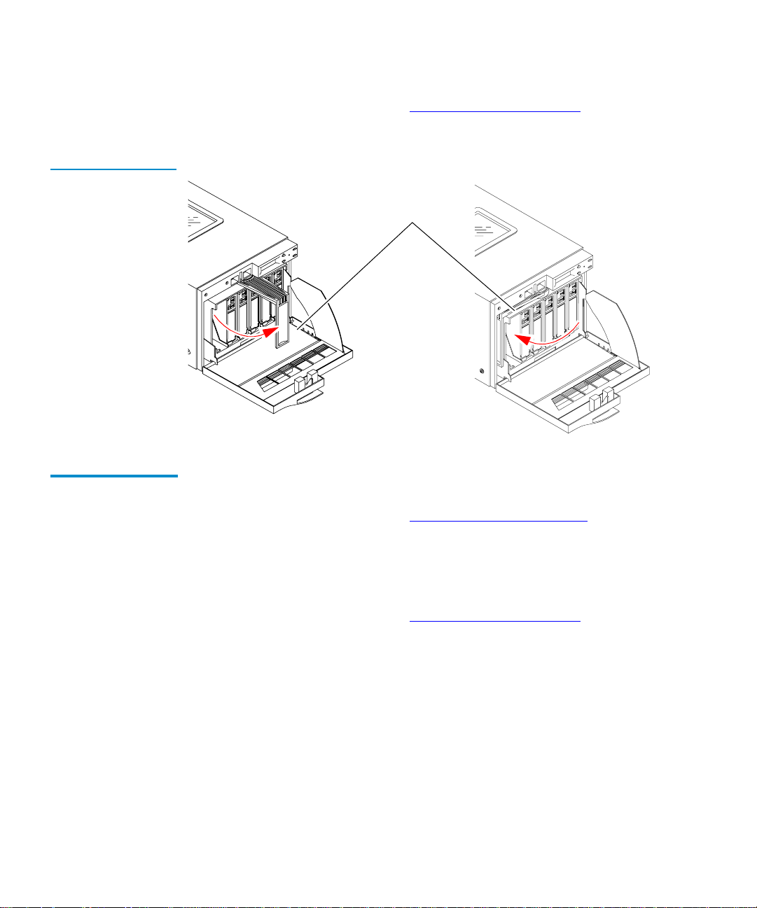
Opening the Library Door
To open the magazine door, using the OCP:
4
1 Press Select until the message EJECT/UNLOCK? is
displayed.
2 Press Next to display the message Eject Cartridge?.
3 Press Next to display the message Unlock Doors?.
4 Press Enter to display the message Are you sure?.
5 Press Enter to remove any cartridge from the drive and
display the message Open Doors!.
This activity can take up to three minutes if the cartridge is to
be removed from the drive and the end of data is at the end of
the tape spool. Press any other button to stop the operation.
6 Open the door using the handle.
Note: When the door is unlocked, the message Door
Unlocked! is always displayed. The only way to
restore library operation is to open and close the
library door.
Closing the Library Door
To close the library door, push the door until it latches.
4
The door automatically locks after approximately five seconds.
The library automatically executes a scan magazine function.
When the scan magazine function is complete, the message
Eject/Unlock? is displayed on the OCP. If the optional bar c ode
reader is present, the cartridge label bar codes are read.
Quantum|ATL PowerStor L200 Series Library User’s Guide 41
Page 58

Chapter 4 Using the Library
Using Tape Cartridges
Using Tape Cartridges 4
This sect ion contains information on:
• Loading and unloading data cartridges
• Using cleaning cartridges
• Bar code labels
Inserting a Cartridge
To insert a tape cartridge into the magazine:
4
1 Open the library door.
2 Verify that all library SCSI library activity has stopped (the
message Library Idle will be displayed on the OCP).
3 Set the write-protect switch on the tape cartridge t o the desired
position (see figure 12
).
Note: The cartridge is write-protected if the orange indicator
is visible. The cartridge is write-enabled if the orange
indicato r is not visible.
4 Orient the tape cartridge with the write-protect switch at the
top (see figure 12
).
42 Quantum|ATL PowerStor L200 Series Library User’s Guide
Page 59
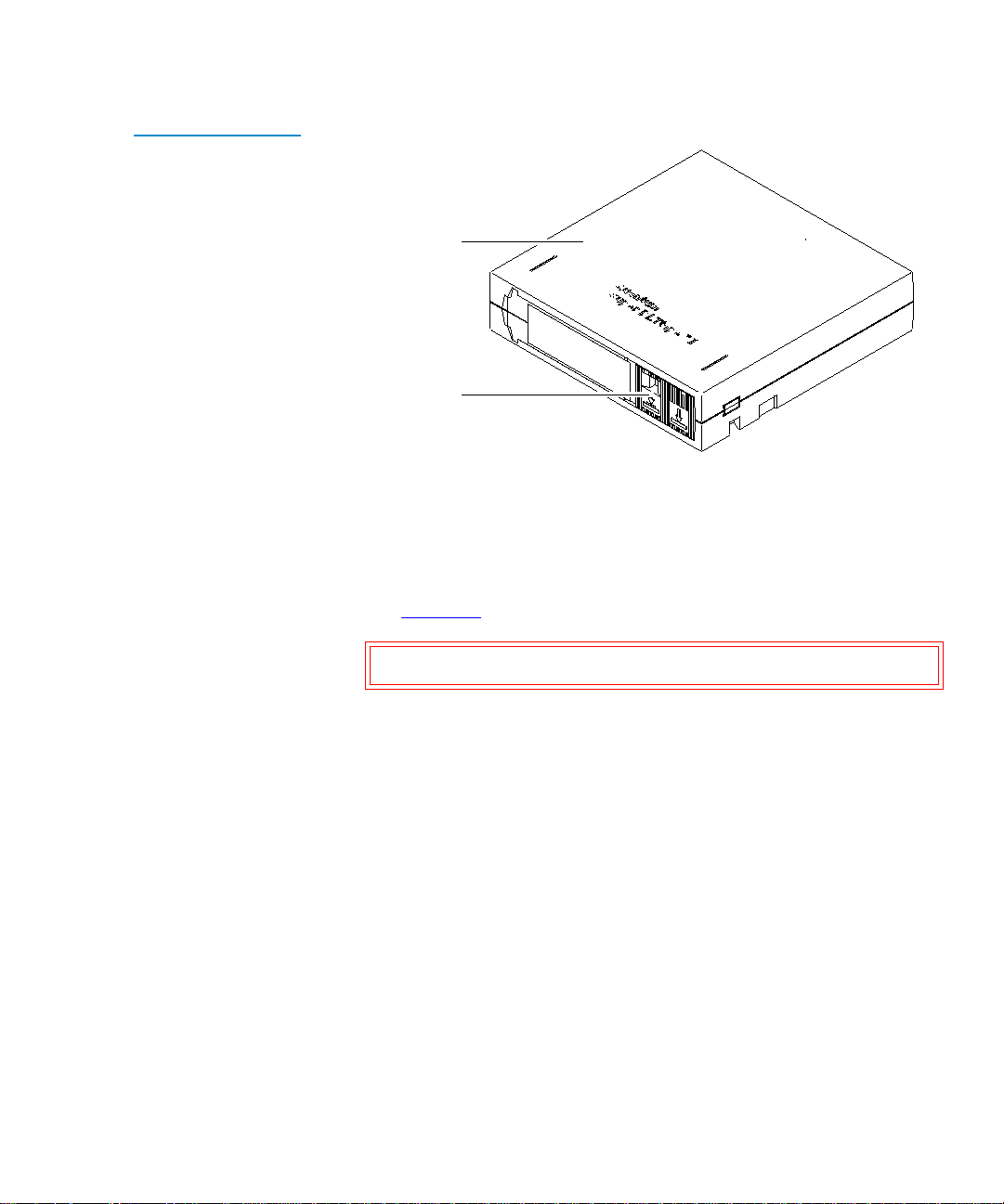
Figure 12 Cartridge
Write-Protect Switch
Chapter 4 Using the Library
Using Tape Cartridges
SDLT tape cartridge
Write protect switch
5
Insert the cartridge into the magazine:
a Push the tape cartridge into the slot until it latches.
b Verify the small metal retaining tab pops out at the opening
of the magazine slot, holding the cartridge in place (see
figure 13
).
Caution: Do not press the metal tab.
Quantum|ATL PowerStor L200 Series Library User’s Guide 43
Page 60
Chapter 4 Using the Library
Using Tape Cartridges
Figure 13 Cartridge
Retaining Tab
Magazine handle
Metal cartridge
retaining tab
Removing a Cartridge
To remove a cartridge from the magazine:
4
1 Press on the tape cartridge until you hear a click.
2 Release the cartridge.
3 The slot has a spring-release action and will partially eject the
cartridge for ease of removal.
Caution: When a tape cartridge is inserted in a magazine
slot, a metal retaining tab pops up from the front
edge of the slot to retain the cartridge. Do not
press on the metal retaining tab. Always use the
press-and-release technique to remove cartridges
from the magazine.
44 Quantum|ATL PowerStor L200 Series Library User’s Guide
Page 61

Chapter 4 Using the Library
Using Tape Cartridges
Loading a Cartridge
To load a cartridge from a magazine slot into the tape drive:
4
1 Press Select until the message Load? is displayed.
2 Press Enter to display the message Load Slot 0?.
3 Press Next until the desired slot number is displayed.
4 Press Enter to select the slot number.
5 Press Enter to display one of the following messages:
• Drive is Full
A cartridge is already installed in the drive. To continue,
unload the cartridge from the full drive (see Unloading a
Cartridge on page 46), then perform the load function
again.
• Slot x is Empty
There is no cartridge available in the selected slot. To
continue, select a slot that contains the cartridge using the
Next or Previous buttons, or insert a cartridge into the
empty slot.
• LOADING or UNLOADING or CALIBRATING COMP
The library is in the process of completing an activity.
When the activity is completed, Lib rary Idle is displaye d on
the OCP.
• IDLE COMP
The load function is complete.
6 Take the action appropriate for the message.
During the loading process, the CHM performs several
functions and displays several messages.
After the tape cartridge is loaded, Library Idle is displayed on
the OCP.
7 Press Select to return to the main menu.
Quantum|ATL PowerStor L200 Series Library User’s Guide 45
Page 62

Chapter 4 Using the Library
Using Tape Cartridges
Unloading a Cartridge
To unload a cartridge from the tape drive:
4
1 Press Select until the message EJECT/UNLOCK? is displayed .
2 Press Next to display the message Eject Cartridge?.
3 Press Enter to display the message Eject Cartridge? Eject
Drive?.
4 Press Enter to display one of the following messages:
• Drive is Empty (there is no cartridge to unload in the drive)
• Drive NOT Present (there is no cartridge to unload in the
drive)
• Eject to Slot 0?
5 Press Enter to unload the cartridge.
The library returns the tape cartridge to its original slot. You
cannot choose to send the cartridge to a different slot.
After the tape cartridge is unloaded, Library Idle is displayed
on the OCP.
6 Press Select to return to the main menu.
Using the Cleaning Cartridge
If the tape drive detects a f ailure during the cal ibration routine or if
4
an unrecoverable hard error occurs while writing or reading a
tape, the message Cln is displayed on the OCP. This message
indicates that the drive head may be contaminated and in need of
cleaning.
Note: Always use the cleaning cartridge to clean the drive. Do
not use cleaning solvents or attempt to service the tape
drive head.
46 Quantum|ATL PowerStor L200 Series Library User’s Guide
Page 63

Chapter 4 Using the Library
Using Tape Cartridges
To use a cleaning cartridge on a non-SDLT type tape drive:
1 Open the library door (see Opening the Library Door on
page 41).
2 Remove the 6-cartridge magazine.
3 Insert the cleaning cartridge into slot 7 (see figure 11).
4 Replace the 6-cartridge magazine.
5 Close the library door (see Closing the Library Door).
6 Load the cleaning cartridge into the drive:
a Press Select until the message LOAD? is displayed.
b Press Enter to display the message From Slot #?.
c Select 7 and press Enter to display the message To Drive.
d Press Enter to automatically begin the cleaning routine.
7 When the cleaning routine is complete, unload the cleaning
cartridge into its original slot (see Unloading a Cartridge
).
Handling and Storing Cleaning Cartridges
The cleaning cartridge can be used 20 times. When the drive
detects that a cleaning cartridge has expired, the drive rewinds and
unloads the cartridge. If the cleaning routine is run on a cleaning
cartridge that has not expired, Cln is cleared from the OCP after
the tape rewinds and unloads. The Cln message is cleared when
the tape drive successfully completes a cartridge calibration
routine after a retry.
To limit use of a cleaning cartridge:
• Avoid touching leaders and media with bare fingers. Oils and
4
grease from the skin are especially damaging and may cause
drive failures that require drive replacement.
• Maintain a clean work area to ensure drive reliability.
• Select a site away from line printers, cardboard boxes, or other
sources of dust and debris.
• Follow handling and storage guidelines.
Quantum|ATL PowerStor L200 Series Library User’s Guide 47
Page 64

Chapter 4 Using the Library
Using Tape Cartridges
Cln Message 4
Table 11 Cln
Message Indications
Inserting Bar Code Labels
The Cln message may have indicate several problems (see
table 11
Condition Possible Problem Recommended Action
Cln message is
displayed on the
OCP
Repeated Cln
messages with
different data
cartridges
Cln message is
displayed with a
particular cartridge
).
The drive head may
be contaminated
May indicate a
drive failure
May indicate a
media problem in
the data cartridge
If it is non-SDLT type
tape drive, clean the
drive head (see Using the
Cleaning Cartridge).
Call your Quantum|ATL
service representative
Replace the data
cartridge
The library is shipped with bar code labels that can be inserted into
4
the front slide slot (see figure 14
):
1 Orient the bar code label so that the numbers are on top, and
the writing faces outward.
2 Slide the label into the slot on the front of the tape cartridge.
Note: Be sure to use a cleaning label if it is a cleaning
cartridge.
48 Quantum|ATL PowerStor L200 Series Library User’s Guide
Page 65

Figure 14 Bar Code
Label Insertion
Chapter 4 Using the Library
Using the Cartridge Magazine
To obtain additional labels, contact your Quantum|ATL sales
representative.
Using the Cartridge Magazine 4
This section contains information on using the cartridge magazine.
Inserting the Magazine
To insert the magazine into the library (see figure 15
4
1 Open the library door (see Opening the Library Door on
page 41).
1 Pivot the magazine handle out.
2 Place the magazine on the library door.
3 Push the magazine into the library until it clicks.
Note: Do not push on the cartridges when inserting the
magazine into the library.
4 Pivot the magazine handle all the way to the left.
Quantum|ATL PowerStor L200 Series Library User’s Guide 49
):
Page 66
Chapter 4 Using the Library
Using the Cartridge Magazine
Figure 15 Cartridge
Magazine
5
Close the library door (see Closing the Library Door on
page 41).
Pivoting handle4
Open4 Closed4
Removing the Magazine
To remove the magazine from the library:
4
1 Open the library door (see Opening the Library Door on
page 41).
2 Pivot the magazine’s handle out from its closed position
3 Pull the magazine out of the library.
4 Close the library door (see Closing the Library Door on
page 41).
50 Quantum|ATL PowerStor L200 Series Library User’s Guide
Page 67

Chapter 5
5SCSI Interface
This chapter details the SCSI protocol features for the library.
These features include:
• General SCSI Bus Operation
• SCSI Message System
General SCSI Bus Operation 5
This section discusses general SCSI bus operation. The SCSI
specification refers to tape libraries as medium changers.
Note: Tape drive commands are not discussed in this
document but can be found in the SCSI Interface chapter
of the specific product manual.
Quantum|ATL PowerStor L200 Series Library User’s Guide 51
Page 68

Chapter 5 SCSI Interface
General SCSI Bus Operation
Data Transfer 5
Initiator/Target Operation
SCSI IDs and LUNs
The library supports asynchronous and synchronous data
transfers. The product has both differential and single-ended SCSI
interfaces. Odd parity is generated during all information transfer
phases where the device writes data to the SCSI bus, and checked
during all information transfer phases where data is read from the
bus.
During operations that take significant amounts of time, such as
Move Media commands, the device di sconnects from the SCSI bus,
allowing other devices to access the bus. This disconnection is
configurable through the Disconnect-Reconnect Mode Parameters
page.
The library does not act as an initiator on th e SCSI bus and wil l not:
5
• Generate unsolicited interrupts to the host
• Initiate its own SCSI commands
• Assert bus reset
The library always appears as logical unit number (LUN) LUN 0.
5
If the LUN specified in the Identify message is invalid, the library
will accept the Command Descriptor Block (CDB). There are three
cases in which this happens:
• If the command is Inquiry, the target will return the inquiry
data with the peripheral qualifier set to 011, indicating that the
target will never support the LUN in question.
• If the command is Request Sense, the target will return sense
data. The sense key will be Illegal Request, with an additional
sense code of Invalid LUN.
• For any other command, the target will terminate the
command with a Check Condition status, and generates the
sense data.
52 Quantum|ATL PowerStor L200 Series Library User’s Guide
Page 69

Chapter 5 SCSI Interface
General SCSI Bus Operation
Unit Attention Condition
Behavior Around Power-On and SCSI Bus Reset
Queued unit attentions are implemented on this device, and are
5
maintained separately for each Initiator. Unit attentions are created
in the following circumstances:
• Power on
• Bus reset
• Bus device reset message
• Asynchronous media change
• Another initiator changed the mode parameters
It is not unusual for a firmware (microcode) update to complete
two queued unit attentions. Due to a limited number of unit
attention buffers, if an initiator does not clear unit attentions
queued for it, at some point the library stops generating new unit
attentions for that initiator-LUN (I-L) combination. Existing ones
are left queued.
All device SCSI lines go to a high-impedance state when the library
is turned off.
5
The library does not generate any spurious signals on the SCSI bus
when it is turned on.
Within 5 seconds of being turned on, and within 250 milliseconds
(typically under 4 ms) after a bus reset, the library responds to
SCSI bus selections and returns appropriate, normal, responses.
Tape motion commands are returned with a Check Condition
status, Sense Key Not Ready, until the media has been made
ready.
The hard bus reset option is implemented.
The library recognizes multiple bus resets in succession and bus
resets of arbitrarily long duration. It recovers within the time limits
specified above, following the last bus reset.
Quantum|ATL PowerStor L200 Series Library User’s Guide 53
Page 70

Chapter 5 SCSI Interface
SCSI Message System
Other SCSI Functionality
Bus Phases 5
Linked commands and untagged queuing are supported.
5
The library conforms to the bus state transition table shown in the
SCSI-2 Standard, Phase Sequences. The in format ion i n the f oll owi ng
sections also applies.
Attention Signal Response
The library responds to an attention (ATN) condition at every
5
phase transition, as long as the initiator sets the ATN bit before the
target deasserts the request (REQ) for the last byte of the previous
phase. Generally, ATN is recognized immediately by the library,
and it changes the bus phase to Message Out.
SCSI Message System 5
This section discusses status phases, messages, and bus parity
errors.
Status Phase 5
The library enters the status phase just once per command, unless
the initiator requests a retry. The only exception is during error
cases when the device goes immediately to BUS FREE, as defined
in the SCSI-2 standard. The library can return a variety of status
bytes (see table 12
54 Quantum|ATL PowerStor L200 Series Library User’s Guide
).
Page 71

Chapter 5 SCSI Interface
SCSI Message System
Table 12 Status
Bytes
Status Byte Description
GOOD (00) This stat us indicates the library successfully
completed the command.
CHECK
CONDITION
(02)
A contingent allegiance condition occu rred. The
REQUEST SENSE command should be sent
following this status to determine the nature o f
the event.
BUSY (08) The target is busy. This status is returned
whenever the device is unable to accept a
command from a n oth erw is e acce pt ab le in iti ato r.
The initiator should reissue the comma nd at a
later time.
INTERMEDIATE
GOOD (10h)
RESERVATION
CONFLICT
(18h
This status is returned instead of GOOD status for
commands issued with the LINK bit set.
Following the return of this status, the libra ry
will proceed to the COMMAND phase for the
transfer of the next linked command.
This status is returned by the library whenever a
SCSI device attempts to access the library when it
has been reserved for another initiator with a
RESERVE UNIT command.
COMMAND
TERMINATED
(22h)
This is the status returned for a command that
was termina t ed by a TERMINATE I/O PROCESS
message. This status also indicates that a
contingent allegiance condition has occurred.
The Test Unit Ready command is used to determine whether
the library would accept, for example, a Move Medium or
Position command without returning a CHECK CONDITION
status.
Quantum|ATL PowerStor L200 Series Library User’s Guide 55
Page 72

Chapter 5 SCSI Interface
SCSI Message System
Bus Free 5
Bus Parity Errors5
There are several situations when the device will go t o BUS FREE
unexpectedly, as defined in the SCSI-2 standard (see sections 4.1.1
and 4.3):
• An internal hardware or firmware fault that makes it unsafe for
the device to continue operation without a full reset (similar to
a power-up reset).
• ATN asserted or bus parity error detected during non-tape
data transfers.
Bus parity errors (single bit errors) are very serious. They imply
the possibility of undetected double-bit errors on the bus. Most
likely these result in undetected data corruption. On properly
configured SCSI buses, parity errors are extremely rare. If any are
detected, they should be addressed quickly by improving the
configuration of the SCSI bus. A well-configured SCSI system in a
normal environment should be virtually free of bus parity errors.
Bus parity errors cause the library to either retry the operation, go
to Status phase, or go to BUS FREE and prepare sense data.
Retrying of parity errors during the data out phase is normally not
done, but can be enabled by changing the EnaParErrRetry
parameter in the Vendor Unique (VU) EEROM mode page. This
feature is disabled by default because of negative impacts on
device performance. Additionally, the data stream on writes
cannot be pipelined.
56 Quantum|ATL PowerStor L200 Series Library User’s Guide
Page 73
Chapter 6
6Troubleshooting
Guidelines
This chapter contains descriptions of operational problems that
may be encountered and guidelines for dealing with them.
Wherever applicable, corrective information has also been
provided to assist in problem resolution.
Several library problems produce error messages that are
displayed on the OCP. See appendix B, Error Messages and
Definitions for more information.
Quantum|ATL PowerStor L200 Series Library User’s Guide 57
Page 74

Chapter 6 Troubleshooting Guidelines
Basic Library Operation
Basic Library Operation 6
When operating the library:
• Check the tape leader in the cartridge by lifting the cartridge
latch that opens the door, exposing the leader. Be sure the
leader is in the correct position (see figure 16
• Verify that the cartridge door is fully closed and the current
slot is correct for the starting cartridge.
Caution: Do not touch the exposed magnetic tape. If the tape
leader is not in the correct position, use a new
cartridge.
Figure 16 Open ing
the Cartridge Door
).
Reel lock
Tape leader
DLT cartridge
58 Quantum|ATL PowerStor L200 Series Library User’s Guide
door
Tape leader
Door lock
(release by
lifting with
thumb)
Page 75

Chapter 6 Troubleshooting Guidelines
Operation Failure
Operation Failure 6
Use the following guidelines if operation failure occurs.
Write-Operation Failure
Error Conditions 6
Power Problems 6
Some manual operations, if not performed correctly, may cause
6
write operations to fail.
For example:
• Loading any write-protected tape cartridges when executing
write operations
• Selecting the incorrect cartridge slot from which to initializ e
operations
If an error does occur, read the OCP display to determine the
problem or call your Quantum|ATL Customer Support
representative.
Depending on the error, the OCP may display an error message.
See appendix B, Error Messages and Definitions
for more
information.
If unable to determine the cause of the problem, call your
Quantum|ATL customer support representative.
If the OCP display is not active or your system does not recognize
the library:
• Verify that the power plug is secure
• Verify with your system manager that the library configuration
is correct
If the library power is disconnected when a cartridge is in transit
between the elevator and magazine, the cartridge is moved into
the magazine slot when power is restored.
Quantum|ATL PowerStor L200 Series Library User’s Guide 59
Page 76

Chapter 6 Troubleshooting Guidelines
Operation Failure
60 Quantum|ATL PowerStor L200 Series Library User’s Guide
Page 77

ASpecifications
This appendix provides specifications on the library:
• Physical Specifications
• Perform ance Specifications
• Power Specifications
• Environmental Specifications
• Operating Vibration Specifications
• Operating Shock Specifications
Appendix A
• Non-Operating Vibration Specifica tions
• Non-Operating Shock Specifications
• Electromagnetic Interference (EMI) Susceptibility
• Acoustic Noise Emissions
• Drive Reliability Factors
Quantum|ATL PowerStor L200 Series Library User’s Guide 61
Page 78

Physical Specificatio ns
Physical Specifications 1
Table 13 Library
Dimensions
Figure 17 Li brary
Dimensions
This section includes library dimensions (see table 13
configuration information (see figure 17
).
) and desktop
Description Rack-Mount Desktop
Height, without feet 6.9 in. (17.5 cm) 7.0 in. (17.8 cm)
Height, with feet, cover n/a 7.6 in. (20.3 cm)
Width 8.6 in. (21.9 cm) 8.9 in. (22.5 cm)
Depth 22.8 in. (57.8 cm) 22.8 in. (57.8 cm)
Weight, with drive
33.3 lbs. (15.1 kg) 37 lbs. (16.8 kg)
(without media)
8.9 inches (22.5 cm)1
22.8 inches (57.8 cm)1
62 Quantum|ATL PowerStor L200 Series Library User’s Guide
7.0 inches1
(17.8 cm)1
Page 79

Performance Specifications
Performance Specifications 1
Performance specifications for the library depend on:
• Data type
• SCSI bus limitations
• System configuration
For drive performance specifications, refer to your specific tape
drive product manual.
Power Specifications 1
This section includes power specifications for the library.
Table 14 Power
Specifications
Description Range
Voltage 100-120 VAC/200-240 VAC
Frequency 50/60 Hz
Amperage 1.0 A/0.55 A
Power Consumption 60 Watts
Quantum|ATL PowerStor L200 Series Library User’s Guide 63
Page 80

Environmental Specifications
Environmental Specifications 1
This section includes environmental specifications for the library.
Table 15 Environmental Specifications
Description Range
Specifications at Power-On
†
Relative humidity 10% to 90% noncondensing
Humidity gradient 10% per hour
Temperature gradient 27°F per hour (15°C per hour)
across the range
Operating Specificati ons
Temperature 50°F to 104°F (10°C to 40°C)
Relative humidity 20% to 80% noncondensing
Humidity gradient 10% per hour
Dry bulb 50°F to 104°F (10°C to 40°C)
Wet bulb 77°F (25°C)
Temperature gradient 19.8 °F pe r hou r (11°C per hour)
across the range
Temperature shock 18°F (10°C) over two minutes
Altitude -500 to 10,000 ft. (-1 50 to 300 0 m)
Non-Operating Specifications
Temperature -40°F to 150.8°F (-40°C to 66°C)
Relative humidity 10% to 90% noncondensing
Humidity gradient 10% per hour
†
Unpacked for 72 hours with no media in library
64 Quantum|ATL PowerStor L200 Series Library User’s Guide
Page 81

Operating Vibration Specifications
Description Range
Dry bulb temperature -40°F to 151°F (-40°C to 66°C)
Wet bulb temp erature 115°F (46°C)
Temperature gradient 36°F per hour with 9° margin
(20°C per hour with 5° margin)
across the range
Temperature shock 27°F with 9° margin (15°C with
5° margin) over two minu t e s
Altitude -500 to 30,000 ft. (-1 50 to 910 0 m)
†
Unpacked for 72 hours with no media in library
Operating Vibration Specifications 1
Table 16 Operating
Vibration
Specifications
This section includes operating vibration spec ifications for the
library.
Vibration Type Sine Sweep
Frequency range 5-500-5 Hz Upward and downward sweep
Acceleration level 0.25 G Between 22.14 and 500 Hz
0.010 in. DA Between 5 and 22.14 Hz
(crossover)
Application X, Y, and Z axis Sweep rate 1 octave per minute
Quantum|ATL PowerStor L200 Series Library User’s Guide 65
Page 82

Operating Shock Specifica tio ns
Operating Shock Specifications 1
This section includes operating s hock specifi cations for the library.
Table 17 Operating
Shock Specifications
Item Specification
Pulse shape Half sine
Peak acceleration 5 G
Duration 10 ms
Application Two pulses +
per axis; X, Y, Z
Non-Operating Vibration Specifications 1
This section provides non-operating sine and sweep vibration
specifications for the library.
Note: Non-operating specifications do not include tape or
magazine components.
Table 18 NonOperating Vibrati on
Specifications
Vibration Type Sine Sweep
Unpackaged Specifications
Frequency range 10-500-10 Hz Upward and
Acceleration level 1 G 10-500-10 Hz
Application X, Y, and Z
axis
66 Quantum|ATL PowerStor L200 Series Library User’s Guide
downward sweep
Sweep rate; 1/2
octave per minute
Page 83

Non-Operating Shock Specifications
Table 19 Random
Vibration
Specifications
Vibration Type Description
Unpackaged Specifications
Frequency range 10-500 H (X, Y, and Z axes)
Acceleration level 2 G rms (X, Y, and Z axes)
PSD envelope 0.008 G
Packaged Specifications
Frequency range 5 to 300 Hz, vertical (Z axis); 5Hz to 200 Hz
horizontal (X and Y axes)
Vibration levels 1.0 G rms (X, Y, and Z axes)
2
/Hz
Non-Operating Shock Specifications 1
This section includes non-operating shock specifications for the
library.
Table 20 NonOperating Shock
Specifications
Description Half Sine
Unpackaged Specifications
Peak acceleration 30 G
Duration 3 milliseconds
Application Two pulses +
Repetitive/Packaged Specifications
Excitation type Synchronous vertical motion (1 inexcursion)
Shock (bounce) cycles 14,200 total
Quantum|ATL PowerStor L200 Series Library User’s Guide 67
per axis (X, Z axes)
Page 84

Electromagnetic Interference (EMI) Susceptibility
Description Half Sine
Application Half cycles each (X, Y axes);
7100 cycles (normal shipping orientation),
3500 cycles (Z axis)
Drop/Packaged Specifications
Test type Drop shock
Drop height 24 inches
Application 16 drops total (3 edges, 1 corner)
Electromagnetic Interference (EMI) Susceptibility 1
This section includes emission standards and limits for the library.
EMI Emissions 1
The library meets the following international EMI standards:
• FCC Part 15B, Class B (US/Canada)
• EN55022, Class B/EN50082-1 (CE Mark)
• VCCI, Class B (Japan)
• AS/NZS 3548, Class B (Australia/New Zealand)
68 Quantum|ATL PowerStor L200 Series Library User’s Guide
Page 85

Electromagnetic Interference (EMI) Susceptibility
Conducted Emissions
Table 21 Conducted
Emission Limits
Radiated Emissions
Table 22 Radiated
Emissions (30 MHz to
1000 MHz)
This subsection includes conducted emission limits.
1
Frequency Range
(0.15 to 30 MHz)
0.15 to 0.050 66 to 56
0.50 to 5 56 46
5 to 30 60 50
†
The limit decreases with the logarithm of the frequency
Limits dB
Quasipeak Average
†
56 to 46
This section lists the limits of radiated interference field strength,
1
in the frequency range from 30 MHz to 1000 MHz at a test distance
of 10 meters, for Class B equipment.
Frequency Range = 30 MHz to
1000 MHz
Quasi-Peak Limit dB (uV/m)
@ 10 meters
Radiated Susceptibility
30 MHz to 230 MHz 30
230 MHz to 1000 MHz 37
Above 1000 MHz Not applicable
The radiated susceptibility limits for high frequency electric fields
1
(26 MHz to 1000 MHz) are:
• 3 V/m (rms) 80% modulated 1 kHz
• No errors, no screen distortion (S/W recoverable errors)
• No hardware failure
Quantum|ATL PowerStor L200 Series Library User’s Guide 69
Page 86
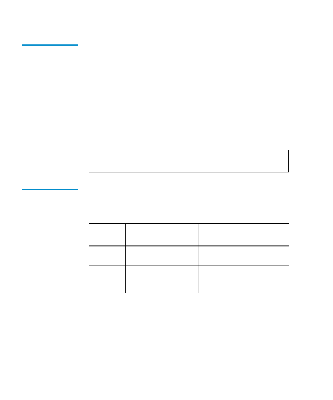
Electromagnetic Interference (EMI) Susceptibility
Conducted Susceptibility
ESD Failure Level Limits
T ab le 23 ESD Failure
Level Limits
The transient voltage is the actual peak voltage above the normal
1
AC voltage from the power source.
The voltage limits for power and data cables are:
• 2 kV S/W recoverable errors
• No hardware failures
The power cable voltage limits are:
• 2.0 kV common mode (no errors allowed)
• 1.0 kV differential mode (S/W rec overable errors, no hardware
failure)
Note: Maximum energy in a single pulse from the transient
generator must be limited to 2.5 W.
This section lists the E SD failure level limits for normal operator
1
access areas.
Failure
Type Equipment
Failure
Level Allowable Errors
Hardware Office to 12 kV No operator intervention (soft
recoverable errors allowed)
Hardware Office to 15 kV No component damage -
operator intervention allowed
(soft and hard errors allowed)
70 Quantum|ATL PowerStor L200 Series Library User’s Guide
Page 87

Acoustic Noise Emission s
Acoustic Noise Emissions 1
This section lists the acoustic noise emission levels in English. The
same information is provided in German (see table 25
).
Table 24 Acoustic
Noise Emissions
(English)
Table 25 Acoustic
Noise Emissions
(German)
Acoustic - Declared values per ISO9296 and ISO 7779/EN27779
Sound Pressure Level
Sound Power Level
LwAd, B
Product Idle
Operating
(Streaming) Idle
LpAm, dBa
(bystander position)
Operating
(Streaming)
Library 5.8 5.8 47.9 48.2
Current values for specific configurations are available from Quantum|ATL
representatives. 1B = 10 dBA
Schallemissionswerte - VorläufigeWerteangaben nach ISO 9296
und ISO 7779/DIN EN27779
Schalldruckpegel
Schalleistungspegel
LwAd, B
Gerfdt Leerauf
Betrieb
(Streaming) Leerauf
LpAm, dBa
(Zuschauerpositionen)
Betrieb
(Streaming)
Library 5,8 5,8 47,9 48,2
Aktuelle Werte für Ausrüstungsstufen sind über die Quantum|ATL Equipment
Vertretungen erh™ltlich. 1 B = 10 dBA
Quantum|ATL PowerStor L200 Series Library User’s Guide 71
Page 88

Drive Reliability Factors
Drive Reliability Factors 1
The mean interval between failures of the lib rary unit (less the t ape
drives) is:
• 185,000 power-on hours (POH) mean time between failures
(MTBF)
or
• 1,000,000 mean load/unload cycles between failures (MCBF),
where a failure is charged against one or the other, but not both
Quantum|ATL does not warrant that predicted mean interval
between failures is representative of any particular library
installed for customer use. Actual figures vary from library to
library.
72 Quantum|ATL PowerStor L200 Series Library User’s Guide
Page 89

BError Messages and
Definitions
This appendix lists error messages, descriptions, and
recommended operator actions for the library.
Appendix B
Error Messages 2
Table 26 OCP Error
Messages
OCP Display Description Recommended Operator Action
Drive Stuck i n Flux
Cartridge Fault
Door Unlocked
This section lists error messages displayed on the OCP.
This indicates that the drive
exceeded the timeout allowed for
that operation. The drive was still in
the flux state when the timeout
occurred.
The initial scan of the magazine slots
and the tape drive indicates that
there are more cartridges in the
system than there are slots to store
them.
Quantum|ATL PowerStor L200 Series Library User’s Guide 73
Cycle the library power and retry
the operation.
If the operation fails again, contact
an authorized field service engineer.
Remove excess cartridges.
Page 90

Appendix B Error Messages and Definitions
OCP Display Description Recommended Operator Action
Prepare slot <n> to
receive cart
Cartridge fault Rem
Extra carts
Cartridge fault
Homeless
Cart fault Homeless
Drv <n> In Flux
Drv <n> HwError
Door Unlocked!
LDR ERR: <x>
DLC ERR: <x>
DRIVE ERROR!
LoadFirstCart
FAILED
There are too many cartridges in the
library.
No slot available for a cartridge in
the drive.
These error messages appear when
the OCP is used to initiate a system
test routine. Each message indicates
a reason why the test can not be
initiated.
The error code was returned by the
loader process.
An error occured communicating
with the tape drive.
Occurs when the Autoload Cart
command is set and there is no
cartridge to load.
Open the door and empty a
magazine slo t by removing a
cartridge.
Correct problem and retry.
Error code descriptions are listed in
Library Error Definitions
on
page 76.
Cleaning FAILED
The attempted cleaning cycle failed. Check for:
• A valid cleaning cartridge is in
the required slot
• The cleaning cartridge has not
expired
CLN slot Empty
CLN Tape Expired
A cleaning cartridge was not found
in the required slot 7.
The cleaning cycle was not
Insert cleaning cartridge in slot 7
and retry the operation.
Replace the cleaning cartridge.
completed because the cleaning
cartridge has expired.
NOT a CLN Tape
74 Quantum|ATL PowerStor L200 Series Library User’s Guide
The cartridge in the cleaning slot is
not a cleaning cartridge.
Insert a cleaning cartridge in the
cleaning slot.
Page 91

Appendix B Error Messages and Definiti on s
OCP Display Description Recommended Operator Action
CUP FAILED! CUP
Timeout
CUP FAILED
Incidental
Ldr/Drv Timeout In
Retry
Loader Timeout
In Retry
Prepos Timeout
In Retry
** Ldr Err<xx>***
Attention Needed
The requested code update
operation failed and the unit timed
out during the code update process.
The requested code update
operation was aborted due to a
failure of a preliminary
operation:drive communication
failure or timeout.
CHM failed to move the cartridge
into the drive.
Drive failed to load the cartridge.
The command aborted after the
maximum number of retries was
exceeded.
The command aborted after
maximum number of retries was
exceeded trying to preposition the
CHM.
An error code xx was returned from
the loader. If the command was
severe, the doors will unlock and
Attention Needed is appended to
the error message.
Retry the operation.
If the operation fails again, contact
an authorized field service engineer.
Cycle the library power and try the
operation again.
If the operation fails again, contact
an authorized field service engineer.
Error code descriptions are listed in
Library Error Definitions
on
page 76.
Elevator Move
Failed
Cart Failed to
Eject
Unable to preposition elevator at
drive during an unload cartridge
operation.
Retry the operation.
If the operation fails again, contact
an authorized field service engineer.
Drive did not eject cartridge when
commanded to do so.
Quantum|ATL PowerStor L200 Series Library User’s Guide 75
Page 92
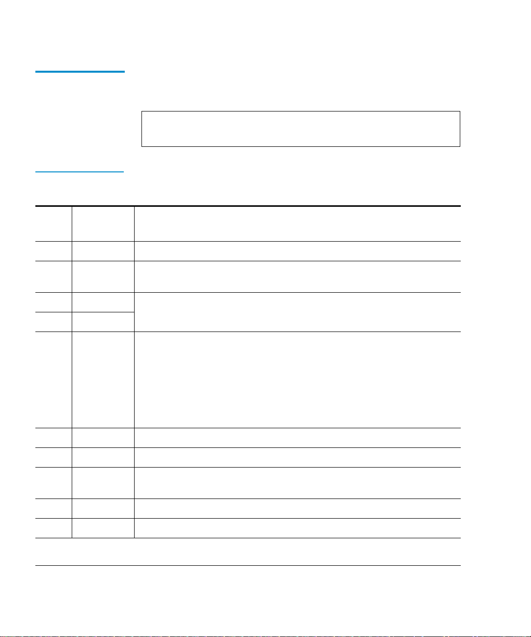
Appendix B Error Messages and Definitions
Error Definitions 2
This section lists the error code, error type, and descriptions for the
library.
Note: If an unrecoverable error occurs, the error message will
Table 27 Library
Error Definitions
Error
Code Error Type Description
80H
81H
82H
83H
84H
Non-error This status indicates no error has occurred.
Fatal Invalid command error: indicates that the loader received an undefined
command or an invalid parameter to a command.
Fatal Undefined error codes
Fatal
Not Fatal A cartridge is in transit after a reset or power up. This error will occur
whenever a power-cycle or reset occurs during a move. The loader
controller will insure that the cartridge is fully loaded onto the CHM and
then will proceed with power-on self-tests.
remain on the OCP until another button is pushed.
The library controller will be responsible for moving the ca rtrid ge either
to its home location, if known, or to the drive before issuing the
Extended Scan Magazine command.
85H
86H
87H
88H
89H
† Retry: the command should be reissued or retried
‡ See description for more details on the cause for this error, and how to recover from the error
76 Quantum|ATL PowerStor L200 Series Library User’s Guide
Fatal Did not find pusher home position during mechanical initialization.
Fatal Did not find PUSHPOS 1 during mechanical initialization.
Fatal Time-out while moving a cartridge onto or off of the CHM during
mechanical initiali zation.
Fatal Time-out finding CHM home position during mechanical initialization.
Fatal Time-out while trying to find PUSHPOS 2 during mechanical initialization.
Page 93

Error
Code Error Type Description
Appendix B Error Messages and Definiti on s
8AH
8BH
8CH
8DH
8EH
8FH
90H
91H
92H
93H
94H
95H
96H
Fatal Did not leave DRIVPOS during mechanical initialization.
Fatal No drive handle installed, or time-out while closing the drives handle
during mechanical initiali zation.
Fatal Time-out during pusher test (did not leave home position).
Fatal Time-out during pusher test finding pusher home posi tion.
Fatal Time-out during pusher test or during CHM home position lea v ing
pusher home position while moving, towards
PUSHPOS2.
Fatal Undefined error code
Fatal No cartridge was present in the drive during a cartridge unload.
†
Retry
Time-out while attempting to find PUSHPOS 1. Positi on i n fron t of the dri ve
before unloading a cartridge from drive onto the CHM.
†
Retry
Time-out opening drive handle during cartridge un loads. The library
controller determines if the drive is still in unloa d ed state after receiving
this error code. If the drive is still in the unloaded state, reissue the
command. If the drive is not still in the unloaded state, then another
unload command must be issued to the dr ive prior to retrying this
command.
†
Retry
Time-out attempting to find the pusher home position durin g a cartridge
unload.
†
Retry
Time-out while moving a cartridge from the drive onto the CHM. If this
error occurs, the loader controller will try to move the cartridge back into
the drive. The receipt of this error code implies the cartridge has been put
back into the drive.
†
Retry
Retry
†
Time-out while moving the CHM from the drive load position to the slot
position during a cartridge unloads. Reissue
by
Unload.
Scan Magazine, followed
Time-out finding PUSHPOS 1 during a cartridge unload.
† Retry: the command should be reissued or retried
‡ See description for more details on the cause for this error, and how to recover from the error
Quantum|ATL PowerStor L200 Series Library User’s Guide 77
Page 94

Appendix B Error Messages and Definitions
Error
Code Error Type Description
97H
98H
99H
9AH
9BH
9CH
9DH
9EH
9FH
See
description
See
description
†
Retry
†
Retry
†
Retry
†
Retry
†
Retry
†
Retry
†
Retry
Time-out occured during Unload command, while un loading a cartri dge
‡
into a slot during a cartridge unload. Reissue command.
This error can also occur during an
Extended Scan Magazine
command, which means a cartridge (that was in the magazine) is now on
the CHM. Reissue
Scan Magazine, followed by Unload.
Time-out while attempting to find the pusher home position durin g a
‡
cartridge unload. (This error actually occurred after the cartridge was
successfully placed back into the magazine so the move is effectively
completed.) Reissue
Scan Magazine.
Time-out while moving the CHM to DRIVPOS during a cartridge unload.
Reissue
Scan Magazine, followed by Unload.
Time-out finding PUSHPOS 2 during a cartridge unload.
Could not unlock the door during an Unlock Door.
Did not find all valid slot positions during a Scan Magazine.
Time-out did not leave cartridge type window during a Scan
Magazine
.
Time-out leaving DRIVPOS during a Scan Magazine.
Could not lock the door during a Door Lock command, or during a
Scan command if door is unlocked.
A0H
A1H
A2H
A3H
A4H
† Retry: the command should be reissued or retried
‡ See description for more details on the cause for this error, and how to recover from the error
78 Quantum|ATL PowerStor L200 Series Library User’s Guide
Fatal Cartridge already in drive during a Load Cartridge.
Fatal No cartridge in the selected slot during a Load Cartridge.
See
description
†
Retry
†
Retry
Time-out while moving CHM to slot position during a Load
‡
Cartridge
Cartridge
. Reissue Scan Magazine, followed by Load
.
Time-out attempting to find the PUSHPOS 1 during a Load Cartridge.
Time-out moving cartridge from the slot onto the CHM during a Load
Cartridge
.
Page 95

Error
Code Error Type Description
Appendix B Error Messages and Definiti on s
A5H
A6H
A7H
A8H
A9H
AAH
ABH
ACH
†
Retry
See
description
†
Retry
See
description
Time-out finding pusher home position during a Load Cartridge.
Time-out moving CHM to drive-load position during a Load
‡
Cartridge
Cartridge
. Reissue Scan Magazine, followed by Load
.
Time-out while opening the drives handle during a Load Cartridge.
Time-out moving cartridge from the CHM into the drive during a Load
‡
Cartridge
.
If this occurs as the only error, then retry the command. The drive
controller must unload the cartridge from the drive before it can retry.
If this error occurs as the second error after either a
94H or an A9H error, it
is considered fatal.
†
Retry
Time-out while attempting to find PUSHPOS 2 to push cartridge
completely into the drive during a
Load Cartridge.
Non-error This code is not an error and will never be returned in the status error
bytes. It is utilized in the error trace buffer as an indicator every time a
thousand cycles has occurred.
See
description
Time-out finding PUSHPOS 1 (rack wa iting position in front of the drive).
‡
The library controller must unload the cartridge from the drive before it
can retry.
†
Retry
Time-out closing drive handle. This error can occur during a Load
Cartridge
, or after error 94 if the loader controller tries to move the
cartridge back into the drive.
ADH
AEH
Fatal Time-out leaving drive lo ad position to move to drive park position.
Fatal Time-out while moving a cartridge back into a slot after error A4. This
error only happens if the loader controller tries to move a cartridge from
the slot onto the CHM and fails. The loader controller would then try to
move the cartridge back into the slot. If that fails, this error is generated.
AFH
B0H
† Retry: the command should be reissued or retried
‡ See description for more details on the cause for this error, and how to recover from the error
Fatal Undefined error codes
Fatal
Quantum|ATL PowerStor L200 Series Library User’s Guide 79
Page 96

Appendix B Error Messages and Definitions
Error
Code Error Type Description
B1H
B2H
B3H
B4H
B5H
B6H
B7H
B8H
B9H
Fatal Stand-alone mode
Non-error Door open without getting a command. After power-up, this command
can occur as the loader remembers the state of the door.
This is an informational error message and does not require recovery.
Non-error Unit was reset or powered up. This is an informational error message and
does not require recovery.
See
description
See
description
Time-out while prepositioning the CHM during a prepositioning
‡
command. Reissue
Scan Magazine, followed by Preposition.
Did not find all expected slots during an CHM movement. This error can
‡
occur during a load or unload of a cartridge or a
command. Reissue
Scan Magazine, followed by the original
Preposition
command.
†
Retry
Time-out while opening the drive handle, after operate handle command
was received.
Fatal UART test failure
†
Retry
Time-out while closing the drive handle after operate handle command
was received.
Fatal Undefined error codes
BAH
BBH
BCH
BDH
BEH
BFH
† Retry: the command should be reissued or retried
‡ See description for more details on the cause for this error, and how to recover from the error
80 Quantum|ATL PowerStor L200 Series Library User’s Guide
Fatal
Fatal RAM error
Fatal ROM error
Fatal CTC error
Fatal Undefined error codes
Fatal
Page 97

Appendix C
CRegulatory Statements
FCC Statement 3
This equipment has been tested and found to comply with the
limits for a Class A digital device, pursuant to Part 15 of the FCC
Rules. These limits are designed to provide reasonable protection
against harmful interference when the equipment is operated in a
commercial environment. This equipment generates, uses, and
can radiate radio frequency energy and, if not installed and used in
accordance with the instruction manual, may cause harmful
interference to radio communications.
Any changes or modifications made to this equipment may void
the user’s authority to operate this equipment.
Operation of this equipment in a residential area may cause
interference in which case the user at his own expense will be
required to take whatever measures may be required to correct the
interference.
Quantum|ATL PowerStor L200 Series Library User’s Guide 81
Page 98

Industry Canada (Digital Apparatus)
This device complies with Part 15 of the FCC Rules. Operation is
subject to the following conditions:
1 This device may not cause harmful interference, and
2 This device must accept any interference receiv ed, including
interference that may cause undesired operation.
Industry Canada (Digital Apparatus) 3
Referemce: Interference-Causing Equipment Standar d, ICES-003
Issue 2
This Class A digital apparatus meets all requirements of the
Canadian Interference-Causing Equipment Regulations.
Cet appareil numérique de la class e A respecte toutes l es exigences
du Reglément sur le matériel brouilleur du Canada.
CISPR-22
WARNING!
This is a Class A product. In a domestic environment this product
3
may cause radio interference in which case the user may be
required to take adequate measures.
ACHTUNG! 3
Dieses ist ein Gerät der Funkstörgrenzwertklasse A. In
Wohnbereichen können bei Betrieb dieses Gerätes
Rundfunkstörungen auftreten, in welchen Fällen der Benutzer für
entsprechende Gegenmassnahmen verantwortlich ist.
ATTENTION! 3
Ceci est un produit de classe A. Dans un environment
domestique, ce produit peut causer des interférences
radioélectriques. Il appartient alors à l'utilisateur de prendre les
mesures appropriées.
82 Quantum|ATL PowerStor L200 Series Library User’s Guide
Page 99

Notice for USA and Canada Only
Notice for USA and Canada Only 3
If shipped to USA, use the UL LISTED power cord specified below
for 100-120 V operation. If shipped to Canada, use the CSA
CERTIFIED power cord specified below for 100-120V operation.
Plug Cap Parallel blade with ground pin (NEMA 5-15P
configuration)
Cord Type: SJT, three 16 AWG (1.5 mm
18 AWG (1.0 mm
Length Maximum 15 feet (4.5m)
Rating Minimum 10 A, 125 V
ATTENTION
2
) wires
2
) or
LIRE LA REMARQUE DANS LE MODE D’EMPLOI.
REMARQUE 3
CETTE REMARQUE NE CONCERNE QUE LES ÉTATS-UNIS ET
LE CANADA.
En cas d'envoi aux États-Unis, utiliser le cordon d'alimentation
CERTIFIÉ UL et convenant pour 100-120 V.
En cas d'envoi au Canada, utiliser le cordon d'alimentation
CERTIFIÉ CSA et convenant pour 100-120 V.
Fiche Broches parallèles avec une broche de mise à la terre
(configuration NEMA 5-15P)
3
Cordon Type: SJT, trifilaire 16 AWG (1.5 mm
18 AWG (1.0 mm
Longeur Maximum 15 pieds (4. 5m)
Capacité Minimum 10 A, 125 V
Quantum|ATL PowerStor L200 Series Library User’s Guide 83
2
)
2
) ou
Page 100

Laser Statement
Laser Statement 3
Class 1 Laser
Product
Laser Klasse 1 3
Appareil à Laser
de Classe 1
CAUTION: With all panels and enclosures in place, this product is
3
rated as a Class I laser product. The bar code scanner inside this
product, however, is a Class II laser. Avoid exposure to the laser
light emitted from the bar code scanner. Do not stare into the
beam.
CAUTION: Use of controls or adjustments or performance of
procedures other than those specified herein may result in
hazardous exposure.
VORSICHT: Dieses Produkt Enthält Einen Laser der Kategorie II.
Laserstrahlen - Der Strichcode-scanner Gibt Laserstrahlen aus.
VERMEIDEN SIE jeden Blickkontakt und direkten körperlichen
Kontakt mit diesen Strahlen.
VORSICHT: Ein nicht ordnungsgemäßer (siehe hier enthaltene
Anweisungen) Einsatz bzw. Änderungen der Betriebsleistung
können einen Gesundheit gefährdenden Kontakt zur Folge haben.
ATTENTION: Ce produit émet de la classe laser II. Rayonnement
3
laser - NE PAS fixer des yeux le rayon. Éviter les expositions - Le
rayonnement laser est émis à partir du lecteur optique de code
barre.
ATTENTION: L’utilisation de contrôles ou d’ajustements de
performance des procédures autres que ceux indiqués ici peut
entraîner une exposition dangereuse.
Producto Láser de
Clase 1
¡ATENCIÓN! Este producto contiene laser de clase II. Luz de la ser
3
- NO mire el rayo. Evite el contacto con la luz: la luz de laser se
emite desde el explorador de código de barras.
84 Quantum|ATL PowerStor L200 Series Library User’s Guide
 Loading...